

Page 1
301-4480 Revision AA
Alifax Roller 20 Service
Manual
All manuals and user guides at all-guides.com
all-guides.com
Page 2
Rev: Ed. 2 - Rev. 10
Issue: 24.April .2014
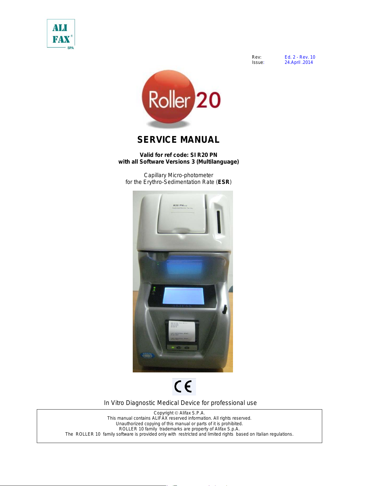
SERVICE MANUAL
Valid for ref code: SI R20 PN
with all Software Versions 3 (Multilanguage)
Capillary Micro-photometer
for the Erythro-Sedimentation Rate (ESR)
In Vitro Diagnostic Medical Device for professional use
Copyright Alifax S.P.A.
This manual contains ALIFAX reserved information. All rights reserved.
Unauthorized copying of this manual or parts of it is prohibited.
ROLLER 10 family trademarks are property of Alifax S.p.A.
The ROLLER 10 family software is provided only with restricted and limited rights based on Italian regulations.
All manuals and user guides at all-guides.com
Page 3
INDEX
ROLLER PRESENTATION ...................................................................................................................................................... 1
ROLLER PN INTERNAL VIEW ................................................................................................................................................ 1
ROLLER REAR SIDE VIEW .................................................................................................................................................... 3
INSTRUMENT PLASTIC COVER REMOVING ........................................................................................................................ 4
1.0 – ROLLER PN TECHNICAL SPECIFICATIONS ESR_PTDS_SI205_ROLLERPN_2-4_EN 2014-Janwary-31 ......... 5
2.0 - WARNINGS ...................................................................................................................................................................... 9
2.1 INDEX OF SYMBOLS ....................................................................................................................................................... 11
3.0 - UNPACKING AND INSTALLATION ............................................................................................................................... 12
4.0 – PRELIMINARY CHECKS, FIRST INSTALLATION AND SOFTWARE UPGRADE ....................................................... 13
5.0 – WASTE TANK REPLACE / EMPTY .............................................................................................................................. 13
6.0 – WASHING TANK LEVEL CONTROL............................................................................................................................. 13
7.0 – INCREASE AVAILABILITY TEST USING THE SMART CARD ..................................................................................... 14
7.1 – SMART CARD ERRORS ................................................................................................................................................................................ 16
7.2 – MULTIPARAMETRIC CARDS ....................................................................................................................................................................... 16
7.2 – PAPER ROLL LOADING - REPLACEMENT .............................................................................................................................................. 17
8.0 – SWITCH ON .................................................................................................................................................................. 18
9.0 – MENU DESCRIPTION ................................................................................................................................................... 18
9.1 – MAIN MENU .................................................................................................................................................................. 19
9.1.1 – MEASURE MENU ....................................................................................................................................................... 19
9.1.1.1 – PATIENT IDENTIFICATION BY External Bar Coded Reader .................................................................................. 20
9.1.1.2 – MANUAL INSERTION OF THE PATIENT ID ........................................................................................................... 21
9.1.1.3 – AUTOGENERATED ID ............................................................................................................................................ 22
9.1.1.4 – RESTORE LAST SESSION ..................................................................................................................................... 23
9.1.1.5 – EXTERNAL SAMPLING PROCEDURE, USING INTERNAL MIXING ..................................................................... 24
9.1.1.6 – EXTERNAL SAMPLING WITHOUT INTERNAL MIXING ........................................................................................ 26
9.1.1.7 – ANALYSIS RESULTS (Display and Printouts) ......................................................................................................... 28
9.1.1.8 – ANALYSIS RESULTS DURING SECOND TAKE OF SAMPLE AND SAMPLE MISSING ....................................... 29
9.1.2 – WASH MENU.............................................................................................................................................................. 30
9.1.2.1 – INTERNAL WASH ................................................................................................................................................... 30
9.1.2.2 – AUTOMATIC WASH ................................................................................................................................................ 31
9.1.2.3 – EXTERNAL WASH .................................................................................................................................................. 32
9.1.2.4 –WASHINGS PROCEDURE DESCRIPTION ............................................................................................................. 33
WASHING USING 2 TEST TUBES ........................................................................................................................................................................ 33
WASHING USING 3 TEST-TUBES (optionally third tube filled with a detergent liquid) ............................................................................... 34
WASHING PROCEDURE FOR MAINTENANCE ................................................................................................................................................ 34
9.1.2.5 WASHING PROCEDURE IN CASE OF USE OF LATEX CONTROLS ........................................................................................... 35
9.1.2.6 – END OF WORKING DAY WASHING PROCEDURE ( Wash and Sleep) ................................................................. 36
9.1.2.7 – WASHING ERRORS ............................................................................................................................................... 37
9.1.2.8 –WASHINGS PROCEDURE ERRORS (MEANING OF WASHING FLAGS IN DEBUG ON) .................................... 37
9.1.3 – STANDARD (Latex control / calibration) ..................................................................................................................... 40
9.1.3.a – BoosterY adjustment when comparing against Westergreen Method ..................................................................... 45
9.1.4 – MIXER ........................................................................................................................................................................ 47
All manuals and user guides at all-guides.com
Page 4
9.1.5 – EMPTY ROLLER ........................................................................................................................................................ 47
9.1.6 – INTERNAL QUALITY CONTROL ............................................................................................................................... 48
9.1.6.1 – WASHING QUALITY CONTROL PRINTOUT - Graph meaning .............................................................................. 49
9.1.6.2 – “NORMAL” ESR AVERAGE CONTROL PRINTOUT - Graph meaning ................................................................... 50
9.1.6.3 – “GLOBAL” ESR AVERAGE CONTROL PRINTOUT - Graph m eani ng .................................................................... 52
9.1.6.3.b – INTERPRETATION OF THE STATI STICAL MEANING ....................................................................................... 54
9.1.6.4 – “NORMAL” CUMULATIVE ESR DISTRIBUTION PRINTOUT - Graph meaning ..................................................... 56
9.1.6.5 – “GLOBAL” CUMULATIVE ESR DISTRIBUTION PRINTOUT - Graph m eaning ...................................................... 57
9.1.6.6 – “NORMAL” DAILY ESR DISTRIBUTION PRINTOUT - Graph meaning .................................................................. 58
9.1.6.7 – “GLOBAL” DAILY ESR DISTRIBUTION PRINTOUT - Graph meaning ................................................................... 59
9.1.6.8 –INSTRUMENT VERIFICATI ON USING THE LATEX CONTROL KIT ...................................................................... 60
9.1.6.9 – ERASE STATISTICAL DATABASE ......................................................................................................................... 63
9.2 – SETUP MENU ............................................................................................................................................................... 65
9.2.1 – CPS MENU ................................................................................................................................................................. 65
9.2.1.1 – CPS’ PARAMETERS ............................................................................................................................................... 65
9.2.1.1.a – MODIFY TYPE OF REFERENCE (CHOOSE BOOSTERY TYPE) (Technical password required) ..................... 66
9.2.1.1.b – MODIFY BOOSTERY’s VALUE (Technical password required) .......................................................................... 67
9.2.1.1.c – MODIFY WHOLE PARAMETRES’ VALUES ....................................................................................................... 68
9.2.1.1.d – MODIFY MODEL FACT’s VALUES (Technical password required) .................................................................... 68
9.2.1.1.e – MODIFY Offset Sensors VALUES (Technical password required) ...................................................................... 68
9.2.1.1.f – MODIFY THERMOSTAT reference value ( Technical password required) ............................................................ 69
9.2.1.2 – CPS Correctors Parameters (Available only if a Multiparametric card is used) (Technical password required) ....... 69
9.2.1.3 – CPS Read ADC ....................................................................................................................................................... 70
9.2.1.4 – FIRST UP ................................................................................................................................................................ 70
9.2.2 – MIX MENU .................................................................................................................................................................. 70
9.2.3 – DATE TIME MENU .................................................................................................................................................... 71
9.2.3.1 – MODIFY DATE TIME VALUE (User level password required) ................................................................................ 71
9.2.4 – FL (Flag List) MENU ................................................................................................................................................... 73
9.2.5 – SETTINGS MENU ...................................................................................................................................................... 75
9.2.5.1 – SOFTWARE VERSION ........................................................................................................................................... 75
9.2.5.2 – PRINT EXPANDED ................................................................................................................................................. 75
9.2.5.3 – PRINT IN RUN ......................................................................................................................................................... 76
9.2.5.4 – LANGUAGE SETUP ................................................................................................................................................ 76
9.2.6 – SETTINGS MENU with “USER LEVEL” PASSWORD LEVEL ACCESS .................................................................... 76
9.2.6.1 – WASH TIME ............................................................................................................................................................ 77
9.2.7 – SETTINGS MENU with “TECHNICAL LEVEL” PASSWORD LEVEL ACCESS .......................................................... 77
9.2.7.1 – INSTRUMENT SERIAL NUMBER ........................................................................................................................... 78
9.2.7.2 – DEBUG .................................................................................................................................................................... 79
9.2.7.3 – CONFIGURATION OF KIND OF ROLLER ( Available from software version 1.00N) ............................................... 79
9.2.7.4 – MAINTENANCE LEVEL RESET .............................................................................................................................. 80
9.2.7.5 – MAINTENANCE LEVEL THRESHOLD SETUP ....................................................................................................... 80
9.2.7.6 – INSTRUMENT GENERAL RESET .......................................................................................................................... 81
All manuals and user guides at all-guides.com
Page 5
9.2.7.7 – PRINT PARAMETERS ............................................................................................................................................ 81
9.2.7.8 – 2 CPS ...................................................................................................................................................................... 82
9.2.7.9 – LATEX PRIMING ..................................................................................................................................................... 82
9.2.7.10 – SYRINGE FAST ..................................................................................................................................................... 82
9.2.7.11 – PEDIATRIC SAMPLES .......................................................................................................................................... 83
9.2.7.12 – ERROR LOG ......................................................................................................................................................... 83
9.2.8 – LOG IN-OUT ............................................................................................................................................................... 84
9.3 – AVAILABILITY MENU .................................................................................................................................................... 85
9.3.1 – WARNING LEVEL (User level password required) ..................................................................................................... 85
9.3.2 – DISPLAY AVAILABILITY ............................................................................................................................................ 86
9.4 – COMM MENU (Technical password required) ............................................................................................................... 87
9.4.1 – SETUP MENU ............................................................................................................................................................ 88
9.4.1.1 – INSTRUMENT NUMBER ......................................................................................................................................... 88
9.4.1.2 – TIMEOUT ................................................................................................................................................................. 89
9.4.1.3 – ATTEMPTS .............................................................................................................................................................. 89
9.4.1.4 – MISSING ID ............................................................................................................................................................. 90
9.4.1.5 – DO ON TIMEOUT UART ......................................................................................................................................... 90
9.4.1.6 – ACK ......................................................................................................................................................................... 90
9.4.1.7 – BAYER (only with BCI interface) .............................................................................................................................. 91
9.4.1.8 – 6 Parameters Transmission (under developm ent). .................................................................................................. 91
9.4.1.9 – Curve Parameters Transmission (under dev el opm ent). ........................................................................................... 91
9.4.1.10 – PROTOCOL INTERFACE OPTIONS .................................................................................................................... 92
9.4.1.10.a – DAT 8 INTERFACE (NO QUERY) ...................................................................................................................... 93
9.4.1.10.b – DAT 15 INTERFACE (NO QUERY) .................................................................................................................... 94
9.4.1.10.c – BCI INTERFACE (QUERY) ................................................................................................................................. 95
9.4.1.10.d – No HOST ............................................................................................................................................................ 95
9.4.1.11 – PROTOCOL INTERFACE EXPLICATION ............................................................................................................. 95
9.4.1.12 – LATEX PROTOCOL INTERFACE EXPLICATION................................................................................................. 97
9.4.1 – TEST MENU ............................................................................................................................................................... 98
9.5 – TECH MENU (Technical password required) ............................................................................................................... 100
9.5.1 – PUMP CONFIGURATION ........................................................................................................................................ 101
• Internal taking: ....................................................................................................................................................................................................... 101
• External taking: ..................................................................................................................................................................................................... 101
• Fast: ........................................................................................................................................................................................................................ 102
• Retention: ............................................................................................................................................................................................................... 102
• Reset persistaltic: ................................................................................................................................................................................................. 102
• Wash pump: .......................................................................................................................................................................................................... 102
9.5.2 – SYRINGE AUTO ....................................................................................................................................................... 103
• Up and Down: ........................................................................................................................................................................................................ 103
• Up in Wash: ........................................................................................................................................................................................................... 103
9.5.3 – SYRINGE MAN ......................................................................................................................................................... 104
9.5.4 – CARRIAGE ALIGNMENT (AVAILABLE ONLY ON ROLLER 20 PN/LC INSTRUMENTS) ....................................... 105
9.5.5 – ROTOR ..................................................................................................................................................................... 106
9.5.6 – SENSORS ................................................................................................................................................................ 107
All manuals and user guides at all-guides.com
Page 6
9.5.6. a – ROTOR ADJUSTMENT FOR SARSTEDT TUBES .............................................................................................. 107
10.0 – FIRST INITIALIZATION AND STARTUP ................................................................................................................... 109
11.0 – LATEX CALIBRATION ............................................................................................................................................... 111
12.0 – NEEDLE REPLACE ................................................................................................................................................... 119
13.0 – ROLLER Start-Up Sequence and Boards Description ............................................................................................... 123
13.1 – UI Board and Syringe Group ...................................................................................................................................... 127
13.2 – Syringe Group Replacement and/or carriage realignment ......................................................................................... 128
13.3 –Syringe Group Replacement ONLY for Roller 20 PN .................................................................................................. 131
13.4 – Adjusting Needle excursion inside sample tube ......................................................................................................... 133
13.5 – Motor and Communication Boards ............................................................................................................................. 135
13.5.1 – Motor Boards Details ............................................................................................................................................. 136
13.6 – Peristaltic Pump ......................................................................................................................................................... 139
13.7 – Reading Unit (CPS) ................................................................................................................................................... 140
13.8. a – Un-mounting the Reading Unit and Capillary Replacement (Internal Circuit) ......................................................... 141
13.8. b –Capillary Replacement and Un-mounting the Reading Unit (External Circuit) ........................................................ 146
13.9 – Rotor Motor, Rotor Alignment and Rotor’s Sensors ................................................................................................. 147
13.10 – INSIDE ROLLER 10: Power Supply Board .............................................................................................................. 151
14 – SOFTWARE UPGRADE ............................................................................................................................................... 152
14.1 – Operative Software Upgrade ...................................................................................................................................... 152
15.0 – ERROR LIST ............................................................................................................................................................. 155
16.0 - SANITATION PROCEDURE ...................................................................................................................................... 157
17.0 - SWITCHING OFF ....................................................................................................................................................... 157
18.0 PROGRAMMED MAINTENANCE PROCEDURE ........................................................................................................ 158
19.0 – SPARE PART LIST.................................................................................................................................................... 160
20.0 - ROLLER – REFERENCES ........................................................................................................................................ 163
APPENDIX A - IMPROVEMENTS WITH SOFTWARE VERSIONS from 1.00A to 3.X ....................................................... 163
APPENDIX B – SANITATION FORM ................................................................................................................................... 166
Note: The paragraphs written with the italic characters (as on this note), have been added or modified respect
to the previous version of the manual; the same is true in case the chapter appears in blue in the index,
this means the chapter has been added or there changes done inside this chapter.
All manuals and user guides at all-guides.com
all-guides.com
Page 7
ESR_TM_SIR20-XX_ROLLER20-SW3_2-10_EN Roller PN Service Manual Page
1
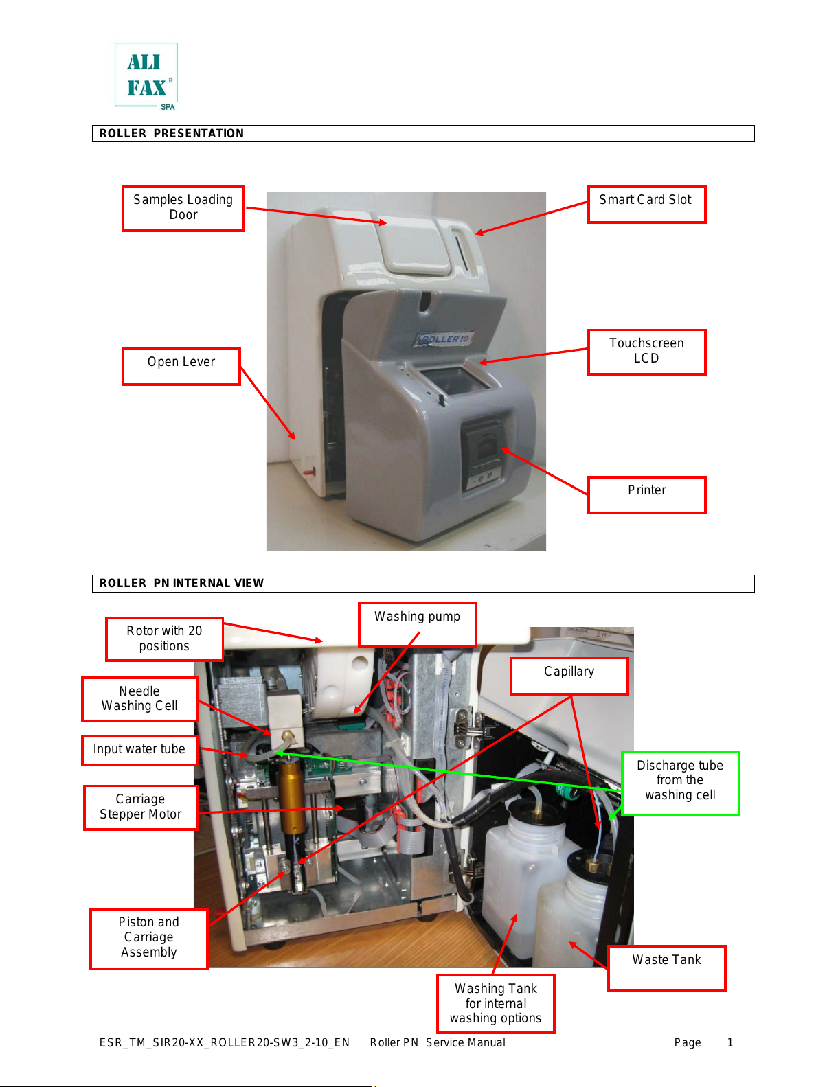
ROLLER PRESENTATION
ROLLER PN INTERNAL VIEW
Smart Card Slot
Touchscreen
LCD
Printer
Samples Loading
Door
Open Lever
Waste Tank
Piston and
Carriage
Assembly
Rotor with 20
positions
Capillary
Washing Tank
for internal
washing options
Discharge tube
from the
washing cell
Needle
Washing Cell
Input water tube
Washing pump
Carriage
Stepper Motor
All manuals and user guides at all-guides.com
Page 8
ESR_TM_SIR20-XX_ROLLER20-SW3_2-10_EN Roller PN Service Manual Page
2
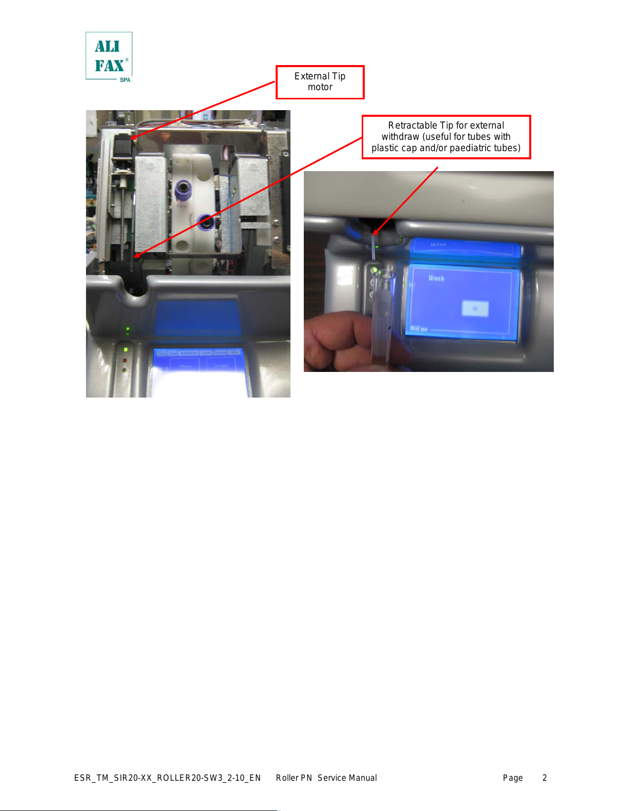
Retractable Tip for external
withdraw (useful for tubes with
plastic cap and/or paediatric tubes)
External Tip
motor
All manuals and user guides at all-guides.com
Page 9

ESR_TM_SIR20-XX_ROLLER20-SW3_2-10_EN Roller PN Service Manual Page
3
ROLLER REAR SIDE VIEW
To replace the fuses use the following procedure:
• Locate the fuses’ box
• Using a flat screwdriver push down the small tongue that keeps the box inside the
switch block and pull it out using a small pliers (if necessary).
• Remove completely the fuse box
• Remove completely the fuse box and replace BOTH
fuses (*)
• Insert again the fuse box inside the Main Switch block
pressing it firmly to assure the box’s tongue fits on the
hook.
(*)
The fuse which is placed in appliance inlet shall be replaced
only by a T5,0 A L 250 V dimensions 5x20 mm or T5,0 A H
250 V dimensions 5x20 mm.
A T5,0 Ampere fuse; it is suitable for both 115 and 230 Vac.
MAIN Switch and Power
Supply Plug.
Voltage: 115 – 230
Switch Mode Power Supply
(SMPS)
Power Supply
Fan Intakes
EBCR Serial
Port
HOST
Computer Serial
Port
USB Port (future
applications)
Main fuses box
Instrument cooling Fan
and Cooling Fan Intakes
All manuals and user guides at all-guides.com
Page 10
ESR_TM_SIR20-XX_ROLLER20-SW3_2-10_EN Roller PN Service Manual Page
4
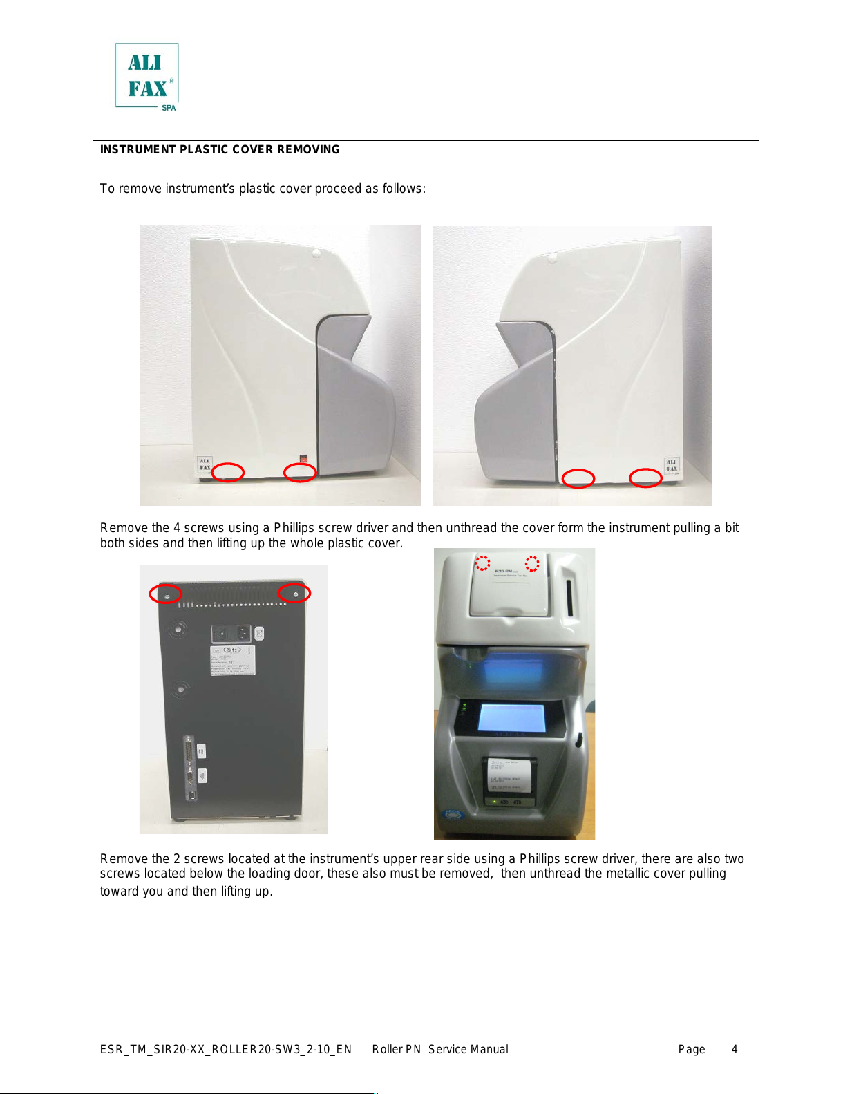
INSTRUMENT PLASTIC COVER REMOVING
To remove instrument’s plastic cover proceed as follows:
Remove the 4 screws using a Phillips screw driver and then unthread the cover form the instrument pulling a bit
both sides and then lifting up the whole plastic cover.
Remove the 2 screws located at the instrument’s upper rear side using a Phillips screw driver, there are also two
screws located below the loading door, these also must be removed, then unthread the metallic cover pulling
toward you and then lifting up
.
All manuals and user guides at all-guides.com
Page 11
ESR_TM_SIR20-XX_ROLLER20-SW3_2-10_EN Roller PN Service Manual Page
5
1.0 – ROLLER PN TECHNICAL SPECIFICATIONS ESR_PTDS_SI205_ROLLERPN_2-4_EN 2014-Janwary-31
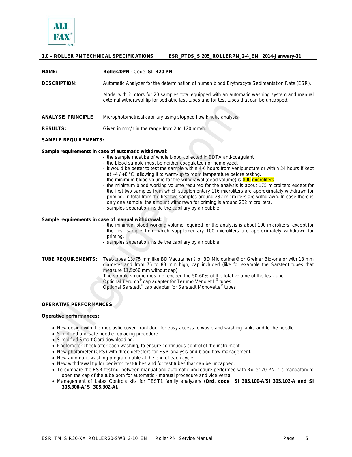
NAME: Roller20PN - Code SI R20 PN
DESCRIPTION: Automatic Analyzer for the determination of human blood Erythrocyte Sedimentat ion R ate (ESR).
Model with 2 rotors for 20 samples total equipped with an automatic washing system and manual
external withdrawal tip for pediatric test-tubes and for test tubes that can be unc apped.
ANALYSIS PRINCIPLE: Microphotometrical capillary using stopped flow kinetic analysis.
RESULTS: Given in mm/h in the range from 2 to 120 mm/h.
SAMPLE REQUIREMENTS:
Sample requirements in case of automati c withdrawal:
- the sample must be of whole blood collected in EDTA anti-coagulant.
- the blood sample must be neither coagulated nor hemolyzed.
- it would be better to test the sample within 4-6 hours from venipuncture or within 24 hours if kept
at +4 / +8 °C, allowing it to warm-up to room temperature before testing.
- the minimum blood volume for the withdrawal (dead volume) is 800 microliters
- the minimum bl ood working volume required for the analysis is about 175 microliters except for
the first two samples from which supplementary 116 microliters are approximately withdrawn for
priming. In total from the first two samples around 232 micr oliter s are withdrawn. In case there is
only one sample, the amount withdrawn for priming is around 232 microliters.
- samples separation inside the capillary by air bubble.
Sample requirements in case of manual withdrawal:
- the minimum blood working volume required for the analysis is about 100 microliters, except for
the first sample from which supplementary 100 microliters are approximately withdrawn for
priming.
- samples separation inside the capillary by air bubble.
TUBE REQUIREMENTS: Test-tubes 13x75 mm like BD Vacutainer® or BD Microtainer® or Greiner Bio-one or with 13 mm
diameter and from 75 to 83 mm high, cap included (like for example the Sarstedt tubes that
measure 11,5x66 mm without cap).
The sample volume must not exceed the 50-60% of the total volume of the test-tube.
Optional Terumo
®
cap adapter for Terumo Venojet II® tubes
Optional Sarstedt
®
cap adapter for Sarstedt Monovette® tubes
OPERATIVE PERFORMANCES
Operative performances:
• New design with thermoplastic cover, front door for easy access to waste and washing tanks and to the needle.
• Simplified and safe needle replacing procedure.
• Simplified Smart Card downloading.
• Photometer check after each washing, to ensure continuous control of the instrument.
• New photometer (CPS) with three detectors for ESR analysis and blood flow management.
• New automatic washing programmable at the end of each cycle.
• New withdrawal tip for pediatric test-tubes and for test tubes that can be uncapped.
• To compare the ESR testing bet ween manual and automatic procedure perfor med with Roller 20 PN it is mandator y to
open the cap of the tube both for automatic - manual procedur e and vice versa
• Management of Latex Controls kits for TEST1 family analyzers (Ord. code SI 305.100-A/SI 305.102-A and SI
305.300-A/ SI 305.302-A).
All manuals and user guides at all-guides.com
all-guides.com
Page 12
ESR_TM_SIR20-XX_ROLLER20-SW3_2-10_EN Roller PN Service Manual Page
6
Automatic withdraw al:
• Samples mixing can be programmed in three speeds ( 60, 32 and 26 RPM) and in number of rotations, from 2 to 1000
rotations (recommended 32 RPM @ 140 rotations, about 4,2 minutes mixing).
• First result available after 4,2 minutes (mixing) and 30 seconds (analysis), the other results are given every 30 seconds
each; 20 samples processed in about 10 minutes (120 samples per ho ur) without considering the time taken for
loading and unloading of test-tubes from the instrument.
With Syringe fast enabled, mixing time is the same, but analysis time reach 24 seconds per sample, and so 20
sample are processed in about 8 minutes.
The above throughput could be delayed in case of connection to the Host Computer with reply output time more than
1 second.
Manual withdrawal:
• Samples mixing can be programmed in three speeds ( 60, 32 and 26 RPM) and in number of rot ations, from 2 to 1000
rotations (recommended 32 RPM @ 140 rotations, about 4,2 minutes mixing).
• First result available after 4,2 minutes (mixing) and 30 seconds (analysis), the other results are given every 30 seconds
each. This times are cons idered without including the time taken for loading and unloading the test-tubes from the
instrument and also for uncapping and recapping the test-tubes..
The above operation could be delayed in case of connection to the Host Computer with reply output time mor e than 1
second.
Error notice:
The instrument in case of error or malfunc tion, reports this situation with a spec ific message on the screen plus with an
acoustic intermittent signal of 62,5 dBA.
CAPACITY: max 20 samples/session
ANALYTICAL PERFORMANCES (obtained with 3 ml test-tubes):
Agreement with TEST1: R
2
= 0.91
Repeatability: mean CV% = 5.7% on the whole range 2 - 120 mm/h
Reproducibility: mean CV% = 5.1% on the whole range 2 - 120 mm/h
Stability of samples stored for 24 h at ro om temperature:
In order to view the effects of different methods of storage on the ESR value, 272 K
3
EDTA-
anticoagulated whole blood samples, some of which have been stored at 4 °C and some others at
room temperature, have been analyzed after 4 hrs and after 24 hrs on TEST1 device. Good
correlation was found between the results taken at 4 hrs and those taken at 24 hrs on the s am pl es
stored at 4 °C (r=0.980). Those stored at room temperature did not correlate quite as well as
those stored at 4 °C, but still had very good correlation (r=0.917)
(1)
.
METHOD LIMITATIONS: 1. The erythroc yte sedimentation rate is a phenomenon confined to fresh blood and transient
(2)
,
not a hematic matrix component (at corpuscular / molecular level). The procedures used to
determine the ESR cannot be calibrated as they are susceptible to a variety of errors
(temperature, hematocrit, erythrocyte mean corpuscular volume, plas ma viscosity, etc.)
(2)
. Based
on the acquired experience,TEST1 family instruments (TEST1, MicroTEST1, Roller), are
limitedly affected by these variables. For this reason it is possible to observe instrument
performances deviations compared to other procedures if the abov e variables are not taken into
account.
2. Erythrocyte sedimentation remains an only partly understood phenomenon….is a nonspecif ic
reaction (from a clinical point of view)…
(2)
that is affected by several technical aspects
(3)
. The
ESR is often normal in patients with cancer...
(3)
.
International guidelines for diagnosis and management of multiple myeloma do not m ention the
Erythrocyte Sedimentation Rate
(4)
. It is then necessary to point out that even though TEST1
analytical performances have been confirmed in patients affect ed by multiple myeloma
(5,6)
, there
have been some cases of patients affected by multiple myeloma in which TEST 1 has reported
clinically negative ESR values in comparison to other methods. Based on this experience there
could be cases in which Roller gives low ESR results likewise TEST1 in presence of Multiple
Myeloma.
It is then highly recommended to perform other tests t ogether with the ESR in the diagnosis of
cancer since a normal ESR value is not enough to exclude that the patient is not affected by this
pathology.
All manuals and user guides at all-guides.com
Page 13

ESR_TM_SIR20-XX_ROLLER20-SW3_2-10_EN Roller PN Service Manual Page
7
Furthermore in presence of this dis ease it is possible to observe deviations form other m ethods
since other phenomena in addition to the rouleaux format ion can contribute to the sediment ation
like for example amorphous aggregates formation (crystallization of paraproteins or mineral
materials like calcium) resulting from bone tissue alteration.
3. Samples mixing is programmed at the beginning of the analysis with the purpose of
disaggregating erythrocytes. An inefficient disaggregation or micro-clot s presence can affect the
result given by the instrument that in fact measures erythrocytes aggregation kinetics.
4. The above instrument performances have been obt ained using test tubes with a capacity of 3
ml and 13x75 mm size with K
3
EDTA anticoagulant. The use of such tubes opti mizes the mixing
phase and consequently the results reproducibility.
ENVIRONMENTAL AND PHYSICAL SPECIFICATIONS
Permissible environment conditions for operation: Temp.: from 10 to +30°C
Humidity: from 15% to 85% - no dew
Permissible environment conditions for transportation
and storage: Temp.: from -20 to +65°C
Humidity : from 5% to 95% - no dew
Size and weight: Width: 240 mm
Depth: 380 mm
Height: 450 mm
Weight: 16 Kg
ELECTRICAL SPECIFICATIONS
Voltage: 115 - 230 Vac Power consumption: 115 VA
Switch Mode Power Supply (SMPS) Switch on cons: 132 W
Frequency: 50/60 Hz
Classification: Class I (EN61010-1 – IEC 1010-1 – CEI 66-5)
OTHER OPERATIVE SPECIFICATIONS:
Heat dissipation in the environment: about 230 BTU/hour
Noise: at low speed mixing: 55,0 db(A)
at high speed mixing: 50,6 db(A)
Maximum rated altitude: 3000 mt asl
Communication: 2 serial RS232 ports located on the rear side of the instrument:
Port 1 (DB25) is dedicated to connect an external scanner
Port 2 (DB) is dedicated to connect the instrument to an Host Computer
1 USB serial ports (for future applications)
Functioning: The instrument is designed to rem ain switched ON 24 hours a day, it is however suggested
to switch it off at the end of the working day, applying previously a washing procedure using
3 washing tube to ensure a long capillary’s and sensors’ life.
Restrictions: Indoor user appliance
Rated pollution degree: Grade 2
Working life of the instrument: 10 years (if maintenance is done correctly)
All manuals and user guides at all-guides.com
Page 14

ESR_TM_SIR20-XX_ROLLER20-SW3_2-10_EN Roller PN Service Manual Page
8
INTERNAL QUALITY CONTROL
Latex Controls: Latex Controls for TEST1 family analyzers allow the control of the calibration stability of
TEST1, MicroTEST1; Roller and JO-PLUS. They are available in two kinds of test tubes:
♦ 13x75 mm Greiner: Latex Controls (6 tests) - code SI 305.100-A;
Latex Controls (30 tests) – code SI 305.300-A
♦ 11,5x66 mm Sarstedt: Latex Controls (6 tests) - code SI 305.102-A;
Latex Controls (30 tests) - code SI 305.302-A
TEST1 Family Quality Control: it is a software (code SI195620) designed to collect and process the data from one or more
TEST1 family analyzers (TEST1, MicroTEST1, Roller) for evaluating their performances.
CONSUMABLES
Printer Paper: Thermal roller paper 58 +0/-1 mm x Max 32 mm external diameter
Smart Card: Conform to ISO 7816-1 specifications – 85.6 x 54 x 0.8 mm
Coded using SIRE Analytical Systems / Alifax Group proprietary algorithm
Available for 1,000 (Ord. code SI 195901) - 4,000 (Ord. code SI 195904) - 10,000 (Ord.
code SI 195910) - 20,000 (Ord. code SI 195920) tests / Universal Card for TEST1 family
analyzers (TEST1; MicroTEST1; Roller).
Waste Tank: 500 ml plastic waste tank with screw cap.
Wash Tank: 500 ml plastic waste tank with screw cap (Available only on SI R20 PN Model)
OPTIONAL AVAILABLE TOOLS
Patient identification: External CCD bar-code reader (SI195820)
REFERENCES:
1. E. Heverin (Galway-Mayo Institute of Technology, Ireland): ”Comparison of the Westergren method versus
the TEST1 technique for determining the Eryth rocyte Sedimentation Rate”, May 2002, private communicati on
2. NCCLS “Reference and Selected procedure for the Erythrocyte Sedimentation rate (E SR) Test; Approved
Standard-Fourth Edition”, Vol. 20 No. 27
3. Sox HC, Liang MH: “The Erythrocyte Sedimentation Rate”, Annals of Internal Medicine 1986; 105:515-523.
4. NCCN (National Comprehensive Cancer Network) Clinical Practice Guidelines in Oncology “Multip le
Myeloma” (V.I.2007)
5. Ajubi et al.: “Determination of the lenght of sedimentation reaction in blood using the TEST1 system:
comparison with the Sedimatic 100 method, turbidimetric fibrinogen levels, and the influence of M-proteins”,
Clin Chem Lab Med 2006; 44 (7): 904-906
6. Mercurio S. et al.: “Comparison between two methods for ESR measure in patients affect ed by myeloma”,
37° SIBioC National Congress, 11-14 October 2005 Rome.
All manuals and user guides at all-guides.com
Page 15
ESR_TM_SIR20-XX_ROLLER20-SW3_2-10_EN Roller PN Service Manual Page
9
7.
2.0 - WARNINGS
The manufacturer does not assume any responsibility for eventual damages to persons or things due to
improper use of the instrument, installation not in compliance with the manufacturer's specifications, use
of the instrument not in security, use of not suitable materials regarding those specified in the user's
manual, use of the instrument for various scopes different from those for which it has been designed and
built, use of the instrument by not expert staff person or however non-authorized to the use of the
instrument and/or in case the sanitization procedure will not be carried on if required.
Is absolutely forbidden exchanging any electronic board from one instrument to another instrument.
This instrument is not intended for use by persons with reduced physical, mental and sensorial
capabilities or lack of experience and knowledge, unless they have been given supervision or preliminary
instructions for the use of the analyzer by a person responsible for their safety.
The instrument has to be installed on a dry surface sheltered from sun light to avoid sun rays hit the door
sensor when the door is open generating unplanned consequences.
The sy ringe group, li ke the carriage group (Roller 20 PN) moves on “self-lubricating „ sliding guides it is
not therefore necessary to lubricate or to add to any kind of oil or grease to the guides.
Check the inst rum ent is connected to an efficiently ground before its use.
Check the waste tank level before starting the measures, empty or replace the waste tank, if filled to
security level, following the standard safety procedures in use in the laboratory .
Switch to ON the instrument and wait at least 20 minutes before its use to reach the thermal circuitry
equilibrium.
Check if the tube contains at least 1 ml of blood and verify that the blood is not neither haemolysed nor
coagulated. The optimal performance of the instrument is obtained using exclusively blood samples
withdrawn in EDTA anticoagulant (K2 or K3)
In case of use of the external withdrawing tip, it is mandatory to clean it following the washing procedure
in order to avoid blood dries inside the tip causing the formation ob blood clogs inside it. The tip must be
washed within 10 minutes before last sample analysis.
The blood samples must remain capped (don’t uncap and recap them since the instrument’s
performances would be affected Except if analyzed using the external windrowing probe).
Use preferably tubes with a capacity of 3 ml verifying that the sample volume does not exceed the 50-
60% of the total volume of the test-tube to optimise the sample homogenisation. The use of such tubes
optimizes the mixing phase and consequently the results reproducibility.
Start analysis within 2-4 hours from venipuncture, otherwise keep the samples in refrigerator at + 4÷8 °C
for a maximum of 24 hours. If the samples have been conserved in refrigerator at + 4÷8 °C. it is
necessary to leave them at room temperature at least for 30 minutes before executing t hei r anal ysis
Fol l ow the "WASHING PROCEDURE" for a good maintenance of the instrument.
For professional in vitro medical diagnostic use only.
The i nst rument is designed for indoor uses only
If metallic or electronic parts are damaged, ask for the immediate replacing of them. This will be done
supplying original spare parts especially for the mains parts (power cord, mains group, power switch) .
The instrument, can be exposed to potential infective materials. It’s, therefore, compulsory to adopt all the
precautions and the necessary warnings, in accordance with national laws, which apt to avoid any
physical contact.
If the instrument has been stored in cold places, wait at least 30 minutes before switching ON the
instrument for the first time in order to avoid eventual damages due to dew presence on internal parts of
the instrument.
Keep away any kind of objects, liquids, or substances not required for the instrument’s use from the
instrument.
Switch OFF the instrument before connecting any external peripheral as external bar code readers,
printer cables and/or RS232 serial cables.
All manuals and user guides at all-guides.com
Page 16

ESR_TM_SIR20-XX_ROLLER20-SW3_2-10_EN Roller PN Service Manual Page
10
Use only original spare parts supplied by the manufacturer.
Do not remove the panels neither camper the reading sensor. The maintenance operations must be
carried out only by technical personnel authorized by the manufacturer.
For your safety, if any parts are damaged, ask for the immediate replacing with original spare parts,
specially for the parts connected to mains (power cord, fuse-holder and mains switch …)
Prior to install and use the instrument for the first time, it is suggested an evaluation of the
electromagnetic environment
Do not use the instrument in proximity of sources of strong electromagnetic radiations (e.g. mobiles,
CB’s, radio transmitting units and similar or unshielded intentional RF sources) as these may interfere
with the proper operation of the instrument
In order to avoid possible mistakes in the Query-Host communication and/or the transmission of patient
ID to the Host computer, it is recommended the use of bar-code codification which includes the “check-
digit” option in its protocol.
Battery for Unit Interface board SI205001 (S25.001x) is Kinetic #MH60B3AL3; Ni MH; 3,6V 60 mAh
Instrument is compliant with IEC 61326 emissions and immunity requirements
THE FOLLOWING LABELS ARE STUCK AS WARNINGS ON THE INSTRUMENT AND MUST NOT BE REMOVED..
PROCEDURE OF INSTRUMENT DISPOSAL AT THE END OF ITS OPERATIONAL LIFE
As stated on European directive 2002/ 96/CE relative on wast e of electrical and electronic equipment (WEEE) appropriate
measures should be adopted to minimize the disposal as unsorted municipal w aste and to achieve a high level of separate
collection of WEEE, according to the applicable local laws and rules.
The crossed-out wheeled bin symbol on s ide, placed also close to the plate of the apparatus , points out the necessity of the
separate collection of (WEEE).
The separate collection of this instrument at the end of it s life is organized and managed by You as Importer . The user then,
will contact You and follow the system you have adopted in compliance with your national requirements.
The unauthorized disposal will be pursued according to the local l aws and the rules in the nation of use. T he penalties will be
effective, proportionate and dissuasive.
All manuals and user guides at all-guides.com
all-guides.com
Page 17
ESR_TM_SIR20-XX_ROLLER20-SW3_2-10_EN Roller PN Service Manual Page
11
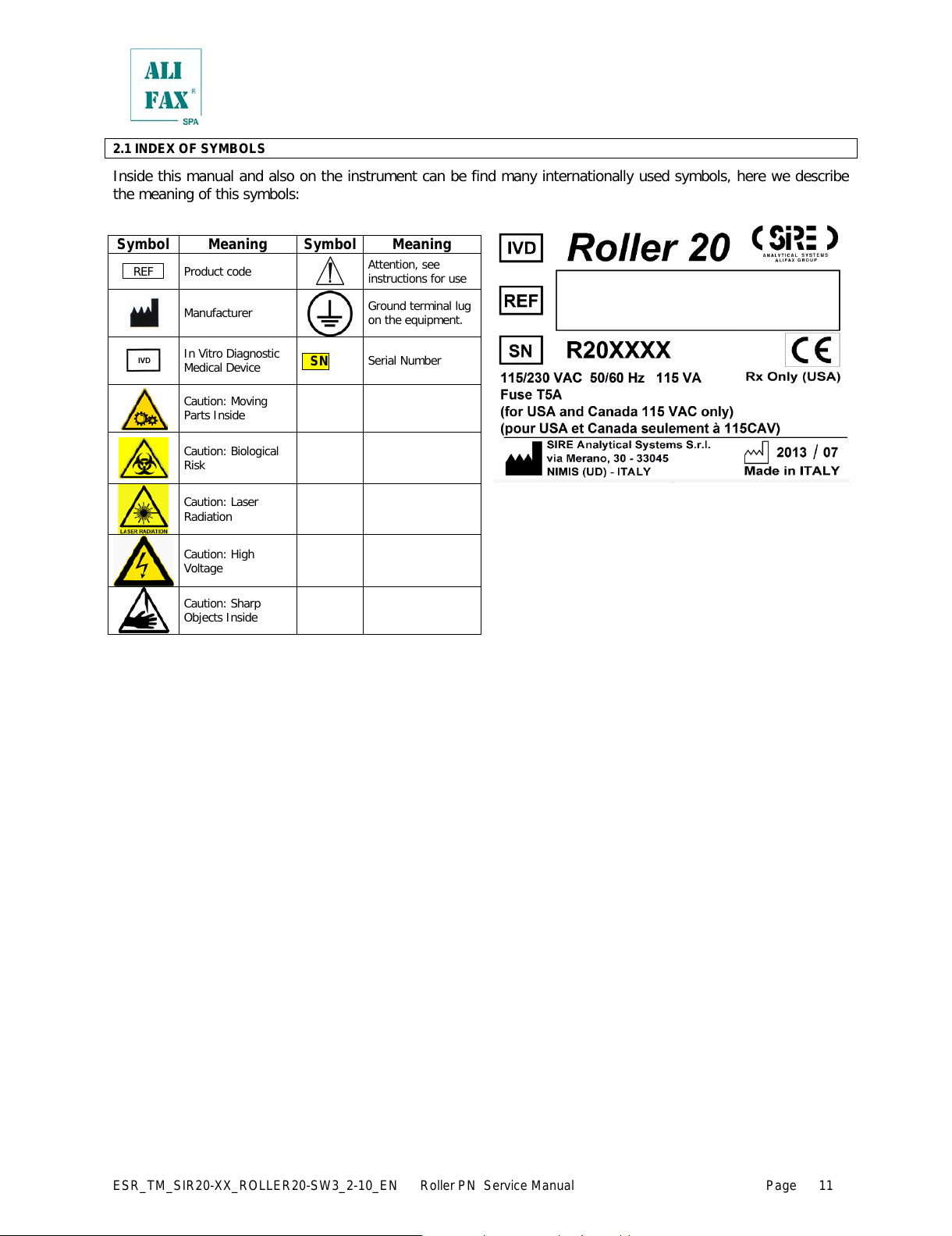
2.1 INDEX OF SYMBOLS
Inside this manual and also on the instrument can be find many internationally used symbols, here we describe
the meaning of this symbols:
Symbol
Meaning
Symbol
Meaning
_ REF _ Product cod e
Attention, see
instructions for use
Manufacturer
Ground terminal lug
on the equipment.
In Vitro Diagnostic
Medical Device
SN
Serial Number
Caution: Moving
Parts Inside
Caution: Biological
Risk
Caution: Laser
Radiation
Caution: High
Voltage
Caution: Sharp
Objects Inside
All manuals and user guides at all-guides.com
Page 18
ESR_TM_SIR20-XX_ROLLER20-SW3_2-10_EN Roller PN Service Manual Page
12
3.0 - UNPACKING AND INSTALLATION
Personnel qualified for the installation
The installation of this apparatus cannot be done from the final user, but it must be done only from a qualified
technician authorized from the manufacturer, to avoid the invalidation of the guarantee. In this way, each possible
problematic that it could jeopardize the operation of the instrument of its results, can be evaluated and eventually
resolved from fully trained personnel for these eventualities.
Packing control
The instrument comes packed in a carton box. Before proceeding with the unpacking, perform a control of the
packing, verifying the sides and the corners of the box for possible damages. Any damage must be reported on
the Installation and Testing Form, enclosed to the documentation of the instrument .
Unpacking
Open the pack from the top, extracting the first box that contains the accessories and then extract the instrument.
Place the instrument on the table for allowing the removal of the protective nylon foil. Report any damage of
instrument plastic covers on the Installation and Testing Form.
Packing control contents
Beyond the instrument, the pack contains a flat box with all the necessary accessories for the correct installation
and the correct operation of the instrument; all these accessories are exactly listed on the Packing List form and
they could vary according to the instrument configuration.
The content of the packing and the accessories box must be at least the following:
no. 01 ROLLER 10 instrument
no. 01 operative manual (this one that you are reading now)
no. 01 Packing List form
no. 01 Installation and Testing form
no. 01 Declaration of CE compatibility
no. 01 Final Testing certificate
no. 01 mains cable
no. 02 rolls of thermal paper (one is installed, one into the accessories box)
no. 02 waste tank (one is installed, one into the accessories box)
no. 02 mains fuses
Moreover, in accordance with the configuration, the following accessories can be present:
no. 01 external bar-code reader (EBCR)
Refer however to the Packing List form for the control of the packing and accessories box contents, signaling any
difference between the pack contents and those listed on the Packing List on the Installation and Testing form.
This will help us to guarantee better controls during manufacturing and packing.
Instrument installation
The instrument must be installed on a working table able to support its weight (about 16 Kg) and providing
enough space on the right side to reach the power supply switch, located on the high back side of the instrument.
Choose a location sheltered from the sun direct light and far from sources of moisture, to allow a reliable
operation and a better duration of instrument operational life.
Besides, provide at least 10 cm of clearance on the back side of the instrument to allow the connection of the
mains cable and eventually the data cable for the connection with the Lab Informativ e System (LIS).
Avoid if possible the connection to mains through plug adapters and choose an electrical outlet far from any
strong impulsive voltages, usually generated from centrifuges, refrigerators, elevators and freight el evators.
As reported on the technical specifications, the instrument can handle a voltage from 85 to 256 Vac thus it is not
necessary a voltage selector.
Before power on the instrument, control also the presence and the connection of the waste tank, opening the
front door of the instrument.
After above controls, proceed with the lighting of the instrument, verifying that all the initialization procedure is
correctly completed as described on the Technical Manual of the instrument.
Any possible anomaly must be signaled on the Installation and Testing form.
All manuals and user guides at all-guides.com
Page 19
ESR_TM_SIR20-XX_ROLLER20-SW3_2-10_EN Roller PN Service Manual Page
13
4.0 – PRELIMINARY CHECKS, FIRST INSTALLATION AND SOFTWARE UPGRADE
Before switching on the instrument is MANDATORY to
• check out the waste tank level and empty or replace it if filled to security level, following the standard
safety procedures in use in the laboratory.
• if it is installed check the wash tank level and fill up with distillate water.
After switching on the instrument is MANDATORY to
• Check the availability of thermal paper
• In case of use of Sarstedt tubes, please refer to chapter 9.5.6.a
• Wait 20 minutes to allow the reading unit reach the thermal stability
For the first installation, please refer to chapter 10
For software upgrade, please refer to chapter 11
5.0 – WASTE TANK REPLACE / EMPTY
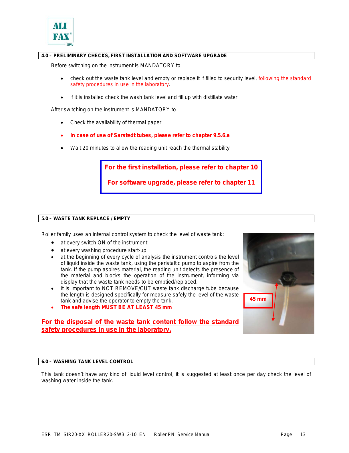
Roller family uses an internal control system to check the level of waste tank:
• at every switch ON of the instrument
• at every washing procedure start-up
• at the beginning of every cycle of analysis the instrument controls the level
of liquid inside the waste tank, using the peristaltic pump to aspire from the
tank. If the pump aspires material, the reading unit detects the presence of
the material and blocks the operation of the instrument, informing via
display that the waste tank needs to be emptied/replaced.
• It is important to NOT REMOVE/CUT waste tank discharge tube because
the length is designed specifically for measure safely the level of the waste
tank and advise the operator to empty the tank.
• The safe length MUST BE AT LEAST 45 mm
For the disposal of the waste tank content follow the standard
safety procedures in use in the laboratory.
6.0 – WASHING TANK LEVEL CONTROL
This tank doesn’t have any kind of liquid level control, it is suggested at least once per day check the level of
washing water inside the tank.
45 mm
All manuals and user guides at all-guides.com
Page 20
ESR_TM_SIR20-XX_ROLLER20-SW3_2-10_EN Roller PN Service Manual Page
14
7.0 – INCREASE AVAILABILITY TEST USING THE SMART CARD
Roller has been developed to analyze up to six blood parameters. This means that according to the blood
desired parameters to be analyzed, will be available different test cards and each single card will upgrade only
the tests for which has been programmed.
Independently from the kind of test, the warning threshold is the same for all them, in other words, setting the
warning level to a specific value, means that that value will be the reference for all type of tests that has been
charged.
When the prefixed threshold alarm is reached by ESR parameter, display will show a warning message requiring
to increase the availability. All the other test will be also automatically increased.
Instrument allows to go in negative availability only one time; supposing the ESR availability is 1,
instrument allows to run up to 20 samples and goes in a negative availability of -19; at the next test
increase, the availability of test will be discounted by 19 tests.
WARNING!! If at the end of cycle no one parameter has a positive residual availability, the instrument will set
itself in idle and will not allow any kind of activities up when the availability will be increased using the specific
smart card.
To increase availability, it is necessary to be in MAIN SCREEN (if the card is inserted while the display shows a
different menu, it will not considered) then insert the appropriate smart card in the reading slot, facing the card
with the integrated circuit toward the left side, like displayed on the picture on chapter 7.1
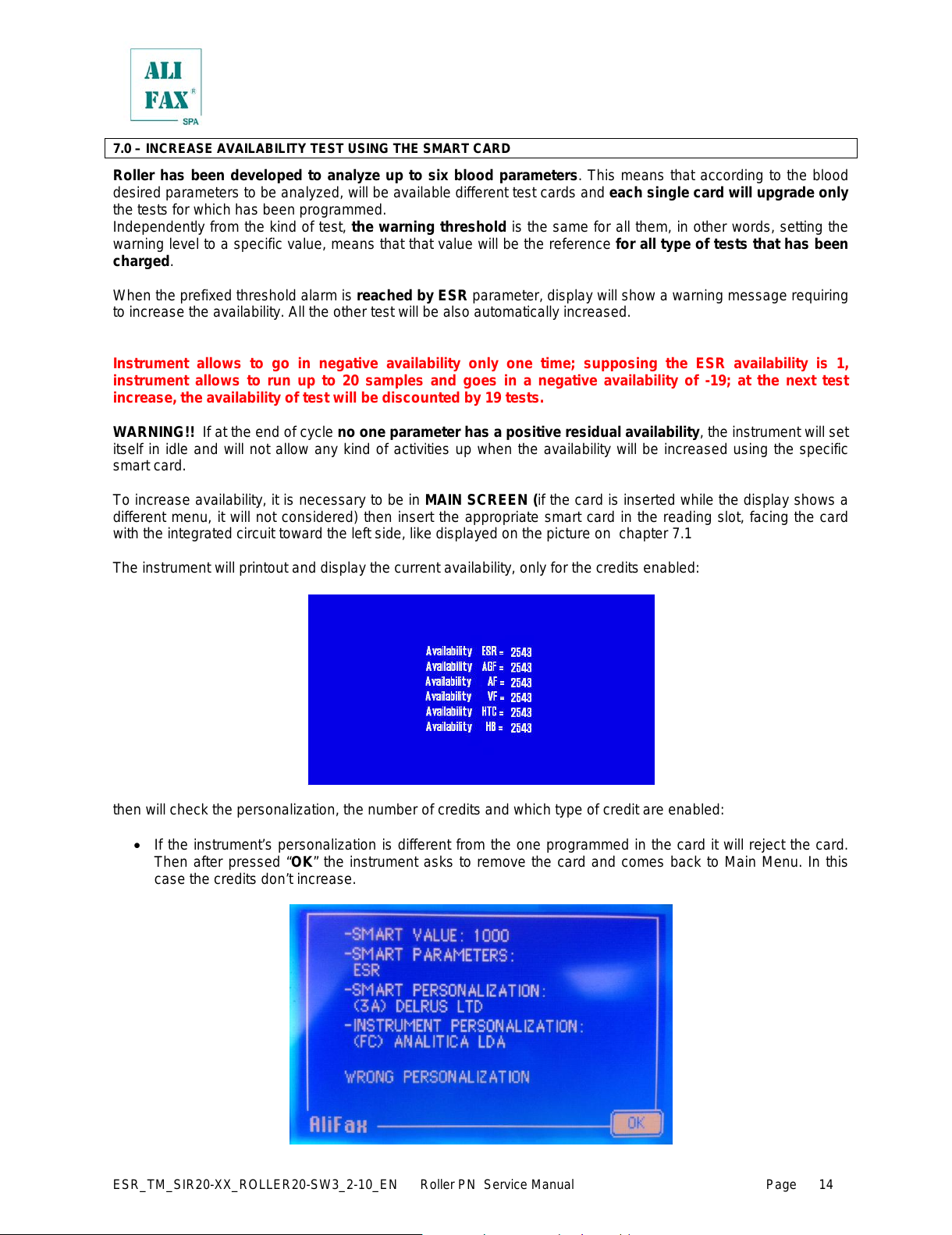
The instrument will printout and display the current availability, only for the credits enabled:
then will check the personalization, the number of credits and which type of credit are enabled:
• If the instrument’s personalization is different from the one programmed in the card it will reject the card.
Then after pressed “OK” the instrument asks to remove the card and comes back to Main Menu. In this
case the credits don’t increase.
All manuals and user guides at all-guides.com
Page 21
ESR_TM_SIR20-XX_ROLLER20-SW3_2-10_EN Roller PN Service Manual Page
15
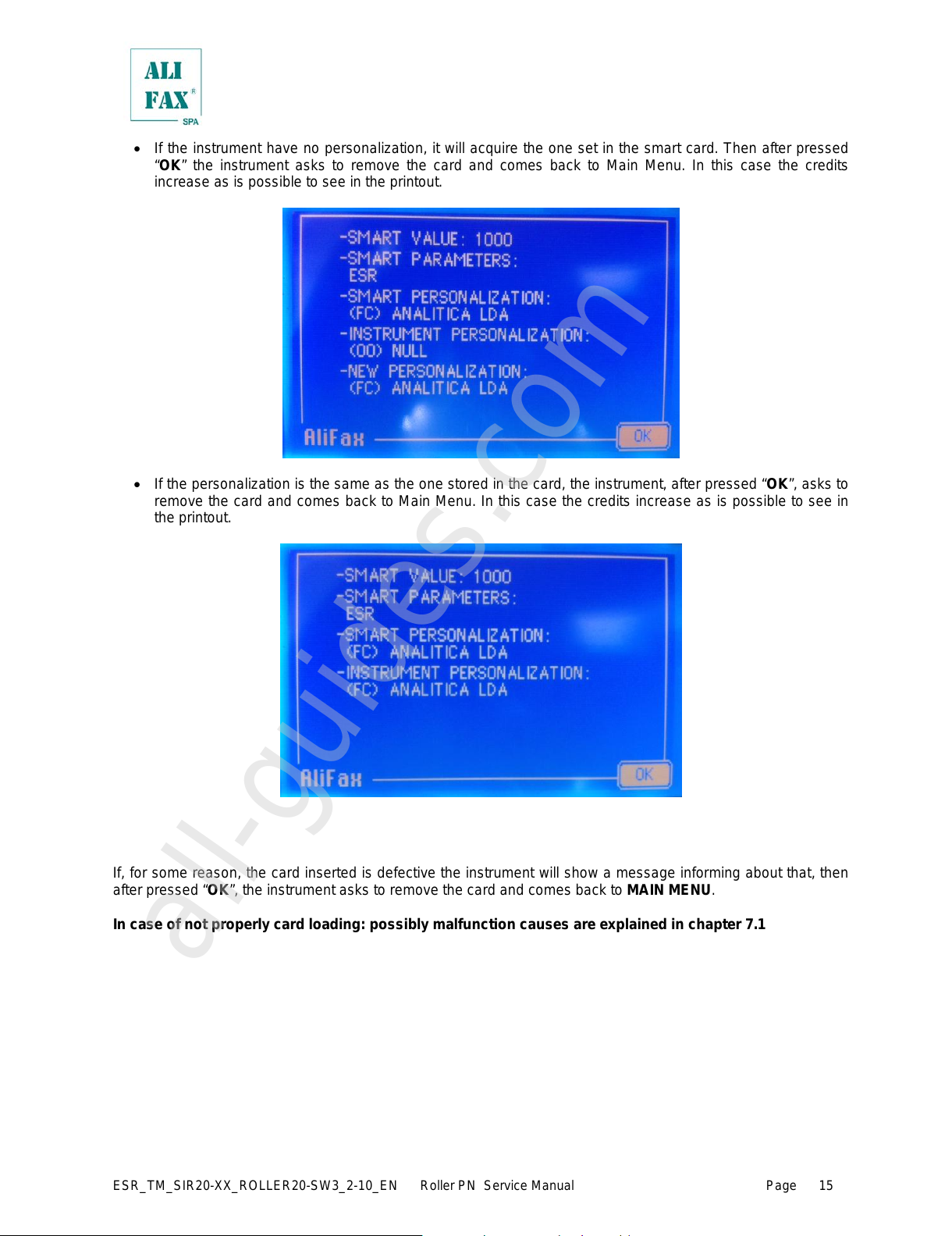
• If the instrument have no personalization, it will acquire the one set in the smart card. Then after pressed
“OK” the instrument asks to remove the card and comes back to Main Menu. In this case the credits
increase as is possible to see in the printout.
• If the personalization is the same as the one stored in the card, the instrument, after pressed “OK”, asks to
remove the card and comes back to Main Menu. In this case the credits increase as is possible to see in
the printout.
r
If, for some reason, the card inserted is defective the instrument will show a message informing about that, then
after pressed “OK”, the instrument asks to remove the card and comes back to MAIN MENU.
In case of not properly card loading: possibly malfunction causes are explained in chapter 7.1
All manuals and user guides at all-guides.com
all-guides.com
Page 22
ESR_TM_SIR20-XX_ROLLER20-SW3_2-10_EN Roller PN Service Manual Page
16
7.1 – SMART CARD ERRORS
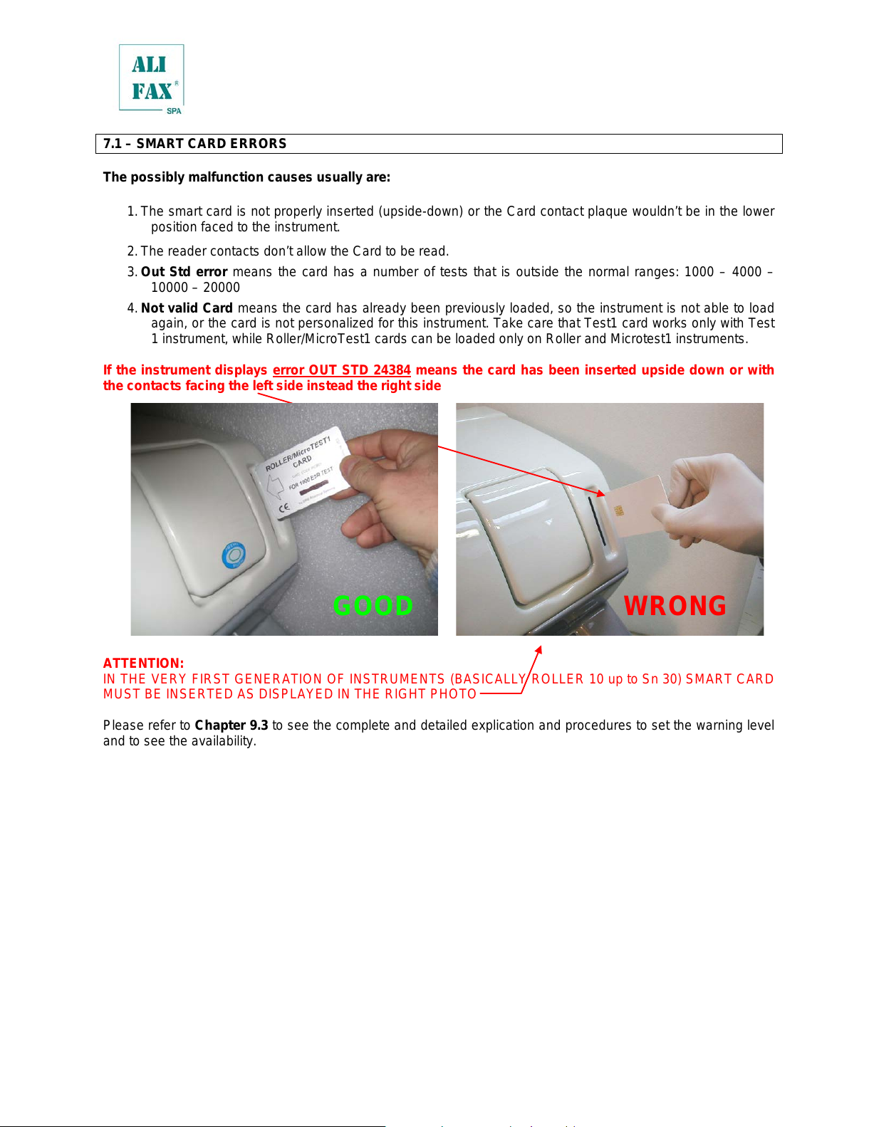
The possibly malfunction causes usually are:
1. The smart card is not properly inserted (upside-down) or the Card contact plaque wouldn’t be in the lower
position faced to the instrument.
2. The reader contacts don’t allow the Card to be read.
3. Out Std error means the card has a number of tests that is outside the normal ranges: 1000 – 4000 –
10000 – 20000
4. Not valid Card means the card has already been previously loaded, so the instrument is not able to load
again, or the card is not personalized for this instrument. Take care that Test1 card works only with Test
1 instrument, while Roller/MicroTest1 cards can be loaded only on Roller and Microtest1 instruments.
If the instrument displays error OUT STD 24384 means the card has been inserted upside down or with
the contacts facing the left side instead the right side
ATTENTION:
IN THE VERY FIRST GENERATION OF INSTRUMENTS (BASICAL LY ROLLER 10 up to Sn 30) SMART CARD
MUST BE INSERTED AS DISPLAYED IN THE RIGHT PHOTO
Please refer to Chapter 9.3 to see the complete and detailed explication and procedures to set the warning level
and to see the availability.
7.2 – MULTIPARAMETRIC CARDS
With the use of multiparametric cards is possible to activate the analysis of one or more parameters.
At the moment is available the classical ESR card and the ESR + AnF Factor
GOOD
WRONG
All manuals and user guides at all-guides.com
Page 23
ESR_TM_SIR20-XX_ROLLER20-SW3_2-10_EN Roller PN Service Manual Page
17
7.2 – PAPER ROLL LOADING - REPLACEMENT
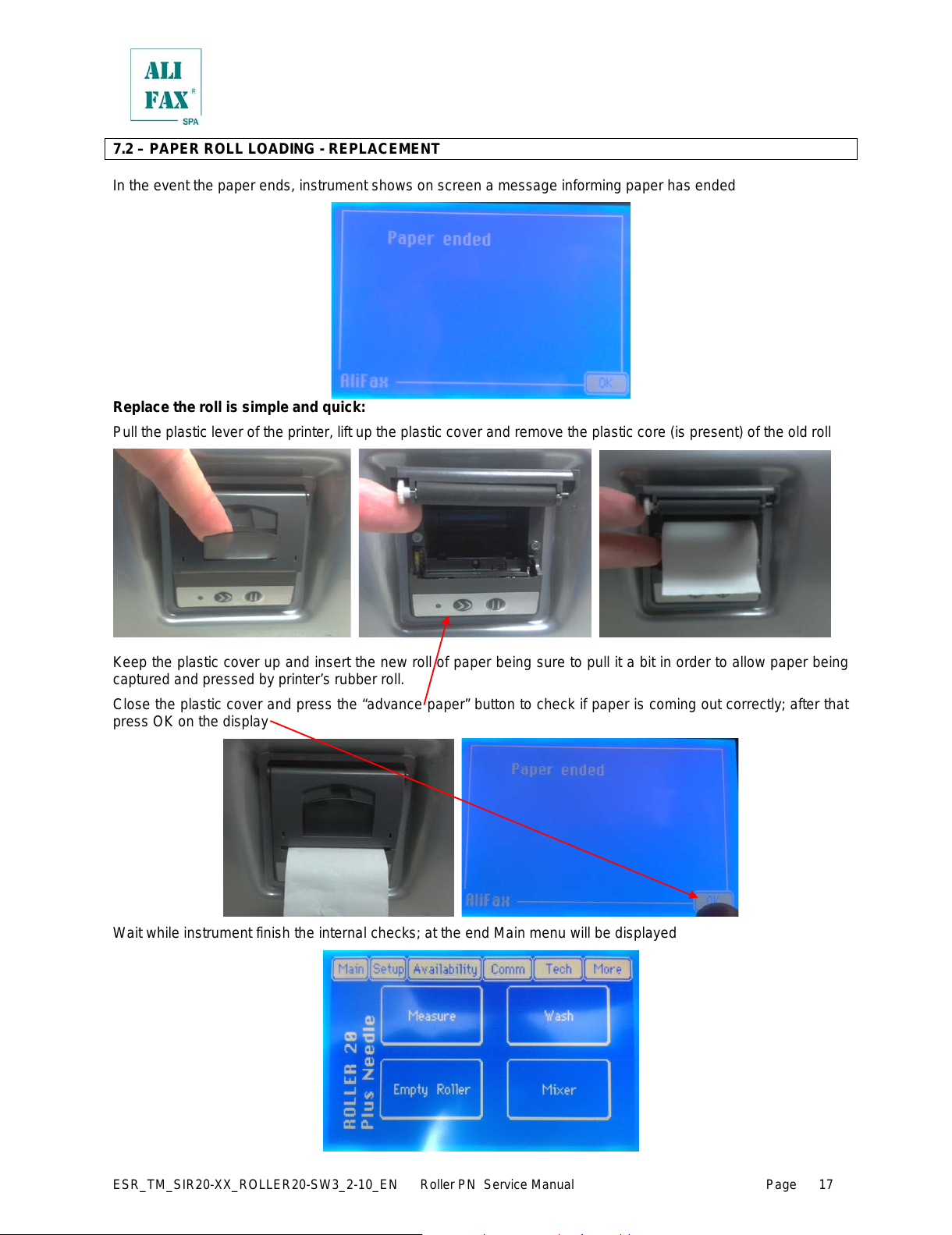
In the event the paper ends, instrument shows on screen a message informing paper has ended
Replace the roll is simple and quick:
Pull the plastic lever of the printer, lift up the plastic cover and remov e the plastic core (is present) of the old roll
Keep the plastic cover up and insert the new roll of paper being sure to pull it a bit in order to allow paper being
captured and pressed by printer’s rubber roll.
Close the plastic cover and press the “advance paper” button to check if paper is coming out correctly; after that
press OK on the display
Wait while instrument finish the internal checks; at the end Main menu will be displayed
All manuals and user guides at all-guides.com
Page 24
ESR_TM_SIR20-XX_ROLLER20-SW3_2-10_EN Roller PN Service Manual Page
18
8.0 – SWITCH ON
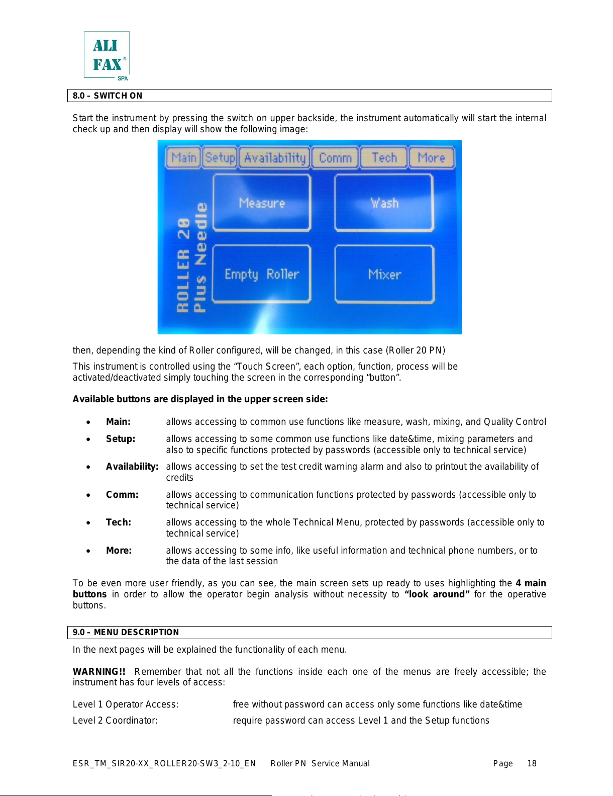
Start the instrument by pressing the switch on upper backside, the instrument automatically will start the internal
check up and then display will show the following image:
then, depending the kind of Roller configured, will be changed, in this case (Roller 20 PN)
This instrument is controlled using the “Touch Screen”, each option, function, process will be
activated/deactivated simply touching the screen in the corresponding “button”.
Available buttons are displayed in the upper screen side:
• Main: allows accessing to common use functions like measure, wash, mixing, and Quality Control
• Setup: allows accessing to some common use functions like date&time, mixing parameters and
also to specific functions protected by passwords (accessible only to technical service)
• Availability: allows accessing to set the test credit warning alarm and also to printout the availability of
credits
• Comm: allows accessing to communication functions protected by passwords (accessible only to
technical service)
• Tech: allows accessing to t he whole T echnical M enu, protected by passwords (accessible only to
technical service)
• More: allows accessing to some info, like useful information and technical phone numbers, or to
the data of the last session
To be even more user friendly, as you can see, the main screen sets up ready to uses highlighting the 4 main
buttons in order to allow the operator begin analysis without necessity to “look around” for the operative
buttons.
9.0 – MENU DESCRIPTION
In the next pages will be explained the functionality of each menu.
WARNING!! Remember that not all the functions inside each one of the menus are freely accessible; the
instrument has four levels of access:
Level 1 Operator Access: free without password can access only some functions like date&time
Level 2 Coordinator: require password can access Level 1 and the Setup functions
All manuals and user guides at all-guides.com
Page 25
ESR_TM_SIR20-XX_ROLLER20-SW3_2-10_EN Roller PN Service Manual Page
19
Level 3 Technical Service: require a password, allow access to all functions; this password is ONLY
for Technical Service and Alifax Manufacturing dept.
9.1 – MAIN MENU
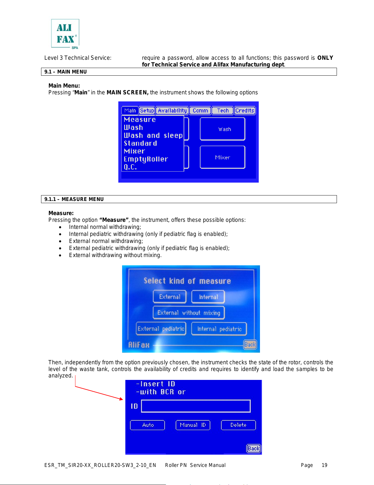
Main Menu:
Pressing “Main” in the MAIN SCREEN, the instrument shows the following options
9.1.1 – MEASURE MENU
Measure:
Pressing the option “Measure”, the instrument, offers these possible options:
• Internal normal withdrawing;
• Internal pediatric withdrawing (only if pediatric flag is enabled);
• External normal withdrawing;
• External pediatric withdrawing (only if pediatric flag is enabled);
• External withdrawing without mixing.
Then, independently from the option previously chosen, the instrument checks the state of the rotor, controls the
level of the waste tank, controls the availability of credits and requires to identify and load the samples to be
analyzed.
All manuals and user guides at all-guides.com
Page 26
ESR_TM_SIR20-XX_ROLLER20-SW3_2-10_EN Roller PN Service Manual Page
20
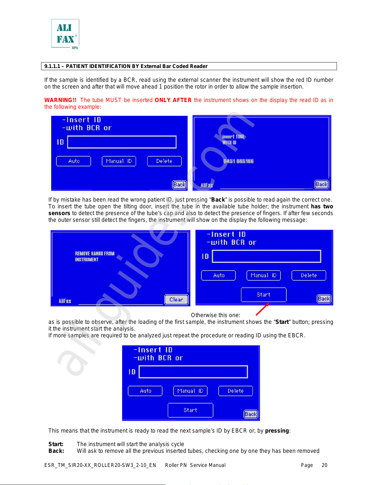
9.1.1.1 – PATIENT IDENTIFICATION BY External Bar Coded Reader
If the sample is identified by a BCR, read using the external scanner the instrument will show the red ID number
on the screen and after that will move ahead 1 position the rotor in order to allow the sample insertion.
WARNING!! The tube MUST be inserted ONLY AFTER the instrument shows on the display the read ID as in
the following example:
If by mistake has been read the wrong patient ID, just pressing “Back” is possible to read again the correct one.
To insert the tube open the tilting door, insert the tube in the available tube holder; the instrument has two
sensors to detect the presence of the tube’s cap and also to detect the presence of fingers. If after few seconds
the outer sensor still detect the fingers, the instrument will show on the display the fol lowing m essage:
Otherwise this one:
as is possible to observe, after the loading of the first sample, the instrument shows the “Start” button; pressing
it the instrument start the analysis.
If more samples are required to be analyzed just repeat the procedure or reading ID using the EBCR.
This means that the instrument is ready to read the next sample’s ID by EBCR or, by pressing:
Start: The instrument will start the analysis cycle
Back: Will ask to remove all the previous inserted tubes, checking one by one they has been removed
All manuals and user guides at all-guides.com
all-guides.com
Page 27
ESR_TM_SIR20-XX_ROLLER20-SW3_2-10_EN Roller PN Service Manual Page
21
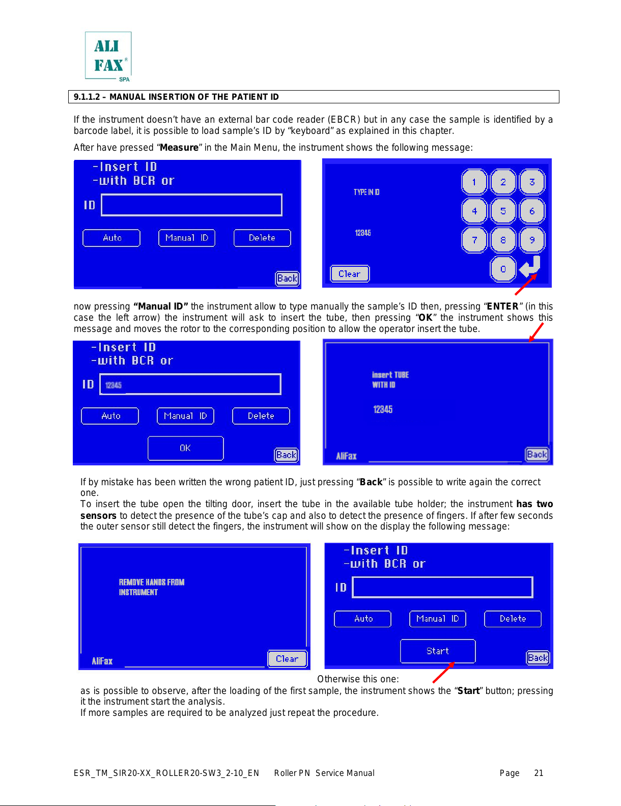
9.1.1.2 – MANUAL INSERTION OF THE PATIENT ID
If the instrument doesn’t have an external bar code reader (EBCR) but in any case the sample is identified by a
barcode label, it is possible to load sample’s ID by “keyboard” as explained in this chapter.
After have pressed “Measure” in the Main Menu, the instrument shows the following message:
now pressing “Manual ID” the instrument allow to type manually the sample’s ID then, pressing “ENTER” (in this
case the left arrow) the instrument will ask to insert the tube, then pressing “OK” the instrument shows this
message and moves the rotor to the corresponding position to allow the operator insert the tube.
If by mistake has been written the wrong patient ID, just pressing “Back” is possible to write again the correct
one.
To insert the tube open the tilting door, insert the tube in the available tube holder; the instrument has two
sensors to detect the presence of the tube’s cap and also to detect the presence of fingers. If after few seconds
the outer sensor still detect the fingers, the instrument will show on the display the following m essage:
Otherwise this one:
as is possible to observe, after the loading of the first sample, the instrument shows the “Start” button; pressing
it the instrument start the analysis.
If more samples are required to be analyzed just repeat the procedure.
All manuals and user guides at all-guides.com
Page 28
ESR_TM_SIR20-XX_ROLLER20-SW3_2-10_EN Roller PN Service Manual Page
22
This means that the instrument is ready to read the next sample’s ID by EBCR or, by pressing:
Start: The instrument will start the analysis cycle
Back: Will ask to remove all the previous inserted tubes, checking one by one they has been removed
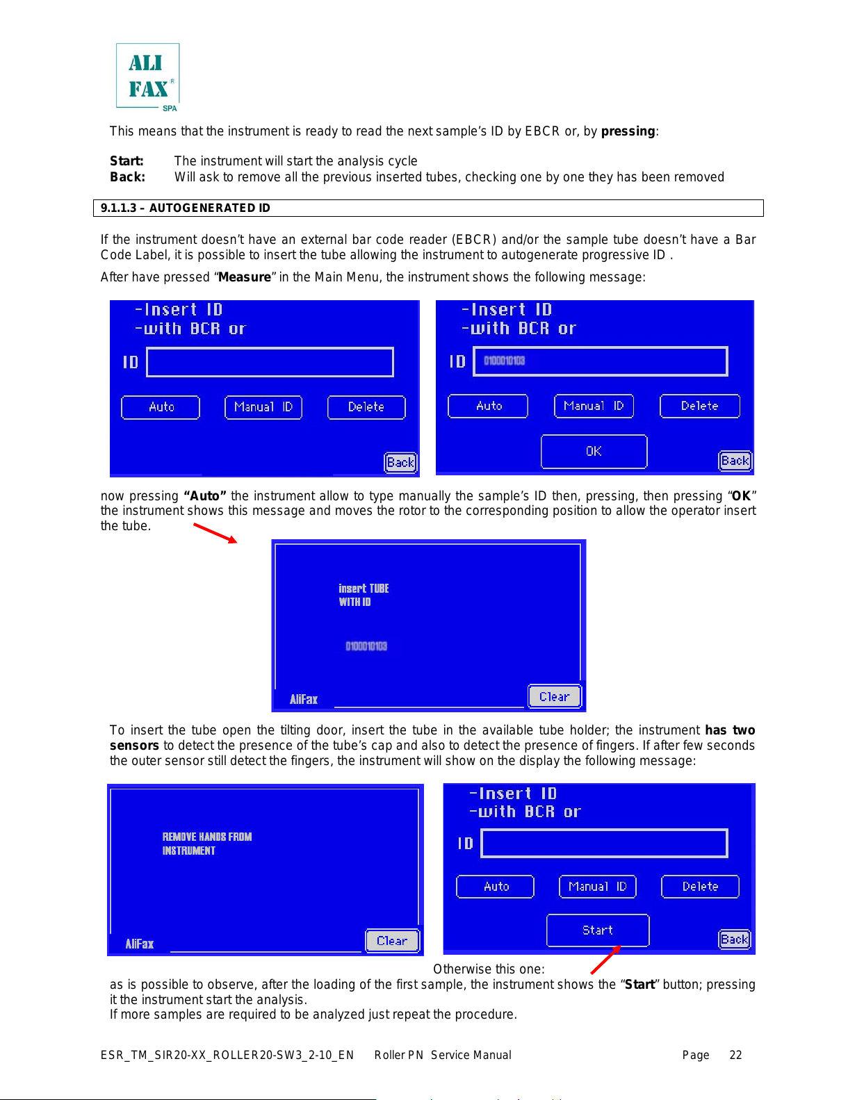
9.1.1.3 – AUTOGENERATED ID
If the instrument doesn’t have an external bar code reader (EBCR) and/or the sample tube doesn’t have a Bar
Code Label, it is possible to insert the tube allowing the instrument to autogenerate progressive ID .
After have pressed “Measure” in the Main Menu, the instrument shows the following message:
now pressing “Auto” the instrument allow to type manually the sample’s ID then, pressing, then pressing “OK”
the instrument shows this message and moves the rotor to the corresponding position to allow the operator insert
the tube.
To insert the tube open the tilting door, insert the tube in the available tube holder; the instrument has two
sensors to detect the presence of the tube’s cap and also to detect the presence of fingers. If after few seconds
the outer sensor still detect the fingers, the instrument will show on the display the fol lowi ng m essage:
Otherwise this one:
as is possible to observe, after the loading of the first sample, the instrument shows the “Start” button; pressing
it the instrument start the analysis.
If more samples are required to be analyzed just repeat the procedure.
All manuals and user guides at all-guides.com
Page 29
ESR_TM_SIR20-XX_ROLLER20-SW3_2-10_EN Roller PN Service Manual Page
23
This means that the instrument is ready to read the next sample’s ID by EBCR or, by pressing:
Start: The instrument will start the analysis cycle
Back: Will ask to remove all the previous inserted tubes, checking one by one they has been removed
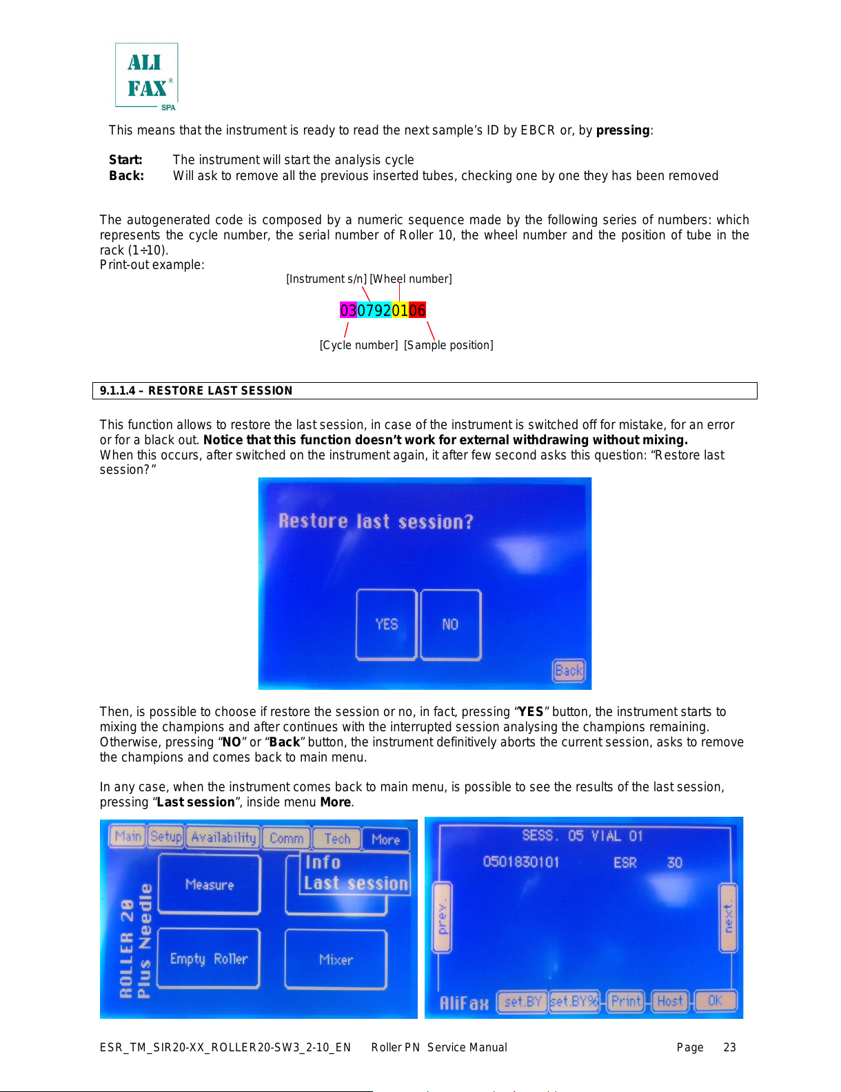
The autogenerated code is composed by a numeric sequence made by the following series of numbers: which
represents the cycle number, the serial number of Roller 10, the wheel number and the position of tube in the
rack (1÷10).
Print-out example:
[Instrument s/n] [Wheel number]
[Cycle number] [Sample position]
9.1.1.4 – RESTORE LAST SESSION
This function allows to restore the last session, in case of the instrument is switched off for mistake, for an error
or for a black out. Notice that this function doesn’t work for external withdrawing without mixing.
When this occurs, after switched on the instrument again, it after few second asks this question: “Restore last
session?”
Then, is possible to choose if restore the session or no, in fact, pressing “YES” button, the instrument starts to
mixing the champions and after continues with the interrupted session analysing the champions remaining.
Otherwise, pressing “NO” or “Back” button, the instrument definitively aborts the current session, asks to remove
the champions and comes back to main menu.
In any case, when the instrument comes back to main menu, is possible to see the results of the last session,
pressing “Last session”, inside menu More.
0307920106
All manuals and user guides at all-guides.com
Page 30
ESR_TM_SIR20-XX_ROLLER20-SW3_2-10_EN Roller PN Service Manual Page
24
9.1.1.5 – EXTERNAL SAMPLING PROCEDURE, USING INTERNAL MIXING
When using the external withdrawal procedure, it is mandatory to use gloves and all the others protective tools,
precautions and warnings necessary apt to avoid the contact in accordance with national laws.
In case the option chosen is external sampling normal or pediatric (with internal mixing), the instrument will ask
to load the samples and will mix them; then (after the mixing cycles have been executed) the instrument will
require to remove the samples from the rotor.
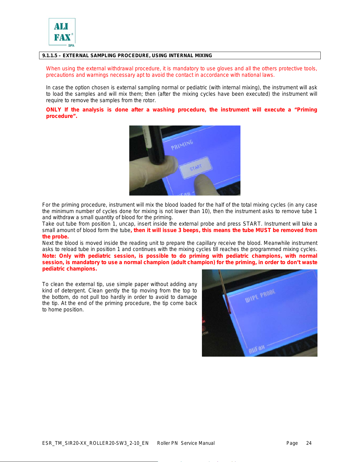
ONLY If the analysis is done after a washing procedure, the instrument will execute a “Priming
procedure”.
For the priming procedure, instrument will mix the blood loaded for the half of the total mixing cycles (in any case
the minimum number of cycles done for mixing is not lower than 10), then the instrument asks to remove tube 1
and withdraw a small quantity of blood for the priming.
Take out tube from position 1, uncap, insert inside the external probe and press START. Instrument will take a
small amount of blood form the tube, then it will issue 3 beeps, this means the tube MUST be removed from
the probe.
Next the blood is moved inside the reading unit to prepare the capillary receive the blood. Meanwhile instrument
asks to reload tube in position 1 and continues with the mixing cycles till reaches the programmed mixing cycles.
Note: Only with pediatric session, is possible to do priming with pediatric champions, with normal
session, is mandatory to use a normal champion (adult champion) for the priming, in order to don’t waste
pediatric champions.
To clean the external tip, use simple paper without adding any
kind of detergent. Clean gently the tip moving from the top to
the bottom, do not pull too hardly in order to avoid to damage
the tip. At the end of the priming procedure, the tip come back
to home position.
All manuals and user guides at all-guides.com
Page 31

ESR_TM_SIR20-XX_ROLLER20-SW3_2-10_EN Roller PN Service Manual Page
25
After the instrument has finished the mixing, will ask to remove from rotor the tube, then the probe will be moved
out and (after having uncapped) insert the tube over the probe all the way down. Next just press STA RT.
Note; when the aspiration is finished,
instrument will beep 3 times, this means the
tube must be removed from the external tip
and recapped.
The tube can be reloaded on the rotor or left outside the instrument (external rack) for other eventual analysis.
During the analysis, the instrument will ask to clean the
external tip. To clean the external tip, use simple paper
without adding any kind of detergent. Clean gently the tip
moving from the top to the bottom, do not pull too hardly in
order to avoid to damage the tip.
Then the instrument will move the rotor to the next
position and will ask to pick the next sample to be
analyzed.
During the session the instrument will display on the
screen the results obtained. Based on the printer setup,
the printer will printout the results in “real time” (that
means after each single analysis) or globally at the end
of the analysis cycle.
IMPORTANT:
In case of use of the external withdrawing tip, it is mandatory to clean it following the washing
procedure in order to avoid blood dries inside the tip causing the formation ob. blood clogs inside it.
The tip must be washed within 10 minutes before last sample analysis.
All manuals and user guides at all-guides.com
all-guides.com
Page 32

ESR_TM_SIR20-XX_ROLLER20-SW3_2-10_EN Roller PN Service Manual Page
26
9.1.1.6 – EXTERNAL SAMPLING WITHOUT INTERNAL MIXING
When using the external withdrawal procedure, it is mandatory to use gloves and all the others protective tools,
precautions and warnings necessary apt to avoid the contact in accordance with national laws.
In case the option chosen is external sampling WITHOUT MIXING,
Then, ONLY If the analysis is done after a w ashing procedure, the instrument will execute a “Priming
procedure”.
For the priming procedure, take a tube, uncap, insert inside the external probe and press START. Instrument will
take a small amount of blood form the tube, then it will issue 3 beeps, this means the tube MUST be removed
from the probe.
Next the blood is moved inside the reading unit to prepare the capillary receive the blood. Meanwhile instrument
asks to reload tube in position 1 and continues with the mixing cycles till reaches the programmed mixing cycles.
Note: in case of pediatric samples that normally contain few blood, in order not to waste them, the
withdrawal for the priming can be done using a previous analyzed sample or blood belonging to an adult)
To clean the external tip, use simple paper without adding
any kind of detergent. Clean gently the tip moving from the
top to the bottom, do not pull too hardly in order to avoid to
damage the tip.
All manuals and user guides at all-guides.com
Page 33

ESR_TM_SIR20-XX_ROLLER20-SW3_2-10_EN Roller PN Service Manual Page
27
After the priming, instrument asks to identify the sample to be analyzed; as f or the previous cases, the option are:
• Autogenerated ID
• Manual ID (typed manually)
• EBCR
Once pressed OK instrument asks to sample the tube just identified previously; after pressing START the
instrument will aspire the blood. In case of mistake, pressing the “BACK” button (not visible in the photo here
displayed) instrument returns to previous screen were user can re-insert the ID.
Note; when the aspiration is finished,
instrument will beep 3 times, this means the
tube must be removed from the external tip
and recapped.
During the analysis, the instrument will ask to clean the
external tip. To clean the external tip, use simple paper
without adding any kind of detergent. Clean gently the tip
moving from the top to the bottom, do not pull too hardly in
order to avoid to damage the tip.
At the end of the analysis, instrument show on the
screen the result (and also print it if the flag “print in
run” is enable), than after press OK button, reappears
the ID insertion screen and so you can choose if
analyse another sample, or pressing BACK button, to
end the session.
IMPORTANT:
All manuals and user guides at all-guides.com
Page 34

ESR_TM_SIR20-XX_ROLLER20-SW3_2-10_EN Roller PN Service Manual Page
28
In case of use of the external withdrawing tip, it is mandatory to clean it following the washing
procedure in order to avoid blood dries inside the tip causing the formation ob. blood clogs inside it.
The tip must be washed within 10 minutes before last sample analysis.
9.1.1.7 – ANALYSIS RESULTS (Display and Printouts)
After the sample analysis (independently of the internal or external withdrawal) the instrument will show on
display results and also printout each sample analysis’s result.
During the analysis the instrument will display on the screen the result obtained. Based on the printer setup, the
printer will printout the results in “real time” (that means after each single analysis) or globally at the end of the
analysis cycle.
The printout result looks like the one showed here:
For each session is reported:
Date and time of analysis
Session number (01 = first session of day)
Then for each sample is printed its position inside the rotor, patient’s ID and
the ESR results expressed in (mm/h)
, in this case all 6 parameter’s result are displayed, if (as explained in chapter 7 Increase Availability Test Using
Smart Card) one or more specific parameters are not available, the instrument will printout only the results for
the available parameters.
Attention, if the waste tank is full (the control is executed automatically by the instrument
before beginning a new session), is necessary to empty the waste tank before starting a new
session; otherwise, the instrument remains in standby until when the waste tank is emptied.
All manuals and user guides at all-guides.com
Page 35

ESR_TM_SIR20-XX_ROLLER20-SW3_2-10_EN Roller PN Service Manual Page
29
9.1.1.8 – ANALYSIS RESULTS DURING SECOND TAKE OF SAMPLE AND SAMPLE MISSING
This function allows, in case of the champion value is not detectable [NF (-4) / NR (-2)], to try a second taking.
With external withdrawing (normal, pediatric or without mixing) the instrument asks to fol l owing a specifi c
procedure.
When the value of one sample is not detectable, the instrument shows this screen:
Then, is possible to choose if analyse again the sample or no, in fact, pressing “YES” button, the instrument asks
to analyse again the sample and after pressing “START” button, is executed again the analysis procedure.
Otherwise, pressing “NO” or “Back” button, the instrument doesn’t analyse again the sample and then shows,
prints and sends to host (if is present) the value NF (-4) or NR (-2).
With internal withdrawing (normal or pediatric) the instrument does this operation automatically, m oving the
motors and analyzing the sample again. Also with this kind of withdrawing, if the second attempt fails, the
instrument shows, prints and sends to host (if is present) the value NF (-4) or NR (-2).
Moreover only with this kind of withdrawing, if a sample falls out from the rotor, the instrument notices it, in fact,
after 2 attempts the instrument shows, prints and sends to host (if is present) the value S. M . (-1).
NOTE: Every failed attempt, is saved inside the Error Log (see chapter 9.2.7.12) in this way:
1
ST
NF (INT or EXT) = failed first take (internal or external), not detected continuous blood flow;
2
ND
NF (INT or EXT) = failed second take (internal or external), not detected continuous blood flow;
1
ST
NR (INT or EXT) = failed first take (internal or external), sample not detectable;
2
ND
NR (INT or EXT) = failed second take (internal or external), sample not detectable;
WARN. SM = failed first take (only internal), sample missing;
SM = failed second take (only internal), sample missing;
NOTE: After 3 consecutive Samples Missing during the analysis (S.M.) the instrument generate the SM01 error
like in photo:
If this happen, please perform Roller technical assistance. However is possible press “OK” to continue.
All manuals and user guides at all-guides.com
Page 36

ESR_TM_SIR20-XX_ROLLER20-SW3_2-10_EN Roller PN Service Manual Page
30
9.1.2 – WASH MENU
Wash:
Pressing “Wash” (from Main Menu or from Main Screen) the instrument will set itself to be ready to perform a
wash cycle, will check the rotor status (requiring to remove eventually present tubes)
At this point, instrument requires to select the kind of wash desired:
This option is available
ONLY in Roller 20PN
configuration (chapter
9.1.2.3)
Now the operator need to choose the kind of wash and the instrument will activate the corresponding
procedures:
9.1.2.1 – INTERNAL WASH
In this configuration, the instrument requires to load 2 tests-tube filled 3/4 with distil led wat er and then active the
washing procedure.
At the end of the washing cycle, the instrument will printout a report in which it shows the parameters of the
photometer and it will also show them on display (this only with “Debug on”), like in the following example.
All manuals and user guides at all-guides.com
all-guides.com
Page 37

ESR_TM_SIR20-XX_ROLLER20-SW3_2-10_EN Roller PN Service Manual Page
31
If for any reason the washing procedure reports “PHOTOMETER NOT OK” means that the washing cycle has
not been executed correctly.
Now pressing “OK”; the instrument will display the following message that suggest to repeat the washing
procedure.
Attention, if the waste tank is full (the control is executed automatically by the instrument
before beginning a new session), is necessary to empty the waste tank before starting a new
session; otherwise, the instrument remains in standby until when the waste tank is emptied.
9.1.2.2 – AUTOMATIC WASH
In this configuration, the instrument executes the washing using the water available in the washing tank located
inside the instrument; it is not required to load washing test-tubes.
At the end of the washing cycle, the instrument will printout a report in which it shows the parameters of the
photometer and it will also show them on display (this only with “Debug on”), like in the following exampl e.
If for any reason the washing procedure reports “PHOTOMETER NOT OK” means that the washing cycle has
not been executed correctly.
Now pressing “OK”; the instrument will display the following message that suggest to repeat the washing
procedure.
All manuals and user guides at all-guides.com
Page 38

ESR_TM_SIR20-XX_ROLLER20-SW3_2-10_EN Roller PN Service Manual Page
32
Attention, if the waste tank is full (the control is executed automatically by the instrument
before beginning a new session), is necessary to empty the waste tank before starting a new
session; otherwise, the instrument remains in standby until when the waste tank is emptied.
9.1.2.3 – EXTERNAL WASH
Using this option, the instrument executes the wash of the hydraulic circuit connected to the manual withdrawal
needle.
In this case the instrument doesn’t require to load washing tubes because the washing is executed manually; the
instrument moves down the external tip to the withdrawing position, from where it will aspire water from the
washing tube.
Then after inserting the washing tube over the needle, pressing Start the washing procedures is activated.
At the end of the washing cycle, the instrument will printout a report in which it shows the parameters of the
photometer and it will also show them on display (this only with “Debug on”), like in the foll owing example.
If for any reason the washing procedure reports “PHOTOMETER NOT OK” means that the washing cycle has
not been executed correctly.
Now pressing “OK”; the instrument will display the following message that suggest to repeat the washing
procedure.
All manuals and user guides at all-guides.com
Page 39

ESR_TM_SIR20-XX_ROLLER20-SW3_2-10_EN Roller PN Service Manual Page
33
Attention, if the waste tank is full (the control is executed automatically by the instrument
before beginning a new session), is necessary to empty the waste tank before starting a new
session; otherwise, the instrument remains in standby until when the waste tank is emptied.
9.1.2.4 –WASHINGS PROCEDURE DESCRIPTION
This procedure is designed to guarantee the capillary and all the hydraulic circuitries are maintained clean and
free of blood residuals.
Considering the instrument uses a Teflon tube in which blood, water and latex flows, it is normal that the internal
walls of the capillary tend to become opaque, and also to remain dirty because some blood residual parts remain
inside the capillary.
To ensure a long lasting capillary, the instrument allows to use four different washing options (according to the
use of the instrument: with or without use of latex).
In any case it is important to remember that the use of latex overcomes all the problems related to the use of
haematic samples as control standards.
Washing options:
• Washing using 2 test tubes
• Washing using 3 test tubes (optionally third tube filled with a detergent liquid like those used in CBC)
• Maintenance washing
• Washing if latex controls are used.
At the end of every washing procedure the software, with the attempt to reach the original value (called white
value) which is 3800, updates an internal compensator factor value according to the read water value (e.g. Wt.
3796).
To every incorrect washing procedure, (water value >4095, <2000 water mixed with bubbles, anomalous
water flow, etc.) the instrument will generate a PHOTOMETER NOT OK error and a new washing procedure
will be requested.
WASHING USING 2 TEST TUBES
This option is used when the instrument requires or needs to be washed in a "normal" way. After this has
ended the instrument is ready to continue working.
This procedure requires to load 2 test tubes filled 3/4 with distilled water; tubes are loaded in position 1 and 2 of
the rotor.
To activate the procedure select Wash from the MAIN MENU, and the choose “Internal” and load the tubes and
wait until the "MAIN MENU (0)" is displayed enabling further choices.
For PN Models, if necessary to wash the external windrowing circuit (manual windrowing), choose the
“External” option, in this case, will be washed out the external windrowing circuit.
This option is available
ONLY in Roller 20PN
configuration (chapter
9.1.2.3)
All manuals and user guides at all-guides.com
Page 40

ESR_TM_SIR20-XX_ROLLER20-SW3_2-10_EN Roller PN Service Manual Page
34
At the end of the washing
procedure, the instrument
will be ready to continue
with the analytical sessions.
WASHING USING 3 TEST-TUBES (optionally third tube filled with a detergent liquid)
This option is used at the end of the working day and offers the possibility to maintain the capillary moist
overnight. This is useful because all the hydraulic circuitry remains filled with water or with detergent (CBC
detergent).
The advantage of this procedure is that all residual blood particles that eventually have remained inside the
capillary, are kept moist avoiding them to remain stuck over the internal capillary walls.
This procedure requires 3 test tubes that will be loaded in two consecutive steps.
First step is the same described in the previous chapter “washing using 2 test-tubes”.
In the second step, independently from the typology of chosen wash (Internal, Automatic or External), the
instrument prints out the result of washing procedure, then requires to remove the two tests-tube, only if the
instrument is Roller 10 or Roller 10PN, while for the Roller 20 PN requires it ONLY if the “Internal” washing has
been chosen. After have removed the tests-tube from positions 1 and 2, the instrument, independently from its
configuration, requires the insertion of an ulterior test-tube always with distilled water (or cbc liquid detergent) in
position 1. From this test-tube it will windrow approximately 1/3 of the content, then the instrument will stop the
pump leaving the needle inside the test-tube and it will ask to switch OFF the instrument.
This system maintains all the hydraulic circuit filled with water (or cbc detergent) and avoids that eventual residual
particles of blood dries and stick to the inner wall of the capillary.
At the next switch ON the instrument will empty the residual water from the capillary and will ask the removal for
the test-tube
If the third test-tube had been filled up with liquid detergent, an ulterior washing must be executed using 2
tests-tube filled up for ¾ with 'distilled water; this washing is used to remove completely all the residual liquid
detergent before beginning a new analytical session.
The procedure of washing with 3 tests-tube IT MUST BE DONE at the end of the working day in order to
guarantee a good and efficient maintenance of the instrument
WASHING PROCEDURE FOR MAINTENANCE
This option MUST be used if the instrument works without latex controls.
For a good maintenance of the instrument it is required to use Sodium Hypochlorite (diluted at 5%) on a specific
basis according to the quantity of samples analyzed daily:
20 or less samples a day: every 2 weeks
40 or less samples a day: every week
60 or more samples a day: twice a week
Execute one first washing, selecting “Wash”, then option “Internal”, load 2 test-tube filled ¾ with
distilled water in positions 1 and 2 of the rotor.
All manuals and user guides at all-guides.com
Page 41

ESR_TM_SIR20-XX_ROLLER20-SW3_2-10_EN Roller PN Service Manual Page
35
This option is available
ONLY in Roller 20PN
configuration (chapter
9.1.2.3)
Execute a second washing selecting “Wash” then option “Internal ” and to load in position a 1 test-tube
filled up ¾ with sodium hypochlorite (diluted at 5%), while in position 2, a test-tube filled up ¾ with
distilled water.
Execute one third session of washing selecting “Wash”, then option “Internal”, load 2 test-tube filled ¾
with distilled water in positions 1 and 2 of the rotor.
The procedure can be carried out also of capillary and/or needle in the event obstructed
9.1.2.5 WASHING PROCEDURE IN CASE OF USE OF LATE X CONTROLS
If the instrument is controlled using Latex Control Kit, this procedure MUST be done every time
latex controls are used.
At the beginning of each Latex Controls session:
Execute one first washing, selecting “Wash”, then option “Internal”, load 2 test-tube filled ¾ with
distilled water in positions 1 and 2 of the rotor
Execute a second washing selecting “Wash” then option “Internal ” and to load in position a 1
test-tube filled up ¾ with sodium hypochlorite (diluted at 5%), while in position 2, a test-tube filled
up ¾ with distilled water.
Now is possible to execute the Latex Control session. Choose the option “Standard” located inside
“Main” menu. Load in position a 1 test-tube filled up ¾ with distilled water, then the three latex-
tubes and the others two tests-tube filled up for ¾ with distilled water following the instructions
indicated on the screen.
At the end of the working day:
Prepare 3 tests-tube filled up ¾ with distilled water (eventually the third test-tube can contain a
liquid detergent).
Select the option “Wash and Sleep” located inside “Main” menu, then option “Internal” ( if the
external withdrawing tip has been used, select “External” ), and follow the instructions shown on
the screen.
After have removed tests-tube from positions 1 and 2, the instrument, independently from its
configuration (Roller 10, Roller 10PN or Roller 20PN), requires to load the third test-tube always
with distilled water (or liquid detergent) in position 1. From this test-tube it will be windrowed
approximately 1/3 of the content, then the instrument will stop the pump leaving the needle inside
the test-tube and it will ask to switch OFF.
All manuals and user guides at all-guides.com
all-guides.com
Page 42

ESR_TM_SIR20-XX_ROLLER20-SW3_2-10_EN Roller PN Service Manual Page
36
9.1.2.6 – END OF WORKING DAY WASHING PROCEDURE (Wash and Sleep)
This option is used at the end of the working day and offers the possibility to maintain the capillary moist
overnight. This is useful because all the hydraulic circuitry remains filled with water or with detergent (CBC
detergent).
The advantage of this procedure is that all residual blood particles that eventually have remained inside the
capillary, are kept moist avoiding them to remain stuck over the internal capillary walls.
Wash and Sleep:
To activate the procedure select “Wash and Sleep” from the MAIN MENU,the instrument asks to select the
tipology of desired washing:
This option is available ONLY in Roller 20PN configuration (chapter 9.1.2.3)
Selecting the “Internal”, the instrument requires the insertion of two tests-tube(in position 1 and 2 of the rotor)
filled up 3/4 with distilled water and then active the washing procedure.
At the end of the washing cycle, the instrument will printout a report in which it shows the parameters of the
photometer and it will also show them on display (this only with “Debug on”), like in the foll owing example.
If for any reason the washing procedure reports “PHOTOMETER NOT OK” means that the washing cycle has
not been executed correctly.
All manuals and user guides at all-guides.com
Page 43

ESR_TM_SIR20-XX_ROLLER20-SW3_2-10_EN Roller PN Service Manual Page
37
Now pressing “OK”; the instrument will display the following message that suggest to repeat the washing
procedure.
In the second step, independently from the typology of chosen wash (Internal, Automatic or External), the
instrument after have printed out the result of washing procedure, will requires to remove both tests-tube, only if
the instrument is Roller 10 or Roller 10PN, while for the Roller 20 PN will require it ONLY if the “Internal” washing
has been chosen. After have removed the tests-tube from positions 1 and 2, the instrument, independently from
its configuration, requires the insertion of an ulterior test-tube always with distilled water (or cbc liquid detergent)
in position 1. From this test-tube it will windrow approximately 1/3 of the content, then the instrument will stop
the pump leaving the needle inside the test-tube and it will ask to switch OFF the instrument.
This system maintains all the hydraulic circuit filled with water (or cbc detergent) and avoids that eventual
residual particles of blood dries and stick to the inner wall of the capillary.
At the next switch ON the instrument will empty the residual water from the capillary and will ask to remove the
test-tube.
If the third test-tube had been filled up with liquid detergent, an ulterior washing must be executed using 2
tests-tube filled up ¾ with distilled water; this washing is used to remove completely all the residual detergent
liquid before beginning a new analytical session.
The procedure of washing with 3 tests-tube MUST BE EXECUTED at the end of each working day in order to
guarantee a good and efficient maintenance of the instrument.
Attention, if the waste tank is full (the control is executed automatically by the instrument
before beginning a new session), is necessary to empty the waste tank before starting a new
session; otherwise, the instrument remains in standby until when the waste tank is emptied.
9.1.2.7 – WASHING ERRORS
If for any reason the washing procedure reports “PHOTOMETER NOT OK” means that the washing cycle has
not been executed correctly or has been found anomalies in the system.
The possible causes of malfunctioning can be:
It has been inserted an empty WASH tube,
One or both tube are missing
Washing reference level lower than 2500
Washing reference level inside the range (2500 – 4000) but not detected sample’s end
Washing reference level higher than 4095
Detected air bubbles during the washing procedure
Washing tank empty
9.1.2.8 –WASHINGS PROCEDURE ERRORS (MEANING OF WASHING FLAGS IN DEBUG ON)
When configured in DEBUG ON the instrument, during washing procedures (even on latex) shows on the right
side of the screen
All manuals and user guides at all-guides.com
Page 44

ESR_TM_SIR20-XX_ROLLER20-SW3_2-10_EN Roller PN Service Manual Page
38
Four flags which at the beginning of the washing are all at zero; during the washing flags start to change to 1.
• 1° flag means capillary constantly empty
• 2° flag means it has been detected the front water arriving (this DOESN’T MEANS DETECTION OF
CONSTANT FLOW), in other word a simple drop of water will change the flag from 0 to 1
• 4° flag means detection of constant flow during 5 seconds for a normal was and 8 second for washing
before latex readings (first water tube before control/calibrators)
• 3° flag means detection of capillary empty after a correct detection of water flow, this happens after 4th
flag change from 0 to 1
Referring the table here after, photometer recognizes ADC values as:
• >= 2500 points, means capillary full
• < 2500 points means capillary empty
Possibile situations:
Flags
Meaning
Cause
0000
Capillary not empty
Not done First-Up (only on new capillaries or when CPS is
new in that case DAC is set at 1023 thus photometer sees
ADC >2500
and consequently it is not able to detect the
initial emptiness of capillary)
1000
Capillary empty but no water flow
detected
- Empty tube
- Led o photometer damaged (photometer detect always 0
and understand as capillary empty)
- Washing Tank empty (R20PN on automatic wash
sequence)
1100
Capillary empty, detected water flow
but not enough constancy of flow
(5/8 seconds)
- Capillary or needle obstructed
- Few water inside washing tubes
- Air bubbles aspired due to old stopper or weared out
stopper (internal washing)
- Air bubbles aspired due to damaged capillary (leakage
between funnel and needle or capillary pierced)
- Air bubbles aspired due needle not well fixed not fully
screwed in or needle loosed (internal and automatic
washing)
- Air bubbles aspired due external probe not well fixed not
fully screwed in or needle loosed (external washing)
- Washing Tank empty (R20PN on automatic wash
sequence)
- Air bubbles stuck inside capillary surface, run a wash
with beach top remove them
- DAC set at maximum value during calibration washing
(>1013 points)
1101
Capillary empty, detected constancy
of water flow for 5/8 seconds but
capillary still not empty
- Capillary or needle obstructed
- Error during emitter calibration procedure, air bubble in
front the photometer (extremely rare because since Sw
2.00C a specific control routine has been issued)
- Waste tank full which doesn’t allow waste flow to be
discharged inside the tank (extremely rare due to sw
control routines)
1111
Washing OK (capillary empty)
Eventually 3rd flag could remain 0 is a drop of water is
still in front the sensor even with capillary conceptually
empty
All manuals and user guides at all-guides.com
Page 45

ESR_TM_SIR20-XX_ROLLER20-SW3_2-10_EN Roller PN Service Manual Page
39
All manuals and user guides at all-guides.com
Page 46

ESR_TM_SIR20-XX_ROLLER20-SW3_2-10_EN Roller PN Service Manual Page
40
9.1.3 – STANDARD (Latex control / calibration)
PRINCIPLE OF METHOD
The Control kit is based on the use of three samples with known turbidity values, on which the analyzer
performs transmittance measurements related to ESR values. The results obtained should fit the expected
ranges. Otherwise the calibration of the instrument shall be verified.
Please refer to chapter 9.1.6 for quality control and statistical tools.
At the beginning of each Latex Controls session:
Execute one first washing, selecting “Wash”, then load 2 test-tube filled ¾ with distilled water in
positions 1 and 2 of the rotor (or in case of external circuit, wash it using 1 tube)
Execute a second washing selecting “Wash” then option “Internal ” and to load in position a 1
test-tube filled up ¾ with sodium hypochlorite (diluted at 5%), while in position 2, a test-tube filled
up ¾ with distilled water.
Now is possible to execute the Latex Control session. Choose the option “Standard” located inside
“Main” menu. Load in position a 1 test-tube filled up ¾ with distilled water, then the three latex-
tubes and the others two tests-tube filled up for ¾ with distilled water following the instructions
indicated on the screen.
At the end of the working day:
Prepare 3 tests-tube filled up ¾ with distilled water (eventually the third test-tube can contain a
liquid detergent).
Select the option “Wash and Sleep” located inside “Main” menu, then option “Internal” ( if the
external withdrawing tip has been used, select “External” ), and follow the instructions shown on
the screen.
After have removed tests-tube from positions 1 and 2, the instrument, independently from its
configuration (Roller 10, Roller 10PN or Roller 20PN), requires to load the third test-tube always
with distilled water (or liquid detergent) in position 1. From this test-tube it will be windrowed
approximately 1/3 of the content, then the instrument will stop the pump leaving the needle inside
the test-tube and it will ask to switch OFF.
Considering the instrument mounts two independent reading units (CPS), after having pressed “Standard”
(from Main Menu) the instrument will first ask to select which circuit will be interested by the latex procedure.
After the selection the procedure is exactly the same for both circuits, the main difference is in the internal
circuit instrument does everything automatically after water and latex loading on the rotor. If the external
circuit is choosen, the instrument also asks to load the water and latex tubes (like for internal circuit) but then
after mixing it will ask to remove one by one the tubes and perform every step by hand.
If latex Calibrators are loaded, instrument w ill require to login as Technical User otherwise it w ill not
allow to continue with the calibration process.
All manuals and user guides at all-guides.com
all-guides.com
Page 47

ESR_TM_SIR20-XX_ROLLER20-SW3_2-10_EN Roller PN Service Manual Page
41
After the selection Internal / External instrument asks to insert tubes following a sequence:
• 1 tube filled ¾ with distilled water
• 1 tube “tube 2” , “tube 3” and “tube 4” of Latex control previous identification by EBCR or typing manually the
number printed below the bar code
as it is possible to see, latex ID can be inserted by means of:
• External Bar Code Reader (just read the label and insert the tube)
• Typing manually (after having selected “Manual”) and pressing the arrow, then press ok and insert the tube
• Recalling an already memorized triplet (after having selected “Memo”), press OK button and insert the tube
IMPORTANT: AFTER THE SAME TRIPLET’S CODES HAVE BEEN USED 6 TIMES, IN THE EVENT OF A 7
th
EXTERNAL
LOADING PROCEDURE, INSTRUMENT WILL AUTOMATICALLY DISCARD THE TUBE’S CONTENT TO WASTE TANK
USING THE INTERNAL NEEDLE
• And the 2 more t ubes filled ¾ with distillated water
The instrument will check:
• If the Latex expiration date has been passed, in this case it will withdraw the content of the 3 latex tubes
without performing the control or calibration
• if the three tubes belongs to the same kit, if not will tell the inserted codes are inconsistent, in that case
press “Exit” and the instrument will ask to remove the tubes.
• if more than 6 weeks has passed after the first piercing date of the inserted triplet, in this case it will
withdraw the content of the 3 latex tubes without performing the control or calibration
All manuals and user guides at all-guides.com
Page 48

ESR_TM_SIR20-XX_ROLLER20-SW3_2-10_EN Roller PN Service Manual Page
42
• if the loaded triplet has been used more than 6 times, in this case it will withdraw the content of the 3
latex tubes without performing the control or calibration
If all checks are ok, it will begin the control procedure.
After the mixing, if the internal circuit is chosen instrument does the procedure automatically, if external
circuit is chosen, instrument will ask to remove one after the other the tubes in sequence.
Probe will be moved down and instrument will aspire water and the latex guiding the User step by step.
Sequence
1) Take out the first tube (water) and close the door, after that tube is inserted over the probe and user press
START
2) Instrument asks to wipe the probe, then to take out the first latex tube, close the door, after that tube is
inserted over the probe and user press START, instrument will perform a PRIMING procedure aspiring a
small quantity of latex and then will issue 3 beeps, this means the tube MUST BE REMOVED FORM THE
PROBE, and the probe wiped out meanwhile the instrument does the priming.
3) After priming instrument asks to wipe the probe, and then to reinsert tube 2 on the probe and pressing
START instrument initiate the latex control/calibration aspiring the aliquot of latex, then will issue 3 beeps,
this means the tube MUST BE REMOVED FORM THE PROBE and the probe wiped out
The same procedure will be repeated for tube 3 and 4 of latex
All manuals and user guides at all-guides.com
Page 49

ESR_TM_SIR20-XX_ROLLER20-SW3_2-10_EN Roller PN Service Manual Page
43
4) After latex, take out tube 5 (water) to run first washing after latex, followed by a second wash after latex
(tube 6).
5) Finished the washing procedures, instrument will display the expected values and the obtained values
Printout displayed in next page shows a printed report after a Latex Control, as is possible see it is divided in 4
main parts:
All manuals and user guides at all-guides.com
Page 50

ESR_TM_SIR20-XX_ROLLER20-SW3_2-10_EN Roller PN Service Manual Page
44
Latex Control Printout:
Part 1:
Barcodes of latex inserted:
Latex 2: first code of latex read
Latex 3: second code of latex read
Latex 4: third code of latex read
Part 2:
Latex lot number and progressive number of the lot.
Values of the DAC before and after washing
Part 3:
Washing sequence, here instrument print out the water values of the three
tubes (1
st
before latex and then last 2 after latex)
Also report if Photometer is OK or NOT OK
Part 4:
Operative parameters set to the Reading Unit:
Type of reference (EDTA or Citrate )
BoosterY (EDTA or Citrate, in base to the reference chosen)
MFact 1
MFact2
Temperature
Part 5:
In this part the instrument printout the result get after the Control procedure
Expected values
Measured values.
All manuals and user guides at all-guides.com
Page 51

ESR_TM_SIR20-XX_ROLLER20-SW3_2-10_EN Roller PN Service Manual Page
45
9.1.3.a – BoosterY adjustment when comparing against Westergreen Method
The BoosterY enables the adjustment and eventual correction of Roller results when compared to those
obtained with WESTERGREN in EDTA reference method.
The procedure for calibration is :
1. Use fresh blood samples (less than 3 hours from withdrawal) with an hematocrit level higher than 0.37.
2. Evaluate with ROLLER instrument the ESR values, then select at least 30 samples with ESR values in
the range 20÷80 mm/H.
3. On these samples evaluate the ESR WESTERGREN in EDTA and compare the results with those
obtained with the TEST1.
If systematic divergence is observed between methods, it is necessary to adjust the BoosterY.
How to calculate the new BoosterY:
1. Use the ESR value to obtain its relative integral (associated integral) as listed in table below.
2. Calculate the ratio between the integral of WESTERGREN ESR and the integral of ROLLER instrument
ESR.
3. Calculate the MEAN RATIO of all values of ratios obtained in 2.
4. Multiply this MEAN RATIO by the GAIN recorded into ROLLER instrument. The result will be the new
GAIN value giving the best fit of ROLLER instrument results to WESTERGREN 1H in EDTA.
TABLE OF ESR VALUES ASSOCIATED TO RELATIVE INTEGRAL
ESR
associated
integral
ESR
associated
integral
ESR
associated
integral
ESR
associated
integral
ESR
associated
integral
0
3.4
25
8.5
50
10.9
84
13.3
124
15.7 1 4.1
26
8.6
51
11.0
85
13.4
126
15.8 2 4.6
27
8.7
53
11.1
87
13.5
128
15.9 3 4.9
28
8.8
54
11.2
88
13.6
130
16.0 4 5.2
29
8.9
55
11.3
90
13.7
132
16.1 5 5.5
30
9.0
57
11.4
91
13.8
134
16.2 6 5.7
31
9.1
58
11.5
93
13.9
136
16.3 7 5.9
32
9.2
59
11.6
95
14.0
138
16.4 8 6.1
33
9.3
60
11.7
96
14.1
140
16.5 9 6.3
34
9.4
62
11.8
98
14.2
142
16.6
10
6.5
35
9.5
63
11.9
100
14.3
144
16.7
11
6.6
36
9.6
65
12.0
101
14.4
146
16.8
12
6.8
37
9.7
66
12.1
103
14.5
148
16.9
13
6.9
38
9.8
67
12.2
105
14.6
150
17.0
14
7.1
39
9.9
69
12.3
107
14.7
152
17.1
15
7.2
40
10.0
70
12.4
108
14.8
154
17.2
16
7.3
41
10.1
72
12.5
110
14.9
156
17.3
17
7.5
42
10.2
73
12.6
112
15.0
158
17.4
18
7.6
43
10.3
74
12.7
114
15.1
160
17.5
19
7.8
44
10.4
76
12.8
115
15.2
163
17.6
20
7.9
45
10.5
77
12.9
117
15.3
165
17.7
21
8.0
46
10.5
79
13.0
119
15.4
167
17.8
22
8.1
47
10.6
80
13.1
120
15.5
169
17.9
23
8.3
48
10.7
81
13.1
121
15.5
170
18.0
24
8.4
49
10.8
82
13.2
122
15.6
171
19.0
All manuals and user guides at all-guides.com
all-guides.com
Page 52

ESR_TM_SIR20-XX_ROLLER20-SW3_2-10_EN Roller PN Service Manual Page
46
Example of Roller values underestimated respect to reference WESTERGREN 1H in EDTA:
Sample.
N.
ESR
Roller
associated
integral
ESR WG
associated
integral
Ratio
1
12
6.8
20
7.9
7.9/6.8 = 1.16
2
44
10.4
65
12.0
12.0/10.4 = 1.15
3
80
13.1
130
16.0
16.0/13.1 = 1.22
4 3 4.9 7 5.9
5.9/4.9 = 1.20
5
22
8.1
36
9.6
9.6/8.1 = 1.18
6
49
10.8
76
12.8
12.8/10.8 = 1.18
7
88
13.6
140
16.5
16.5/13.6 = 1.21
8
62
11.8
98
14.2
14.2/11.8 = 1.20
9
55
11.3
78
13.0
13.0/11.3 = 1.15
10
35
9.5
58
11.5
11.5/9.5 = 1.21
The calculated MEAN RATIO is 1.18:
(1.16+1.15+1.22+1.20+1.18+1.18+1.21+1.20+1.15+1.21)/10= 1.18 = Mean Rati o
Example of Roller values overestimated respect to reference WESTERGREN 1H in EDTA:
Samp. N.
ESR
Roller
associated
integral
ESR WG
associated
integral
Ratio
1
20
7.9
12
6.8
6.8/7.9 = 0.86
2
65
12.0
44
10.4
10.4/12.0 = 0.86
3
130
16.0
80
13.1
13.1/16.0 = 0.81
4 7 5.9 3 4.9
4.9/5.9 = 0.83
5
36
9.6
22
8.1
8.1/9.6 = 0.84
6
76
12.8
49
10.8
10.8/12.8 = 0.84
7
140
16.5
88
13.6
13.6/16.5 = 0.82
8
98
14.2
62
11.8
11.8/14.2 = 0.83
9
78
13.0
55
11.3
11.3/13.0 = 0.87
10
58
11.5
35
9.5
9.5/11.5 = 0.82
The calculated MEAN RATIO is 0.83:
(0.86+0.86+0.81+0.83+0.84+0.84+0.82+0.83+0.87+0.82)/10= 0.83 = Mean Ratio.
Example:
1.15 = previous recorded BoosterY
1.18 = MEAN RATIO
The new adjusted BoosterY is: 1.15x1.18 = 1.357
To change BoosterY’s value please refer to chapter 9.2.1.1.a
All manuals and user guides at all-guides.com
Page 53
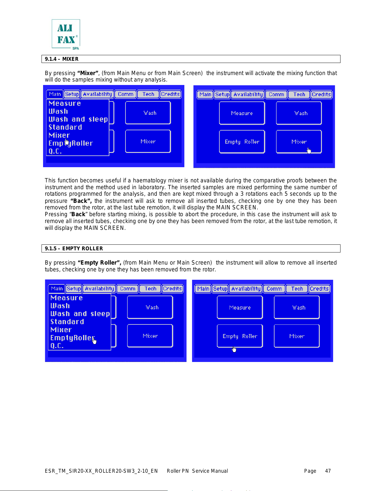
ESR_TM_SIR20-XX_ROLLER20-SW3_2-10_EN Roller PN Service Manual Page
47
9.1.4 – MIXER
By pressing “Mixer”, (from Main Menu or from Main Screen) the instrument will activate the mixing function that
will do the samples mixing without any analysis.
This function becomes useful if a haematology mixer is not available during the comparative proofs between the
instrument and the method used in laboratory. The inserted samples are mixed performing the same number of
rotations programmed for the analysis, and then are kept mixed through a 3 rotations each 5 seconds up to the
pressure “Back”, the instrument will ask to remove all inserted tubes, checking one by one they has been
removed from the rotor, at the last tube remotion, it will display the MAIN SCREEN.
Pressing “Back” before starting mixing, is possible to abort the procedure, in this case the instrument will ask to
remove all inserted tubes, checking one by one they has been removed from the rotor, at the last t ube rem otion, it
will display the MAIN SCREEN.
9.1.5 – EMPTY ROLLER
By pressing “Empty Roller”, (from Main Menu or Main Screen) the instrument will allow to remove all inserted
tubes, checking one by one they has been removed from the rotor.
All manuals and user guides at all-guides.com
Page 54

ESR_TM_SIR20-XX_ROLLER20-SW3_2-10_EN Roller PN Service Manual Page
48
9.1.6 – INTERNAL QUALITY CONTROL
ROLLER family analyser provides a series of control tools for an effective product performances monitoring; such
control tools are the following:
1. Photometrical check done during each washing.
2. Statistical daily control, that uses as reference population the same samples analyzed during the last 30
days, till a maximum of 6000 data. There are possible four different printouts, that report the control on all
the range of the results (from 2 to 120 mm/h) or only those relative to results considered normal (AON -
Average Of Normal - from 2 to 30 mm/h).The explanation of such controls is detailed in the chapter
"Presentations of statistical data".
3. The ESR determination is susceptible to several variables (temperature, performing, sample state,
results reading).
Since the phenomenon of erythrocyte sedimentation is confined to fresh blood and is transient, quality
control procedures are based on the comparison of the results with the reference method performed on
fresh samples. According to these remarks, the traditional control materials are not able to reproduce
correctly the phenomenon.
For laboratory quality control it is then important to have at disposal a control system reproducible and
easy to handle. This system is available using a Latex Control kit (
Ord. code SI 305.100-A/SI 305.102-A or
SI 305.300-A/ SI 305.302-A) that was designed expressly for TEST1 family (TEST1, MicroTEST1, Roller20)
and now also for ROLLER 10 family
(Roller 10, Roller 10 Plus Needle, Roller 20 Roller 20 Plus Needle). Refer
to chapter 9.1.3 for latex control procedures.
Pressing “Q.C.”, (from Main Menu) the instrument, in case of Roller instrument having two independent reading
units has also two independent statistical databases so before getting access to the statistics options it is
necessary select the circuit of interest:
After that, instrument displays the Statistical Main Menu:
The instrument collects data from:
• ESR statistical analysis classified by:
a) average, cumulative and daily distribution
on the “Global” range (ESR from 2 to
120)
b) average, cumulative and daily distribution on
the “Normal” range (ESR from 2 to 30)
• Latex Control results
• Washing procedures
All manuals and user guides at all-guides.com
Page 55

ESR_TM_SIR20-XX_ROLLER20-SW3_2-10_EN Roller PN Service Manual Page
49
9.1.6.1 – WASHING QUALITY CONTROL PRINTOUT - Graph meaning
This function allows to printout statistical data about the washings (independently they are Internal, External or
Automatic) executed on the instrument:
The printout of the washing c ontrol allows to estimate the efficiency of the photometer. The diagram visualizes
the trend of washing values detected by the three sensors, which are directly correlated to the photometric
signal. Normally, the instruments are regulated automatically around to an absolute value of 3800 during the
washing with distilled water. This value tends to move down during the time, because of the residues of biological
material inside the capillary.
Pressing “Print (5-1)” activates the printout that represents the behaviour and the tendency of the photometric
values correspondents to the values of the water.
How can see from the graph below, the instrument shows the trend of the last 30 days, from which is easy to
identify any possible drift or abnormal values.
Explanation and interpretation of the diagram:
References of the sensors: 1, 2 and stop
Lower and Upper limits of water acceptability, ideal reference is 3800.
This indication that identify the instrument has been switched
ON, not used and switched OFF
This indication identify that the instrument has been switched
ON, used and then switched OFF without have been washed or
every time Photometer NOK is issued
This indication means that the instrument has been washed and the
three sensors has detected a water value included within the lower and
higher limits:
sensor 1: 3757
sensor 2: 3770
stop sensor: 3829
On the graphical print out, the instrument prints always the last
washing executed in the day, independently from how many had been
effectively is executed. In case more washings had been done during
the same day, the data is overwritten. At midnight (change of the day),
the instrument memorizes definitively the data of the last wash; that
data is the one printed out.
In the lower part of the report is printed out the statistic al data about
the last 30 days;_ this means, for every sensor: the average and t he
SD of the period. The most important thing is that the three averages
remain as close as possible to 3800 which is the reference value.
All manuals and user guides at all-guides.com
Page 56
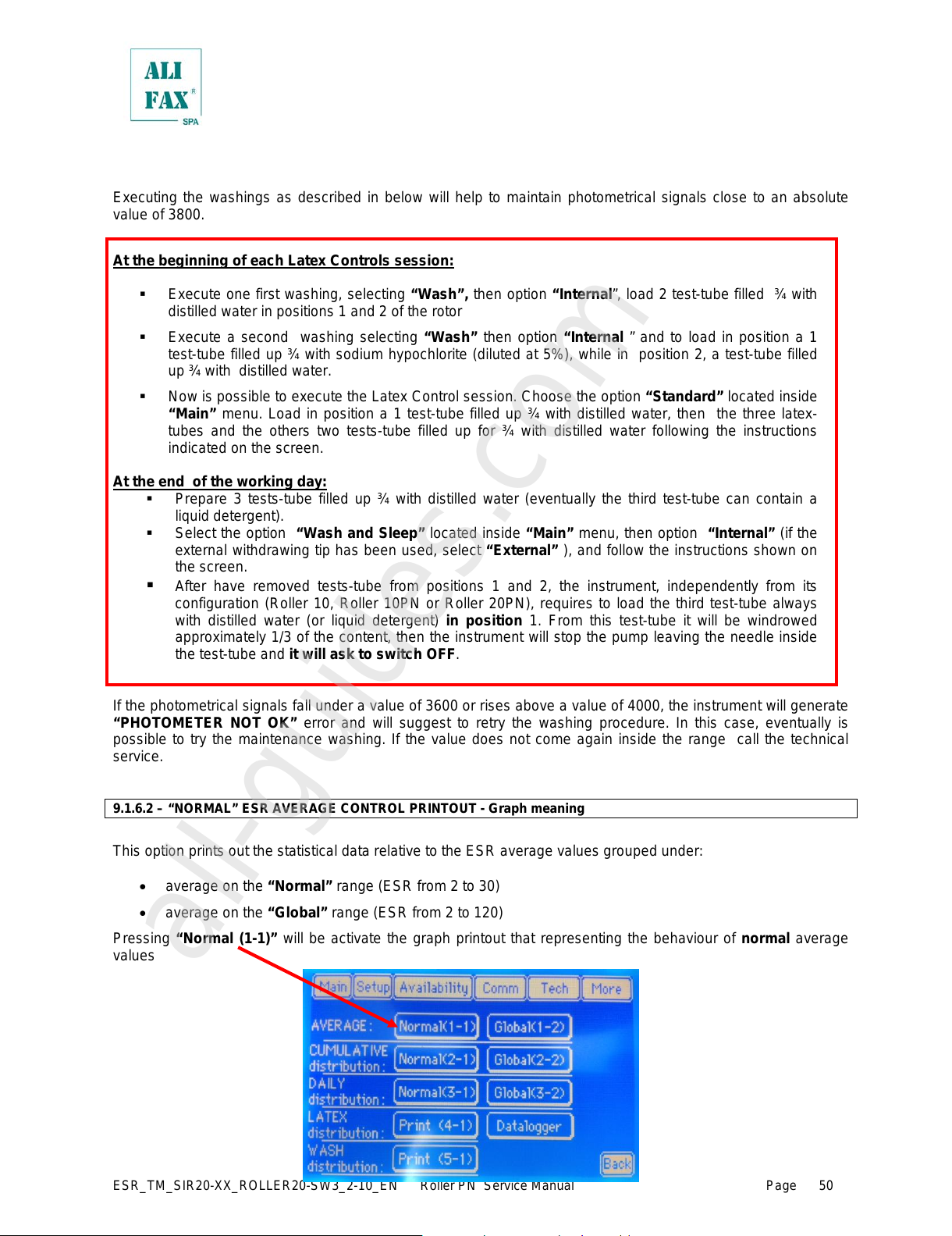
ESR_TM_SIR20-XX_ROLLER20-SW3_2-10_EN Roller PN Service Manual Page
50
Executing the washings as described in below will help to maintain photometrical signals close to an absolute
value of 3800.
At the beginning of each Latex Controls session:
Execute one first washing, selecting “Wash”, then option “Internal”, load 2 test-tube filled ¾ with
distilled water in positions 1 and 2 of the rotor
Execute a second washing selecting “Wash” then option “Internal ” and to load in position a 1
test-tube filled up ¾ with sodium hypochlorite (diluted at 5%), while in position 2, a test-tube filled
up ¾ with distilled water.
Now is possible to execute the Latex Control session. Choose the option “Standard” located inside
“Main” menu. Load in position a 1 test-tube filled up ¾ with distilled water, then the three latex-
tubes and the others two tests-tube filled up for ¾ with distilled water following the instructions
indicated on the screen.
At the end of the working day:
Prepare 3 tests-tube filled up ¾ with distilled water (eventually the third test-tube can contain a
liquid detergent).
Select the option “Wash and Sleep” located inside “Main” menu, then option “Internal” ( if the
external withdrawing tip has been used, select “External” ), and follow the instructions shown on
the screen.
After have removed tests-tube from positions 1 and 2, the instrument, independently from its
configuration (Roller 10, Roller 10PN or Roller 20PN), requires to load the third test-tube always
with distilled water (or liquid detergent) in position 1. From this test-tube it will be windrowed
approximately 1/3 of the content, then the instrument will stop the pump leaving the needle inside
the test-tube and it will ask to switch OFF.
If the photometrical signals fall under a value of 3600 or rises above a value of 4000, the instrument will generate
“PHOTOMETER NOT OK” error and will suggest to retry the washing procedure. In this case, eventually is
possible to try the maintenance washing. If the value does not come again inside the range call the technical
service.
9.1.6.2 – “NORMAL” ESR AVERAGE CONTROL PRINTOUT - Graph meaning
This option prints out the statistical data relative to the ESR average values grouped under:
• average on the “Normal” range (ESR from 2 to 30)
• average on the “Global” range (ESR from 2 to 120)
Pressing “Normal (1-1)” will be activate the graph printout that representing the behaviour of normal average
values
All manuals and user guides at all-guides.com
all-guides.com
Page 57
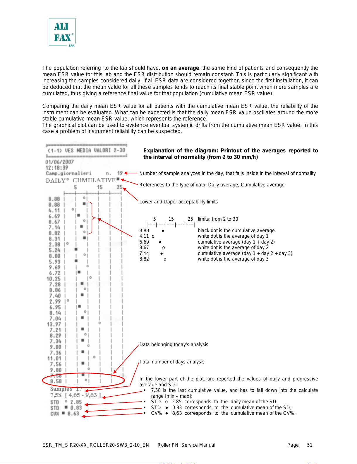
ESR_TM_SIR20-XX_ROLLER20-SW3_2-10_EN Roller PN Service Manual Page
51
The population referring to the lab should have, on an average, the same kind of patients and consequently the
mean ESR value for this lab and the ESR distribution should remain constant. This is particularly significant with
increasing the samples considered daily. If all ESR data are considered together, since the first installation, it can
be deduced that the mean value for all these samples tends to reach its final stable point when more samples are
cumulated, thus giving a reference final value for that population (cumulative m ean ESR value).
Comparing the daily mean ESR value for all patients with the cumulative mean ESR value, the reliability of the
instrument can be evaluated. What can be expected is that the daily mean ESR value oscillates around the more
stable cumulative mean ESR value, which represents the reference.
The graphical plot can be used to evidence eventual systemic drifts from the cumulative mean ESR value. In this
case a problem of instrument reliability can be suspected.
Explanation of the diagram: Printout of the averages reported to
the interval of normality (from 2 to 30 mm/h)
Number of sample analyzes in the day, that falls inside in the interval of normality
References to the type of data: Daily average, Cumulative average
Lower and Upper acceptability limits
5 15 25 limits: from 2 t o 30
|-----|-----|-----|-----|-----|
8.88 ● black dot is the cumulative average
4.11 o white dot is the average of day 1
6.69 ● cumulative average (day 1 + day 2)
8.67 o white dot is the average of day 2
7.14 ● cumulative average (day 1 + day 2 + day 3)
8.82 o white dot is the average of day 3
Data belonging today’s analysis
Total number of days analysis
In the lower part of the plot, are reported the values of daily and progressive
average and SD:
7,58 is the last cumulative value, and has to fall down into the calculate
range [min – max];
STD o 2.85 corresponds to the daily mean of the SD;
STD ● 0.83 corresponds to the cumulative mean of the SD;
CV% ● 8,63 corresponds to the cumulative mean of the CV%.
All manuals and user guides at all-guides.com
Page 58

ESR_TM_SIR20-XX_ROLLER20-SW3_2-10_EN Roller PN Service Manual Page
52
The stability with time of the mean value of “normal population” is not affected by the percentage of pathological
samples that can vary from day to day, influencing the variation of the Mean ESR value. Normal population of
today and normal population of tomorrow will have distribution and mean ESR value v ery close.
9.1.6.3 – “GLOBAL” ESR AVERAGE CONTROL PRINTOUT - Graph meaning
This option prints out the statistical data relative to the ESR average values grouped under:
• average on the “Normal” range (ESR from 2 to 30)
• average on the “Global” range (ESR from 2 to 120)
Pressing “Global (1-2)” will be activate the graph printout that representing the behaviour of global average
values
Explanation of the diagram: Printout of the averages reported to
global range (from 2 to 120 mm/h)
Number of samples, analyzed in the day, that falls inside the global range (2-120)
References to the type of data: Daily average, Cumulative average
Lower and Upper acceptability limits
5 15 25
|-----|-----|-----|-----|-----|
8.88 ● black dot is the cumulative average
4.11 o white dot is the average of day 1
6.69 ● cumulative average (day 1 + day 2)
8.67 o white dot is the average of day 2
7.14 ● cumulative average (day 1 + day 2 + day 3)
11.48 o white dot is the average of day 3
Data belonging today’s analysis
Total number of days analysis
In the lower part of the plot, are reported the values of daily and progressive
average and SD:
STD o 4.31 corresponds to the daily mean of the SD;
STD ● 1.34 corresponds to the cumulative mean of the SD;
CV% ● 10,37 corresponds to the cumulative mean of the CV%.
All manuals and user guides at all-guides.com
Page 59

ESR_TM_SIR20-XX_ROLLER20-SW3_2-10_EN Roller PN Service Manual Page
53
Even if the two diagrams, apparently looks equal, the fact that in this diagram are
considered ALL the samples in the interval 2-120, means this diagram is more
sensible to variations, in fact comparing the statisti cal data of trend the 2-30 and
trend the 2-120 is possible to notice the differences.
Guide to the interpretation of the diagram and statistical/clinical meaning
What reported on the previous pages still more meaningful if referred to the “normal population” if referred to the
stability, along the time, of the average of the ESR values in the normality range. The average ESR and
distribution of the normal values is without doubt more stable than the average and the distribution of the global
values, because in the global case are considered all the patients day after day can come from various ward
units, from particular ward units etc. It must also be remembered that the patients with ESR values in the normal
range are also, of usual, the majority of the samples who reach the laboratory.
This option must be considered like an analytical control based “on the population of the samples „ and it
presupposes the role of the control of the instrument. This kind of control can be considered like a continuous
calibration of the instrument.
For a sufficient number of samples, it can be always considered that in a laboratory with the same instrument, the
distribution of the ESR values and the average ESR value, should not oscillate in a meaningful way, if the
analytical performances of the instrument are sure.
It is reasonable think that in general terms the samples who arrive in the same laboratory, represent a constant
population that refers to the laboratory and that this population will maintain a constancy distribution of the ESR
values, especially if the number of samples considered you is statistically meaningful. The mean value of the ESR
of the population, therefore like the ESR distribution, can be used like “standard, in order to control the reliability
of the instrument.
All manuals and user guides at all-guides.com
Page 60

ESR_TM_SIR20-XX_ROLLER20-SW3_2-10_EN Roller PN Service Manual Page
54
9.1.6.3.b – INTERPRETATION OF THE STATISTICAL MEANING
Interpreting the statistical printout of the data.
Data that belong to 30ts day
The printout corresponds to the mean and progressive ESR that is obtained selecting
from the Main Menù, the option Q.C. and then the pressing “Normal”
The trend of the behaviour of the daily average progressiv e ESR of all the samples
will be similar to that one shown to side:
(1-1) Daily samples inside the range 2 - 30
This graphical printout represents the last 30 days of analysis, and an anomalous
tendency of daily average respect the cumulative average, can be easi ly evidenced,
thus alerting the user for a possible systemic error or instr ument problem. The data
are shown from oldest (on the top) to most recent (on bottom of graph).
Be careful in interpreting the data to consider the number of samples of the day
and an eventual different source of samples. The cumulative average line
becomes stable after a certain point (more than 100 s amples) and the daily average
moves around the cumulative trend line. In this way a problem on instrument could be
immediately evidenced by a rapid deflection of the trend line of daily and cumulat ive
averages.
The instrument is able to collect 6000 samples for calculate the average, so also
large variations on daily statistics will not change in determinant way the cumulative
average. On the opposite side, as s oon as it reaches 6000 sampl es, i t will discard the
first 1000 (using the FIFO rule), coming back to 5000 samples to avoid that the
cumulative average trend becomes too much stable to be moved.
Data belonging today’s analysis
Total number of days analysis
At the end of the graph, the Standard Deviations of cumulative average and daily
average are printed:
7,58 is the last cumulative value, and has to fall down into the calculate range
[min - max];
[min = mean of all cumulative values – 3 x cumulative STD ●]
[max = mean of all cumulative values + 3 x cumulative STD ●]
STD o 2.85 corresponds to the daily mean of the SD;
STD ● 0.83 corresponds to the cumulative mean of the SD;
CV% ● 8,63 corresponds to the cumulative mean of the CV%.
From a statistical point of view, data can be considered stable if it stays between three Standard Deviations of the ref erence
population. In this case, taking the last cumulativ e average data (7.58) and the three standard dev iations of the daily average
(cumulative STD x 3 0.83 x 3 = 2.49), we can say that the last daily average is in range if don't exceeds the three standard
deviations of the cumulative data. In this example, the mean of all cumul ative values, except the last one (daily value), is
(7.14), and so the lower limit it will be (7.14 – 2.49 = 4,65), and the upper limit it will be (7.14 + 2.49 = 9,63). In this case, the
daily cumulative value (7.58) falls between the lower and upper limits, so the instrument is working properly.
Remember that if this doesn't happen, the c ause should be searched on the samples processed during the day and from the
kind of patients analyzed (a lot of pathological or a lot of healthy patients). T his first graph is referred to all the ESR results
from 2 to 30, and this data can be highly instable. For this reason, also the next graph is printed out.
All manuals and user guides at all-guides.com
Page 61

ESR_TM_SIR20-XX_ROLLER20-SW3_2-10_EN Roller PN Service Manual Page
55
.
This according to plot look identical to the previous one, but in this case the
analysis covers the entire ESR results comprised between 2 - 120, t his means the
GLOBAL range of values.
This plot is slightly less stable, because data that compose it includes also the
pathological patients.
As is possible to see, even without changing the total data analyzed, the diagram is
slightly less stable because in this case appears average data that tends to m ove
upwards the daily ESR average and consequently also the daily and cumulative SD
raises.
All manuals and user guides at all-guides.com
all-guides.com
Page 62

ESR_TM_SIR20-XX_ROLLER20-SW3_2-10_EN Roller PN Service Manual Page
56
9.1.6.4 – “NORMAL” CUMULATIVE ESR DISTRIBUTION PRINTOUT - Graph meaning
This option prints out the statistical data relative to the cumulative ES R v al ues grouped under:
• cumulative on the “Normal” range (ESR from 2 to 30)
• cumulative on the “Global” range (ESR from 2 to 120)
Pressing “Normal (2-1)” will be activate the graph printout that representing the behaviour of normal cumulative
values
Interpretation of the diagram: Printout of the normal cumulative
ESR distribution (from 2 to 30 mm/h)
Total Number of samples, inside the normality interval
Statistical data: Average and SD of the data analyzed.
The mean and SD values refers to the data in the interv al 2-30.
As it can be seen, the instrument generates a statistical r eport in which the ESR
results are redistributes in subintervals (of the normal interval 2-30)
For each subinterval is available:
limits of the interval
percentage of samples in each interval
number of samples analyzed that belong to each subinterval
All manuals and user guides at all-guides.com
Page 63

ESR_TM_SIR20-XX_ROLLER20-SW3_2-10_EN Roller PN Service Manual Page
57
9.1.6.5 – “GLOBAL” CUMULATIVE ESR DISTRIBUTION PRINTOUT - Graph meaning
This option prints out the statistical data relative to the cumulative ESR v al ues grouped under:
• cumulative on the “Normal” range (ESR from 2 to 30)
• cumulative on the “Global” range (ESR from 2 to 120)
Pressing “Global (2-2)” will be activate the graph printout that representing the behaviour of global cumulative
values
Interpretation of the diagram: Printout of the global cumulative
ESR distribution (from 2 to 120 mm/h)
Total Number of samples, inside the “global” interval
Statistical data: Average and SD of the data analyzed.
The mean and SD values refers to the data in the interv al 2-120.
As it can be seen, the instrument generates a statistical r eport in which the ESR
results are redistributes in subintervals (of the normal interval 2-120)
For each subinterval is available:
limits of the interval
percentage of samples in each interval
number of samples analyzed that belong to each subinterval
It is important to notice that in “Global” distribut ion the int ervals do not match the
intervals defined for the “Normal” distribution neither in number of samples, in
fact it’s natural expecting that t he total number of samples analyzed will be higher
than those considered in the “Normal” distribution, because in the global
distribution are considered all the samples between 2 and 120, while in the normal
distribution only the samples between 2 and 30
All manuals and user guides at all-guides.com
Page 64

ESR_TM_SIR20-XX_ROLLER20-SW3_2-10_EN Roller PN Service Manual Page
58
9.1.6.6 – “NORMAL” DAILY ESR DISTRIBUTION PRINTOUT - Graph meaning
This option prints out the statistical data relative to the daily ESR distribution values grouped under:
• daily on the “Normal” range (ESR from 2 to 30)
• daily on the “Global” range (ESR from 2 to 120)
Pressing “Normal (3-1)” will be activate the graph printout that representing the behaviour of normal values
Interpretation of the diagram: Printout of the normal daily ESR
distribution (from 2 to 30 mm/h)
Daily samples, inside the normality interval
Statistical data: Average and SD of the data analyzed.
The mean and SD values refers to the data in the interv al 2-30.
As it can be seen, the instrument generates a statistical r eport in which the ESR
results are redistributes in subintervals (of the normal interval 2-30)
For each subinterval is available:
limits of the interval
percentage of samples in each interval
number of samples analyzed that belong to each subinterval
All manuals and user guides at all-guides.com
Page 65
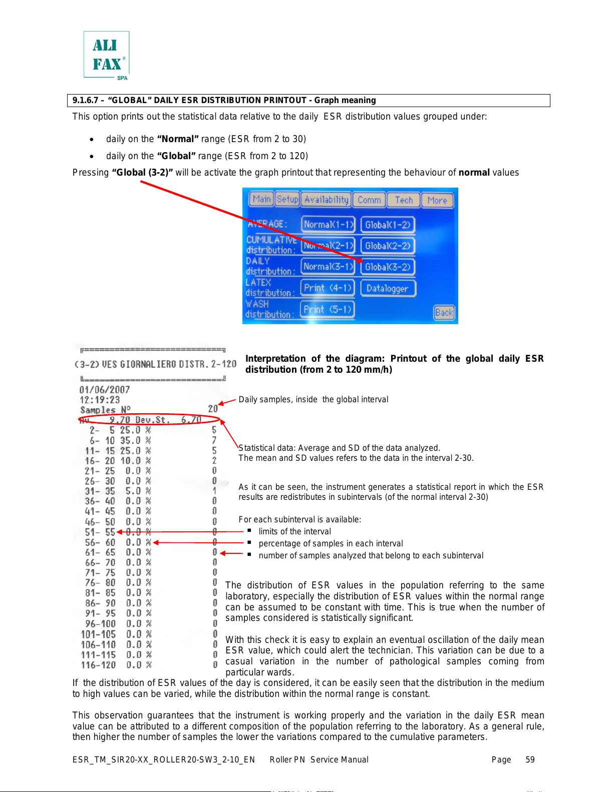
ESR_TM_SIR20-XX_ROLLER20-SW3_2-10_EN Roller PN Service Manual Page
59
9.1.6.7 – “GLOBAL” DAILY ESR DISTRIBUTION PRINTOUT - Graph meaning
This option prints out the statistical data relative to the daily ESR distribution values grouped under:
• daily on the “Normal” range (ESR from 2 to 30)
• daily on the “Global” range (ESR from 2 to 120)
Pressing “Global (3-2)” will be activate the graph printout that representing the behaviour of normal values
Interpretation of the diagram: Printout of the global daily ESR
distribution (from 2 to 120 mm/h)
Daily samples, inside the global interval
Statistical data: Average and SD of the data analyzed.
The mean and SD values refers to the data in the interv al 2-30.
As it can be seen, the instrument generates a statistical r eport in which the ESR
results are redistributes in subintervals (of the normal interval 2-30)
For each subinterval is available:
limits of the interval
percentage of samples in each interval
number of samples analyzed that belong to each subinterval
The distribution of ESR values in the population referring to the same
laboratory, especially the distribution of ESR values within the normal range
can be assumed to be constant with time. This is true when the number of
samples considered is statistically significant.
With this check it is easy to explain an eventual oscillation of the daily mean
ESR value, which could alert the technician. This variation can be due to a
casual variation in the number of pathological samples coming from
particular wards.
If the distribution of ESR values of the day is considered, it can be easily seen that the distribution in the medium
to high values can be varied, while the distribution within the normal range is constant.
This observation guarantees that the instrument is working properly and the variation in the daily ESR mean
value can be attributed to a different composition of the population referring to the laboratory. As a general rule,
then higher the number of samples the lower the variations compared to the cumulative parameters.
All manuals and user guides at all-guides.com
Page 66

ESR_TM_SIR20-XX_ROLLER20-SW3_2-10_EN Roller PN Service Manual Page
60
9.1.6.8 –INSTRUMENT VERIFICATION USING THE LATEX CONTROL KIT
The Latex Controls kit (
Ord. code SI 305.100-A/SI 305.102-A or SI 305.300-A/ SI 305.302-A) is a valid tool for the
functional verification of the analyser Roller 10. The results of the control simulate three ESR values, a first level
(around 9 mm/h), one intermediate level (around 19 mm/h) and a high level (around 65 mm/h). By comparing the
results obtained from the analyzer with those reported on the kit package it will be very easy to control if the
instrument is reporting reliable results or not. In this way, the instrument can be kept monitored during its whole
operational life.
Before of the execution of the latex c ontrols, the instrument demands a washing procedure using two washing
tubes filled ¾ with distilled water as described in previous chapters.
It is necessary to follow the instructions for use included into the Latex Controls kit and at the end of the
procedure compare the printed results from the analyzer against the values reported in Table 2 on the package
kit box: if the results obtained by analyser fits the expected range reported on Table 2 , it means that the analyzer
is calibrated.
On the contrary, if one or more results are different from the ones reported on the kit package, it is recommended
to call the Technical Service for a functional verification and calibration of the apparatus.
Below is reported the procedure used to check instrument using Latex Control kit
At the beginning of each Latex Controls session:
Execute one first washing, selecting “Wash”, then option “Internal / External” (depending the
circuit to be controlled), load 2 test-tube filled ¾ with distilled water in positions 1 and 2 of the rotor
Execute a second washing selecting “Wash” then option “Internal / External” (depending the
circuit to be controlled), load in position a 1 test-tube filled up ¾ with sodium hypochlorite (diluted at
5%), while in position 2, a test-tube filled up ¾ with distilled water.
Now is possible to execute the Latex Control session. Choose the option “Standard” located inside
“Main” menu. Load in position a 1 test-tube filled up ¾ with distilled water, then the three latex-
tubes and the others two tests-tube filled up for ¾ with distilled water following the instructions
indicated on the screen.
At the end of the working day:
Prepare 3 tests-tube filled up ¾ with distilled water (eventually the third test-tube can contain a
liquid detergent).
Select the option “Wash and Sleep” located inside “Main” menu, then option “Internal /
External” (depending the circuit to be washed), load 2 test-tube filled ¾ with distilled water in
positions 1 and 2 of the rotor; if external withdrawing tip has been used just follow the instructions
shown on the screen.
After have removed tests-tube from positions 1 and 2, the instrument, independently from its
configuration (Roller 10, Roller 10PN or Roller 20PN), requires to load the third test-tube always
with distilled water (or liquid detergent) in position 1. From this test-tube it will be windrowed
approximately 1/3 of the content, then the instrument will stop the pump leaving the needle inside
the test-tube and it will ask to switch OFF.
Results obtained during the latex control
procedure are stored by the instrument; it is
therefore possible to print out a report pressing
the key “Print (4-1)”. With this option it is
possible to visualize the tendency of the
instrument and being able to find eventual drifts
that will require an accurate control of the
instrument. The graphical printout cover the last
30 days.
All manuals and user guides at all-guides.com
all-guides.com
Page 67

ESR_TM_SIR20-XX_ROLLER20-SW3_2-10_EN Roller PN Service Manual Page
61
The trend of the latex must be interpreted as a tendency pointer.
The starting reference are the values obtained during the calibration and
then, for every control executed with the Latex Kit, the trend will show how
much the read latex values drifts from the reference values printed on the
box and also on the printout report generated during each control procedure.
Analyzing the diagram it is possible to observe that:
For each sensor there is a reference marker which represents the drift from
the reference (1) obtained from the analyzer against the reference values.
This trend, when is completely full, represents a maximum of 30 days of
analysis, therefore anomalous tendency in the daily values, against the
reference is easily identifiable. Consequently the customer is able to
understand if there is systematic error or an instrument error. Data are
shown from the oldest (lower part) to the most recent (upper part of the
diagram).
Explication of the printout report:
-20 -10 1
+10 +20
DEV % |------------|------------|-----------|-----------|
0 | | ● | |
0 | |
o | |
0 | |
● | |
8 | | |
o | |
1 | | |
● | |
1 | | |
o | |
-2 | |
● | | |
-4 | |
o | | |
-2 | |
● | | |
4 | | |
o | |
Sens
● AV 1,22 - STD: 0,47
Sens o AV 2,55 - STD: 0,48
In order to better understand the meaning of the results
printed out, imagine a series of three controls with values
of 9, 19 and 65 mm/h (values of reference). Executing the
control of the analyzer, if the values will be identical
(9, 19
and 65 that is the ideal case), there won't be a shift (y=1.00*x)
and the dots symbol will printed exactly on the column 1, as on
the first line on the aside graph. On the contrary, if the result s are
for example 10, 21 and 70 mm/h, the shift would be +8,00%
(y=1.08*x) and the dots will be positioned between column 1 and
column +10%, like the fourth white dot in the graph aside.
At the bottom are printed out the Average of DEV% values (AV)
and the Standard Deviation (STD).
All manuals and user guides at all-guides.com
Page 68

ESR_TM_SIR20-XX_ROLLER20-SW3_2-10_EN Roller PN Service Manual Page
62
Results obtained during the latex calibration
procedure are stored by the instrument; it is
therefore possible to print out a report pressing
the key “Datalogger”. With this option it is
possible to visualize precise information about all
calibrations done, like the LOT and the KIT of the
triplet, the date of withdrawal, old and new Model
Fact1 and Model Fact 2, the type of withdrawal
and if the flag priming latex is on or off
Printout explanation:
LOT number, KIT number, date of withdrawal
Mfact1 old -> new (value of Model Fact1 pre and post calibration)
Mfact2 old -> new (value of Model Fact1 pre and post calibration)
DAC1 old -> new (value of DAC1 pre and post calibration)
DAC2 old -> new (value of DAC2 pre and post calibration)
DACSTOP old -> new (value of DACSTOP pre and post calibration)
Ext circuit: 0 or 1 (0 = calibration done with internal withdrawal)
(1 = calibration done with external withdrawal)
Prim latex: 0 or 1 (0 = calibration done with priming latex disable)
(1 = calibration done with priming latex enable)
Code: 1 or 2 or 3 (1 = ID inserted manually)
(2 = ID inserted with “Memo” button)
(3 = ID inserted with External Barcode Reader)
All manuals and user guides at all-guides.com
Page 69

ESR_TM_SIR20-XX_ROLLER20-SW3_2-10_EN Roller PN Service Manual Page
63
9.1.6.9 – ERASE STATISTICAL DATABASE
To erase statistical database, it is necessary to be logged as Technical User
To login is necessary to access Setup and “Log In-out”, then press “LOGIN”
and type the appropriate password (1990 for technical level).
press the “LEFT ARROW” and then “BACK”. On the MAIN SCREEN will be indicated the level of login: User or
Technical level”.
Pressing “Q.C.”, (from Main Menu) the instrument, in case of Roller instrument having two independent reading
units has also two independent statistical databases so before getting access to the statistics options it is
necessary select the circuit of interest:
All manuals and user guides at all-guides.com
Page 70

ESR_TM_SIR20-XX_ROLLER20-SW3_2-10_EN Roller PN Service Manual Page
64
After that, instrument displays the Statistical Main Menu
Then from Main Menu select “Q.C.”, the instrument will display the following image:
Now just press “Res.” To erase desired statistical database. Each database is independent so, to erase all
database it is necessary to press “Res.“ for each one of them.
For the 2 latex database, “Print (4-1) and “Datalogger”, when pressed “Res.” also Datalogger database will be
erased.
At the end press “Back” to return to main menu.
All manuals and user guides at all-guides.com
Page 71

ESR_TM_SIR20-XX_ROLLER20-SW3_2-10_EN Roller PN Service Manual Page
65
9.2 – SETUP MENU
Setup Menu:
Pressing “Setup” from the MAIN SCREEN, the instrument shows the following options
In case of Roller instrument having two independent reading units, before accessing the CPS parameters
is necessary to select the circuit of interest:
After having done the selection, the following menus are identical; they reports the configuration for the internal or
external circuit.
9.2.1 – CPS MENU
CPS:
This function’s accessibility is linked to a password level.
Pressing “CPS” (in the Setup Menu) without any password level activated, the instrument will display:
9.2.1.1 – CPS’ PARAMETERS
Then pressing “Parameters” will be displayed CPS’s parameter but without the possibility to modify anything as
showed in the next image:
All manuals and user guides at all-guides.com
all-guides.com
Page 72

ESR_TM_SIR20-XX_ROLLER20-SW3_2-10_EN Roller PN Service Manual Page
66
9.2.1.1.a – MODIFY TYPE OF REFERENCE (CHOOSE BOOSTERY TYPE) (Technical password required)
As stated before, to have the possibility to modify this parameter it is necessary to be logged as “technical
level” (with full access to the functions) otherwise the instrument will not allow to access the functi on.
To login is necessary to access Setup and “Log In-out”, then press “LOGIN” and type the appropriate
password (1990 for technical level).
This function allows to choose the type of reference that the instrument uses. Be careful that, once the
reference was choose, is recommended to not changing it anymore.
After pressed “SET” to choose the type of reference, the instrument asks to confirm, so if is pressed “NO” or
“Back” button the instrument comes back to CPS menu, otherwise if is pressed “YES” the instrument allows to
choose the reference:
In fact is possible to choose the reference just pressing “EDTA” (for EDTA BoosterY) or “Sodium Citrate” (for
Sodium Citrate BoosterY) and finally press “OK” :
Then the instrument will display again the previous image with the current reference.
All manuals and user guides at all-guides.com
Page 73
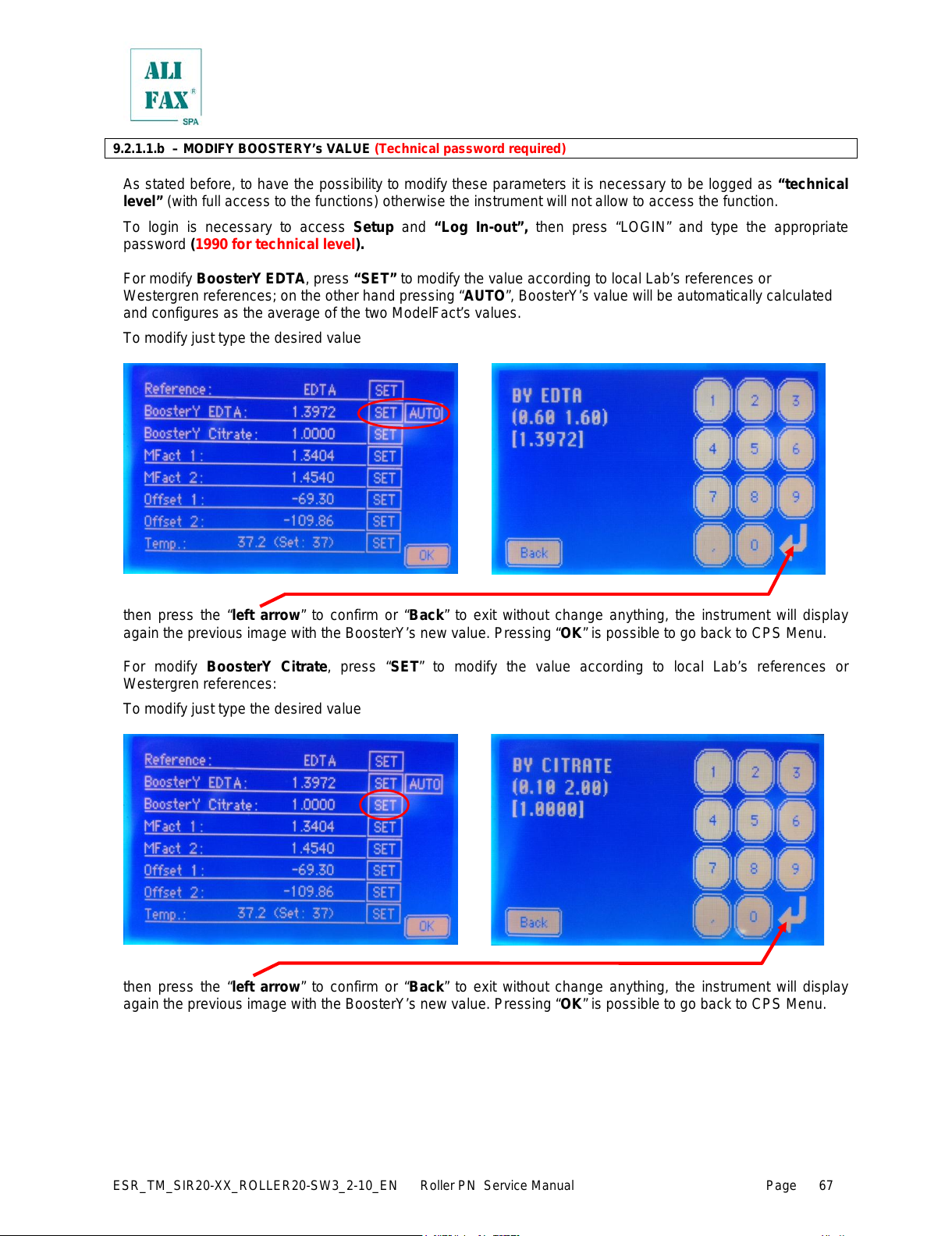
ESR_TM_SIR20-XX_ROLLER20-SW3_2-10_EN Roller PN Service Manual Page
67
9.2.1.1.b – MODIFY BOOSTERY’s VALUE (Technical password required)
As stated before, to have the possibility to modify these parameters it is necessary to be logged as “technical
level” (with full access to the functions) otherwise the instrument will not allow to access the function.
To login is necessary to access Setup and “Log In-out”, then press “LOGIN” and type the appropriate
password (1990 for technical level).
For modify BoosterY EDTA, press “SET” to modify the value according to local Lab’s references or
Westergren references; on the other hand pressing “AUTO”, BoosterY’s value will be automatically calculated
and configures as the average of the two ModelFact’s values.
To modify just type the desired value
then press the “left arrow” to confirm or “Back” to exit without change anything, the instrument will display
again the previous image with the BoosterY’s new value. Pressing “OK” is possible to go back to CPS Menu.
For modify BoosterY Citrate, press “SET” to modify the value according to local Lab’s references or
Westergren references:
To modify just type the desired value
then press the “left arrow” to confirm or “Back” to exit without change anything, the instrument will display
again the previous image with the BoosterY’s new value. Pressing “OK” is possible to go back to CPS Menu.
All manuals and user guides at all-guides.com
Page 74

ESR_TM_SIR20-XX_ROLLER20-SW3_2-10_EN Roller PN Service Manual Page
68
9.2.1.1.c – MODIFY WHOLE PARAMETRES’ VALUES
Once logged as Technical Service is possible to modify all CPS setup value
IT IS VERY IMPORTANT TO UNDERSTAND THAT MODIFYING ONE OR MORE OF THESE PARAMETERS
CAN AFFECT INSTRUMENT’S PERFORMANCES AND CAN CAUSE AN INCORRECT BLOOD ANALYSIS
RESULTS.
TECHNICIANS THAT MODIFY THESE PARAMETERS MUST KNOW VERY WELL THE FUNCTIONALITY OF
EACH ONE OF THESE PARAMETERS.
IN ANY CASE IS STRONGLY RECOMMENDED TO PRINTOUT A FLAG LIST BEFORE DOING ANY
VARIATION ON THIS OPERATIVE PARAMETERS.
9.2.1.1.d – MODIFY MODEL FACT’s VALUES (Technical password required)
To modify each one of the two ModelFact values press “SET” to access each one of the parameters
configuration page, where is possible so set manually the desired value. As explained before, numbers are typed
using the keyboard.
To modify just type the desired value
then press the “left arrow” to confirm or “Back” to exit without change anything, the instrument will display
again the previous image with the new Model Fact value. Pressing “OK” is possible to go back to CPS Menu.
9.2.1.1.e – MODIFY Offset Sensors VALUES (Technical password required)
To modify each one of the two Offset sensors values press “SET” to access each one of the parameters
configuration page, where is possible so set manually the desired value. As explained before, numbers are typed
using the keyboard.
To modify just type the desired value
In this case, due to the Offset can be positive or negative, first type the number and then press +/- if you need a
negative reference, then press the “left arrow” to confirm or “Back” to exit without change anything, the
instrument will display again the previous image with the new Offset value. Pressing “OK” is possible to go back
to CPS Menu.
All manuals and user guides at all-guides.com
Page 75

ESR_TM_SIR20-XX_ROLLER20-SW3_2-10_EN Roller PN Service Manual Page
69
9.2.1.1.f – MODIFY THERMOSTAT reference value (Technical password required)
To modify thermostat sensor reference value press “SET” to access configuration page, where is possible so set
manually the desired temperature. As explained before, numbers are typed using the keyboard.
To modify just type the desired value
then press the “left arrow” to confirm or “Back” to exit without change anything, the instrument will display
again the previous image with the new Model Fact value. Pressing “OK” is possible to go back to CPS Menu.
9.2.1.2 – CPS Correctors Parameters (Available only if a Multiparametric card is used) (Technical password required)
This function is conceptually similar to BoosterY; the main difference is it allows to change the “gain” of the
other supplementary parameters the instrument is able to measure. The supplementary parameters are
enabled by means of a “Multiparametric Card” loaded on the instrument.
Field Engineers logged as Technical Service User can have access to this page and check the configuration of
the gain of each one of the parameters. By default all the values are set at 1. 0000 and MUST REMAIN AT 1.
To change the value of a parameter, press “SET” to access configuration page, where is possible so set
manually the desired value. Numbers are typed using the keyboard;
To modify just type the desired value then press the
“left arrow” to confirm or “Clear” to exit without
change anything, the instrument will display again the
previous image with the new Model Fact value.
Pressing “Back” is possible to go back to CPS Menu.
All manuals and user guides at all-guides.com
Page 76

ESR_TM_SIR20-XX_ROLLER20-SW3_2-10_EN Roller PN Service Manual Page
70
9.2.1.3 – CPS Read ADC
This function allow technician to verify CPS’s Analog-Digital Converters reference (without the possibility to
modify anything if not logged as technical service)
Pressing “Read ADC” will be displayed CPS’s Analog-Digital Converters reference (without the possibility to
modify anything if not logged as technical service).
DAC: which is changeable refers to the power emitted by the LED inside the reading unit. This value changes
every time a latex procedure is done and the change is adjusted in order to obtain a value of DAC which
guarantees a water value as close as possible to the reference value of 3800 (printed out during washing
procedure). DAC reference number goes from 0 to 1023; normal working range goes from 500 to 800,.
ADC: refers to the effective value that each sensor reads (in other words is the sensibility of the sensor) , in this
case this value changes continuously and each value is independent from the others. ADC reference
number goes from 0 to 4095. There is no specific working range even if the normal value should
be around 2000 - 2200
To modify DAC’s values proceed as described for the others examples, for each sensor appears a keyboard in
which the technician can set the desired value. Values goes from 0 to 1023.
9.2.1.4 – FIRST UP
Please refer to chapter 10
9.2.2 – MIX MENU
All manuals and user guides at all-guides.com
all-guides.com
Page 77

ESR_TM_SIR20-XX_ROLLER20-SW3_2-10_EN Roller PN Service Manual Page
71
Pressing “Mix” (in the Setup Menu), the instrument will display:
this function allow the user to set:
• The desired number of rotations: pressing “set” the instrument will display a keyboard where the
operator can type the desired number of rotations (from 2 up to 1000), then pressing the “left arrow”
confirm the new value.
• The desired mixing speed: “low”, “med” or “high”; just press the desired speed “button”
• The desired number of Cycles Centrifugations (for pediatric mode): pressing “set” the instrument will
display a keyboard where the operator can type the desired number of cycles (from 2 up to 100), then
pressing the “left arrow” confirm the new value.
• by default the instrument is set up at medium speed, 140 cycles and 30 centrifugation cycles.
Finally the operator can check practically the rotor speed, by pressing “Go”, in this case the rotor being to rotate
and will still rotate up when the “Stop” is pressed.
Pressing “Back” the instrument will go back and will display the Main Screen.
9.2.3 – DATE TIME MENU
This function’s accessibility is linked to a password level.
Without a password
Pressing “Date time” (in the Setup Menu), the instrument will display:
9.2.3.1 – MODIFY DATE TIME VALUE (User level password required)
All manuals and user guides at all-guides.com
Page 78

ESR_TM_SIR20-XX_ROLLER20-SW3_2-10_EN Roller PN Service Manual Page
72
As stated before, to have the possibility to modify these parameters it is necessary to be logged as “user level”
otherwise the instrument will not allow to access the function.
To login is necessary to access Setup and “Log In-out”, then press “LOGIN” and type this password: 1010,
press the “LEFT ARROW” and then “BACK”. On the MAIN SCREEN will be indicated “LOGIN: user level”.
User level allow to modify date and time values:
Pressing “SET” the instrument allow to modify DATE or TIME values;
• If the change is applied to DATE, the instrument will ask to modify in the following order: Year, Month and
Day to modify just type the desired value;
• If the change is applied to TIME, the instrument will ask to modify in the following order: Hour, and Minute
to modify just type the desired value.
then press the “left arrow” to confirm or “Back” to exit without change anything, the instrument will display
again the previous image with the DATE or TIME new value. Pressing “Back” is possible to go back to MAIN
SCREEN.
All manuals and user guides at all-guides.com
Page 79

ESR_TM_SIR20-XX_ROLLER20-SW3_2-10_EN Roller PN Service Manual Page
73
9.2.4 – FL (Flag List) MENU
Pressing “FL” (in the
Setup Menu), the
instrument will printout
the Flag List of both
reading Units
In the Flag List are
printed out all the
operational parameters
of the instrument.
UNIT INTERFACE
Date and time of the software compilation
Instrument serial number
Debug (ON or OFF) (Only Technical Service)
Threshold level for Maintenance intervention requesting. (Only Technical Service) reference value:
30000
Maintenance counter, counts the number of analyses
Threshold (in minutes) for automatic washing. ( O nly Technical Service) reference value 60
patient ID and ESR results printing on real time (ON or OFF)
IDs and ESR results on double height printing (ON or OFF)
Specify if 1 or 2 CPS are installed on the instrument (Only Technical Service)
Specify if the latex priming is enabled or not (Only Technical Service) by default is enabled
Specify if pediatric samples are enabled or not (Onl y Technical Service)
Test availability for the ESR and other parameters analysis
ESR and other parameters counter of executed test
Smart warning (Only Technical Service) reference value 1000
Smart personalization (distributor name)
MOTOR BOARD
Motor Board Software version.
Date and time of the Motor Board software compilati on.
Number of mixing revolutions, from 2 to 1000.
Mixing speed, 1=60 RPM (default), 2=32 RPM and 3=26 RPM
Withdrawal volume of blood in automatic sampling, reference value 175
Withdrawal volume of blood in manual sampling, reference value 100
Upward steps done by syringe in automatic sampling, reference val ue 3450
Upward steps done by syringe in washing procedure, reference value 4500
Tube offset, (used to align rotor in front of loading sensors), reference value 0
Syr Fast, define if the syringe moves up-down slow or fast reference value OFF
Centrifugation cycles, number of cycles for pediatric samples, from 2 to 100
All manuals and user guides at all-guides.com
Page 80

ESR_TM_SIR20-XX_ROLLER20-SW3_2-10_EN Roller PN Service Manual Page
74
CPS BOARD (INTERNAL)
Analogical Board Software version.
Date and time of the CPS Board software compilation.
Instrument BoosterY reference (EDTA or Sodium Citr ate) (Only Technical Service)
Instrument Gain (BY EDTA or CITRATE) in base to the reference chosen (Only Technical Service)
Latex gain factor Sensor 1, values accepted between 0,6000 to 1,6000 (Onl y Technical Service)
Latex gain factor Sensor 2, values accepted between 0,6000 to 1,6000 (O nly Technical Service)
Compensator factor to instrument calibration for Sensor 1 (Only Technical Service)
Compensator factor to instrument calibration for Sensor 2 (Only Technical Service)
Reading Unit temperature, values accepted between 20 to 40 (Onl y Technical Service)
Instrument switching off counter without washing procedure
Value of washing water read and memorized for Sensor 1
Value of washing water read and memorized for Sensor 2
Value of washing water read and memorized for Stop Sensor
Analogical Reference for Sensor 1 (Only Technical Service)
Analogical Reference for Sensor 2 (Only Technical Servi ce)
Analogical Reference for Stop Sensor (Only Technical Service)
CPS BOARD (EXTERNAL)
Analogical Board Software version.
Date and time of the CPS Board software compilation.
Instrument BoosterY reference (EDTA or Sodium Citr ate) (Only Technical Service)
Instrument Gain (BY EDTA or CITRATE) in base to the reference chosen (Only Technical Service)
Latex gain factor Sensor 1, values accepted between 0,6000 to 1,6000 (Onl y Technical Service)
Latex gain factor Sensor 2, values accepted between 0,6000 to 1,6000 (O nly Technical Service)
Compensator factor to instrument calibration for Sensor 1 (Only Technical Service)
Compensator factor to instrument calibration for Sensor 2 (Only Technical Service)
Reading Unit temperature, values accepted between 20 to 40 (Only Technical Service)
Instrument switching off counter without washing procedure
Value of washing water read and memorized for Sensor 1
Value of washing water read and memorized for Sensor 2
Value of washing water read and memorized for Stop Sensor
Analogical Reference for Sensor 1 (Only Technical Service)
Analogical Reference for Sensor 2 (Only Technical Service)
Analogical Reference for Stop Sensor (Only Technical Ser vice)
COMMUNICATION BOARD
Communication Board Software version.
Date and time of the Communication Board software compilation.
Serial communication protocol
Instrument number, if there is more than one instrument in series.
Analysis enabling for samples with patient ID not recogni sed.
Enable the extended waiting time to receiving “T” messages from Host
Enable (disable) Bayer protocol compatibility.
Timeout for Host waiting in serial interface
Max number of attempts if the host don’t receive the ACK
The instrument will/will not do the analysis if TIMEOUT event happens (Only Technical Service)
All manuals and user guides at all-guides.com
Page 81

ESR_TM_SIR20-XX_ROLLER20-SW3_2-10_EN Roller PN Service Manual Page
75
9.2.5 – SETTINGS MENU
This function’s accessibility is linked to a password level.
Without a password is possible to access only few functions
Pressing “Settings” (in the Setup Menu), the instrument will display:
9.2.5.1 – SOFTWARE VERSION
This instrument uses 5 different processors to work, this means that not all of them necessarily have the same
or last version installed; to know which software version is installed in each processor press “SW version” the
instrument will display software version’s installed.
where X means the release of software. The release is
expressed by a letter from A up to Z
Interface Unit Board Software Version
Display Software Version
Motor Board Software Version
Analogical Board Software Version
Analogical Board Software Version (if is a Roller 20PN)
Communication Board Software Version
Pressing “Back” the instrument will display again the
Setting Menu screen.
9.2.5.2 – PRINT EXPANDED
This function, if activated, allow to printout the IDs and ESR results on double height; to access the function
press “Print exp.” the instrument will display:
In this example the function is set to “YES”
Pressing “Back” the instrument will display again
the Setting Menu screen.
Roller SW RELEASE: R10-03.00X
All manuals and user guides at all-guides.com
all-guides.com
Page 82
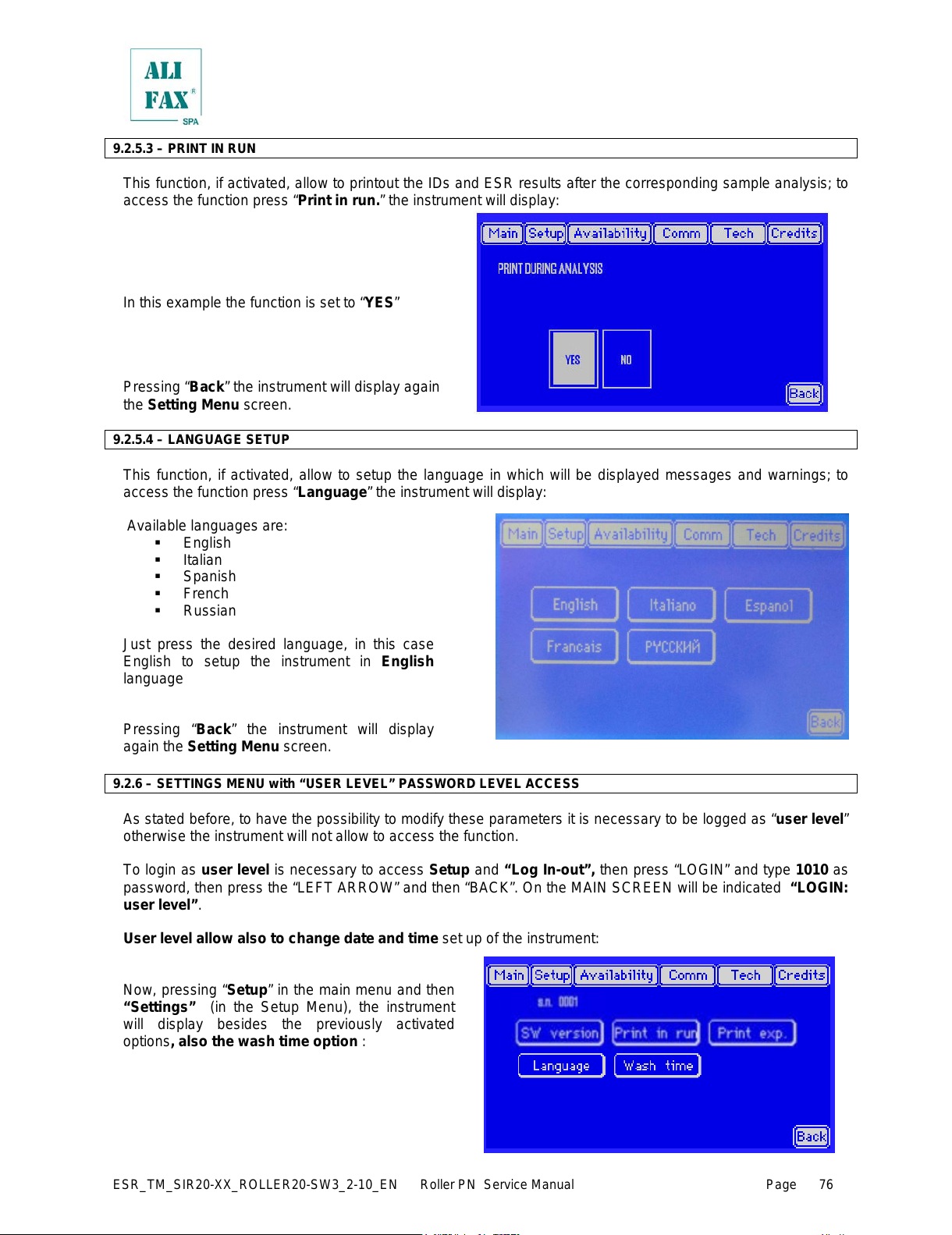
ESR_TM_SIR20-XX_ROLLER20-SW3_2-10_EN Roller PN Service Manual Page
76
9.2.5.3 – PRINT IN RUN
This function, if activated, allow to printout the IDs and ESR results after the corresponding sample analysis; to
access the function press “Print in run.” the instrument will display:
In this example the function is set to “YES”
Pressing “Back” the instrument will display again
the Setting Menu screen.
9.2.5.4 – LANGUAGE SETUP
This function, if activated, allow to setup the language in which will be displayed messages and warnings; to
access the function press “Language” the instrument will display:
Available languages are:
English
Italian
Spanish
French
Russian
Just press the desired language, in this case
English to setup the instrument in English
language
Pressing “Back” the instrument will display
again the Setting Menu screen.
9.2.6 – SETTINGS MENU with “USER LEVEL” PASSWORD LEVEL ACCESS
As stated before, to have the possibility to modify these parameters it is necessary to be logged as “user level”
otherwise the instrument will not allow to access the function.
To login as user level is necessary to access Setup and “Log In-out”, then press “LOGIN” and type 1010 as
password, then press the “LEFT ARROW” and then “BACK”. On the MAIN SCREEN will be indicated “LOGIN:
user level”.
User level allow also to change date and time set up of the instrument:
Now, pressing “Setup” in the main menu and then
“Settings” (in the Setup Menu), the instrument
will display besides the previously activated
options, also the wash time option :
All manuals and user guides at all-guides.com
Page 83

ESR_TM_SIR20-XX_ROLLER20-SW3_2-10_EN Roller PN Service Manual Page
77
9.2.6.1 – WASH TIME
This option allows to modify the delay of time (in minutes) for the alarm activation for a washing procedure
requesting. The counter’s countdown starts at the end of the analysis cycle.
To access this function, press “Wash Time” (in the Setup Menu), the instrument will display:
To modify the waiting time, just type the desired value
then press the “left arrow” to confirm or “Clear” to exit without change anything, the instrument will display
again the previous image. Pressing “Back” is possible to go back to MAIN SCREEN.
9.2.7 – SETTINGS MENU with “TECHNICAL LEVEL” PASSWORD LEVEL ACCESS
As stated before, to have the possibility to modify these parameters it is necessary to be logged as “technical
level” otherwise the instrument will not allow to access the whole functions.
To login is necessary to access (from Main Screen) to Setup
To access this function, press “Log In - Out” (in the Setup Menu), the instrument will display:
pressing “LOGIN” the instrument will display a keyboard, type 1990 as password, then press the “left arrow ”
to confirm or “Clear” to exit without change anything, in both cases, the instrument will display again the
previous image, then press “Back”.
All manuals and user guides at all-guides.com
Page 84

ESR_TM_SIR20-XX_ROLLER20-SW3_2-10_EN Roller PN Service Manual Page
78
Then, pressing “Settings” (in the Setup Menu), the instrument will display:
Buttons for changing page, from page 1 to page 2 (>>>>) and vice versa (<<<<).
As is possible see, the tech level password allow to access the previously explained functions (SW version, Print
in run, Print exp, Wash time, Reset Maint) plus others which will be explained in the next pages.
Remember that from software version 1.00N the control system has been changed, threshold is not more
necessary to set up a threshold level alarm for the waste tank because:
• at every switch ON of the instrument
• at every washing procedure start-up
• at the beginning of every cycle of analysis
the instrument controls the level of liquid inside the
waste tank, using the peristaltic pump to aspire
from the tank. If the pump aspires material, the
reading unit detects the presence of the material
and blocks the operation of the instrument,
informing via display that the waste tank needs to
be emptied/replaced.
9.2.7.1 – INSTRUMENT SERIAL NUMBER
This option allows to modify the Instrument’s Serial Number.
To access this function, press “s.n. XXXX” (in the Setup Menu), the instrument will display a keyboard allowing
to type the desired serial number:
then press the “left arrow” to confirm or “Clear” to exit without change anything, the instrument will display
again the previous image. Pressing “Back” is possible to go back to MAIN SCREEN.
TYPE SERIAL
NUMBER
(1 – 9999 )
All manuals and user guides at all-guides.com
Page 85

ESR_TM_SIR20-XX_ROLLER20-SW3_2-10_EN Roller PN Service Manual Page
79
9.2.7.2 – DEBUG
This function, if activated, allow the instrument to print out useful information for the technical service personnel.
This information can also be required by SIRE Foreign Technical Service in order to help local technical service
solve eventually problems with the instrument.
to activate the function press “Debug” the instrument will display.
In this example the function is set to “YES”. Pressing “Back” the instrument will display again the Setting Menu
screen
9.2.7.3 – CONFIGURATION OF KIND OF ROLLER (Available from software version 1.00N)
This function, allow the Technical Service Personnel to “configure” the installed software according with the kind
of Roller it will be used in.
The software installed and also eventually software upgrades are designed to be fully compatible with the 5
typologies of Roller available:
• Roller 10: the small one, with a capacity of 10 samples;
• Roller 10 PN: the same as Roller 10 plus the manual external withdrawal tip for pediatric test-tubes or for
test tubes without rubber cap;
• Roller 20 PN : with the capacity of 20 samples, equipped with an automatic washing system and manual
external withdrawal tip for pediatric test-tubes or for test tubes without rubber cap;
• Roller 20 WN: the same as Roller 20 PN, but only with the internal withdraw.
• Roller 20 MC: instrument only with manual external withdrawal without mixing (available soon, so don’t
use or select this type of Roller)
to activate the function press “Kind Of R.” the instrument will display:
Then pressing the appropriate button, software will activate the functionalities corresponding to each type of
instrument according to the option chosen.
Pressing “OK” the instrument will display again the Setting Menu screen
DEBUG
All manuals and user guides at all-guides.com
Page 86

ESR_TM_SIR20-XX_ROLLER20-SW3_2-10_EN Roller PN Service Manual Page
80
9.2.7.4 – MAINTENANCE LEVEL RESET
This function, if activated, allows TO CANCEL the maintenance counter. This counter increases every time an
analysis is executed.
When the threshold of maintenance is reached up (by default is set to 30000), the instrument will begin to
advise the necessity of technical maintenance.
If for some reason the maintenance is made before of the 30000 tests, pressing “Reset Maint.” The counter will
be set again to 0
Pressing “Back” the instrument will display again the Setting Menu screen
9.2.7.5 – MAINTENANCE LEVEL THRESHOLD SETUP
This function, if activated, allows setup the maintenance counter warning threshold at whose level the
instrument will require the maintenance service. The threshold is set by default to 30000 test.
Pressing “Maintenance” the instrument will display a keyboard allowing to type the desired threshold warning
level:
then press the “left arrow” to confirm or “Clear” to exit without change anything, the instrument will display
again the previous image. Pressing “Back” is possible to go back to MAIN SCREEN.
All manuals and user guides at all-guides.com
all-guides.com
Page 87
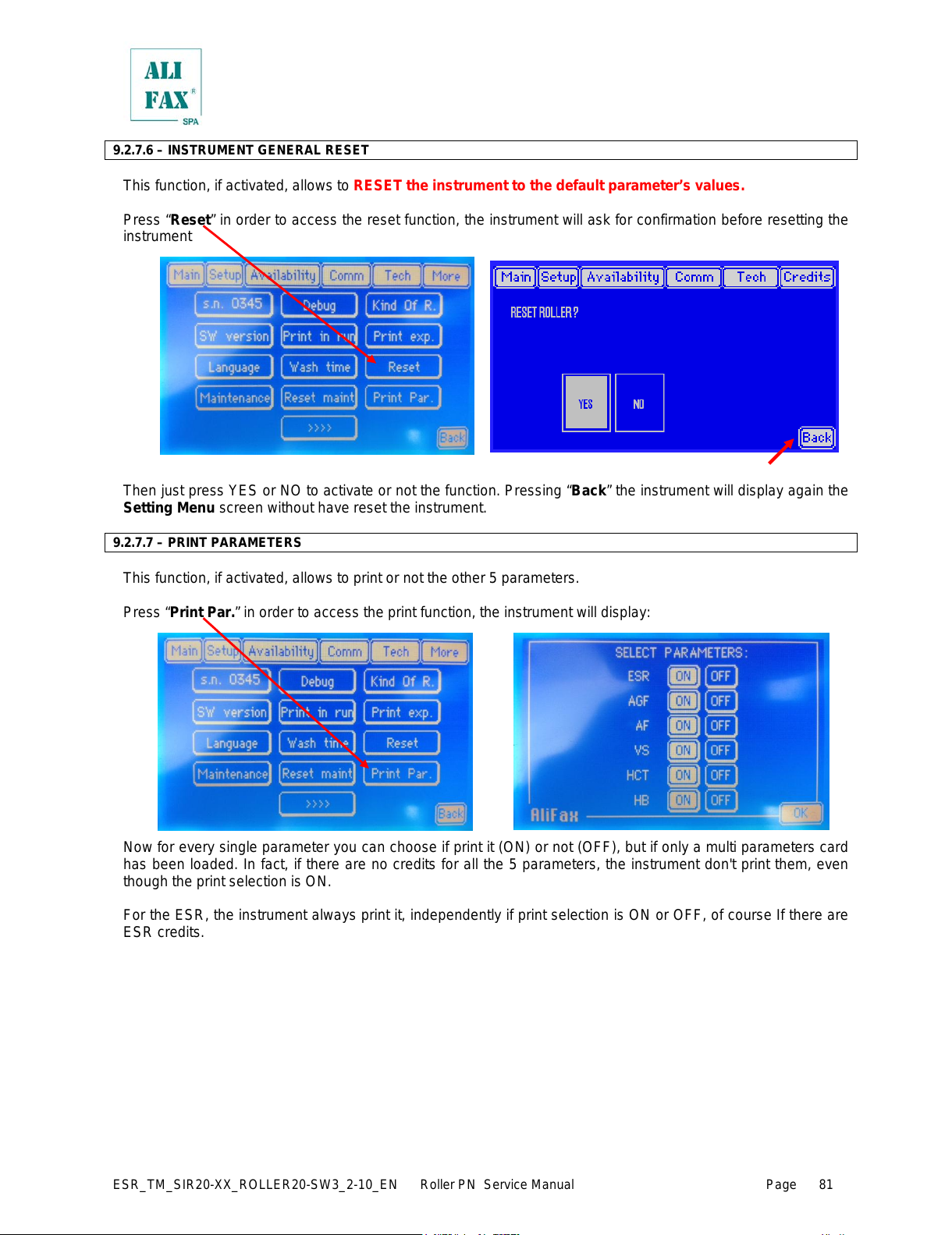
ESR_TM_SIR20-XX_ROLLER20-SW3_2-10_EN Roller PN Service Manual Page
81
9.2.7.6 – INSTRUMENT GENERAL RESET
This function, if activated, allows to RESET the instrument to the default parameter’s values.
Press “Reset” in order to access the reset function, the instrument will ask for confirmation before resetting the
instrument
Then just press YES or NO to activate or not the function. Pressing “Back” the instrument will display again the
Setting Menu screen without have reset the instrument.
9.2.7.7 – PRINT PARAMETERS
This function, if activated, allows to print or not the other 5 parameters.
Press “Print Par.” in order to access the print function, the instrument will display:
Now for every single parameter you can choose if print it (ON) or not (OFF), but if only a multi parameters card
has been loaded. In fact, if there are no credits for all the 5 parameters, the instrument don't print them, even
though the print selection is ON.
For the ESR, the instrument always print it, independently if print selection is ON or OFF, of course If there are
ESR credits.
All manuals and user guides at all-guides.com
Page 88
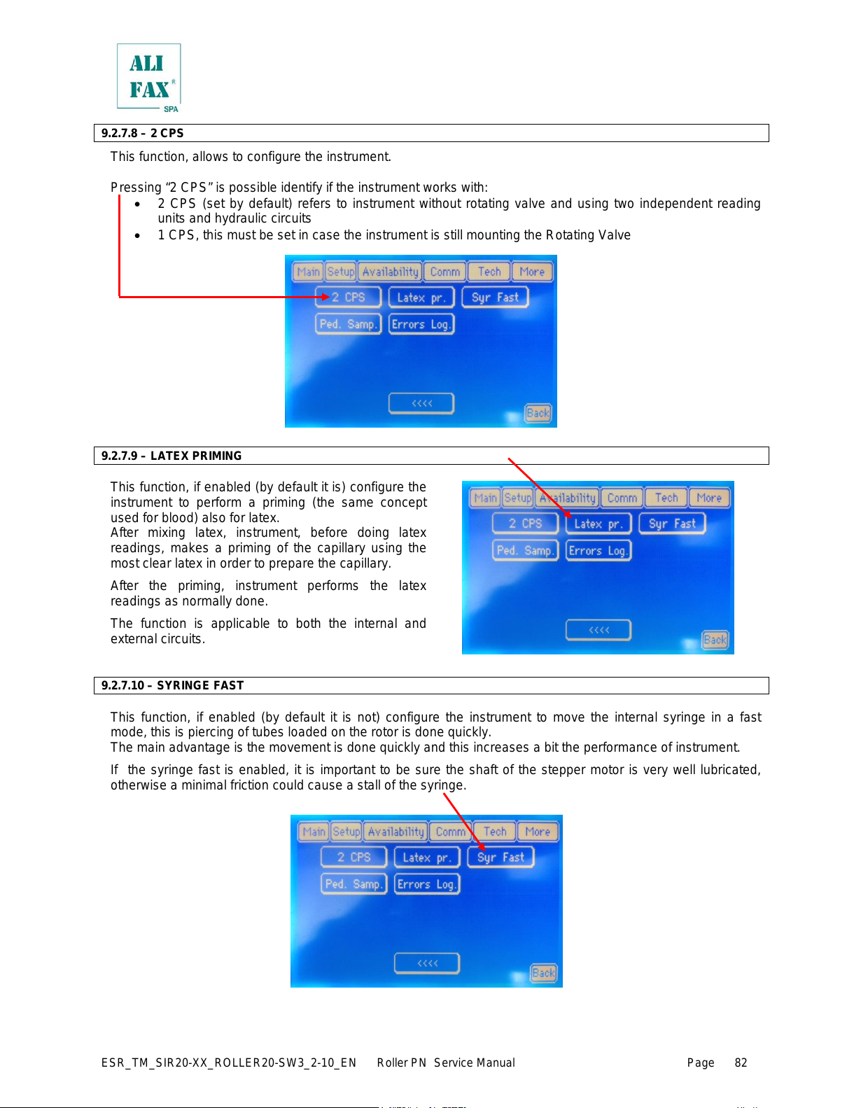
ESR_TM_SIR20-XX_ROLLER20-SW3_2-10_EN Roller PN Service Manual Page
82
9.2.7.8 – 2 CPS
This function, allows to configure the instrument.
Pressing “2 CPS” is possible identify if the instrument works with:
• 2 CPS (set by default) refers to instrument without rotating valve and using two independent reading
units and hydraulic circuits
• 1 CPS, this must be set in case the instrument is still mounting the Rotating Valve
9.2.7.9 – LATEX PRIMING
This function, if enabled (by default it is) configure the
instrument to perform a priming (the same concept
used for blood) also for latex.
After mixing latex, instrument, before doing latex
readings, makes a priming of the capillary using the
most clear latex in order to prepare the capillary.
After the priming, instrument performs the latex
readings as normally done.
The function is applicable to both the internal and
external circuits.
9.2.7.10 – SYRINGE FAST
This function, if enabled (by default it is not) configure the instrument to move the internal syringe in a fast
mode, this is piercing of tubes loaded on the rotor is done quickly.
The main advantage is the movement is done quickly and this increases a bit the performance of instrument .
If the syringe fast is enabled, it is important to be sure the shaft of the stepper motor is very well lubricated,
otherwise a minimal friction could cause a stall of the syringe.
All manuals and user guides at all-guides.com
Page 89

ESR_TM_SIR20-XX_ROLLER20-SW3_2-10_EN Roller PN Service Manual Page
83
9.2.7.11 – PEDIATRIC SAMPLES
This function, if enabled (by default it is not) configure the instrument to permit it to analyse also the pediatric
samples. In this mode, instrument rotor mix the sample with a special function, called centrifugation, that is
much powerful and fast than normal mixing. But remember this type of mixing must be used only with pediatric
samples, not with normal samples!
9.2.7.12 – ERROR LOG
This function, if activated, allows to see and print the mechanical and analytical errors.
Press “Errors Log.” in order to access the errors log, the instrument will display:
The screen show all the errors, and relative counters, only if the single error occurred in the instrument,
otherwise this is invisible until it occurs.
You can Print the Errors Log, pressing “Print” button, and also delete them pressing “Delete” and when the
instrument ask you to confirm, if you press “Yes” the function erases all the data, instead if you press “No” the
instrument come back to Setup menu.
Example of printout errors log:
All manuals and user guides at all-guides.com
Page 90

ESR_TM_SIR20-XX_ROLLER20-SW3_2-10_EN Roller PN Service Manual Page
84
9.2.8 – LOG IN-OUT
As stated before, the user will be required to type in a password to rise up from the 2
nd
to the 3rd level of the
instrument’s setup, otherwise the instrument will not allow to access the whole functions.
To login is necessary to access (from Main Screen) to Setup
To access this function, press “Log In - Out” (in the Setup Menu), the instrument will display:
pressing “LOGIN” the instrument will display a keyboard to type the password, type the proper password, then
press the “left arrow” to confirm or “Clear” to exit without change anything, in both cases, the instrument will
display again the previous image, then press “Back”.
To Logout, access this function, press “Log In - Out” (in the Setup Menu), press “LOGOUT” the instrument
will return to level 1. Pressing “Back” is possible to go back to MAIN SCREEN.
Password levels:
level
access
1 No password required, allow access only to the elementary functions
2
“LOGIN – USER LEVEL”:
allow access to the elementary setup functions. When the instrument is switched off, the instrument loose this
password, so next time the instrument is switched on it will be setup as level 1 (base level).
3
“LOGIN – TECH LEVEL”:
this level is only for Technical Service Personnel.
All manuals and user guides at all-guides.com
Page 91

ESR_TM_SIR20-XX_ROLLER20-SW3_2-10_EN Roller PN Service Manual Page
85
9.3 – AVAILABILITY MENU
Pressing “Availability” from the MAIN SCREEN, the instrument shows the following options
9.3.1 – WARNING LEVEL (User level password requi red)
To access this function it is necessary a password
Without a password
This function do not work without a password level and the instrument will display the following
message
As stated before, to activate this function it is necessary to be logged as “user level” or technical level
otherwise the instrument will not allow to access the function.
To login is necessary to access (from Main Screen) to Setup and the to “Log In-out”, then press “LOGIN” and
type 1010 as password (user level password) or 1990 as technical password, then pres s the “LEFT ARROW”
and then “Back”. On the MAIN MENU will be indicated the “LOGIN: user level”. Now is possible to access
“Availability” (from Main Screen) and then pressing “Warning level” the instrument will display the current
warning level and also the SET button.
Pressing SET the instrument allow to modify threshold level using the keyboard.
To increase availability type the desired warning value, then press the “Left Arrow” to confirm. The instrument
will display the previous image with the new warning reference; pressing “Back” it is possible to go back to
MAIN SCREEN.
All manuals and user guides at all-guides.com
all-guides.com
Page 92

ESR_TM_SIR20-XX_ROLLER20-SW3_2-10_EN Roller PN Service Manual Page
86
9.3.2 – DISPLAY AVAI LABILITY
To access this function it is NOT necessary a password
Pressing “Display Availability” the instrument will printout and display the current availability,
pressing “Back” it is possible to go back to MAIN SCREEN.
All manuals and user guides at all-guides.com
Page 93

ESR_TM_SIR20-XX_ROLLER20-SW3_2-10_EN Roller PN Service Manual Page
87
9.4 – COMM MENU (Technical password required)
Under this menu resides all the functions and options related with the communication between Roller 10 and a
Host Computer. To modify the whole parameters’ values is MANDATORY to login using the Technical
Service password (see chapter 9.2.7).
Without a password
This function do not work without a password level and the instrument will display the following
message
As stated before, to activate this function it is necessary to be logged as “tech level” otherwise the instrument
will not allow to access the function.
To login is necessary to access (from Main Screen) to Setup
To access this function, press “Log In - Out” (in the Setup Menu), the instrument will display:
pressing “LOGIN” the instrument will display a keyboard to type the password, type the password:1990 then
press the “left arrow” to confirm or “Clear” to exit without change anything, in both cases, the instrument will
display again the previous image, then press “Back”.
All manuals and user guides at all-guides.com
Page 94

ESR_TM_SIR20-XX_ROLLER20-SW3_2-10_EN Roller PN Service Manual Page
88
Now on MAIN MENU will be indicated the “LOGIN: tech level”. Then pressing “Setup” from Comm menu, the
instrument shows the following options
9.4.1 – SETUP MENU
After have pressed “Setup” the instrument will display:
9.4.1.1 – INSTRUMENT NUMBER
This option is useful to connect more instruments to the same PC Lab is for assigning a number to every
instrument between 01 to 09.
This number will be also reported in the Q and R strings of Query protocol.
Pressing “Str. n.” the instrument will display a keyboard, type the desired instrument number (for example
number 08), then press the “Left Arrow” to confirm or “Clear” to exit without change anything. The instrument will
display the previous image with the new instrument number displayed inside the corresponding button.
pressing “Back” it is possible to go back to MAIN SCREEN.
All manuals and user guides at all-guides.com
Page 95

ESR_TM_SIR20-XX_ROLLER20-SW3_2-10_EN Roller PN Service Manual Page
89
9.4.1.2 – TIMEOUT
This function (used only during the ESR result transmission to host) allows to increase the waiting time to get an
answer from Host computer. This option is useful if the instrument is connected to a network where the Host
computer (due to its working load) needs more than 2 seconds to answer a query.
The default value is 2 seconds, and the possible choice is between 0 to 60 seconds.
This function works if “ACK” flag has been activated, if not, timeout is 2 seconds which is the default
value.
Pressing “Timeout.” the instrument will display a keyboard, type the desired timeout waiting time (for example 05
seconds), then press the “Left Arrow” to confirm or “Clear” to exit without change anything. The instrument will
display the previous image with the new timeout number displayed inside the corresponding button;
pressing “Back” it is possible to go back to MAIN SCREEN.
9.4.1.3 – ATTEMPTS
This function allows to set the number of attempts (of timeout events) for:
• Query Host computer (Q message)
• Wait an answer from Host computer (T message)
• Refertation (wait an ACK from Host computer) after have sent the results (R message)
This function works according to the status of “Do on T. out” and “ACK” flags
• Q message: after “n” attempts (without getting an ACK from Host computer) the instrument will allow to
load the sample if “Do on T.out” flag is set to “Yes”, otherwise will deny the sample load.
• T message: after “n” attempts (without getting a T message from Host computer) the instrument will allow
to load the sample if “Do on T.out” flag is set to “Yes”, otherwise will deny the sample load
• R message: after “n” attempts (without getting a ACK that confirms the reception from Host computer) the
instrument will skip the transmission of that sample result, will only printout the result and will
proceed to analyse the next sample if “Do on T.out” flag is set to “Yes”, otherwise will deny
the sample load.
Pressing “Attempts.” the instrument will display a
keyboard, type the desired attempts, the possible choice
is between 0 and 99, (for example 10 attempts), then
press the “Left Arrow” to confirm or “Clear” to exit
without change anything.
The instrument will display the previous image with the
new attempts number displayed inside the corresponding
button;
Pressing “Back” it is possible to go back to MAIN SCREEN.
All manuals and user guides at all-guides.com
Page 96

ESR_TM_SIR20-XX_ROLLER20-SW3_2-10_EN Roller PN Service Manual Page
90
9.4.1.4 – MISSING ID
This function, if activated, allow analysis of samples that:
• Host doesn’t recognize (instrument receives a
NAK answer after a query)
• After the attempts trials has expired and the ID
number inside Q message do not match the ID
number inside T message
To access the function press “Missing ID” then, to
activate the function press “YES”, or to deactivate the
function, press “NO”; after that, pressing “Back” the
instrument will display again the Setup Menu screen.
9.4.1.5 – DO ON TIMEOUT UART
This function, if activated, allow analysis of samples if:
• The waiting time set on “Timeout” menu
(9.4.1.2.) has expired and Host computer hadn’t
send back a T message or a NAK message
during the timeout time.
To access the function press “Do on T.out” then, to
activate the function press “YES”, or to deactivate the
function, press “NO”; after that, pressing “Back” the
instrument will display again the Setup Menu screen.
9.4.1.6 – ACK
This function is directly related with “Timeout Uart” (9.4.1.2); if activated allows the TIMEOUT UART function to
extend the delay time for wait a “T” message (Query answer from the HOST computer) and ACK (acknowledge
message from HOST computer).
To access the function press “ACK” then, to activate the function press “YES”, or to deactivate the function,
press “NO”; after that, pressing “Back” the instrument will display again the Setup Menu screen.
All manuals and user guides at all-guides.com
all-guides.com
Page 97

ESR_TM_SIR20-XX_ROLLER20-SW3_2-10_EN Roller PN Service Manual Page
91
9.4.1.7 – BAYER (only with BCI interface)
The function is used in “R” message to grant the Bayer protocol compatibility. This option is used if Host
computer handles Bayer DAT protocols.
• If Bayer is enabled (default), the instrument uses
the Bayer DAT protocol directives.
• If Bayer is disabled, the instrument uses the
modified DAT protocol
Bayer communication protocol detects the Bayer field
value (the field before the ESR result) in the “R”
message. If Bayer function is enabled, the field will
contain '01' (hex 30 and 31) to maintain the Bayer
protocol compatibility otherwise if it is disabled, the field
will report the number of Cycle.
To access the function press “Bayer” then, to activate the function press “YES”, or to deactivate the function,
press “NO”; after that, pressing “Back” the instrument will display again the Setup Menu screen.
9.4.1.8 – 6 Parameters Transmission (under development).
The function is used to send additional results to host computer. Roller family instruments are able to analyse
blood and in addition to ESR determine also other 5 parameters. Depending how many of this parameters has
been activated (using a specific smart card), the instrument will send results to host computer.
• If “Send 6 par” is disabled (default), the instrument
sends only ESR result to host computer.
• If “Send 6 par” is enabled, the instrument sends
also the results of the other activated parameters.
To access the function press “Send 6 Par” then, to
activate the function press “YES”, or to deactivate the
function, press “NO”; after that, pressing “Back” the
instrument will display again the Setup Menu screen.
NOTE: at the moment it is not suggest to activate 6 parameters transmission to host computer because
Host protocol is not designed to receive all 6 parameters, only E S R.
9.4.1.9 – Curve Parameters Transmission (under development).
The function is used to send additional results to host computer. Roller family instruments are able to send the
parameters of the blood curve to host computer.
• If “Curve Par” is disabled (default), the instrument
sends only ESR result to host computer.
• If “Curve Parr” is enabled, the instrument sends
also the blood curve parameters.
To access the function press “Curve Par” then, to
activate the function press “YES”, or to deactivate the
function, press “NO”; after that, pressing “Back” the
instrument will display again the Setup Menu screen.
NOTE: at the moment it is not suggest to activate
curve parameters transmission to host computer
because Host protocol is not designed to receive them.
All manuals and user guides at all-guides.com
Page 98

ESR_TM_SIR20-XX_ROLLER20-SW3_2-10_EN Roller PN Service Manual Page
92
9.4.1.10 – PROTOCOL INTERFACE OPTIONS
In the lower part of the Communication Setup configuration screen is possible to choose the protocol to be used
to communicate between the Roller 10 and the Host computer. The instrument offers 4 choices:
PORT2 connection.
SERIAL CABLE PIN CONNECTIONS TO CONNECT ROLLER10PN/20PN TO PC-LAB:
DB9 F DB9 F
1 1
2 2
3 3
4 4
5 5
6 6
7 7
8 8
9 9
Interface protocol uses the following parameter:
Speed: 9600
Length: 8 bit
Parity: N
Stop: 1 bit
The instrument communicates through Serial Port 1.Thi s port
uses a 9 pin male (DB9) serial connector.
The used pins are: n° 2 for TXDATA, n° 3 for RXDATA and 7
for ground. The remaining pins are connected together as null-
modem configuration.
This cable must have a D-type 9 pin female connector from
one side and a D-type 9 pin female connector at the opposite
side.
All manuals and user guides at all-guides.com
Page 99

ESR_TM_SIR20-XX_ROLLER20-SW3_2-10_EN Roller PN Service Manual Page
93
9.4.1.10.a – DAT 8 INTERFACE (NO QUERY)
Pressing “DAT 8 button, the instrument will highlight and activate this option as communi cat i on prot ocol
DAT8 transmission and its examination:
Field name
Symbol
Hex
value
Length
Description
Note1:
Checksum value is the result of
Exclusive OR (XOR) of all
characters of the message,
excluded STX, ETX and
Checksum. If the Checksum value
calculated by the analyzer is 03
(corresponding to ETX), or 02
(correspon
ding to STX), or 00
(corresponding to NULL), the
value will be automatically
replaced with 7F hex value.
Software House must adopt the
same procedure when
calculating checksum of the
strings received from the
analyzer.
Note2: Bayer field not used, in this
case show s the progressive
analysis cycle
STX
☻
02 1 char
Start transmission
‘R’ 52
1 char
R states for result message
Workstation
Number
2 char
Is the number identifying the instrument if more than
one is connected to Host computer
Patient ID
Number
8 char
Patient identification
Wheel no.
2 char
Indicate the progressive number of analysis made
Position
2 char
Indicate the sample position inside the wheel
Bayer
(Note 2)
2 char
See note 2
Result
4 char
ESR result
Checksum
(Note 1)
1 char
See note 1
ETX
♥
03 1 char End transmission
Total length
24 char
PROTOCOL
Query
DESCRIPTION
R message structure
SYMBOLS
NOTES
DAT8
No
Used to read the
maximum patient
identity length of
8 characters by
an external bar
code reader
(EBCR) It can be
also used to
insert patient IDs
manually.
STX 1 byte
R 1 byte
Not used 2 byte
Identification no 8 byte
Not used 6 byte
ESR result 4 byte
Checksum 1 byte
ETX 1 byte
TOTAL = 24 byte
☻
♥
Checksum note
Checksum value is the result of
Exclusive OR (XOR) of all
characters of the message,
excluded STX, ETX and
Checksum. If the Checksum value
calculated by the analyzer is 03
(corresponding to ETX), or 02
(corresponding to STX), or 00
(
corresponding to NULL), the
value will be automatically
replaced with 7F hex value.
Software House must adopt the
same procedure when
calculating checksum of the
strings received from the
analyzer.
All manuals and user guides at all-guides.com
Page 100

ESR_TM_SIR20-XX_ROLLER20-SW3_2-10_EN Roller PN Service Manual Page
94
9.4.1.10.b – DAT 15 INTERFACE (NO QUERY)
Pressing “DAT 15” button, the instrument will highlight and activate this option as communicati on protocol
DAT15 transmission and its examination:
Field name
Symbol
Hex
value
Length
Description
Note1:
Checksum value is the result of
Excl
usive OR (XOR) of all
characters of the message,
excluded STX, ETX and
Checksum. If the Checksum value
calculated by the analyzer is 03
(corresponding to ETX), or 02
(corresponding to STX), or 00
(corresponding to NULL), the
value will be automatically
replaced with 7F hex value.
Software House must adopt the
same procedure when
calculating checksum of the
strings received from the
analyzer.
Note2
:see previous table
STX
☻
02 1 char
Start transmission
‘R’
52
1 char
R states for result message
Workstation
Number
2 char
Is the number identifying the instrument if more than
one is connected to Host computer
Patient ID
Number
15 char
Patient identification
Rack no.
2 char
Indicate the progressive number of analysis made
Position
2 char
Indicate the sample position inside the wheel
Bayer
(Note 2)
2 char
See
note 2
Result
4 char
ESR result
Checksum
(Note 1)
1 char
See note 1
ETX
♥
03 1 char End transmission
Total length
31 char
PROTOCOL
Query
DESCRIPTION
R message structure
SYMBOLS
NOTES
DAT15
No
Used to read
the maximum
patient identity
length of 15
characters by
an external bar
code reader
(EBCR).
STX 1 byte
R 1 byte
Workstation number 2 byte
Identification n 15 byte
Rack number 2 byte
Position 2 byte
Cycle/Bayer 2 byte
ESR result 4 byte
Checksum 1 byte
ETX 1 byte
TOTAL = 31 byte
☻
♥
Note1:
Checksum value is the result of
Exclusive OR (XOR) of all
characters of the message,
excluded STX, ETX and
Checksum. If the Checksum value
calculated by the analyzer is 03
(corresponding to ETX), or 02
(corresponding to STX), or 00
(cor
responding to NULL), the
value will be automatically
replaced with 7F hex value.
Software House must adopt the
same procedure when
calculating checksum of the
strings received from the
analyzer.
Note2
: If Bayer is NO, the field deals
with the number of Cycle otherwise
if Bayer is YES, the field will
contain '01' (hex 30 and 31) to
maintain the Bayer protocol
compatibility.
All manuals and user guides at all-guides.com
 Loading...