

Page 1
23456789012345678901
2
2
2
2
2
2
2
2
2
2
2
2
2
2
2
2
2
2
2
2
2
2
2
2
2
2
2
2
2
2
2
2
2
2
2
2
2
2
2
2
2
2
2
2
2
2
2
2
2
2
2
2
2
2
2
2
2
2
2
2
2
2
2
2
2
2
2
2
2
2
2
2
2
2
2
2
2
2
2
2
2
2
2
2
2
2
2
2
2
2
2
2
2
2
2
2
2
2
2
2
2
2
2
2
2
2
2
2
2
2
2
2
2
2
2
2
2
2
2
2
2
2
2
2
2
2
2
2
2
2
2
2
2
2
2
2
2
23456789012345678901
23456789012345678901
23456789012345678901
23456789012345678901
23456789012345678901
23456789012345678901
23456789012345678901
23456789012345678901
23456789012345678901
23456789012345678901
23456789012345678901
23456789012345678901
23456789012345678901
23456789012345678901
23456789012345678901
23456789012345678901
23456789012345678901
23456789012345678901
23456789012345678901
23456789012345678901
23456789012345678901
23456789012345678901
23456789012345678901
23456789012345678901
23456789012345678901
23456789012345678901
23456789012345678901
23456789012345678901
23456789012345678901
23456789012345678901
23456789012345678901
23456789012345678901
23456789012345678901
23456789012345678901
23456789012345678901
23456789012345678901
23456789012345678901
23456789012345678901
23456789012345678901
23456789012345678901
23456789012345678901
23456789012345678901
23456789012345678901
23456789012345678901
23456789012345678901
23456789012345678901
23456789012345678901
23456789012345678901
23456789012345678901
23456789012345678901
23456789012345678901
23456789012345678901
23456789012345678901
23456789012345678901
23456789012345678901
23456789012345678901
23456789012345678901
23456789012345678901
23456789012345678901
23456789012345678901
23456789012345678901
23456789012345678901
23456789012345678901
23456789012345678901
23456789012345678901
23456789012345678901
23456789012345678901
23456789012345678901
23456789012345678901
23456789012345678901
23456789012345678901
23456789012345678901
23456789012345678901
23456789012345678901
23456789012345678901
23456789012345678901
23456789012345678901
23456789012345678901
23456789012345678901
23456789012345678901
23456789012345678901
23456789012345678901
23456789012345678901
23456789012345678901
23456789012345678901
23456789012345678901
23456789012345678901
23456789012345678901
23456789012345678901
23456789012345678901
23456789012345678901
23456789012345678901
23456789012345678901
23456789012345678901
23456789012345678901
23456789012345678901
23456789012345678901
23456789012345678901
23456789012345678901
23456789012345678901
23456789012345678901
23456789012345678901
23456789012345678901
23456789012345678901
23456789012345678901
23456789012345678901
23456789012345678901
23456789012345678901
23456789012345678901
23456789012345678901
23456789012345678901
23456789012345678901
23456789012345678901
23456789012345678901
23456789012345678901
23456789012345678901
23456789012345678901
23456789012345678901
23456789012345678901
23456789012345678901
23456789012345678901
23456789012345678901
23456789012345678901
23456789012345678901
23456789012345678901
23456789012345678901
23456789012345678901
23456789012345678901
23456789012345678901
23456789012345678901
23456789012345678901
23456789012345678901
23456789012345678901
23456789012345678901
23456789012345678901
23456789012345678901
IPSO - LSG n.v.
Instruction manual
WE 55, WE 73, WE 95
WE 110, WE 132, WE 165
Technical specifications
Installation instructions
Operating instructions
Maintenance
Nieuwstraat 146 - B-8560 Wevelgem (Belgium)
Tel. 056/41 20 54 - Fax 056/41 86 74
Page 2

Contents
1 General safety instructions .............................................................. 3
2 Technical data and dimensions ....................................................... 4
Technical data ................................................................................ 4
Dimensions ..................................................................................... 6
3 Installation and connection ............................................................. 8
Ground ............................................................................................ 8
Anchoring ....................................................................................... 8
Water connection ............................................................................ 8
Water drain ..................................................................................... 9
Main power connection .................................................................... 9
Steam connection ........................................................................... 10
4 Operating instructions ..................................................................... 11
Machine with CAM-timer and 10 buttons ......................................... 11
Machine with CAM-timer and coin meter .......................................... 14
Machine with electronical PLC-9 microprocessor and start button ... 16
5 Technical remarks ............................................................................ 20
Program time (Machine with CAM-timer) .......................................... 20
Internal connection of the electrical heating .................................... 21
Internal connections of the motor .................................................... 21
Thermo-magnetic motor protection .................................................. 22
Installation of the electronic stepper................................................ 22
6 Maintenance of the machine ........................................................... 24
Code: 249/00003/03
16/09/97
Contents
Page 3
General safety instructions
Ignoring any of the safety instructions can cause serious personal injury and can also cause damage to the linen or the
machine
Read the installation and instruction manual carefully before connecting the
p
machine.
It is recommended that the machine be installed by qualified technicians.
p
The machine should be installed according to the installation instructions. (See
p
chapter 4)
The machine should be grounded according to the instructions in order to
p
eliminate the risk of electrocution.
Do not expose the machine to high humidity or extreme high or low tempera-
p
tures.
Cut off all main water inlets, steam and electrical supplies at the end of each
p
operating day.
1
Before starting repairs or maintenance, shut off all power and water supplies.
p
To prevent fire and explosion:
p
Keep the area around the machine free from inflammable or combustible
products.
Do not put fabrics that are treated with inflammable products into the machine.
These fabrics should be hand-washed or air-dried first.
Always carefully read and follow the instructions on the packing of detergents.
p
Store these products out of the reach of children.
Always take into account the instructions on the labels of clothes.
p
Never allow children to play in the surroundings of a machine.
p
Remark:
These instructions surely cannot prevent all risks of accidents. It is up to the user to act with the utmost
p
precaution.
Do not hesitate to contact the dealer in case of a problem.
p
3
Page 4

Technical data and dimensions
Technical data
Capacity (dry weight)
1/11 5 kg 6,6 kg 8,6 kg
1/10 5,5 kg 7,3 kg 9,5 kg
1/9 6,1 kg 8,1 kg 10,5 kg
Cylinder
Diameter 530 mm 530 mm 530 mm
Depth 295 mm 345 mm 440 mm
Volume 55 Lit. 73 Lit. 95 Lit.
Cabinet
Height 1005 mm 1005 mm 1110 mm
Width 660 mm 660 mm 660 mm
Depth 670 mm 670 mm 770 mm
Front loading
Diameter door opening 300 mm 300 mm 300 mm
Door height 360 mm 360 mm 455 mm
To center 510 mm 510 mm 605 mm
Speed
Wash 50 rpm
Spin 500 rpm
G-force
Spin 74
Motor(3 phase)
Wash 18p. 290rpm 120 W 120 W 120 W
Spin 2p. 2900 rpm 370 W 370 W 550 W
Drain valve
Depend-O-Drain 6/4"
Water supply
Hard, soft, warm water and cool-down 3/4"
Steam connection
Steam connection 3/8"
Heating
Electrical 220/380 V 4,2/6/9 kw
Electrical 380 V 12 kw
Steam X
Warm water (without additional heating) X
Warm water (with additional heating) X
Packing dimensions
(H x W x D) 1140x732x832mm (WE55/73/95)
1230x732x950mm (WE95)
Weight
N et 16 5 k g 1 70 kg 17 8 k g
Gross 220 kg 225 kg 230 kg
2
WE 55 WE 73 WE 95
4
Page 5

Capacity (dry weight)
Cylinder
Cabinet
Front loading
Speed
G-force
Motor(3 phase)
Drain valve
Water supply
Steam connection
Heating
Packing dimensions
Weight
2
WE 110 WE 132 WE 165
1/11 10 kg 12 kg 15 kg
1/10 11 kg 13,2 kg 16,5 kg
1/9 12,2 kg 14,5 kg 18,3 kg
Diameter 650 mm 650 mm 650 mm
Depth 330 mm 400 mm 500 mm
Volume 110 Lit. 132 Lit. 165 Lit.
Height 1170 mm 1170 mm 1170 mm
Width 780 mm 780 mm 780 mm
Depth 760 mm 760 mm 860 mm
Diameter door opening 300 mm 300 mm 300 mm
Door height 465 mm 465 mm 465 mm
To center 615 mm 615 mm 615 mm
Wash 50 rpm
Spin 500 rpm
Spin 88
Wash 18p. 290rpm 220 W 220 W 280 W
Spin 2p. 2900 rpm 1100 W 1100 W 1300 W
Depend-O-Drain 6/4"
Hard, soft, warm water and cool-down 3/4"
Steam connection 3/8"
Electrical 220/380 V 12/15/18 kw
Electrical 380 V 21/24 kw
Steam X
Warm water (without additional heating) X
Warm water (with additional heating) X
(H x W x D) 1310x850x922mm (WE110/132)
1310x850x1022mm (WE165)
Net 230 kg 235 kg 245 kg
Gross 285 kg 290 kg 315 kg
5
Page 6
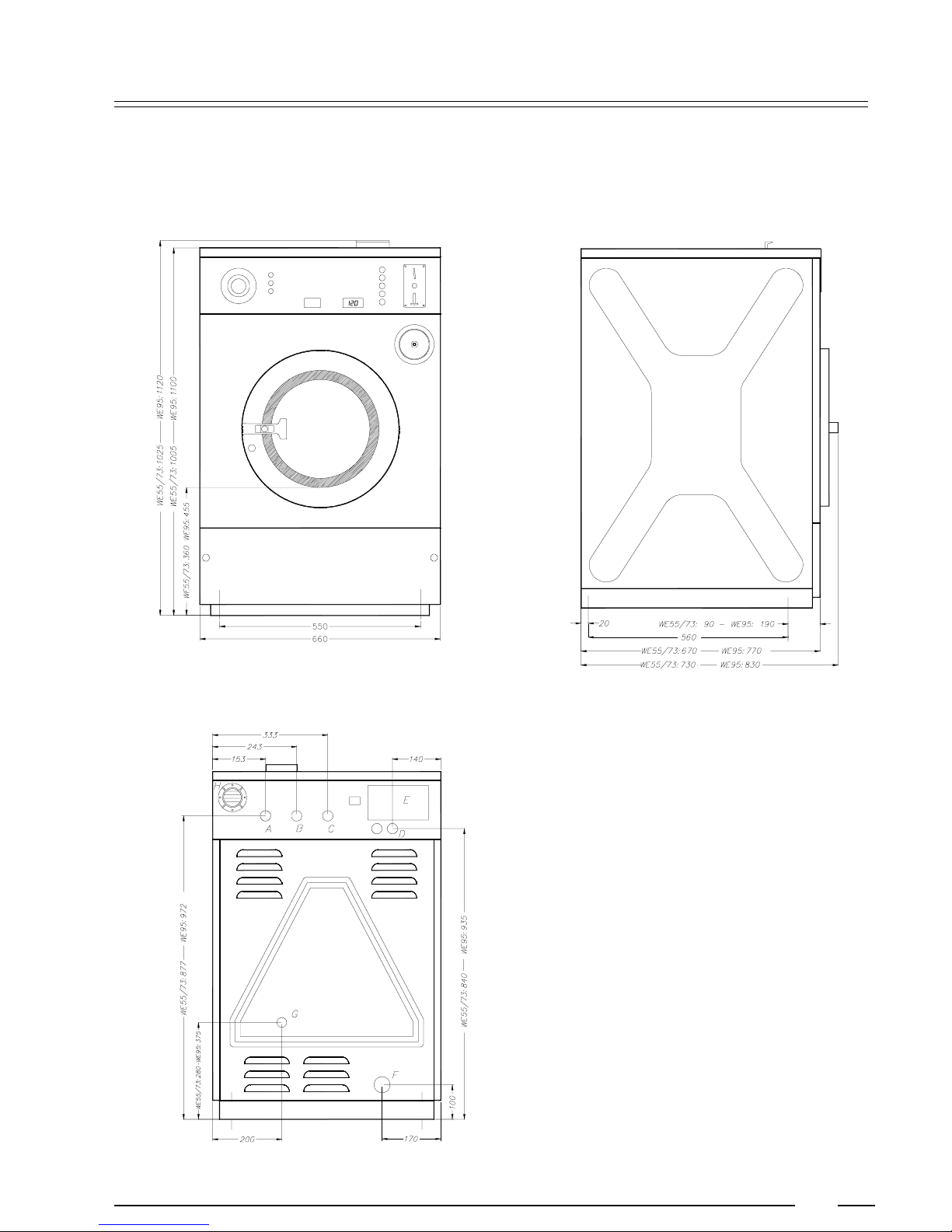
Dimensions
WE55/73/95
2
A. Hard water connection 3/4"
p
B. Warm water connection 3/4"
p
C. Soft water connection 3/4"
p
D. Electrical connection
p
E. Electrical connection clamps
p
F. Water drain
p
G. Steam connection
p
H. Ventilation soap dispenser
p
6
Page 7
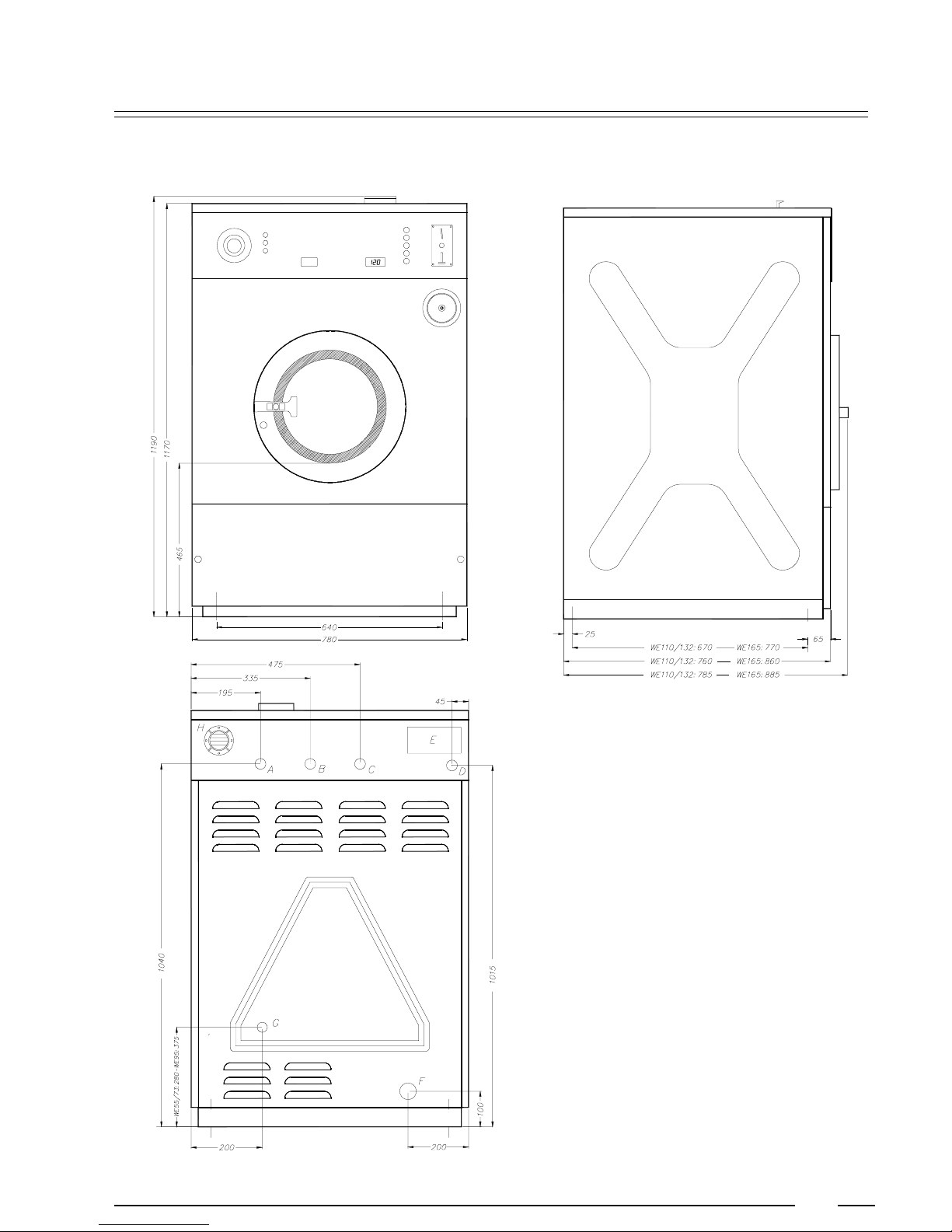
WE110/132/165
2
A. Hard water connection 3/4"
p
B. Warm water connection 3/4"
p
C. Soft water connection 3/4"
p
D. Electrical connection
p
E. Electrical connection clamps
p
F. Water drain
p
G. Steam connection
p
H. Ventilation soap dispenser
p
7
Page 8
Installation and connection
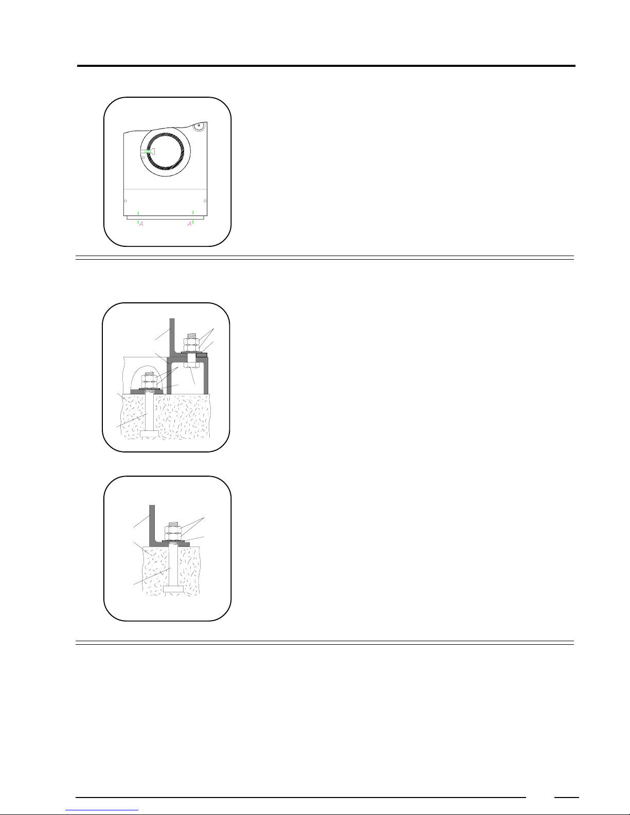
Surface
The machine must be securely fixed on a flat surface (metal base, concrete or solid
ground). The anchoring is to be done on the provided places (A) in the base. (See
Dimensions 2)
The machine must be placed entirely level. For easy maintenance it is recommended to keep a minimal distance of 600 mm between the wall and the back of the
machine.
If several machines are placed next to each another, there should be a minimal
distance of 30 mm between each machine.
Anchoring
On a metal base
D
E
F
D
B
A
CG
C
The machines must be fixed on a metal base which is securely anchored on a
concrete base.
A: Bolt M12 (WE55/73/95), M16 (WE110/132/165)
B: Concrete base (WE55/73: 20cm, WE95/110: 30cm, WE132/165: 40cm)
C: Washer 40x17x4
D: Nut M12 (WE55/73/95), M16 (WE110/132/165)
E: Base of the machine
F: Metal base
3
E
B
A
Water connection
Directly on the ground
D
C
The machine must be anchored directly on a concrete base.
A: Bolt M12 (WE55/73/95), M16 (WE110/132/165)
B: Concrete base (WE55/73: 20cm, WE95/110: 30cm, WE132/165: 40cm)
C: Washer 40x17x4
D: Nut M12 (WE55/73/95), M16 (WE110/132/165)
E: Base of the machine
The machine is delivered with hoses with 3/4" connections. These hoses fit the
water inlet valves of the machine and the main water inlet taps. To ensure the
optimal functioning of the water inlet valves, the water pressure on the inlet should
be between 0,5 and 10 kg/cm² (7 and 145 psi). If the pressure is too low, the cycle
time will increase considerably.
In case of boiler fed machines, a minimum of hot water of 90°C should be available:
For the WE55: 50 l. WE 110: 90l.
For the WE73: 65 l. W E 132: 120l.
For the WE95: 80 l. W E 165: 140l.
8
Page 9
3
Water drain
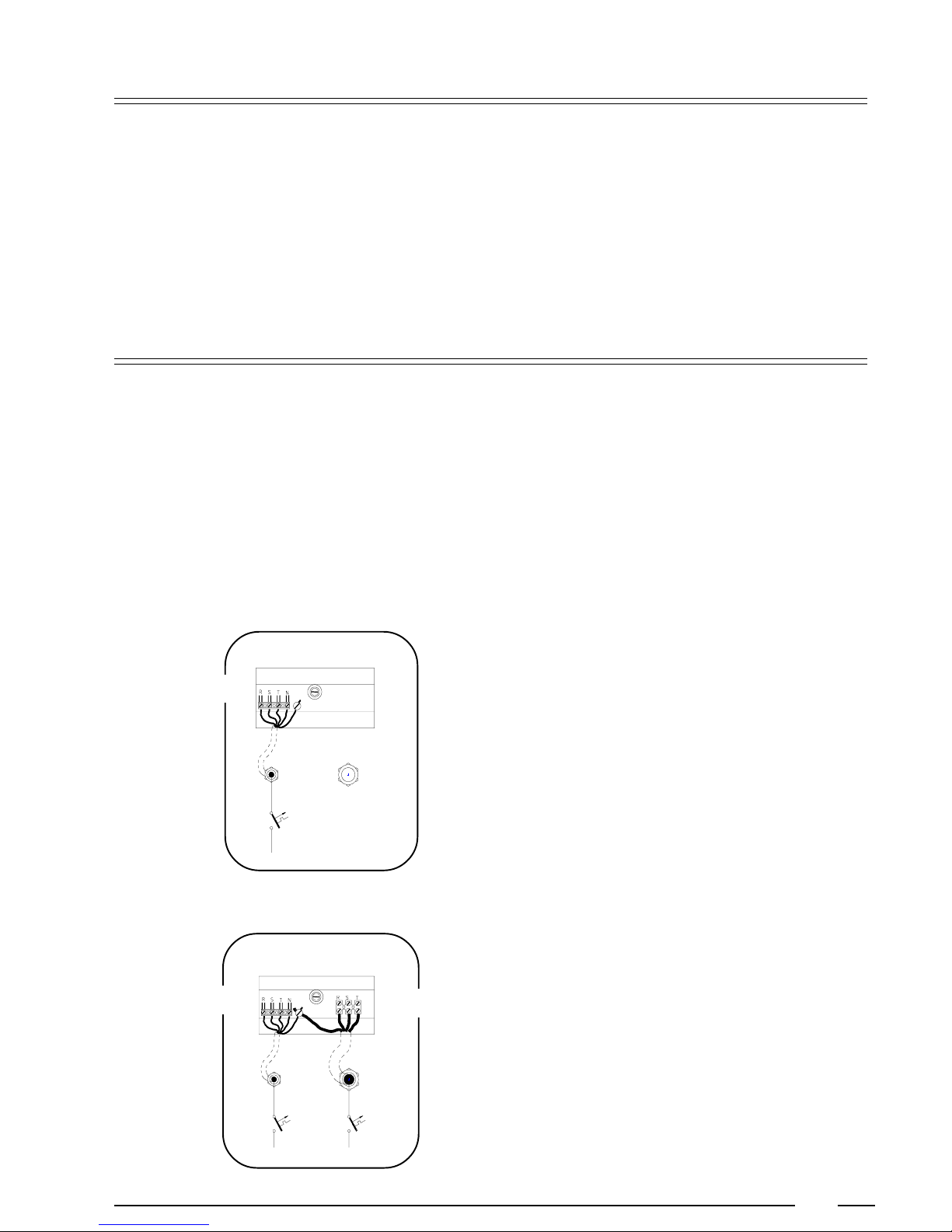
Main power connection
The machine is equipped with a drain valve with 6/4" outer diameter (50 mm).
This drain valve should be connected to the drain by means of the drain
elbow which is delivered with the machine.
The diameter of the main drain should be adapted to the water flow and
p
the number of machines. It should be sufficient to handle at least 80L/min.
per machine.
It is necessary to connect the main drain at least on one side to an open
p
air-brake to allow ventilation.
When the main drain has not been sufficiently deodorized, every
p
machine should be installed seperately with a deodorizer.
In case of machines with electrical heating two seperate connections
p
should always be used. One for the motor circuit, one for the heating.
After connection, check the spin direction. The cylinder must spin in the
p
direction of the arrow, showed on the sticker on the door window
(clockwise).
A wrong spin direction can damage the motor, and can also cause water
to spurt from the soap dispenser.
In case of wrong spin direction: switch the terminal clamps of the motor
p
circuit R and S of the connecting cable.
Motor
Motor
Heating
Machine with steam heating or boiler fed
machine without additional electrical heating
Value of mains fuses:
Motor circuit: 220V 3AC 380V 3AC + N
16A 16A
Machine with electrical heating
Value of the mains fuses:
Motor circuit: 220V 3AC 380V 3AC + N
16A 16A
Heating:220V 3AC380V 3AC + N
4,2 kw 16A 16A
6 kw 16A 16A
9kw 25A 16A
12kw ---- 25A
15 kw 50A 25 A
18 kw 50 A 32 A
21 kw ---- 40 A
24 kw ---- 40 A
9
Page 10
3
Steam connection
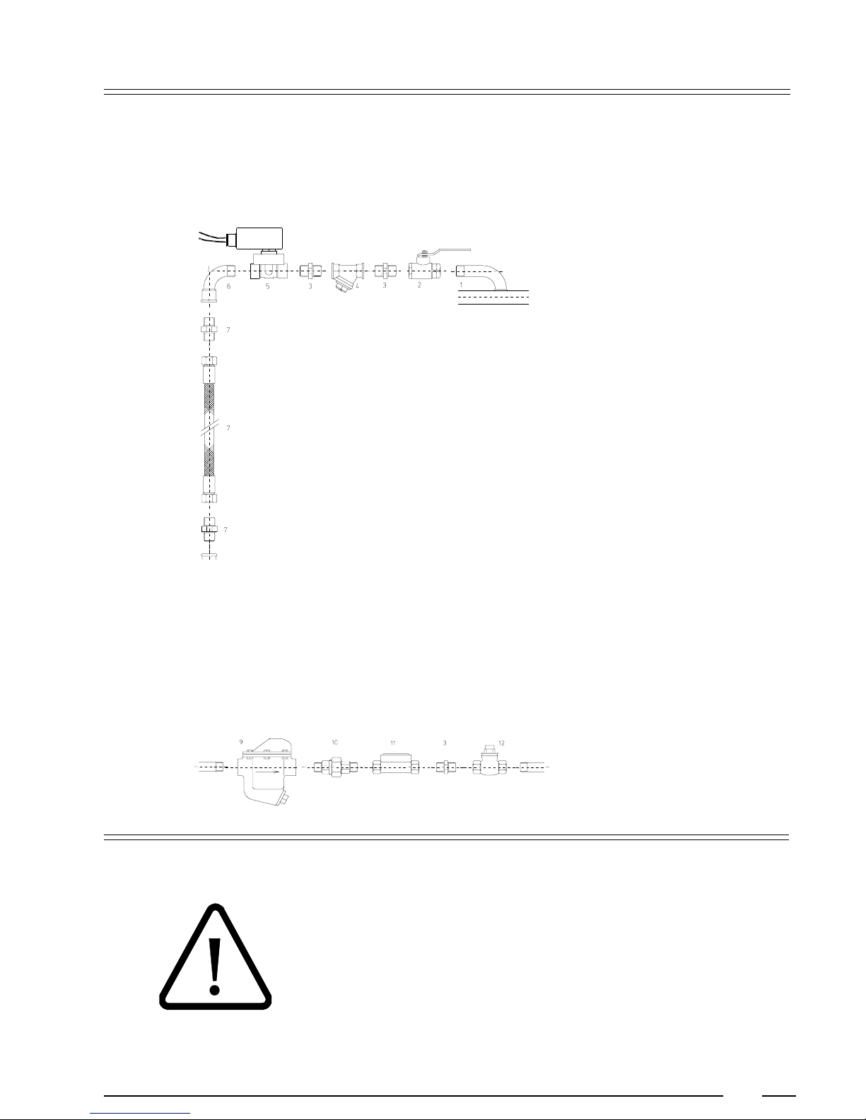
Machines with steam heating must have a steam valve between the steam
installation and the machine.
With direct steam injection into the machine
1. Steam pipe
2. steam cut-off valve 3/8"
3. Pipe coupling 3/8"
4. Steam filter 3/8"
5. Magnetic steam valve 3/8"
6. Curve MF 3/8"
7. Steam hose with appropriate pipe coupling 3/8"
Added parts for steam heating with heat exchanger
3. Double pipe coupling 1/2"
9. Condensation accumulator with filter 1/2"
10. Conical coupling MM 1/2"
11. Single window 1/2"
12. One-way valve 1/2"
M = inner wire, F = outer wire
The manufacturer is not responsible for damage or accidents caused by not following the installation instructions!
10
Page 11
Operating instructions
Machine with CAM-timer and 10 buttons
4
Open the door
Fill the drum
Close the door
Select program
Press the red button on the doorhandle and open the door.
The machines have 5 wash programs. Sort the linen according to the quality and
the allowed wash temperature. Remove all nails, coins, etc. that can damage the
linen or the machine during the wash cycle. Turn sleeves of overcoats, shirts and
blouses inside out. To increase the wash action and thus the quality of the wash,
it is recommended to mix large and small pieces.
If the machine is filled less than 80% of the capacity, this could prevent a good
operation and can even damage the machine.
Overloading the machine can be the cause of low wash quality.
Press the button of the desired program: (1-5)
1. Hot wash (2 baths)(40°/90°C)
2. Warm wash (2 baths)(40°/60°C)
3. Synthetics (2 baths)(40°/40°C)
4. Synthetics (1 bath)(40°C)
5. Gentle/Wool (1 bath)(30°C or cold)
Add detergents
Remark:
Program 4 & 5 low water level and normal wash action. For high water level and
reduced wash action, press button 8.
It is recommended to use only those detergents with reduced foam. These are
often available in the laundrette, and are also easily found in shops. The dose you
should use is normally indicated on the packing.
Overdosing of soap can lead to poor wash results and foam bubbling out of the
machine can damage it.
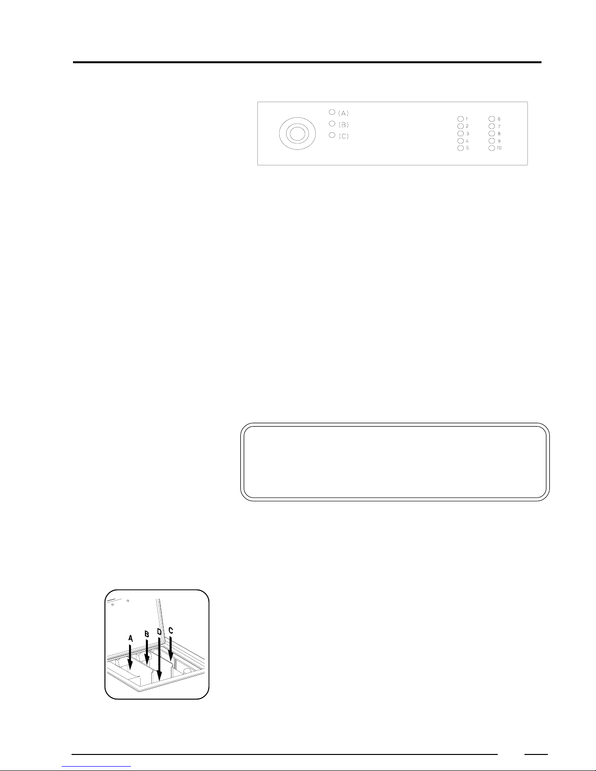
Left compartment A: Pre-wash (1st bath)
Middle compartment B: Main wash (2nd bath)
Right compartment C: Final rinse (conditioner)
Compartment D: Directly in tub
11
Page 12
4
Choose temperature
Start the machine
Orange pilot lights
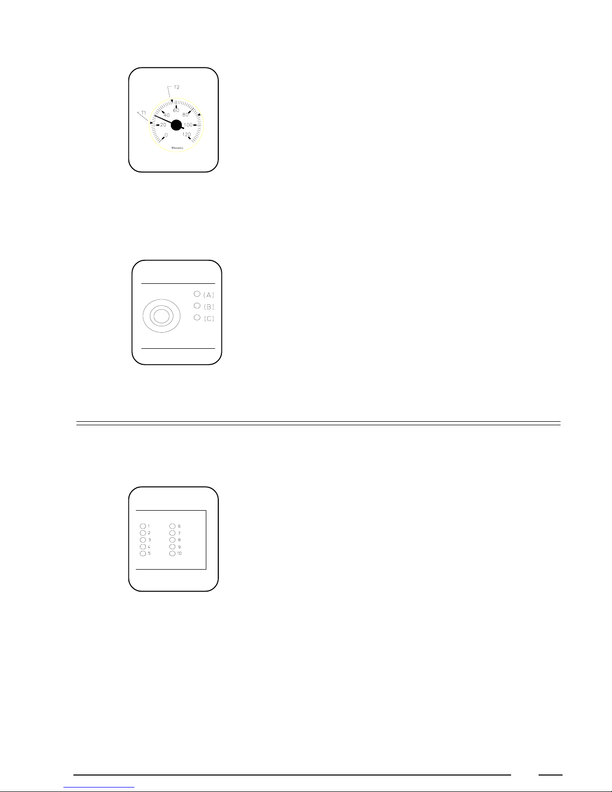
As an option, a thermometer or thermostat with 2 adjustable temperatures can be
installed.
The choice of temperature via the switch buttons can then be replaced by the input
of T1/T2
- T2 = Highest adjustable temperature (Main wash)
- T1 = Lowest adjustable temperature (Pre-wash)
Press the start button (6). When the machine is started, the red control lamp on
the fascia panel (A) will light up.
When the middle orange pilot light (B) lights up, the liquid bleach may be added
manually (Compartment D).
When the bottom orange pilot light (C) lights up, the linen softener is automatically
added or the starch may be added manually (Compartment D).
End of the cycle
Remarks
Function buttons (6-10)
When the red pilot light on the fascia panel turns off, the wash cycle has come to
an end and you can open the door.
Button 6: START.
p
Press this button and release immediately to start a program.
Button 7: STARCH.
To starch at the end of a wash cycle proceed as follows:
p
- In case you dont want to starch some of the linen, remove these first.
- Dissolve the starch in some water.
- Press button 7.
- Press button 6 and release it.
- Add the dissolved starch (in compartment D) when water flows into the soap
dispenser.
- Program sequence: Water inlet - Starch:2' - Drain:30" - Spin:130 - Tumble:30".
- After ending the starch program, press out button 7.
Button 8: HIGH WATER LEVEL (reduced wash action)
p
If you want to wash in a certain program with high water level and reduced
wash action, press button 8. After ending the program, press out button 8.
p
Button 9: NO SPIN
If you want to run a program without spinning, press the button 9 before you
press the start button. After ending that program press out this button 9. You
can also choose 8 & 9 at the same time to wash with reduced wash action, high
water level and without spinning.
Button 10: RAPID ADVANCE.
p
With this button you can at any time skip a part or the rest of the program.
12
Page 13
4
Button Soak
(Option!)
Opening the door in case
of an emergency
Choose a program (1...5) (Dont press button 7)
- Press the pause switch so the light turns on.
- Add detergent and start the machine.
The bath is filled to high water level. A reduced wash action of 3 sec. wash and
12 sec. pause is engaged while the bath is heated to 30° or 40°C, depending on
the selected program 1-4: 40°C, program 5: 30°C.
When the required temperature is reached, the wash action stops until the bath
is cooled down and heating starts again. When the desired pause time is passed,
press out the pause switch. The machine will automatically proceed with its
normal program.
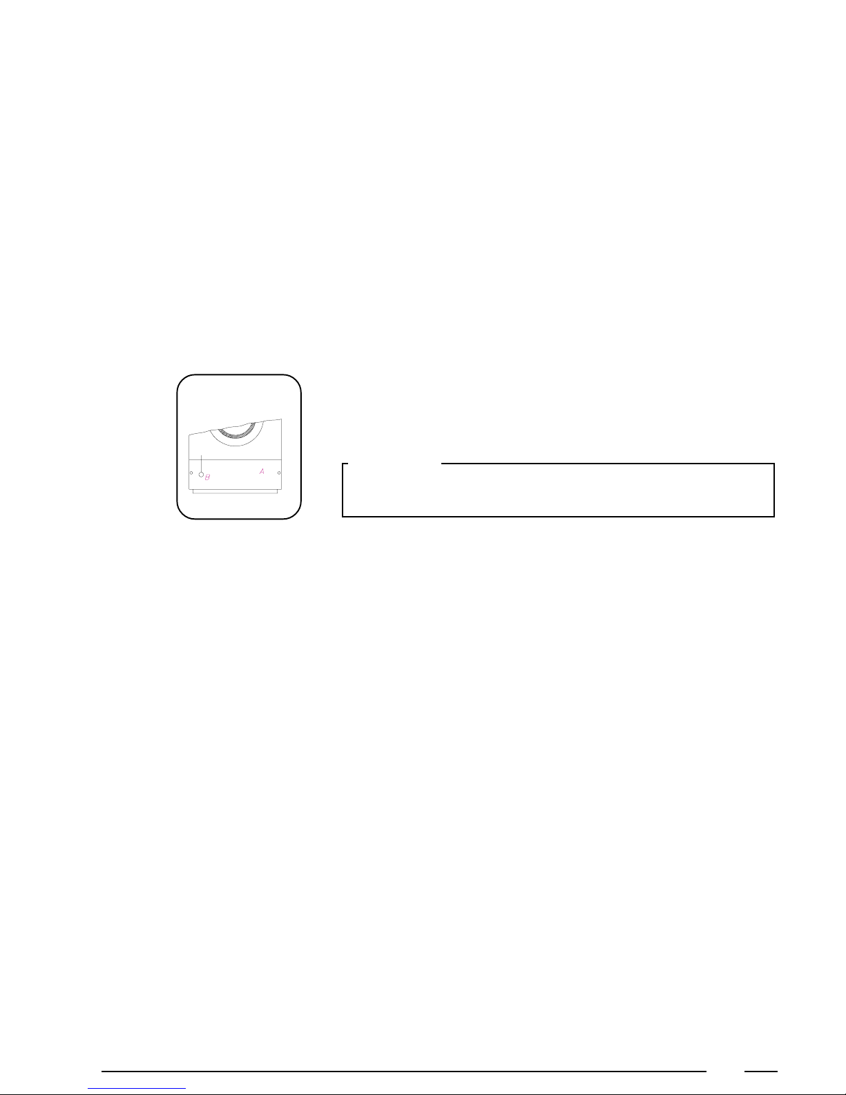
When you want to open the door in case of an emergency (power breakdown,
deficiencies, etc...) remove the service panel (A) at the bottom and pull the left
suspended ring (B) while you press the red button on the doorhandle and open
the door.
Important:
Before opening the door, be sure there is no water left in the tub, and that
the drum has come to a complete stop.
13
Page 14
Machine with CAM-timer and coin meter
4
Open the door
Fill the drum
Close the door
Select program
Press the red button on the doorhandle and open the door.
The machines have 5 wash programs. Sort the linen according to the quality and
the allowed wash temperature. Remove all nails, coins, etc. that can damage the
linen or the machine during the wash cycle. Turn sleeves of overcoats, shirts and
blouses inside out. To increase the wash action and thus the quality of the wash,
it is recommended to mix large and small pieces.
If the machine is filled less than 80% of the capacity, this could prevent a good
operation and can even damage the machine.
Overloading the machine can be the cause of low wash quality.
Press the button of the desired program: (1-5)
1. Hot wash (2 baths)(40°/90°C)
2. Warm wash (2 baths)(40°/60°C)
3. Synthetics (2 baths)(40°/40°C)
4. Synthetics (1 bath)(40°C)
5. Gentle/Wool (1 bath)(30°C or cold)
Remark:
Program 4 & 5 low water level and normal wash action.
Add detergents
It is recommended to use only those detergents with reduced foam. These are
often available in the laundrette, and are also easily found in shops. The dose you
should use is normally indicated on the packing.
Overdosing of soap can lead to poor wash results and foam bubbling out of the
machine can damage it.
Left compartment A: Pre-wash (1st bath)
Middle compartment B: Main wash (2nd bath)
Right compartment C: Final rinse (conditioner)
Compartment D: Directly in tub
14
Page 15
Start the machine
4
Machine with token switch
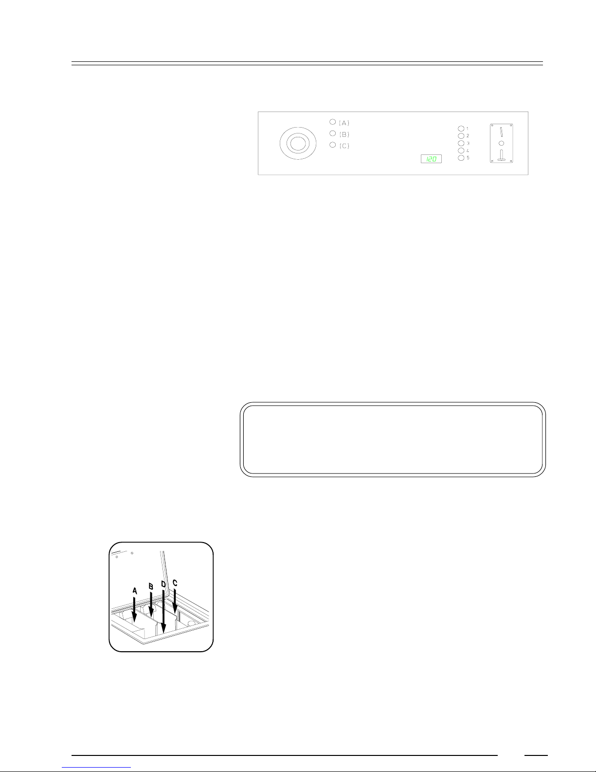
By inserting the token, the machine starts and the pilot light (A) on the fascia
panel will light up.
Machine with coin meter
The amount necessary to start the program is indicated on the display. This total
amount is reduced by the value of each inserted coin. The amount still due
appears each time after a coin has been inserted. When this value becomes 0
the cycle will start, the display will turn off and the red pilot light (A) on the fascia
panel will light up.
Orange pilot lights
End of a cycle
Opening the door in case
of an emergency
When the middle orange pilot light (B) lights up, the liquid bleach may be added
manually (Compartment D).
When the bottom orange pilot light (C) lights up, the linen softener is automatically
added or the starch may be added manually (Compartment D).
When the red pilot light on the fascia panel turns off, the wash cycle has come to
an end and you can open the door.
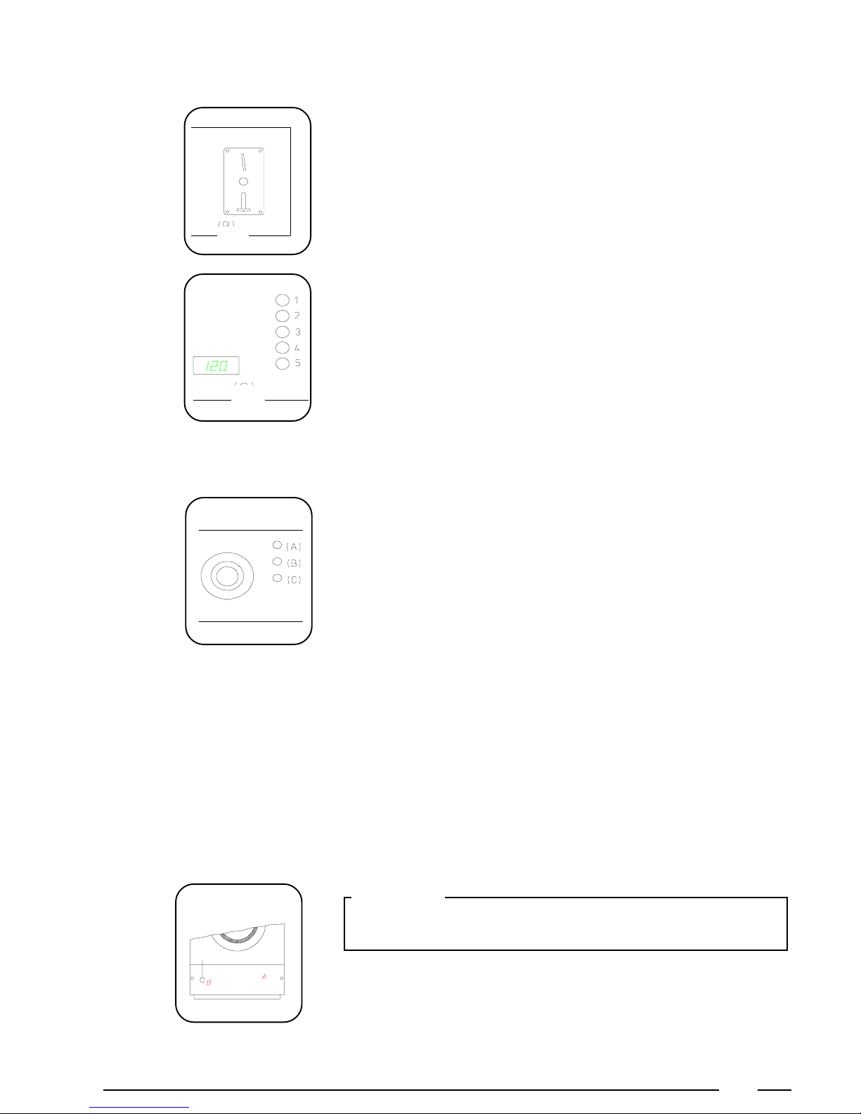
When you want to open the door in case of an emergency (power breakdown,
deficiencies, etc...) remove the service panel (A) at the bottom and pull the left
suspended ring (B) while you press the red button on the doorhandle and open
the door.
Important:
Before opening the door, be sure there is no water left in the tub, and that the
drum has come to a complete stop.
15
Page 16
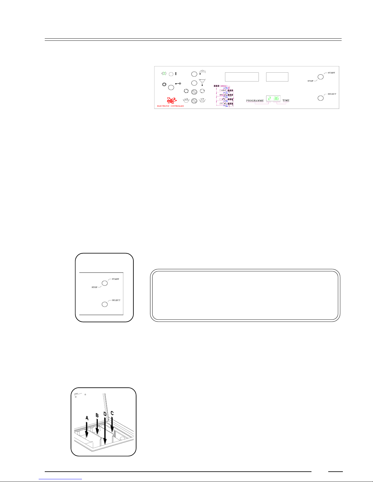
Machine with electronical microprocessor and start button
4
Open the door
Fill the drum
Close the door
Select program
Press the red button on the doorhandle and open the door.
Sort the linen according to the quality and the allowed wash temperature. Remove
all nails, coins, etc. that can damage the linen or the machine during the wash cycle.
Turn sleeves of overcoats, shirts and blouses inside out. To increase the wash
action and thus the quality of the wash, it is recommended to mix large and small
pieces.
If the machine is filled less than 80% of the capacity, this could prevent a good
operation and can even damage the machine.
Overloading the machine can be the cause of low wash quality.
The machine has at least 6 programs (IPSO Belgium). Press the program selection
button (SELECT) as many times until the desired program number appears:
1. Hot wash (2 baths)(40°/90°C)
2. Warm wash (2 baths)(40°/60°C)
3. Synthetics (2 baths)(40°/40°C)
4. Synthetics (1 bath)(40°C)
5. Gentle/Wool (1 bath)(30°C or cold)
6. Starch (1 bath)(cold)
Add detergents
Remark:
These programs can be modified. Other programs can be added. (Max. 9). If this
is desired, contact your distributor.
It is recommended to use only those detergents with reduced foam. These are
often available in the laundrette, and are also easily found in shops. The dose you
should use is normally indicated on the packing.
Overdosing of soap can lead to poor wash results and foam bubbling out of the
machine can damage it.
Left compartment A: Pre-wash (1st bath)
Middle compartment B: Main wash (2nd bath)
Right compartment C: Final rinse (conditioner)
Compartment D: Directly in tub
16
Page 17
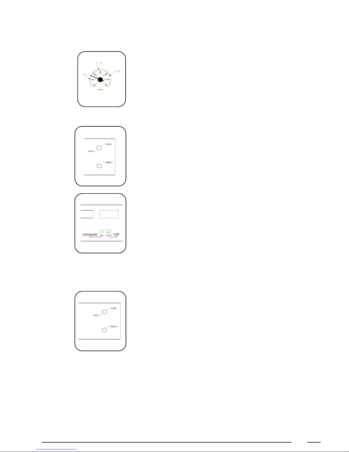
4
Choose temperature
Start the machine
As an option, a thermometer or thermostat with 2 or 3 adjustable temperatures can
be installed.
- T3 = Highest adjustable temperature
- T2 = Middle adjustable temperature
- T1 = Lowest adjustable temperature
Press the start button. When the machine is started, the green pilot light on the
fascia panel will turn off.
During the program, the selected program number remains visible on the left
display. The other two show the remaining program segments of 1 minute. You
can stop the cycle prematurely by pressing the START/STOP button.
End of a cycle
Remarks
When the green pilot light on the fascia panel lights up and the two displays on
the right turn off, the wash cycle has ended and you can open the door.
Rapid Advance
Keep the program select button (SELECT) pressed and then press the START/
STOP button at the same time. By doing this action twice, the middle and right
decimal point will flash at the same time. By pressing the program select button
now you can advance to the following step of the program. By keeping the
program select button pressed it is possible to advance rapidly through a part or
the rest of the program.
To continue normally with the program, press the START/STOP button.
Programmable start
It is possible to start a machine with PLC-9 automatically after a maximum of 99
hours.
Select a program.
p
By keeping the program select button (SELECT) pressed and then pressing
p
the START/STOP button at the same time, -01 appears. Every time you
press the program select button (SELECT) one hour is added to the delay.
The program will only start after the programmed delay has passed.
To undo the programmed start, press START/STOP button.
p
17
Page 18
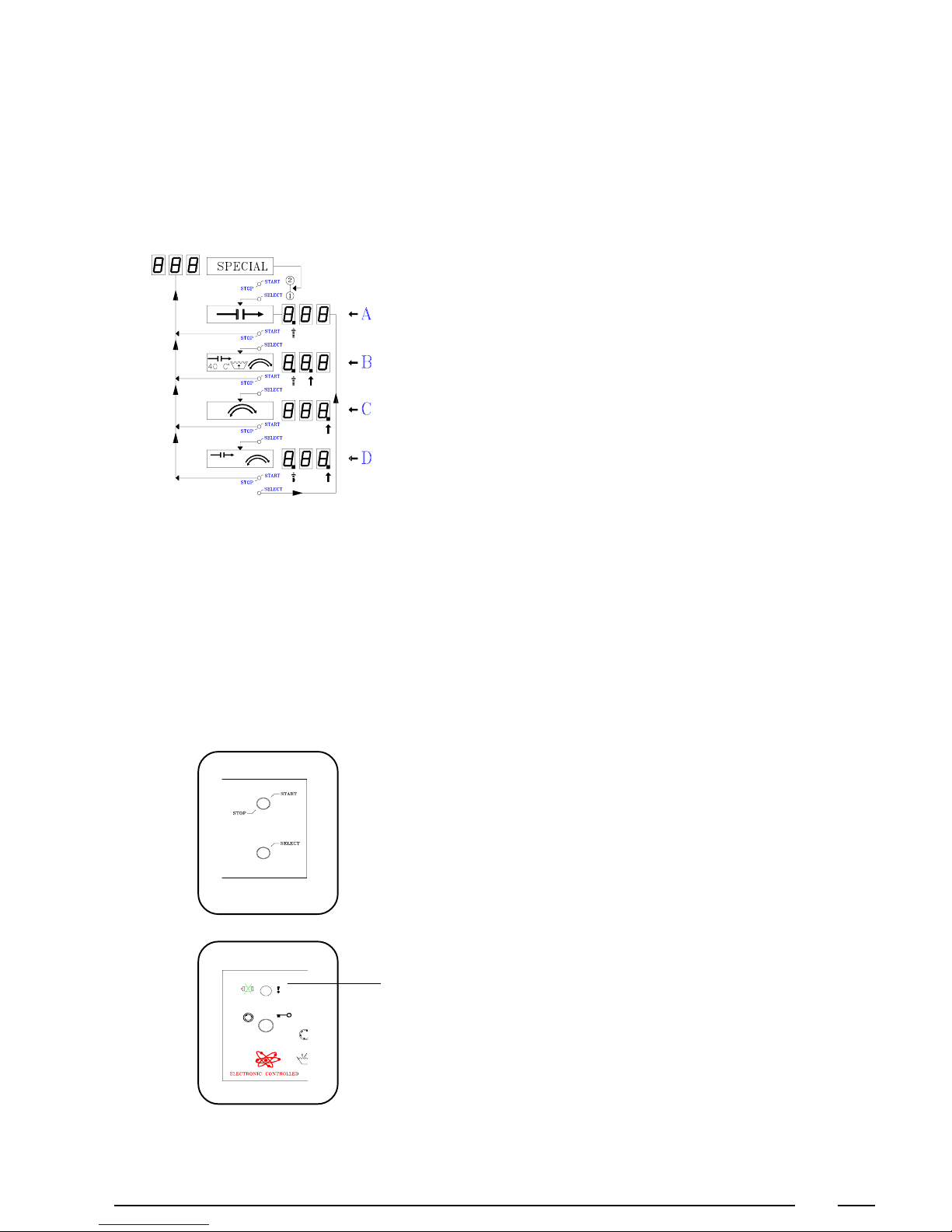
Special functions
By keeping the program select button (SELECT) pressed and then pressing the
START/STOP button at the same time, it is possible to use special functions.
After a while, the left decimal point starts to flash. (A)
p
This means that the program will keep repeating the segment that is now
active (Time stop).
To continue the program normally, press the START/STOP button. Or
if you want to select the following function, press the program select
button (SELECT) once again.
The middle decimal point lights up and the left keeps flashing (B). Now
p
the time will be stopped and the water will be heated to 40°C with reduced
wash action and high water level. By means of this soak program you can
prolongue the pre-wash in case of very dirty linen.
To continue the program normally, press the START/STOP button. Or
if you want to select the following special function, press the program
select button (SELECT) once again.
The right decimal point now lights up (C).
p
This means that all wash actions are being executed at reduced wash
action.
To continue the program normally, press the START/STOP button. Or
if you want to select the following special function, press the program
select button (SELECT) once again.
The right decimal point lights up and the left flashes.
p
Now the program activates a time stop during the wash cycle but in
this case with a reduced wash action.
To continue the program normally, press the START/STOP button.
Test program
By keeping the program select button (SELECT) pressed, when selecting the
program, for more than 5 seconds, you enter the test program (0). This was
specially designed to help the technical service in case of malfunction.
Thermo-magnetic motor protection
When the thermo-magnetic motor protection is activated, the red control pilot
light on the fascia panel will light up and the display will turn off. When the
protection (manually or automatically) is being reset, a flashing S will appear
on the display. This means that you should select again the program.
18
Page 19
Special messages
When starting the program and the door is not closed properly, cdo will
p
appear (Close door).
When starting the program and something is wrong with the water level
p
switches, HLE (high level), LLE (low level) or alternating SLE - tilt
(safety level) will appear.
When one of the required temperatures was not reached during the program,
p
1tE, 2tE, 3tE or 4tE will appear at the end.
When one of the required water levels was not reached during the program,
p
HLE (high level), LLE (low level) or alternating SLE - tilt (safety level)
will appear at the end.
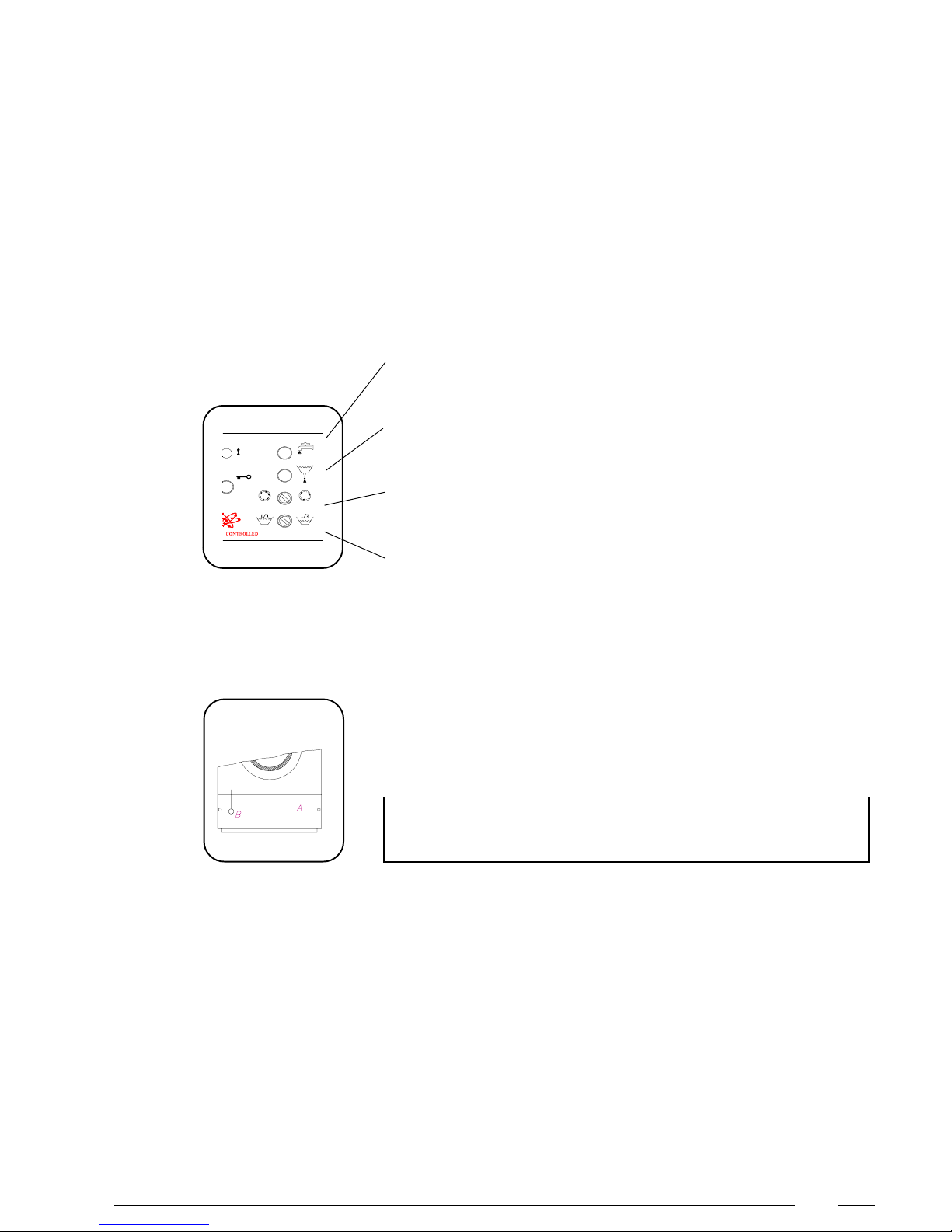
Extra switches and buttons. (Option)
Button adding water
p
With this button the water level in the tub will rise for as long as you press the
button.
Button drain water
p
With this button the water level in the tub will fall for as long as you press the
button.
Switch no high spin
p
By turning this switch to the right, high spin is executed as low spin.
Opening the door in
case of an emergency
Switch lowered water level
p
By turning this switch to the right, you can lower the water level in case of a
smaller wash-load. This can save time, water and energy.
When you want to open the door in case of an emergency (power breakdown,
deficiencies, etc...) remove the service panel (A) at the bottom and pull the left
suspended ring (B) while you press the red button on the doorhandle and open
the door.
Important:
Before opening the door, be sure there is no water left in the tub, and that
the drum has come to a complete stop.
19
Page 20

Technical remarks
Program time (Machine with CAM-timer)
Code 10.1126 - 220 V (50Hz with brown CAM-timer)
There are several possibilities according to cabling, microprocessor, type of heating, tempe-
rature control, water level control, etc.... For your information you can find the details of the
programs for a machine with standard programs, boiler fed (without temperature control nor
water level controls).
12 3 45
Hot Warm Synth. 1 Synth. 2 Wool
water inlet cold+warm cold+warm cold+warm cold+warm cold
pre-wash 630" 630" 430" 630" 630"
water drain 30" 30" 30" 30" 30"
spin 1' 1' 1' ----- -----
water inlet warm 33% cold+ 50%cold+ ----- -----
main wash 12' 12' 9' ----- -----
water drain 30" 30" 30" ----- -----
water inlet cold cold cold cold cold
rinse1 2' 2' 2' 2' 2'
water drain 30" 30" 30" 30" 30"
spin 1' 1' ----- ----- -----
water inlet cold cold cold cold cold
rinse 22'2'2'2'
water drain 30" 30" 30" 30" 30"
spin 1' 1' ----- ----- -----
water inlet cold cold cold cold cold
rinse 3 230" 230" 230" 230" 230"
water drain 30" 30" 30" 30" 30"
spin 3' 3' 1'30" 1'30" 1'30"
delay 30" 30" 30" 30" 30"
tumble 30" 30" 30" 30" 30"
total 3430" 3430" 26 15'30" 15'30"
5
66% warm 50%warm
Remark
In the programs 1 & 2 the pre-wash is installable on 430" or 630" and the main wash installable
on 7' or 12',according to the cabling.
20
Page 21
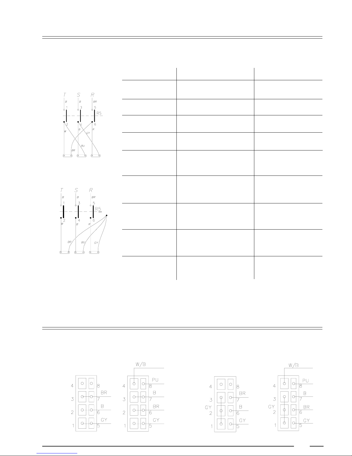
Internal connection of the electrical heating
s
H
Heating 3x220V R5 3x380V R5
4,2kw 3x1,4kw s LC1D0901 H LC1D0901
6kw 3x2kw s LC1D0901 H LC1D0901
9kw 3x3kw s LC1D1810 H LC1D0901
12kw 3x4kw s LC1D0901
12kw 3x2kw s LC1D253 H LC1D090
3x2kw
15kw 3x2kw s LC1D253 H LC1D1810
3x3kw
18kw 3x3kw s LC1D323 H LC1D1810
3x3kw
21kw 3x3kw H LC1D1810
3x4kw s LC1D1810
24kw 3x4kw s LC1D1810
3x4kw s LC1D1810
B = Black
GY = Grey
R = Red
PU = Purple
Br = Brow
BU = Blue
W = White
W/B = White/Black
Remark:
Other executions are available as option
Internal connections of the motors
220V 380V
Low speed High Speed Low speed High speed
21
Page 22
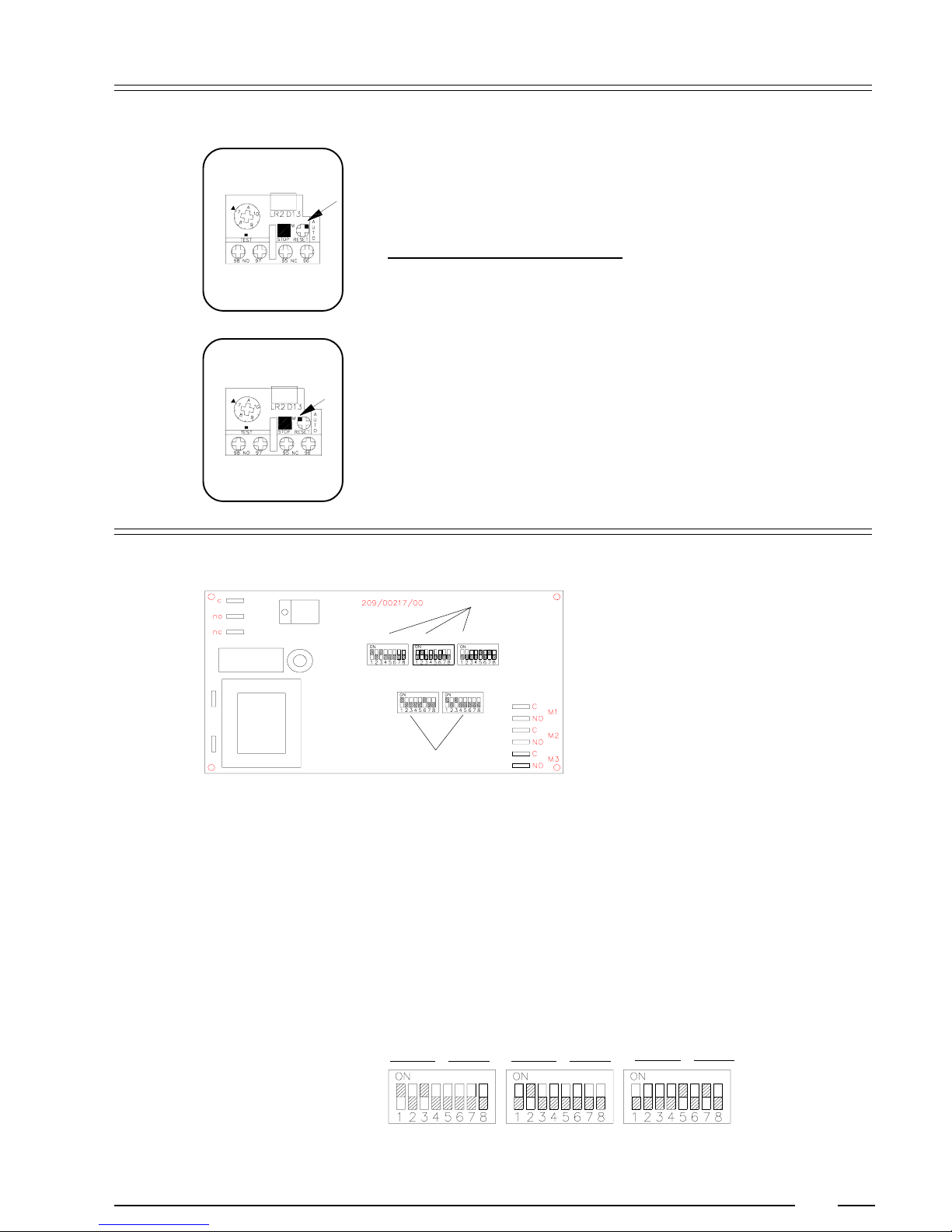
Thermo-magnetic motor protection
5
Autom. reset
Man. reset
The thermic overload relay turns off in case of overloading. Because this relay
is installed on automatical reset, after a while the motors are switched back on
automatically.
Installation and type of overload relay
220V
Machine Type value installation
WE55/73/95 LR2D13109 4-6A 5A
WE110/132 LR2D13149 7-10A 7A
WE165 LR2D13149 7-10A 8A
380V
Machine Type value installation
WE55/73/95 LR2D13089 2,5A-4A 3A
WE110/132/165 LR2D13109 4-6A 4A
Installation of the electronic stepper
Installation of the value of
the coin meters
binaray value 1 2 4 8 1 2 4 8 1 2 4 8 1 2 4 8 1 2 4 8 1 2 4 8
Example 1+0+4+0 0+0+0+0 0+2+0+0 0+0+0+0 0+0+0+0 1+0+4+0
The switches Dip1 up to and including Dip3 are used to install coin meters M1
up to and including M3.
Every coin meter is installed by making an installation with 2 groups of 4 slideswitches.
Every slide-switch has its own binary value (1-2-4-8).
The sum of these binary values gives the input value of one group.
With the first group the tens are installed.
With the second group the units are installed.
Tens
M3 = 50 M2 = 20 M1 = 5
Units
Tens
Units
Tens
Units
22
Page 23

5
Installation of the cycle
price
With the switches Dip4 up to and including Dip5 you can install the cycle price.
With the first three groups of 4 slide-switches you install respectively the
hundreds, tens and units of the cycle price.
In the last group it is possible to place a decimal point with the first two slideswitches.
- With switch 5 all values can be considered divided by 100.
- With switch 6 all values can be considered divided by 10.
Hundreds
Value 1 2 4 8 1 2 4 8 1 2 4 8 1 2 4 8
Example 1+0+0+0 0+2+0+0 1+0+4+0 0+0+0+0
Price : 125
Tens
Units
Decimaal point
23
Page 24
Maintenance of the machine
6
General maintenance
Periodical maintenance
Repair and after-sales
service
Clean the entire cabinet of the machine regularly and remove all traces of soap,
p
etc....
Remove all detergent residue in the soap dispenser with hot water.
p
Clean the door gasket and remove all detergents and other products.
p
Shut off the main water, steam and power connections at the end of each day.
p
Do not change the setting of the water inlet taps on boiler fed machines once
these have been installed.
It is recommended to leave the door and the soap dispenser open after use,
p
to ventilate the machine.
Check regularly if the filters of the water inlet are not blocked by calcification.
p
In case of important malfunctions and deficiencies which you cannot resolve
p
yourself, do not hesitate to contact the technical service of your distributor.
Data distributor:
Data machine:
The manufacturer reserves the right to change the content of this
instruction manual, at all times and without previous notice.
Name: ...................................................................................
Address: ...............................................................................
Tel.: ......................................................................................
Type: .....................................................................................
Program: ...............................................................................
Date of installation: ...............................................................
Installed by: ..........................................................................
Serial number: .......................................................................
Operation voltage and frequency: ..........................................
24
 Loading...