

23456789012345678901
2
2
2
2
2
2
2
2
2
2
2
2
2
2
2
2
2
2
2
2
2
2
2
2
2
2
2
2
2
2
2
2
2
2
2
2
2
2
2
2
2
2
2
2
2
2
2
2
2
2
2
2
2
2
2
2
2
2
2
2
2
2
2
2
2
2
2
2
2
2
2
2
2
2
2
2
2
2
2
2
2
2
2
2
2
2
2
2
2
2
2
2
2
2
2
2
2
2
2
2
2
2
2
2
2
2
2
2
2
2
2
2
2
2
2
2
2
2
2
2
2
2
2
2
2
2
2
2
2
2
2
2
2
2
2
2
2
23456789012345678901
23456789012345678901
23456789012345678901
23456789012345678901
23456789012345678901
23456789012345678901
23456789012345678901
23456789012345678901
23456789012345678901
23456789012345678901
23456789012345678901
23456789012345678901
23456789012345678901
23456789012345678901
23456789012345678901
23456789012345678901
23456789012345678901
23456789012345678901
23456789012345678901
23456789012345678901
23456789012345678901
23456789012345678901
23456789012345678901
23456789012345678901
23456789012345678901
23456789012345678901
23456789012345678901
23456789012345678901
23456789012345678901
23456789012345678901
23456789012345678901
23456789012345678901
23456789012345678901
23456789012345678901
23456789012345678901
23456789012345678901
23456789012345678901
23456789012345678901
23456789012345678901
23456789012345678901
23456789012345678901
23456789012345678901
23456789012345678901
23456789012345678901
23456789012345678901
23456789012345678901
23456789012345678901
23456789012345678901
23456789012345678901
23456789012345678901
23456789012345678901
23456789012345678901
23456789012345678901
23456789012345678901
23456789012345678901
23456789012345678901
23456789012345678901
23456789012345678901
23456789012345678901
23456789012345678901
23456789012345678901
23456789012345678901
23456789012345678901
23456789012345678901
23456789012345678901
23456789012345678901
23456789012345678901
23456789012345678901
23456789012345678901
23456789012345678901
23456789012345678901
23456789012345678901
23456789012345678901
23456789012345678901
23456789012345678901
23456789012345678901
23456789012345678901
23456789012345678901
23456789012345678901
23456789012345678901
23456789012345678901
23456789012345678901
23456789012345678901
23456789012345678901
23456789012345678901
23456789012345678901
23456789012345678901
23456789012345678901
23456789012345678901
23456789012345678901
23456789012345678901
23456789012345678901
23456789012345678901
23456789012345678901
23456789012345678901
23456789012345678901
23456789012345678901
23456789012345678901
23456789012345678901
23456789012345678901
23456789012345678901
23456789012345678901
23456789012345678901
23456789012345678901
23456789012345678901
23456789012345678901
23456789012345678901
23456789012345678901
23456789012345678901
23456789012345678901
23456789012345678901
23456789012345678901
23456789012345678901
23456789012345678901
23456789012345678901
23456789012345678901
23456789012345678901
23456789012345678901
23456789012345678901
23456789012345678901
23456789012345678901
23456789012345678901
23456789012345678901
23456789012345678901
23456789012345678901
23456789012345678901
23456789012345678901
23456789012345678901
23456789012345678901
23456789012345678901
23456789012345678901
23456789012345678901
23456789012345678901
23456789012345678901
23456789012345678901
23456789012345678901
IPSO - LSG n.v.
Instruction manual
WE 55, WE 73, WE 95
WE 110, WE 132, WE 165
Technical specifications
Installation instructions
Operating instructions
Maintenance
Nieuwstraat 146 - B-8560 Wevelgem (Belgium)
Tel. 056/41 20 54 - Fax 056/41 86 74

Contents
1 General safety instructions .............................................................. 3
2 Technical data and dimensions ....................................................... 4
Technical data ................................................................................ 4
Dimensions ..................................................................................... 6
3 Installation and connection ............................................................. 8
Ground ............................................................................................ 8
Anchoring ....................................................................................... 8
Water connection ............................................................................ 8
Water drain ..................................................................................... 9
Main power connection .................................................................... 9
Steam connection ........................................................................... 10
4 Operating instructions ..................................................................... 11
Machine with CAM-timer and 10 buttons ......................................... 11
Machine with CAM-timer and coin meter .......................................... 14
Machine with electronical PLC-9 microprocessor and start button ... 16
5 Technical remarks ............................................................................ 20
Program time (Machine with CAM-timer) .......................................... 20
Internal connection of the electrical heating .................................... 21
Internal connections of the motor .................................................... 21
Thermo-magnetic motor protection .................................................. 22
Installation of the electronic stepper................................................ 22
6 Maintenance of the machine ........................................................... 24
Code: 249/00003/03
16/09/97
Contents
General safety instructions
Ignoring any of the safety instructions can cause serious personal injury and can also cause damage to the linen or the
machine
Read the installation and instruction manual carefully before connecting the
p
machine.
It is recommended that the machine be installed by qualified technicians.
p
The machine should be installed according to the installation instructions. (See
p
chapter 4)
The machine should be grounded according to the instructions in order to
p
eliminate the risk of electrocution.
Do not expose the machine to high humidity or extreme high or low tempera-
p
tures.
Cut off all main water inlets, steam and electrical supplies at the end of each
p
operating day.
1
Before starting repairs or maintenance, shut off all power and water supplies.
p
To prevent fire and explosion:
p
Keep the area around the machine free from inflammable or combustible
products.
Do not put fabrics that are treated with inflammable products into the machine.
These fabrics should be hand-washed or air-dried first.
Always carefully read and follow the instructions on the packing of detergents.
p
Store these products out of the reach of children.
Always take into account the instructions on the labels of clothes.
p
Never allow children to play in the surroundings of a machine.
p
Remark:
These instructions surely cannot prevent all risks of accidents. It is up to the user to act with the utmost
p
precaution.
Do not hesitate to contact the dealer in case of a problem.
p
3

Technical data and dimensions
Technical data
Capacity (dry weight)
1/11 5 kg 6,6 kg 8,6 kg
1/10 5,5 kg 7,3 kg 9,5 kg
1/9 6,1 kg 8,1 kg 10,5 kg
Cylinder
Diameter 530 mm 530 mm 530 mm
Depth 295 mm 345 mm 440 mm
Volume 55 Lit. 73 Lit. 95 Lit.
Cabinet
Height 1005 mm 1005 mm 1110 mm
Width 660 mm 660 mm 660 mm
Depth 670 mm 670 mm 770 mm
Front loading
Diameter door opening 300 mm 300 mm 300 mm
Door height 360 mm 360 mm 455 mm
To center 510 mm 510 mm 605 mm
Speed
Wash 50 rpm
Spin 500 rpm
G-force
Spin 74
Motor(3 phase)
Wash 18p. 290rpm 120 W 120 W 120 W
Spin 2p. 2900 rpm 370 W 370 W 550 W
Drain valve
Depend-O-Drain 6/4"
Water supply
Hard, soft, warm water and cool-down 3/4"
Steam connection
Steam connection 3/8"
Heating
Electrical 220/380 V 4,2/6/9 kw
Electrical 380 V 12 kw
Steam X
Warm water (without additional heating) X
Warm water (with additional heating) X
Packing dimensions
(H x W x D) 1140x732x832mm (WE55/73/95)
1230x732x950mm (WE95)
Weight
N et 16 5 k g 1 70 kg 17 8 k g
Gross 220 kg 225 kg 230 kg
2
WE 55 WE 73 WE 95
4

Capacity (dry weight)
Cylinder
Cabinet
Front loading
Speed
G-force
Motor(3 phase)
Drain valve
Water supply
Steam connection
Heating
Packing dimensions
Weight
2
WE 110 WE 132 WE 165
1/11 10 kg 12 kg 15 kg
1/10 11 kg 13,2 kg 16,5 kg
1/9 12,2 kg 14,5 kg 18,3 kg
Diameter 650 mm 650 mm 650 mm
Depth 330 mm 400 mm 500 mm
Volume 110 Lit. 132 Lit. 165 Lit.
Height 1170 mm 1170 mm 1170 mm
Width 780 mm 780 mm 780 mm
Depth 760 mm 760 mm 860 mm
Diameter door opening 300 mm 300 mm 300 mm
Door height 465 mm 465 mm 465 mm
To center 615 mm 615 mm 615 mm
Wash 50 rpm
Spin 500 rpm
Spin 88
Wash 18p. 290rpm 220 W 220 W 280 W
Spin 2p. 2900 rpm 1100 W 1100 W 1300 W
Depend-O-Drain 6/4"
Hard, soft, warm water and cool-down 3/4"
Steam connection 3/8"
Electrical 220/380 V 12/15/18 kw
Electrical 380 V 21/24 kw
Steam X
Warm water (without additional heating) X
Warm water (with additional heating) X
(H x W x D) 1310x850x922mm (WE110/132)
1310x850x1022mm (WE165)
Net 230 kg 235 kg 245 kg
Gross 285 kg 290 kg 315 kg
5
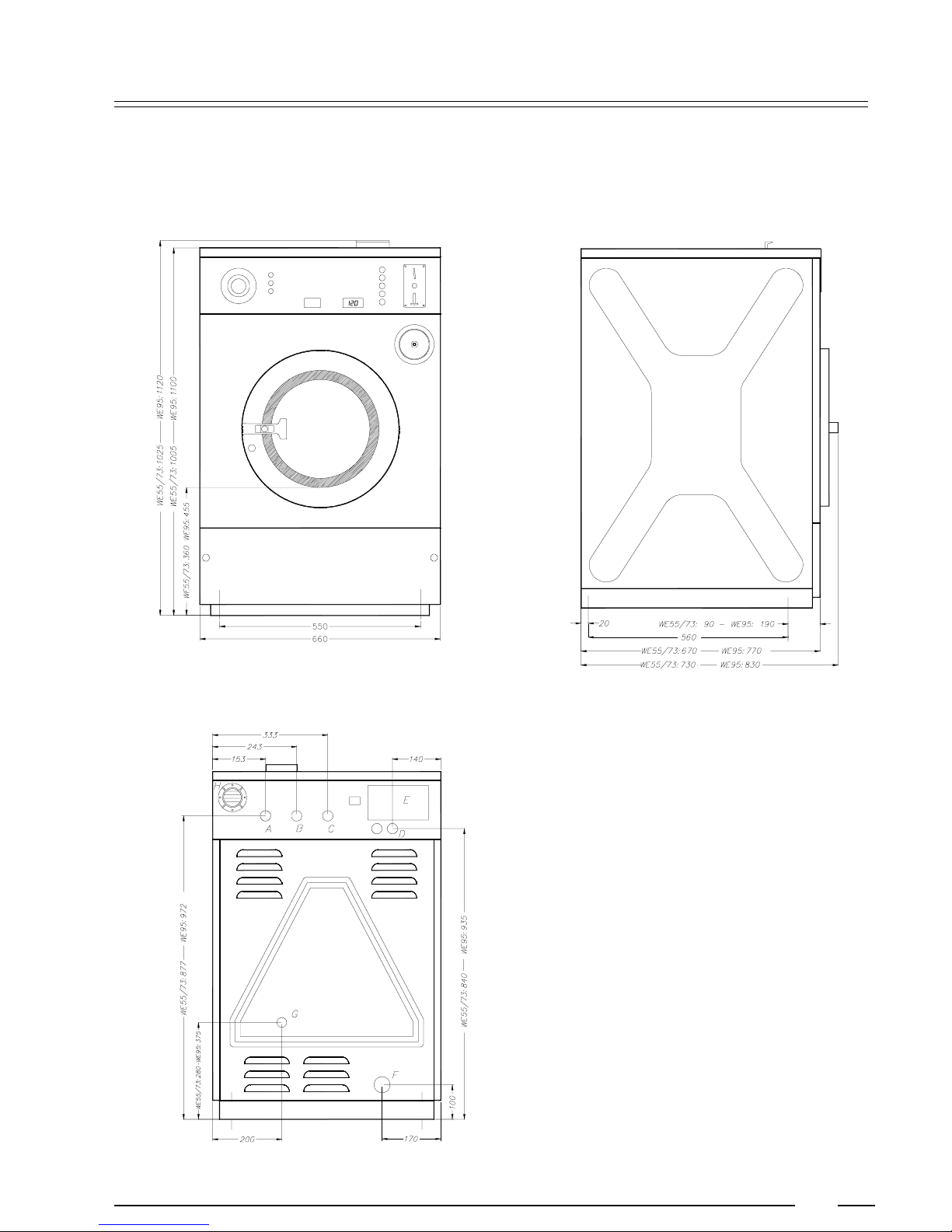
Dimensions
WE55/73/95
2
A. Hard water connection 3/4"
p
B. Warm water connection 3/4"
p
C. Soft water connection 3/4"
p
D. Electrical connection
p
E. Electrical connection clamps
p
F. Water drain
p
G. Steam connection
p
H. Ventilation soap dispenser
p
6
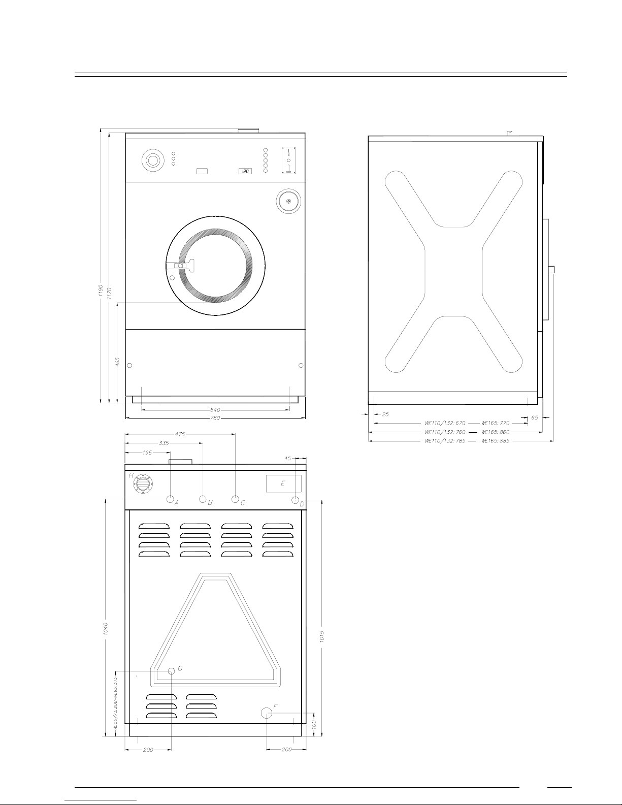
WE110/132/165
2
A. Hard water connection 3/4"
p
B. Warm water connection 3/4"
p
C. Soft water connection 3/4"
p
D. Electrical connection
p
E. Electrical connection clamps
p
F. Water drain
p
G. Steam connection
p
H. Ventilation soap dispenser
p
7
Installation and connection
Surface
The machine must be securely fixed on a flat surface (metal base, concrete or solid
ground). The anchoring is to be done on the provided places (A) in the base. (See
Dimensions 2)
The machine must be placed entirely level. For easy maintenance it is recommended to keep a minimal distance of 600 mm between the wall and the back of the
machine.
If several machines are placed next to each another, there should be a minimal
distance of 30 mm between each machine.
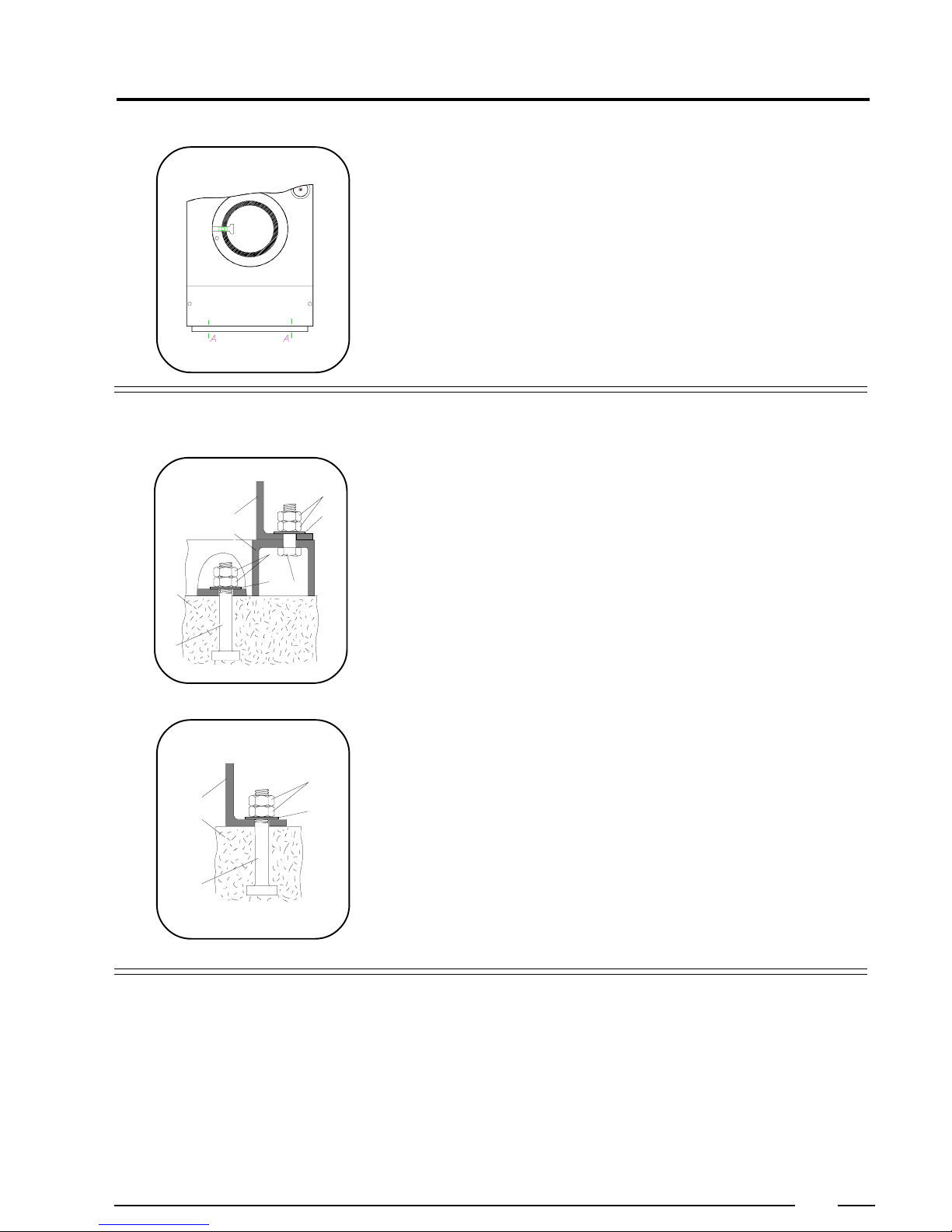
Anchoring
On a metal base
D
E
F
D
B
A
CG
C
The machines must be fixed on a metal base which is securely anchored on a
concrete base.
A: Bolt M12 (WE55/73/95), M16 (WE110/132/165)
B: Concrete base (WE55/73: 20cm, WE95/110: 30cm, WE132/165: 40cm)
C: Washer 40x17x4
D: Nut M12 (WE55/73/95), M16 (WE110/132/165)
E: Base of the machine
F: Metal base
3
E
B
A
Water connection
Directly on the ground
D
C
The machine must be anchored directly on a concrete base.
A: Bolt M12 (WE55/73/95), M16 (WE110/132/165)
B: Concrete base (WE55/73: 20cm, WE95/110: 30cm, WE132/165: 40cm)
C: Washer 40x17x4
D: Nut M12 (WE55/73/95), M16 (WE110/132/165)
E: Base of the machine
The machine is delivered with hoses with 3/4" connections. These hoses fit the
water inlet valves of the machine and the main water inlet taps. To ensure the
optimal functioning of the water inlet valves, the water pressure on the inlet should
be between 0,5 and 10 kg/cm² (7 and 145 psi). If the pressure is too low, the cycle
time will increase considerably.
In case of boiler fed machines, a minimum of hot water of 90°C should be available:
For the WE55: 50 l. WE 110: 90l.
For the WE73: 65 l. W E 132: 120l.
For the WE95: 80 l. W E 165: 140l.
8
 Loading...