

Page 1

®
SkyTracker™ Camera Mount
Instruction Manual
Product #3300B, #3300W and #3301
Page 2
Table of Content
Table of Content ...................................................................................................................... 2
1. SkyTrackerTM Camera Mount Overview .............................................................................. 3
2. SkyTrackerTM Camera Mount Assembly.............................................................................. 3
2.1. Introduction ................................................................................................................... 3
2.2. Parts List....................................................................................................................... 3
2.3. Assembly Terms ........................................................................................................... 5
2.4. SkyTrackerTM Camera Mount Assembly ....................................................................... 6
3. Maintenance and Servicing ............................................................................................... 12
3.1. Maintenance ............................................................................................................... 12
3.2. iOptron Customer Service........................................................................................... 12
3.3. Product End of Life Disposal Instructions.................................................................... 12
3.4. Battery Replacement and Disposal Instructions.......................................................... 12
Appendix A. Technical Specifications.................................................................................... 13
IOPTRON ONE YEAR TELESCOPE, MOUNT, AND CONTROLLER WARRANTY............ 14
NEVER USE A TELESCOPE TO LOOK AT THE SUN WITHOUT A PROPER FILTER!
Looking at or near the Sun will cause instant and irreversible damage to your eye.
Children should always have adult supervision while observing.
Rev.1.1
iOptron reserves the rights to revise this instruction without notice. Actual color/contents/design may differ from those described in this
instruction.
WARNING!
2
Page 3

1. SkyTrackerTM Camera Mount Overview
Thank you for choosing the new iOptron SkyTrackerTM camera mount for astrophotography.
This portable mount makes it easy to take long exposures of the night sky without streaking or star
trailing.
The SkyTrackerTM mount is simple to set up. Just attach the unit to a camera tripod with 3/8”
thread. Then slide and lock your digital camera into the saddle. Align SkyTracker
North Star, through the polar sight hole on the mount, or using a iOptron AccuAligning
TM
to Polaris, the
TM
dark field
illuminated polar scope. Then turn on the motor and it keeps your camera tracking at the same speed
the earth rotates! The unique DC servo motor keeps your camera in motion to avoid star trails and
allows you to take long exposures for beautiful images of the night sky.
Features:
y Attaches to a camera tripod with 3/8” thread
y Accepts cameras weighing up to 6.6 lbs (3 kg)
y Auto-tracking for smooth camera motion perfect for long-term exposures
y Cast aluminum body with plastic spray finish
y Built in compass and latitude adjustment for easy polar alignment
y Includes iOptron AccuAligning
TM
dark-field illuminated polar scope (#3300B and #3300W
only)
y Up to 24 hours of operation on 4 AA batteries
y Padded carry bag included
y Optional ball heads available separately
y Optional AC/DC adapter
2. SkyTrackerTM Camera Mount Assembly
2.1. Introduction
You have just purchased a tracking camera mount that is capable of taking you to a new level
of astrophotography. When aligned the polar axis of the SkyTracker
North Pole (CNP), or celestial South Pole (CSP), the mount will provide rotation matching the celestial
sphere rotation around the Earth. Since all celestial objects appear to rotate around the CNP, or CSP,
the polar axis allows the mount to rotate with the celestial sphere and provide accurate tracking for
visual observations and astrophotography.
The AccuAligning
TM
polar scope, along with the Quick Polar Alignment procedure, will provide
an easy and accurate polar alignment for the mount.
The SkyTracker mount is a totally new camera mount for astrophotography. The following
sections of this manual provide the detailed steps required to successfully set up and operate the
SkyTracker
TM
mount.
TM
camera mount with the celestial
2.2. Parts List
PARTS INCLUDED:
TM
The SkyTracker
• SkyTracker
• Padded carry bag
• AccuAligning
camera mount shipping box contains:
TM
camera mount
TM
dark field illuminated polar scope (for models #3300B and #3300W only)
3
Page 4
TM
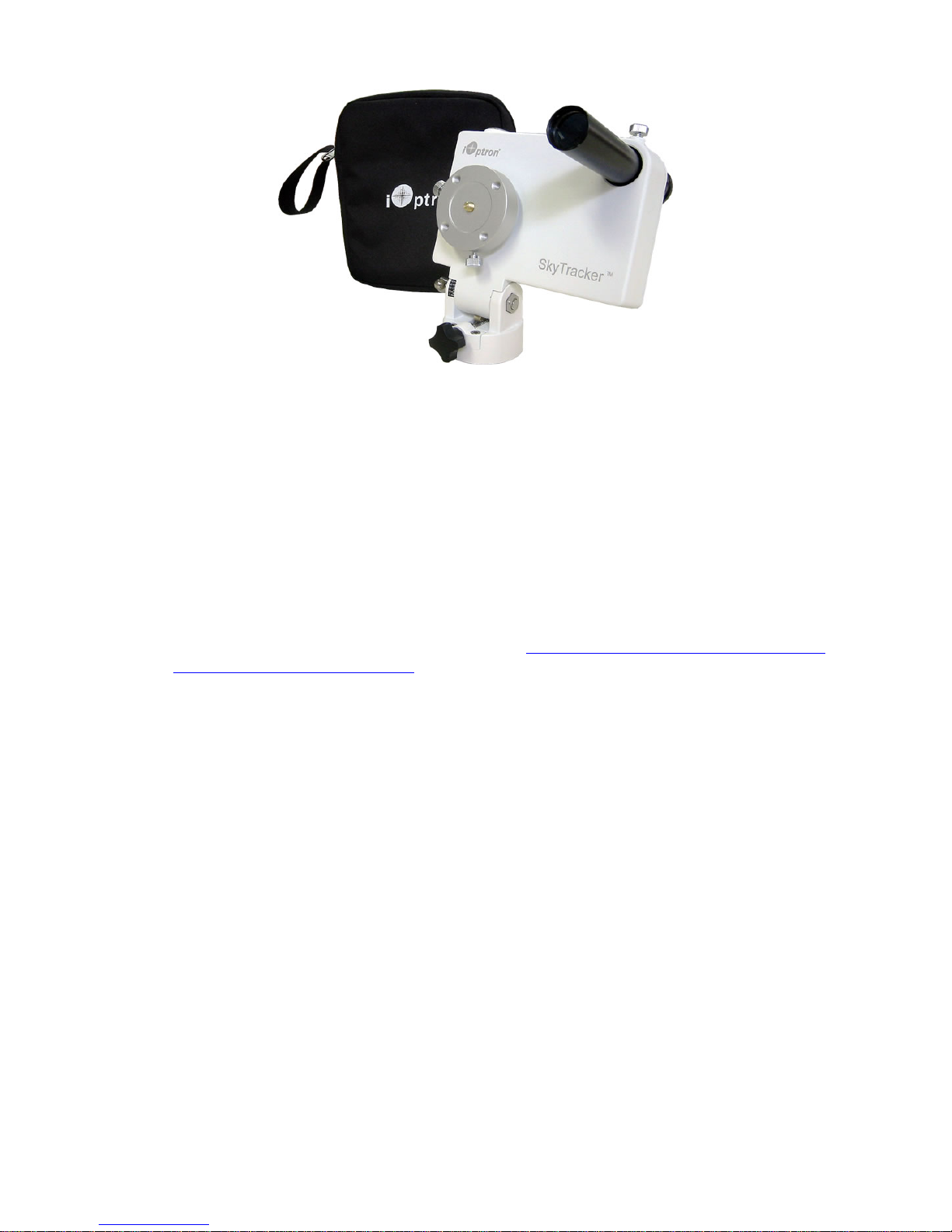
Figure 1. Parts in a SkyTracker
#3300 package
PARTS NEEDED:
The following parts are needed to take astrophotography but are not included in the package:
• A sturdy tripod with 3/8” thread. If your tripod only has a 1/4” thread, you need get a 1/4” to
3/8” tripod adapter screw
• Fresh 4 AA batteries
• Ball head adapter
• DLSR camera
YOU MAY NEED IT FOR POLAR ALIGNMENT:
• iPhone/iPad app for accurate polar alignment (https://itunes.apple.com/us/app/ioptron-
polar-scope/id564078961?mt=8)
ONLINE CONTENTS (click under “Support” menu) www.iOptron.com
• This manual
• Tips for set up
• Reviews and feedback from other customers
4
Page 5
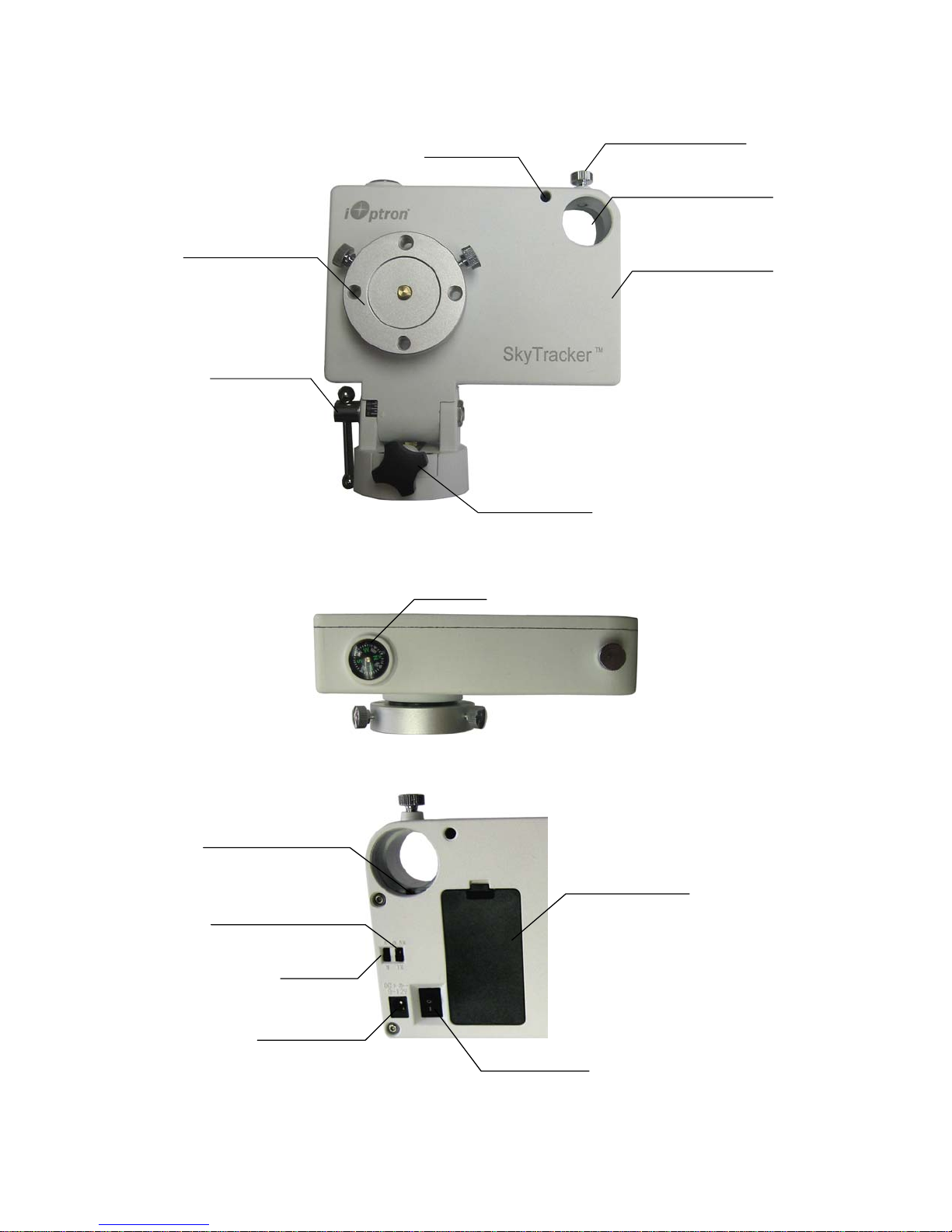
2.3. Assembly Terms
Polar sight hole
Camera mounting block
Lat. adjust. lock
Lat. Adjust. screw
Polar scope lock screw
Polar scope mounting hole
SkyTracker body
Figure 2. Front view of a SkyTracker
Compass
Figure 3. Top view of a SkyTracker
Power indicator/
Polar scope illuminator
Battery compartment cover
Tracking speed switch
N/S switch
DC power in
Power switch
Figure 4. Part of back view of a SkyTracker
5
Page 6
2.4. SkyTrackerTM Camera Mount Assembly
NOTE: The SkyTrackerTM mount is a precision astronomical instrument. It is highly
recommended that you read the entire manual and become familiar with the nomenclature and
functions of all components before starting the assembly.
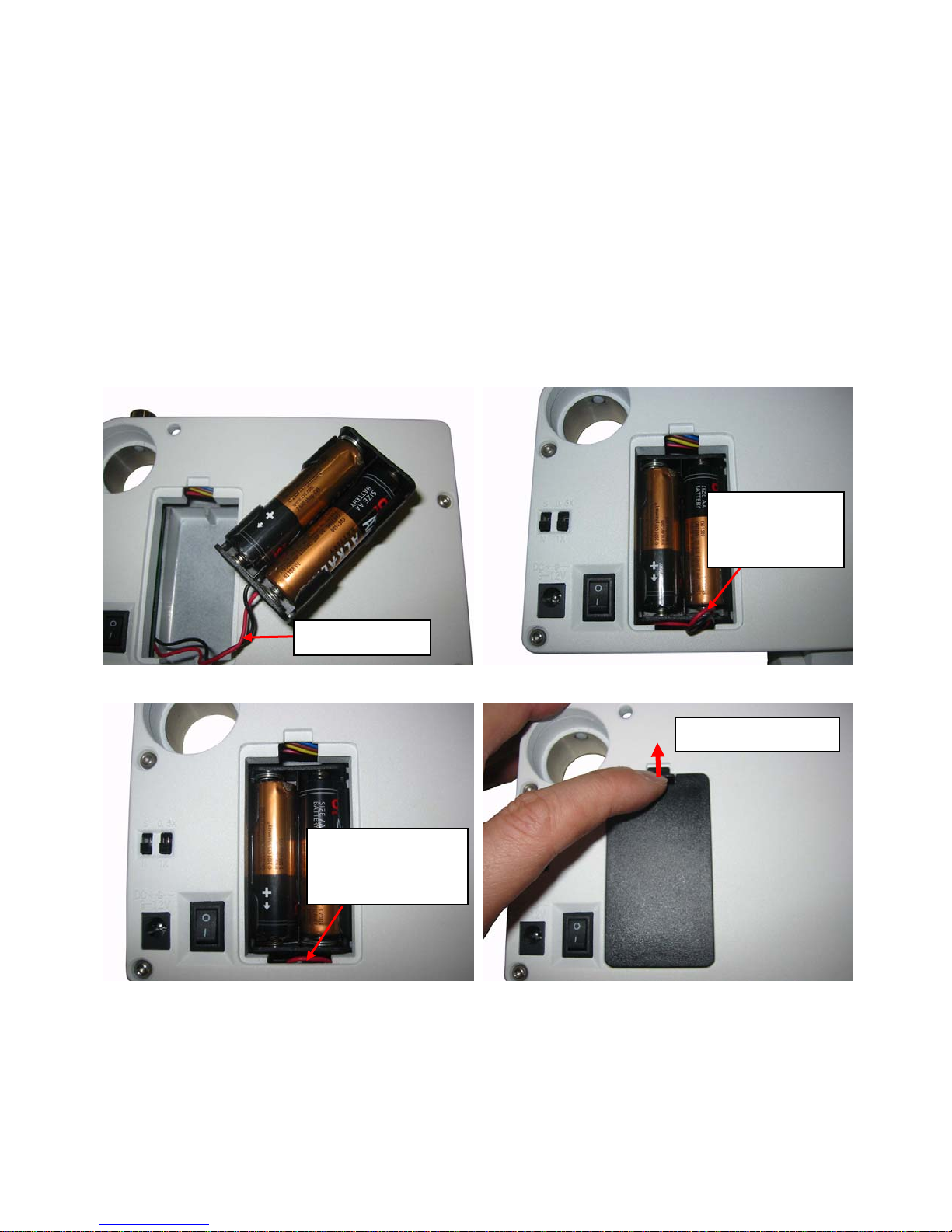
STEP 1. Install batteries
The battery compartment is located at the back of the SkyTracker
compartment cover and gently pull out the battery holder from the compartment. Insert 4 fresh AA
batteries (not included) into the holder (Figure 5a). Since it is a tight fit, you may find that you cannot
put the battery cover back due to the wires. Straighten the battery holder wires, slide the battery
holder back into the battery compartment and leave the wires outside, as shown in Figure 5b. Then
push the battery holder wires down into the battery compartment, as shown in Figure 5c. Place the
battery cover back onto the battery compartment and push the cover hook up to secure the battery
cover (Figure 5d)
TM
mount (Figure 4). Lift the battery
Leave wires
outside battery
compartment
Battery wires
(a) (b)
Lock battery cover
Push wires down
into battery
compartment
(c) (d)
Figure 5. Install batteries
6
Page 7
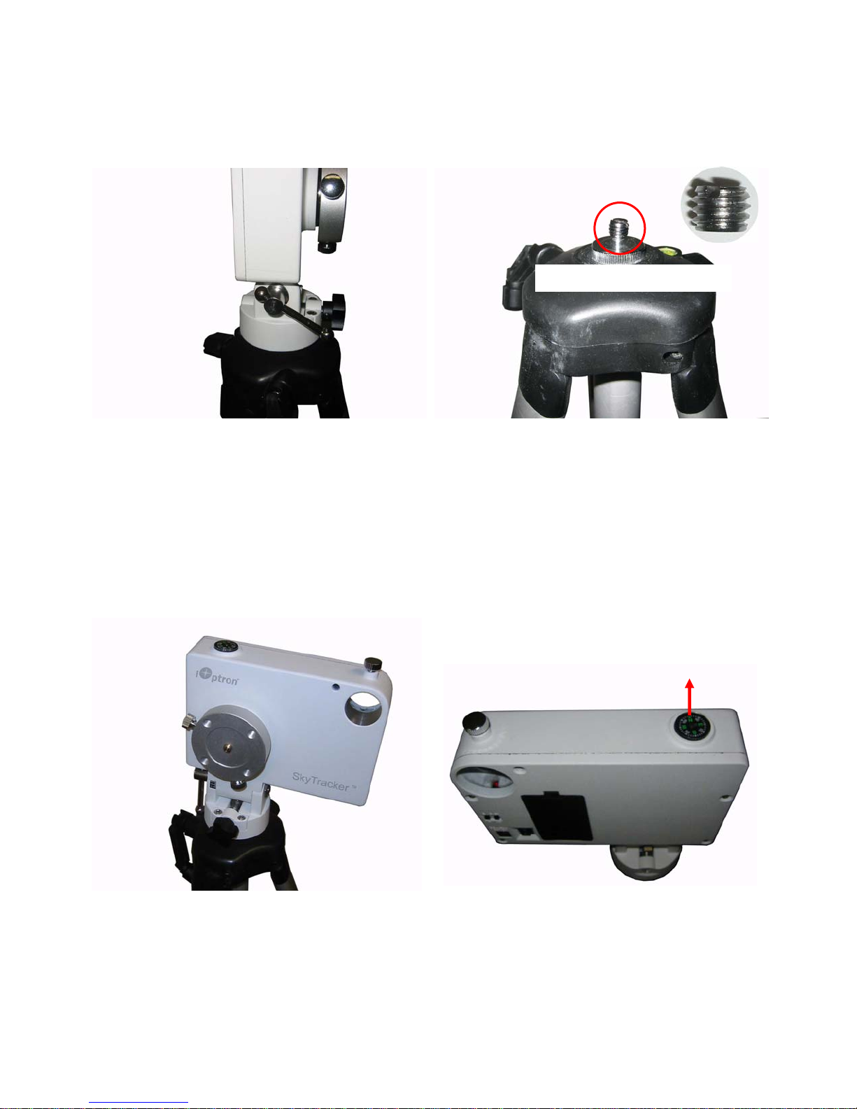
STEP 2. Attach the SkyTrackerTM Mount
r
TM
Carefully thread the SkyTracker
mount onto your tripod and make sure it is securely tightened. The
mount base has a 3/8” threaded socket. If your tripod only has a 1/4” threaded post, a 1/4” to 3/8”
tripod adapter screw (not included) is needed, as shown in Figure 6.
1/4” to 3/8” tripod adapte
Figure 6. Install SkyTracker onto a tripod
TM
STEP 3. Set the SkyTracker
Release Latitude lock a half turn. Set the latitude at zero mark (Figure 7) by turning the Latitude
adjustment screw and retighten the Latitude lock. Rotate the tripod to make the SkyTracker
mount
TM
mount
face north by making the compass N-S perpendicular to the mount front edge (Figure 8). If the
compass does not move freely, adjust the tripod leg to make it as level as possible.
N
Figure 7. Set latitude to zero mark
STEP 4. Set the latitude and find the Polaris
Release Latitude lock a half turn. Set the latitude at your current latitude by turn the Latitude
adjustment screw and retighten the Latitude lock, as indicated in Figure 9. You may find your current
Figure 8. Face the mount north
7
Page 8
latitude from your smart phone or internet using your current address. If the north pointing and the
latitude set are correct, you should be able to find the Polaris through the Polar Sight Hole. Center the
Polaris inside the Polar Sight Hole as good as possible for the polar alignment. Retighten all the
screws and locks.
For those located in the southern hemisphere, use Sigma Octantis in Octans as the pole star.
Figure 9. Set current latitude
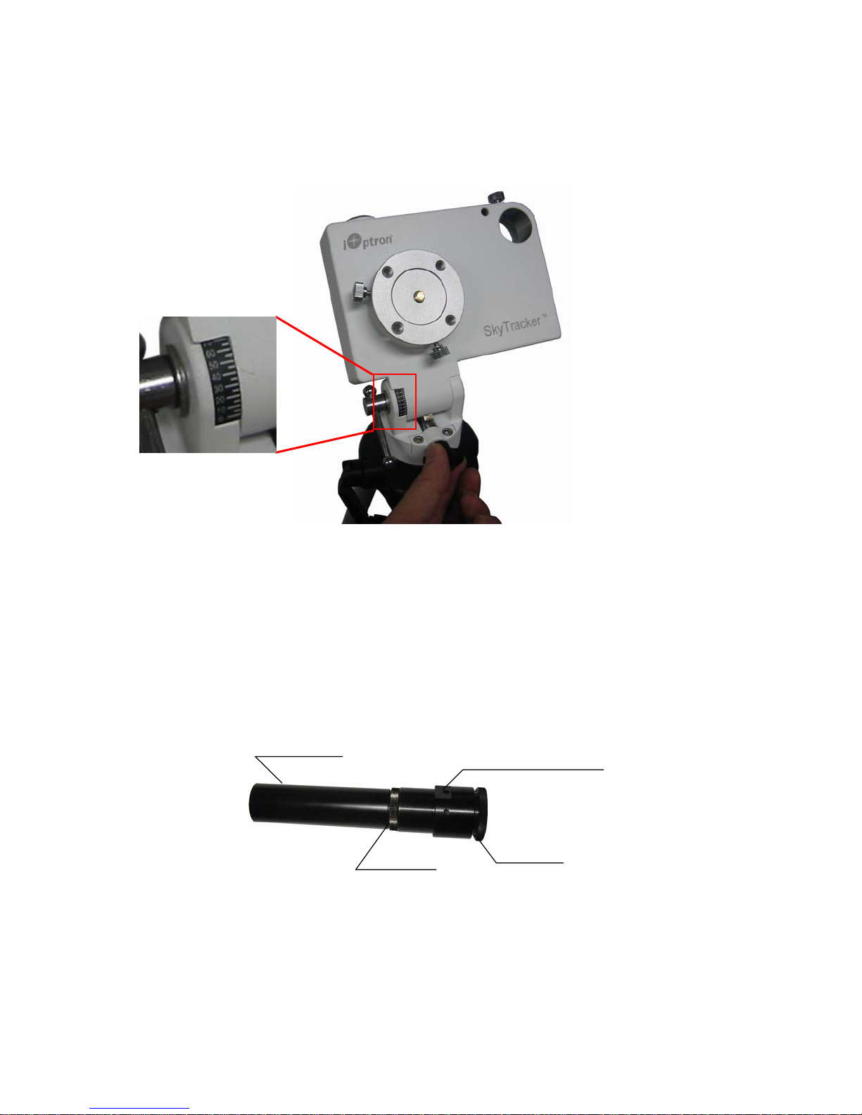
STEP 5. Easy Polar Alignment
This STEP will discuss how to use iOptron’s AccuAligning
10) for easy and accurate polar alignment. You may skip this part and directly go to STEP 6, if your
model does not equipped with a polar scope (Model #3301). In order for the SkyTracker
TM
dark field illuminated polar scope (Figure
TM
mount
tracking properly, it has to be accurately polar aligned. This is achieved by making the polar axis of
the mount parallel to that of the Earth’s axis of rotation.
Objective lens
Lock ring
Reticle illumination inlet
Eyepiece
Figure 10. AccuAligningTM dark field illuminated polar scope
Before installing the polar scope onto the mount, face the polar scope to a bright source, such as the
sky (but not the SUN) or a lamp from distant. Adjust the eyepiece to focus the reticle pattern. Then
face the polar scope to a distant object and look through the eyepiece. If you can not see the distant
object clearly, the polar scope is not focused for your eyesight. Release a few turns of the Lock ring.
Turn the Objective lens until the image is focused. Retighten the Lock ring.
8
Page 9

Turn the Polar Scope Lock Screw until it does not intrude into the Polar Scope Mounting Hole. The flat
surface inside the mounting hole is for polar scope alignment and the LED acts as both the power
indicator and the illuminating light for the polar scope reticle, as shown in Figure 11. Gently insert the
polar scope into the Polar Scope Mounting Hole with the flat platoon on the polar scope face down.
Push the polar scope all the way in so the flat surfaces inside the hole will align to the flat platoon on
the polar scope and the LED will sit right to the little opening on the flat platoon. Finger tighten (not too
tight) the Polar Scope Lock Screw (Figure 12).
Figure 11. Release polar scope lock screw
Press the power switch on the mount to turn the SkyTracker
mount on. Look
through the polar
scope eyepiece.
Adjust the eyepiece to
bring the reticle dial in
focus. As indicated in
Figure 13, the Polar
Scope Dial has been
divided into 12 hours
along the angular
direction with halfhour tics. There are 2
groups, 6 concentric
Figure 13. Polar scope dial
circles marked from
36’ to 44’ and 60’ to
70’, respectively. The 36’ to 44’ concentric circles are used
for polar alignment in the northern hemisphere using Polaris.
While the 60’ to 70’ circles are used for polar alignment in
the southern hemisphere using Sigma Octantis.
Figure 12. Installed polar scope
TM
To maximize the benefits of the iOptron polar scope for
polar alignment, you need to know where the Polaris is in
the northern hemisphere. You may find this information via
an iPhone/iPad app (iOptron Polar Scope in Apple iTune
store). Shown in Figure 14 is a screen shot of an iPhone
Figure 14. Polar scope chart
on an iPhone
9
Page 10

chart. For example, on December 3, 2012, 12:48:36 in Boston, USA (Lat N42º30’28” and Long
W71º08’49”), the Polaris Position is 10hr 24.1m and r = 40.8min (the green dot on the chart).
Adjust the mount in latitude (using Latitude Adjustment Screw) and azimuth (heading, adjusting tripod)
direction to place Polaris in the same position on the Polar Scope Dial as indicated on your
iPhone/iPad screen. In this case, the Polaris will be located at a radius of 40.8’ and an angle of 10
hour 24.1 minute.
If you don’t have this application, you still can get a better polar alignment by placing Polaris at the
center of the polar scope dial.
STEP 6. Install ball head
Take off the camera mounting block from the SkyTracker by releasing two thumb screws that hold the
camera mounting block in place, as indicated in Figure 15. Mount the ball head (available as
accessory) onto the camera mounting block by threading it onto the brass central mounting screw
(Figure 16). Make sure they are tightened enough that there is no relative movement between the
mounting block and ball head. Reinstall the mounting block with ball head back to the SkyTracker.
Tighten the thumb screws to make sure that the mounting block will not slip.
Figure 15. Remove camera mounting block
Figure 16. Install ball head
10
Page 11
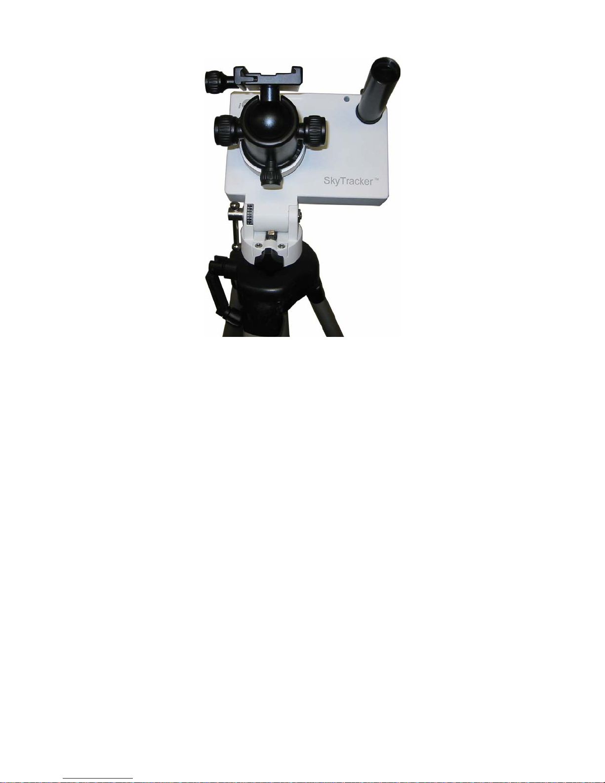
Figure 17. SkyTracker with Polar Scope and a ball head installed
STEP 7. Mount a camera and start SkyTracking
Install a DLSR camera onto the ball head and point the camera to the sky you are interested in. Make
sure all the screws/locks are tightened. Select S/N switch based on your location. Select 1X or 1/2
tracking speed. Double check the polar alignment and realign it if needed. Turn the power switch on
and enjoy the SkyTracking.
11
Page 12

3. Maintenance and Servicing
3.1. Maintenance
The SkyTrackerTM camera mount is designed to be maintenance free. Do not overload the
mount. Do not drop the mount. This will damage the mount or degrade the tracking accuracy
permanently. Use a damp cloth to clean the mount if necessary. Do not use solvent.
If your mount is not to be used for an extended period, remove the battery from the mount.
3.2. iOptron Customer Service
If you have any question concerning your mount, contact iOptron Customer Service
Department. Customer Service hours are 9:00 AM to 5:00 PM, Eastern Time, Monday through Friday.
In the unlikely event that the mount requires factory servicing or repairing, write or call iOptron
Customer Service Department first to receive an RMA# before returning the mount to the factory.
Please provide details as to the nature of the problem as well as your name, address, e-mail address,
purchase info and daytime telephone number. We have found that most problems can be resolved by
e-mails or telephone calls. So please contact iOptron first to avoid returning the mount for repair.
It is recommended to send technical questions to support@ioptron.com
1.781.569.0200.
3.3. Product End of Life Disposal Instructions
This electronic product is subject to disposal and recycling regulations that vary
by country and region. It is your responsibility to recycle your electronic equipment per
your local environmental laws and regulations to ensure that it will be recycled in a
manner that protects human health and the environment. To find out where you can
drop off your waste equipment for recycling, please contact your local waste
recycle/disposal service or the product representative.
3.4. Battery Replacement and Disposal Instructions
Battery Disposal- Batteries contain chemicals that, if released, may affect the
environment and human health. Batteries should be collected separately for recycling,
and recycled at a local hazardous material disposal location adhering to your country
and local government regulations. To find out where you can drop off your waste battery
for recycling, please contact your local waste disposal service or the product
representative.
or call in the U.S.
12
Page 13

Appendix A. Technical Specifications
Mount Ultra compact EQ
Payload (MAX) 6.6 lbs (3kg)
Mount weight 2.4 lbs (1.1kg) w/o battery
Body material Cast aluminum
Latitude adjustment range 0º ~ 70º
Worm wheel Φ80mm, 156 teeth aluminum alloy
Worm gear Φ11mm, brass
Bearing 4 pieces
Motor drive DC servo
Tracking R.A. automatic
Tracking speed 1X Cel, 1/2 Cel, N/S
Polar sight hole ~ 8.5º FOV
Polar scope 6º FOV with dark field illuminated (optional for #3301)
Power consumption DC 4.8 ~ 6V, 0.06A at Max load
Power requirement 4 AA batteries, or External DC 9 ~12V, 500mA
Duration of operation 24 hours at 20ºC
Built in accessory Compass
Dimensions 153 x 104 x 58 mm
Operation Temperature -10~40ºC
Base connect 3/8” threaded socket
Warranty One year limited
13
Page 14

IOPTRON ONE YEAR TELESCOPE, MOUNT, AND CONTROLLER WARRANTY
A. iOptron warrants your telescope, mount, or controller to be free from defects in materials and workmanship for one year. iOptron will
repair or replace such product or part which, upon inspection by iOptron, is found to be defective in materials or workmanship. As a
condition to the obligation of iOptron to repair or replace such product, the product must be returned to iOptron together with proof-ofpurchase satisfactory to iOptron.
B. The Proper Return Merchant Authorization Number must be obtained from iOptron in advance of return. Call iOptron at 1.781.569.0200 to
receive the RMA number to be displayed on the outside of your shipping container.
All returns must be accompanied by a written statement stating the name, address, and daytime telephone number of the owner, together
with a brief description of any claimed defects. Parts or product for which replacement is made shall become the property of iOptron.
The customer shall be responsible for all costs of transportation and insurance, both to and from the factory of iOptron, and shall be required
to prepay such costs.
iOptron shall use reasonable efforts to repair or replace any telescope, mount, or controller covered by this warranty within thirty days of
receipt. In the event repair or replacement shall require more than thirty days, iOptron shall notify the customer accordingly. iOptron reserves
the right to replace any product which has been discontinued from its product line with a new product of comparable value and function.
This warranty shall be void and of no force of effect in the event a covered product has been modified in design or function, or subjected to
abuse, misuse, mishandling or unauthorized repair. Further, product malfunction or deterioration due to normal wear is not covered by this
warranty.
IOPTRON DISCLAIMS ANY WARRANTIES, EXPRESS OR IMPLIED, WHETHER OF MERCHANTABILITY OF FITNESS FOR A
PARTICULAR USE, EXCEPT AS EXPRESSLY SET FORTH HERE. THE SOLE OBLIGATION OF IOPTRON UNDER THIS LIMITED
WARRANTY SHALL BE TO REPAIR OR REPLACE THE COVERED PRODUCT, IN ACCORDANCE WITH THE TERMS SET FORTH
HERE. IOPTRON EXPRESSLY DISCLAIMS ANY LOST PROFITS, GENERAL, SPECIAL, INDIRECT OR CONSEQUENTIAL DAMAGES
WHICH MAY RESULT FROM BREACH OF ANY WARRANTY, OR ARISING OUT OF THE USE OR INABILITY TO USE ANY IOPTRON
PRODUCT. ANY WARRANTIES WHICH ARE IMPLIED AND WHICH CANNOT BE DISCLAIMED SHALL BE LIMITED IN DURATION TO A
TERM OF ONE YEAR FROM THE DATE OF ORIGINAL RETAIL PURCHASE.
Some states do not allow the exclusion or limitation of incidental or consequential damages or limitation on how long an implied warranty
lasts, so the above limitations and exclusions may not apply to you.
This warranty gives you specific legal rights, and you may also have other rights which vary from state to state.
iOptron reserves the right to modify or discontinue, without prior notice to you, any model or style telescope.
If warranty problems arise, or if you need assistance in using your telescope, mount, or controller contact:
NOTE: This warranty is valid to U.S.A. and Canadian customers who have purchased this product from an authorized iOptron dealer in the
U.S.A. or Canada or directly from iOptron. Warranty outside the U.S.A. and Canada is valid only to customers who purchased from an
iOptron Distributor or Authorized iOptron Dealer in the specific country. Please contact them for any warranty.
iOptron Corporation
Customer Service Department
6E Gill Street
Woburn, MA 01801
www.ioptron.com
support@ioptron.com
Tel. (781)569-0200
Fax. (781)935-2860
Monday-Friday 9AM-5PM EST
14
 Loading...