

Page 1

Quick Start Guide
The iEQ30™ GoTo German Equatorial Mount
#3000
PACKAGE CONTENTS
• Telescope Mount (with built-in GPS)
• Go2Nova
• 1.5-inch Tripod
• One 10lb (4.5 kg) counterweight
• One counterweight extension bar
ONLINE CONTENTS (click under “Support” menu) www.iOptron.com
• Manuals (you will need to refer to the full manual for details on set-up and operation).
• Tips for set up
• Hand controller and mount firmware upgrades (check online for latest version)
• Reviews and feedback from other customers
TM
#8407 Hand Controller
iOptron Corp. | 6E Gill Street | Woburn, MA 01801 USA | (781) 569-0200 | Toll Free (866) 399-4587 | www.iOptron.com
• Dark field illuminating LED with cable
• AC adapter (100V-240V)
• 12V DC adaptor cable with car lighter plug
• Controller Cable X 2
• RS232 cable and RJ9 to RS232 serial cable
1
Page 2
Quick Setup
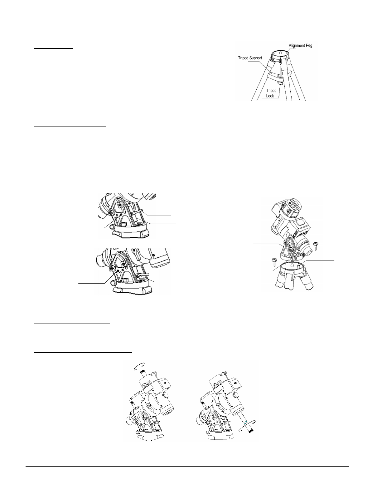
1. Setup tripod: Expand the tripod legs and lock the
Tripod Support so that the tripod legs stay open (Figure
1). Adjust the tripod height by unlocking and re-locking
the tripod legs to desired height. Position the tripod so
that the Alignment Peg faces south. (The Alignment
Peg may be moved to the opposite position if used
at latitude lower than 20º to avoid counterweights
hit the tripod leg )
Figure 1
2. Attach the iEQ30 Mount
: If the latitude is between 25º to 65º, set the Position Safety Pin at High Latitude Position,
as shown in Figure 2 (a). For latitude between 0º to 35º, set the Position Safety Pin at Low Latitude Position, as
shown in Figure 2 (b). Install the matching Latitude Adjustment Knob as well. The factory set default position is High
Latitude Position (25º ~ 65º).
Retract the Azimuth Adjustment Knobs (refer to Figure 3 in which is next to the Bubble Level Indicator) to allow
enough clearance for the Alignment Peg seating in the house. Unscrew 2 Azimuth Locking Screws. Put the mount
onto the tripod head with bubble level on top of the Alignment Peg (Figure 3). Put the Teflon washer and Azimuth
Locking Screws back and tighten them. Level the tripod base by adjusting individual leg. You may use the build-in
Bubble Level Indicator or an external torpedo level to check level.
(a)
High Lat. Position
(b)
Low Lat. Position
Figure 2
Lat. Adj. Lever
Lat. Adj. Knob (25º~65º)
Lat. Adj. Knob (0º~35º)
Bubble Level
Alignment Peg
Azi. Adj. Knob
Figure 3
3. Set the Location Latitude
: Unlock R.A. Clutch and adjust the mount upright. Tighten the R.A. Clutch. Unscrew four
Latitude Locking Screws. Turn the Latitude Adjustment Knob to set your current latitude (Figure 2), which is displayed
in Latitude Mark Window on the side of the mount. Using the Lever for a fine adjustment if needed.
4. Install Counterweight (CW) Shaft
: Unscrew the CW shaft from the top of the mount (Figure 4 left) and thread it into
the opening of the DEC axis (Figure 4 right).
Figure 4
iOptron Corp. | 6E Gill Street | Woburn, MA 01801 USA | (781) 569-0200 | Toll Free (866) 399-4587 | www.iOptron.com
2
Page 3

5. Connect Cables: Attach one end of a RJ-11 cable into the socket on the side of the DEC unit and the other end into
the DEC port located on R.A. unit. Using another RJ-11 cable to connect the hand controller to the HBX port located
on the R.A. unit. Plug 12V DC power supply into the POWER socket on R.A. unit. The power indicator on the R.A. unit
will be on when the power switch is turned on.
6. Polar Alignment:
In order for an equatorial mount to track properly, it has to be accurately polar aligned. The mount
has been set to face north (in Northern Hemisphere) as indicated in Step 1. The latitude has been roughly set, as
indicated in Step 3.
Take off the Polar Axis Cover and Polar Scope Cover. Look through the polar scope eyepiece to locate the Polaris. If
the hole is blacked by the DEC axle, use the ▲ or ▼ button on the hand controller to turn the DEC axle to unblock the
Polar Scope view. (You may use the number button to change the slewing speed. 9 for MAX speed). Loosen the two
Azimuth Locking Screws and adjust the Azimuth Adjustment Knobs to do a fine adjustment of the mount to center the
Polaris in the azimuth direction. Tighten the locking screws to secure the mount. Loosen four Latitude Locking Screws
on the side of the mount, turning the Latitude Adjustment Knob to adjust the latitude (altitude). Use the Lever for a fine
adjustment to center the Polaris along the latitude direction. Re-tighten the locking screws.
With iOptron’s AccuAligning
TM
Polar Scope and Quick Polar Alignment procedure, you can do a fast and accurate
polar alignment. Please refer to on-line full manual for more detailed description.
7. Install Counterweight
: iEQ30 comes with one 10lb (4.5kg) counterweight (CW) and an extension shaft. Use CW or
CW and extension shaft to balance your OTA (Optical Tube Assembly). Tighten the CW Locking Screw to hold the
CW in place. Tighten the CW Safety Screw.
8. Attach and Balance an OTA on the Mount
: After attaching an OTA and accessories to the mount, the iEQ30 must
be balanced in both R.A. and DEC to ensure minimum stress on the mount (such as gears and motors inside).
CAUTION: The telescope may swing when the R.A. or DEC clutch is released. Always hold on to the OTA
before you release the clutch to prevent it from swinging. It can cause personal injury or damage to the
equipment.
Balance the mount in DEC axis
Release the R.A. Clutch and rotate the R.A. axis to place the DEC axis in the horizontal position, as shown in Figure
5(a), and then tighten the R. A. Clutch. The OTA can be on either side. Then release the DEC Clutch and rotate the
OTA to a horizontal position as shown in Figure 5(b). If the OTA has a tendency to rotate about the DEC axis, you will
have to slide the OTA forward or backward to balance it in the horizontal position about the DEC axis. When the OTA
is balanced horizontally, tighten the DEC Clutch.
Balance the mount in R.A. axis
Release the R.A. Clutch. If the DEC axis stays in the horizontal position, as shown in Figure 5(a), it means the R.A.
axis is balanced. Otherwise, release the CW Locking Screw and move the CW as required to balance the R.A. axis.
Tighten the CW Locking Screw.
Figure 5
The iEQ30 also equipped with a electronic balance test system to assist you for precise balance of the mount. Please
refer to the full on-line manual for balance procedures/tips.
3
iOptron Corp. | 6E Gill Street | Woburn, MA 01801 USA | (781) 569-0200 | Toll Free (866) 399-4587 | www.iOptron.com
Page 4

9. Manual Operation of the Mount: Now you can observe astronomical objects using the arrow keys of a Go2Nova
hand controller. Flip the I/O switch on the telescope mount to turn on the mount. Use ►,◄,▼ or ▲ buttons to point
the telescope to the desired object. Use the number keys to change the slewing speed. Then press STOP/0 button to
start tracking.
10. Setup Controller:
The iEQ30 is equipped with a GPS receiver, which will receive
the local time, longitude and latitude information from satellites after the link is
established. However, In order to make hand control reflect your correct local time,
time zone information and Daylight Saving Time still need to be entered.
Turn on the power. Wait for controller lights on. Press the MENU button. Move the
cursor to “Set Up Controller” and press ENTER. Select “Set Up Time and Site”
and press ENTER. Enter the date and check if it is Daylight Saving Time using
arrow keys and number keys. Enter your time zone (add or subtract 60 minutes per
time zone) by entering minutes “behind” UT or “ahead of” UT, such as:
• Boston is 300 minutes “behind” UT
• Los Angeles is 480 minutes “behind” UT
Figure 6
• Rome is 60 minutes “ahead” of UT
• Sydney is 600 minutes “ahead” of UT
Move the cursor to the bottom of the screen to select Northern or Southern Hemisphere.
11. Adjust the Mount to Zero Position:
The Zero Position is the position where the counterweight shaft points to
ground, telescope is at the highest position with its axis parallel to the polar axis and the telescope is pointing to the
Celestial Pole. Loosen the DEC and R.A. Clutches to adjust the mount to the Zero Position. Tighten the screws after
each adjustment. Power cycle the hand controller.
12. Star Alignment:
Star alignment will improve the GOTO accuracy. From the main menu select “Align”. Select “One
Star Align” and press ENTER. Make sure your scope is at Zero Position. A list of align stars that are above the
horizon is computed based on your local time and location. Select a star and press ENTER. Use arrow buttons to
center the star in your eyepiece. Using number key to adjust the slew speed while centering the object. (1 for slowest,
9 for maximum). Press ENTER when finished. You may also choose two star or three star alignment to increase the
go to accuracy of the mount.
13. Go to an Object:
The mount is now ready to GOTO and tracking targets. Press MENU button, select “Select and
Slew” and press ENTER. Select a category (ex. “planets, sun, moon”). Then select an object (ex. “moon”). Then
press ENTER. The telescope will automatically slew to the object and lock on. It will automatically begin to track once
it locks on to the object.
14. Sync to Target:
One can also use this function to center and synchronize the object from Step 12 to improve the
local GOTO accuracy. This is more helpful if you are looking for some faint object near a bright star. A Select and
Slew has to be performed before “Sync to Target” operation. Press MENU button and select “Sync. To Target.”
Press ENTER. Next use the arrow keys to move object until it is centered in your eyepiece. Then press ENTER again
on the hand controller. “Sync to Target” is similar to one star alignment.
TM
iOptron Corp. | 6E Gill Street | Woburn, MA 01801 USA | (781) 569-0200 | Toll Free (866) 399-4587 | www.iOptron.com
4
Page 5

iEQ30 Assembly Term
DEC Unit
DEC Clutch
Dovetail Saddle
Dovetail Lock Screw
Polar Axis Cover
CW Shaft
CW Locking Screw
CW Shaft Extension
CW Safety Screw
Counterweight (CW)
DEC Axis
Tripod Head
Lat. Adj. Knob & Lever
Alignment Peg
R.A. Unit
R.A. Axis
Polar Scope Cover
Lat. Locking Screw (4)
Azi. Adj. Knob
Azi. Locking Screw (2)
Tripod Support
Tripod Leg
Tripod Lock
Leg Locking Lever
5
iOptron Corp. | 6E Gill Street | Woburn, MA 01801 USA | (781) 569-0200 | Toll Free (866) 399-4587 | www.iOptron.com
Page 6

IOPTRON TWO YEAR TELESCOPE, MOUNT, AND CONTROLLER WARRANTY
A. iOptron warrants your telescope, mount, or controller to be free from defects in materials and workmanship for two years. iOptron will repair or replace
such product or part which, upon inspection by iOptron, is found to be defective in materials or workmanship. As a condition to the obligation of iOptron
to repair or replace such product, the product must be returned to iOptron together with proof-of-purchase satisfactory to iOptron.
B. The Proper Return Merchant Authorization Number must be obtained from iOptron in advance of return. Call iOptron at 1.781.569.0200 to receive the
RMA number to be displayed on the outside of your shipping container.
All returns must be accompanied by a written statement stating the name, address, and daytime telephone number of the owner, together with a brief
description of any claimed defects. Parts or product for which replacement is made shall become the property of iOptron.
The customer shall be responsible for all costs of transportation and insurance, both to and from the factory of iOptron, and shall be required to prepay
such costs.
iOptron shall use reasonable efforts to repair or replace any telescope, mount, or controller covered by this warranty within thirty days of receipt. In the
event repair or replacement shall require more than thirty days, iOptron shall notify the customer accordingly. iOptron reserves the right to replace any
product which has been discontinued from its product line with a new product of comparable value and function.
This warranty shall be void and of no force of effect in the event a covered product has been modified in design or function, or subjected to abuse,
misuse, mishandling or unauthorized repair. Further, product malfunction or deterioration due to normal wear is not covered by this warranty.
IOPTRON DISCLAIMS ANY WARRANTIES, EXPRESS OR IMPLIED, WHETHER OF MERCHANTABILITY OF FITNESS FOR A PARTICULAR USE,
EXCEPT AS EXPRESSLY SET FORTH HERE. THE SOLE OBLIGATION OF IOPTRON UNDER THIS LIMITED WARRANTY SHALL BE TO REPAIR
OR REPLACE THE COVERED PRODUCT, IN ACCORDANCE WITH THE TERMS SET FORTH HERE. IOPTRON EXPRESSLY DISCLAIMS ANY
LOST PROFITS, GENERAL, SPECIAL, INDIRECT OR CONSEQUENTIAL DAMAGES WHICH MAY RESULT FROM BREACH OF ANY WARRANTY,
OR ARISING OUT OF THE USE OR INABILITY TO USE ANY IOPTRON PRODUCT. ANY WARRANTIES WHICH ARE IMPLIED AND WHICH
CANNOT BE DISCLAIMED SHALL BE LIMITED IN DURATION TO A TERM OF TWO YEARS FROM THE DATE OF ORIGINAL RETAIL PURCHASE.
Some states do not allow the exclusion or limitation of incidental or consequential damages or limitation on how long an implied warranty lasts, so the
above limitations and exclusions may not apply to you.
This warranty gives you specific legal rights, and you may also have other rights which vary from state to state.
iOptron reserves the right to modify or discontinue, without prior notice to you, any model or style telescope.
If warranty problems arise, or if you need assistance in using your telescope, mount, or controller contact:
iOptron Corporation
Customer Service Department
6F Gill Street
Woburn, MA 01801
www.ioptron.com
support@ioptron.com
Tel. (781)569-0200
Fax. (781)935-2860
Monday-Friday 9AM-5PM EST
NOTE: This warranty is valid to U.S.A. and Canadian customers who have purchased this product from an authorized iOptron dealer in the U.S.A. or
Canada or directly from iOptron. Warranty outside the U.S.A. and Canada is valid only to customers who purchased from an iOptron Distributor or
Authorized iOptron Dealer in the specific country. Please contact them for any warranty.
iOptron Corp. | 6E Gill Street | Woburn, MA 01801 USA | (781) 569-0200 | Toll Free (866) 399-4587 | www.iOptron.com
6
 Loading...