


iOptron®CEM40 Center-Balanced Equatorial Mount
Instruction Manual
Produ
ct CEM40 (#7400A series) and CEM40EC (#7400ECA series, as shown)
Please read the included CEM40 Quick Setup Guide (QSG) BEFORE taking the mount out of
the case!
This product is a precision instrument and uses a magnetic gear meshing mechanism. Please
read the included QSG before assembling the mount. Please read the entire Instruction
Manual before operating the mount.
You must hold the mount firmly when disengaging the gear switches. Otherwise personal
injury and/or equipment damage may occur. Any worm system damage due to improper
operation will not be covered by iOptron’s limited warranty.
If you have any questions please contact us at support@ioptron.com
WARNING!
NEVER USE A TELESCOPE TO LOOK AT THE SUN WITHOUT A PROPER FILTER!
Looking at or near the Sun will cause instant and irreversible damage to your eye.
Children should always have adult supervision while using a telescope.
2

Table of Contents
Table of Contents ........................................................................................................................................ 3
1. CEM40 Introduction ............................................................................................................................... 5
2. CEM40 Overview ................................................................................................................................... 6
2.1. Parts List .......................................................................................................................................... 6
2.2. Identification of Parts ....................................................................................................................... 7
2.3. CEM40 Mount Basic Cable Connection.......................................................................................... 7
2.4. CEM40 Cable Management ............................................................................................................. 8
2.5. Go2Nova® 8407+ Hand Controller ................................................................................................ 10
2.5.1. Key Description ...................................................................................................................... 10
2.5.2. The LCD Screen ..................................................................................................................... 11
2.6. Bench Testing the Mount ............................................................................................................... 12
3. CEM40 Mount Assembly ..................................................................................................................... 13
3.1. CEM40 Mount Assembly .............................................................................................................. 13
4. Getting Started ...................................................................................................................................... 23
4.1. Setting the Mount and Performing Polar Alignment ..................................................................... 23
4.2. Manual Operation of the Mount .................................................................................................... 23
4.3. One Star Alignment ....................................................................................................................... 23
4.4. GOTO the Moon and Other Objects .............................................................................................. 23
4.5. Star Identification Function ........................................................................................................... 23
4.6. Power-Down Memorization........................................................................................................... 24
4.7. Turning Off the Mount................................................................................................................... 24
4.8. Putting the Mount Back into the Carrying Case ............................................................................ 24
5. Complete Functions of Go2Nova® 8407+ Hand Controller ................................................................. 25
5.1. Select and Slew .............................................................................................................................. 25
5.1.1. Solar System ........................................................................................................................... 25
5.1.2. Deep Sky Objects .................................................................................................................... 25
5.1.3. Stars......................................................................................................................................... 25
5.1.4. Comets .................................................................................................................................... 25
5.1.5. Asteroids ................................................................................................................................. 25
5.1.6. Constellations .......................................................................................................................... 25
5.1.7. Custom Objects ....................................................................................................................... 25
5.1.8. Custom R.A. and DEC ............................................................................................................ 26
5.2. Sync to Target ................................................................................................................................ 26
5.3. Alignment ...................................................................................................................................... 26
5.3.1. Position of Polaris/SigmaOct .................................................................................................. 26
5.3.2. One Star Alignment ................................................................................................................ 26
5.3.3. Two Star Alignment ................................................................................................................ 26
5.3.4. Three Star Alignment .............................................................................................................. 27
5.3.5. Solar System Align ................................................................................................................. 27
5.3.6. Polar Iterate Align ................................................................................................................... 27
5.3.7. View Model Error ................................................................................................................... 27
5.3.8. Clear Alignment Data ............................................................................................................. 27
5.4. Settings ........................................................................................................................................... 27
5.4.1. Set Time and Site .................................................................................................................... 27
5.4.2. Beep Ettings ............................................................................................................................ 27
5.4.3. Display Settings ...................................................................................................................... 28
5.4.4. Set Guiding Rate ..................................................................................................................... 28
5.4.5. Set Tracking Rate .................................................................................................................... 29
3

5.4.6. Set Parking Position ................................................................................................................ 29
5.4.7. Meridian Treatment ................................................................................................................ 29
5.4.8. Set Altitude Limit ................................................................................................................... 29
5.4.9. Polar Scope Bright. ................................................................................................................. 29
5.4.10. HC Heating Switch ............................................................................................................... 29
5.4.11. Set RA Guiding ..................................................................................................................... 30
5.4.12. Language ............................................................................................................................... 30
5.5. Electric Focuser ............................................................................................................................. 30
5.6. PEC Option .................................................................................................................................... 30
5.6.1. PEC Playback.......................................................................................................................... 30
5.6.2. Record PEC ............................................................................................................................. 30
5.6.3. PEC Data Integrity .................................................................................................................. 30
5.7. Park Telescope ............................................................................................................................... 31
5.8. Edit User Objects ........................................................................................................................... 31
5.8.1. Enter a New Comet ................................................................................................................. 31
5.8.2. Enter Other Objects or Observation List ................................................................................ 31
5.9. Firmware Information .................................................................................................................... 32
5.10. Zero Position ................................................................................................................................ 32
5.10.1. Goto Zero Position ................................................................................................................ 32
5.10.2. Set Zero Position ................................................................................................................... 32
5.10.3. Search Zero Pos. ................................................................................................................... 32
6. Maintenance and Servicing ................................................................................................................... 33
6.1. Maintenance ................................................................................................................................... 33
6.2. iOptron Customer Service .............................................................................................................. 33
6.3. Product End of Life Disposal Instructions ..................................................................................... 33
6.4. Battery Replacement and Disposal Instructions ............................................................................ 33
Appendix A. Technical Specifications ..................................................................................................... 34
Appendix B. Go2Nova® 8407+ HC MENU STRUCTURE ..................................................................... 35
Appendix C. Polar Alignment using iPolar Electronic PolarScope .......................................................... 38
Appendix D. Gear Meshing Adjustment .................................................................................................. 44
Appendix E. Firmware Upgrade ............................................................................................................... 46
Appendix F. Computer Control a CEM40 Mount .................................................................................... 47
Appendix G. Go2Nova®Star List .............................................................................................................. 48
IOPTRON TWO YEAR TELESCOPE, MOUNT, AND CONTROLLER WARRANTY .................... 57
Ver. 1.1 2019.5
iOptron reserves the rights to revise this instruction without notice. Actual color/contents/design/function may differ from those described in this
instruction manual.
4

1. CEM40 Introduction
The iOptron® CEM40 mount is the next generation of center-balanced equatorial mounts. This mount is
incredibly eye-pleasing, and its beauty is found in more than its appearance. The functionality of the
mount is superb. Weighing in at only 15.8lbs., this mount can support a payload of up to 40lbs! That's
incredible!
This mount also has an integrated electronic polar finder scope known as the iPolar. This tool ensures
the accurate alignment of a telescope, even when the pole star is obscured. There are large levers on
the quick-lock drive engagement system; these large levers make it easy to snap the gears into place.
Make way for an innovative mount! This iOptron CEM40 mount uses iOptron's patent-pending
Universal Self-Centering Saddle (USCS). This saddle accommodates Losmandy and Vixen-style
dovetail plates. The CEM40 also uses iOptron's ultra-quiet, low-power consumption stepper motor drive
system, aiding the mount in providing precise tracking.
The iOptron CEM40 mount uses the Go2Nova® 8407 hand controller to navigate the night sky. This
incredible technology helps observers find celestial objects with the aid of the mount's 212,000+ object
database! For those looking for a telescope that has the capability of tracking and finding beautiful night
sky objects, this mount is a must have tool.
Features:
Unique design, Center-Balanced equatorial mount (CEM) for maximum payload and minimum
mount weight
Idea for both visual observation and astrophotography
Maximum payload of 40 lbs (18 kg) with the mount weight of only 15.8 lbs (7.2 kg)
All metal, CNC machined with red/black anodized
Easy to use quick-lock gear clutches
Integrated iPolar
Low periodic error: <±7 arc seconds for CEM40, < 0.25 arcsec RMS for CEM40EC
Permanent periodic error correction (PPEC) or Real-time periodic error correction (for
CEM40EC)
Precision stepper motor for precise GOTO and accurate tracking
Go2Nova® 8407+ controller with Advanced GOTONOVA
heater
Integrated ST-4 autoguiding port
32-channel Global Positioning System (GPS)
USB communication port
Cable management system
New, patent-pending iOptron universal saddle
Standard 1.5 inch heavy-duty stainless steel tripod (5kg), optional 2” tripod or Tri-pier
Optional WiFi module (iStarFi, #7434) for mount control via SmartPhone/Tablet/Computer
TM
electronic polar finder
®
GOTO Technology with built-in
5

2. CEM40 Overview
2.1. Parts List1
SHIPPING CONTENTS
Your new CEM40 mount comes in two shipping boxes. One box contains either a CEM40
(#7400A) or CEM40EC (#7400ECA) mount head, hand controller, counterweight shaft, and accessories.
The other box contains a 1.5” tripod and a 10lbs (4.5kg) counterweight. The contents are:
iOptron
mount (#7400ECA, high precision model with red gear switches)
Go2Nova
One 10lbs (4.5 kg) counterweight
Stainless steel counterweight shaft
Internal iPolar electronic polar scope
CEM40 GPS module
AC adapter (100V-240V)
2X coiled control Cable (6P6C RJ11 to RJ11, straight wired)
Serial cable (RS232 to RJ9)
USB cable
Aluminum carrying case (for CEM40EC)
1.5” tripod
Quick Start Guide
®
CEM40 telescope mount (#7400A, with black gear switches) or iOptron® CEM40EC
®
8407 Hand Controller
OPTIONAL PARTS
2” tripod
Tri-Pier (#8034)
iStarFi wireless adapter (#7434)
USB to RS232 Converter with FTDI chipset (#8435)
ONLINE RESOURCES (click on the “Support” menu at www.iOptron.com)
Quick Start Guide
Instructional manual
Tips for set up
Hand controller and mount firmware upgrades (check online for latest version)
iOptron ASCOM driver
Reviews and feedback from other customers
Accessories
1
US market only. Actual contents, design and function may vary.
6
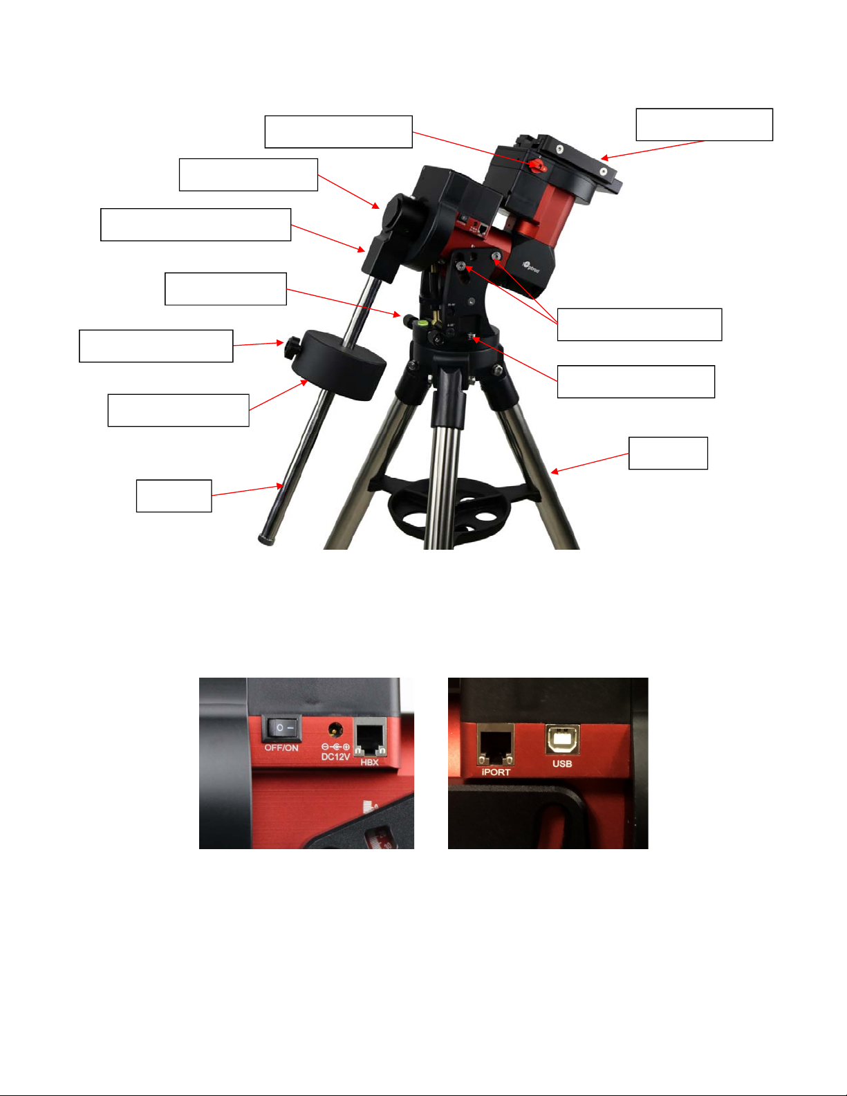
2.2. Identification of Parts
Polaraxiscover
CWmountinghousing
Az.adj.knob
CWlockingscrew
Counterweight
CWbar
DECgearswitch
Dovetailsaddle
Lat.lockingscrews
Azi.lockingscrew
Tripod
Figure 1.CEM40 mount assembly
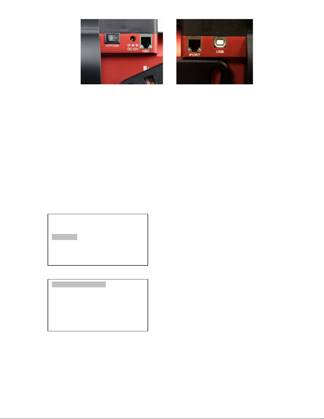
2.3. CEM40 Mount Basic Cable Connection
Figure 2. Ports on a CEM40 mount
OFF/ON (O/I): Power Switch
DC 12V: DC power socket to power the mount (2.1mmX5.5mm, center positive)
HBX (Hand Box): For connecting to an 8407 Hand Controller
iPORT: Auxiliary port for connecting to other iOptron accessories, such as a GPS receiver,
an iStarFi WiFi adapter, an electronic focuser or for observatory dome control. DO NOT plug
ST-4 guiding camera cable into this port, It will damage the guide camera electronics.
7
USB: USB port for mount-computer control and firmware upgrade
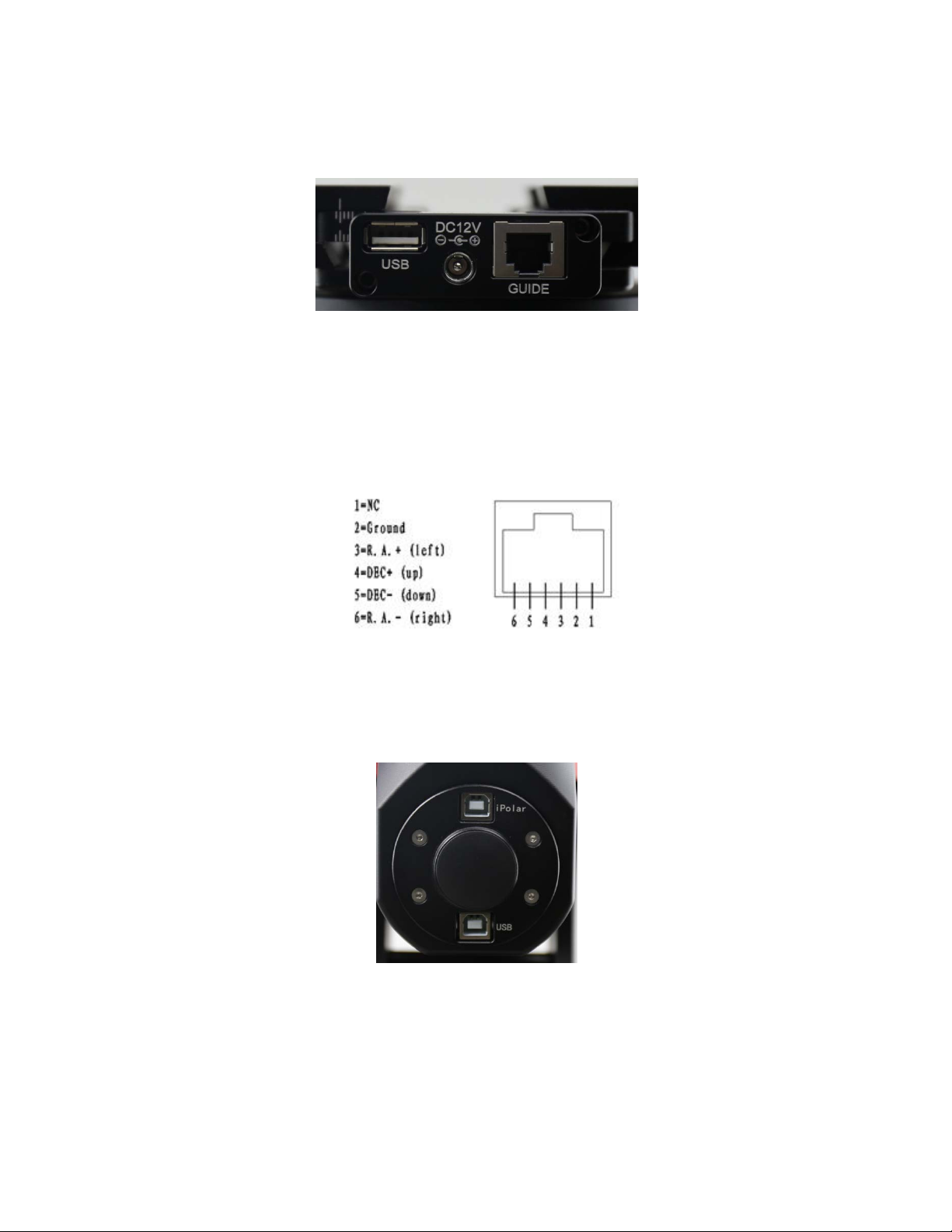
2.4. CEM40 Cable Management
The CEM40 mount has a pre-wired Cable Management Panel (CMP). As shown in Figure 3, the Cable
Management Panel has the following connections:
Figure 3.Cable management panel
1X USB 2.0 ports with standard type A connectors for connecting accessory;
1X DC12V power outlet (2.1mmX5.5mm, center positive, max. current 3A) for powering
accessories such as CCD cameras, filter wheels, or electric focusers;
GUIDE: ST-4 compatible autoguiding port. The wiring is shown in Figure 4
Figure 4. ST-4 Compatible Guiding Port Wiring
The USB-A port on the Cable Management Panel are connected to the USB-B connector on Input
Panel, as shown in Figure 5.
Figure 5. Input panel
1x USB 2.0 port with a standard type B connector
1X iPolar USB port for internal iPolar electronic polar scope connection
There is a hole on dovetail saddle that allows a user to run his own cables down through the mount, to
either the back of RA axle or bottom of the DEC axle.
8

Figure 6. Openings for custom cable management
The CMP can also be moved from the back of the dovetail saddle to the front.
Figure 7. Top of the dovetail saddle
CMP
9
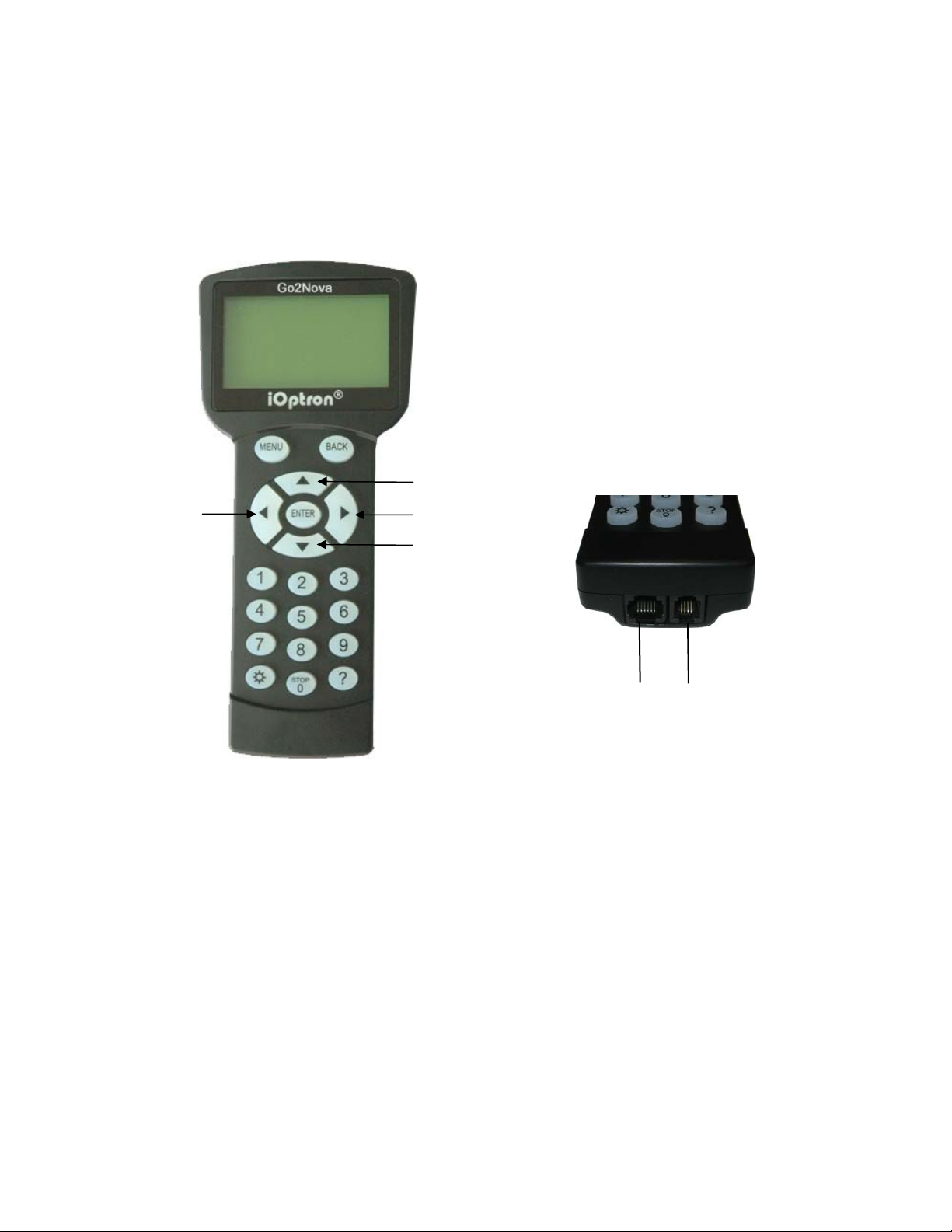
2.5. Go2Nova® 8407+ Hand Controller
The Go2Nova® 8407+ hand controller (HC) shown in Figure 8 is the standard controller used on the
CEM40 mount. It has an integrated heater that ensures the LCD display will work at the temperature as
low as -20ºC(-4ºF). It has a large LCD screen, function, direction, and number keys on the front; a red
LED reading light on the back; and a HBX (6-pin) and a RS232 serial port (4-pin) at the bottom.
The CEM40 mount can be operated without the hand controller attached if it is controlled via a
SmartPhone/Tablet/Computer.
DEC+
R.A.+
R.A.-
DEC-
HBX
Port
Serial
Port
Figure 8. Go2Nova® 8407+ hand controller
2.5.1. Key Description
MENU Key: Press “MENU” to enter the Main Menu.
BACK Key: Move back to the previous screen, or end/cancel current operation, such as
slewing.
ENTER Key: Confirm an input, go to the next menu, select a choice, or slew the telescope to
a selected object.
Arrow (▲▼◄►) Keys: The arrow keys are used to control the movement of DEC and R.A.
axes. Press and hold ▲(DEC+),▼(DEC-) buttons to move a telescope along the DEC
direction, ◄(R.A.+), ►(R.A.-) to move a telescope along the R.A. direction. They are also
used to browse the menu or move the cursor while in the menu. Press and holding an arrow
key for a fast scrolling.
Number Keys: Input numerical values. Also used to adjust speeds (1: 1X; 2: 2X; 3: 8X; 4:
16X; 5: 64X; 6: 128X; 7: 256X; 8: 512X; 9: MAX)
Light Key(☼): Turns on/off the red LED reading light on the back of the controller.
Help (?) Key: Identify and display bright stars or objects that the telescope is pointing to.
10

STOP/0 Key: Stop the mount during GOTO. Also toggling between starting and stopping
tracking.
HBX (Handbox) port: connect the HC to the CEM40 mount using a 6P6C RJ11 cable.
Serial port: connect the HC to a computer via a RS232 to 4P4C RJ9 cable. The pin-out of the
serial port is shown in Figure 9.
Figure 9. Serial port pin-out on an 8407+ hand controller
2.5.2. The LCD Screen
The 8407+ HC has a large 8-line, 21-character per line, LCD screen which displays information on the
status of the mount as shown in Figure 10.The user interface is simple and easy to operate.
Figure 10. 8407+ HC LCD Information Screen
1. Target Name/Mount Position: displays the name of the target that telescope is currently pointed to
or the current mount position.
Zero Position: The reference position for GOTO. The mount can move to Zero Position
using “Goto Zero Position” or “Search Zero Position” command;
User Position: The mount is pointed to a user defined position, which could be a particular
celestial object or simply a position determined by pressing an arrow key;
An object name, such as “Mercury” or “Andromeda Galaxy”: Name of the star or celestial
object that the mount is currently slewing to or tracking.
2. Target R.A.: Right Ascension (R.A.) of the target object.
3. Target Declination: Declination (DEC) of the target object.
4. Right Ascension: Current R.A. of the telescope.
5. Declination: Current DEC of the telescope.
6. Altitude: Altitude of the telescope (degrees vertical from the local horizon - zenith is 90º).
7. Azimuth: Azimuth of the telescope (north is 0º, east is 90º, south is 180º, and west is 270º).
11
8. Local Date and Time: displays the local time in a format of YY-MM-DD HH:MM:SS.
9. Mount Status: Displays the current operational status of the mount.
Stop: mount is not moving;
Slew: mount is moving with an arrow key is pressed or a GOTO command, such as “Select
and Slew” or “Goto Zero Position”;
Tracking: mount is at a tracking status.
10. GPS status: When the power is turned on, the initial GPS status will be “GPS ON”, which means
that the mount is connected to its GPS receiver and is seeking a satellite signal. When the GPS
receiver finds the satellites and receives the GPS signal the status will change to “GPS OK”.
11. PEC status: Display of “PEC” here Indicates the Periodic Error Correction playback is turned on.
Default is off.
12. Tracking speed: Displays the current tracking rate of the mount.
SDRL: mount is tracking at sidereal speed;
Solar: mount is tracking at solar speed;
Lunar: mount is tracking at lunar speed;
King: mount is tracking at king speed;
CSTM: mount is tracking at a custom, user-defined speed.
13. Slew speed: The mount has 9 slew speeds: 1X, 2X, 8X, 16X, 64X, 128X, 256X, 512X, MAX
(~4º/sec).
14. Operation Mode: EQ indicates that the mount is operating in an equatorial mode.
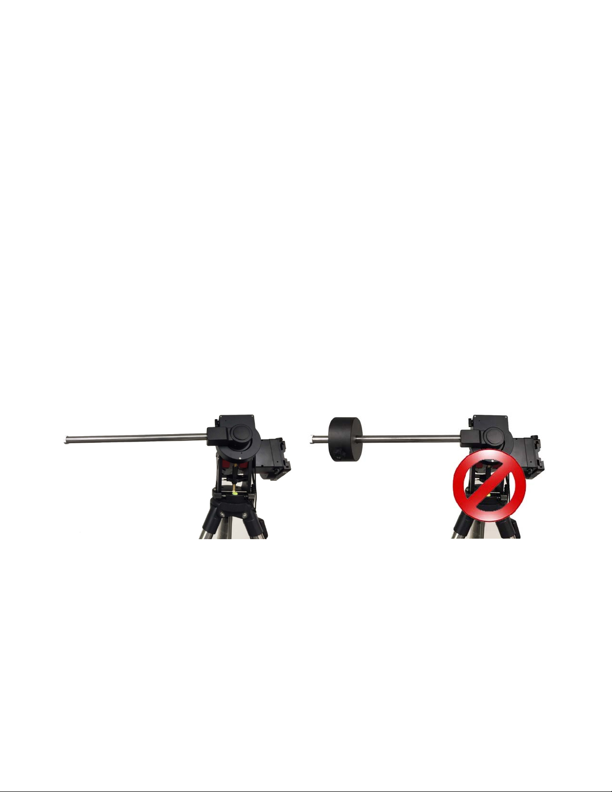
2.6. Bench Testing the Mount
The counterweight shaft is designed to counter balance the mount’s own weight. It is recommended
that the CW shaft is installed when testing the mount’s function, as shown in Figure 11.
Figure 11. Setup for initial mount testing
Slewing the mount without the CW shaft installed is not recommended.
NEVER operate the mount with only the counterweight or OTA on it
precision engineering of the mount drive system.
. It may damage the
12
3. CEM40 Mount Assembly
3.1. CEM40 Mount Assembly
NOTE: The CEM40 mount is a precision astronomical instrument. It is highly recommended that
you read this entire manual and become familiar with the nomenclature and function of all
components before starting assembly.
WARNING: DO NOT rock the counterweight shaft rigorously. This may damage the
worm/drive gear system and such damage will not be covered by warranty.
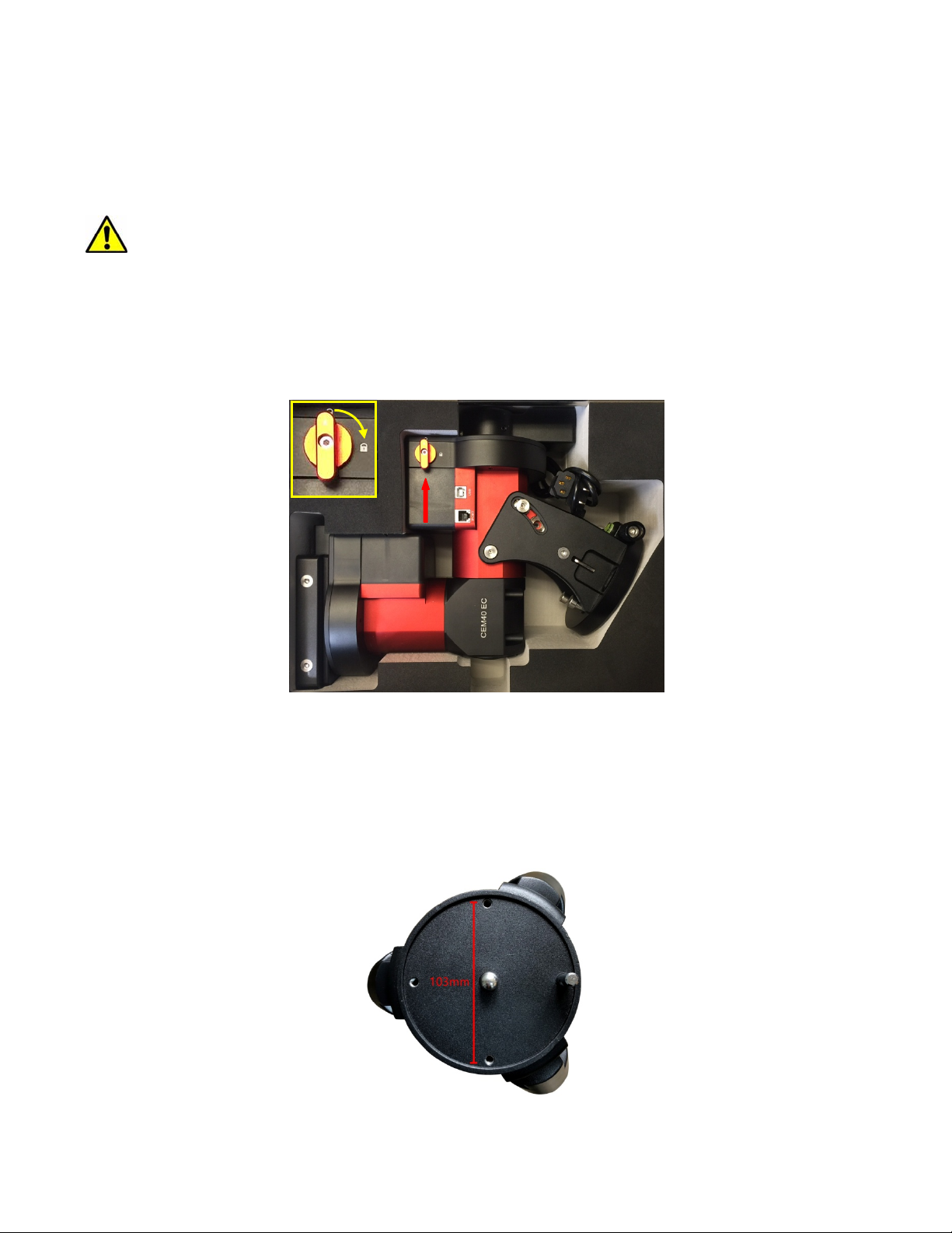
STEP 1. Remove the mount head from package
The mount head is shipped with the R.A. Gear Switch unlocked to protect the worm/gear system. Turn
the Gear Switch 90° to lock the R.A. gear system before removing it from the box.
Figure 12. Mount in a hard case
STEP 2. Set up tripod
The tripod top is 120 mm in diameter with 2x M6 holes 103 mm apart for mounting. Two additional M6
holes are for the Alignment Peg (the one on top of a leg is for high latitude use; the other one between
two legs is for low latitudes). Thread the Alignment Peg into the correct M6 hole. Insert the Accessory
Tray through the center rod and secure the setup by tightening Locking Knob from underneath.
Figure 13. Tripod top
13
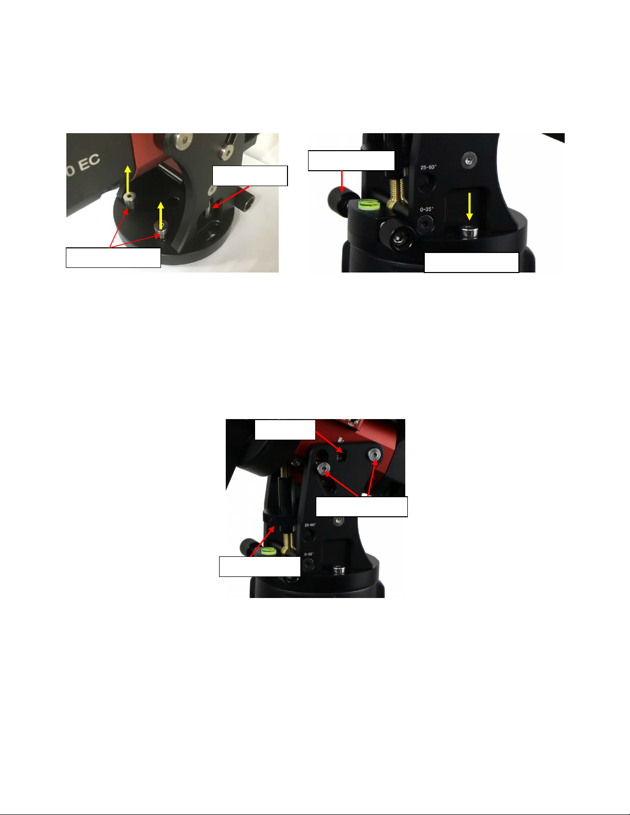
STEP 3. Attach the mount
Retract the 2x Azimuth (Azi) Adjustment Screws from both sides to leave ample space for the
alignment peg to fit in between the 2 Azi Adjustment Screws. Remove the 2x Azi Locking Screws, with
washers, from the mount base. Secure the mount head by tightening the Azi Locking Screws into the
M6 holes on the tripod. An Allen wrench is included for convenience.
Azi. Adj. Screw
Allen wrench
Azi. Lock Screw
Azi. Lock Screw
Figure 14. Attach the mount
Level the mount by adjusting the tripod legs. Use the build-in Bubble Level Indicator or an external
leveler for this purpose.
STEP 4. Adjust latitude
Without any payload, slightly loosen the 4x Latitude Locking Screws. Use the Latitude Adjustment
Knob to set the correct latitude value, as displayed in the Latitude Mark Window. Insert the Allen
wrench into the Latitude Adjustment Knob for more turning torque.
Lat. Mark
Lat. Lock Screw
Lat. Adj. Knob
Figure 15. Adjust latitude
Two latitude ranges, 0~35° and 25~60°, can be set up for the mount head. To change the latitude
range from one to the other, both the Latitude Position Bolt and the Latitude Locking Screws need to
be moved to the correct locations (see photos below).
Loosen the Latitude Locking Screws just enough to adjust the latitude setting to 30°. Move the Latitude
Locking Screws with washers (one on each side) to the new locations revealed, do not tighten them just
yet.
14
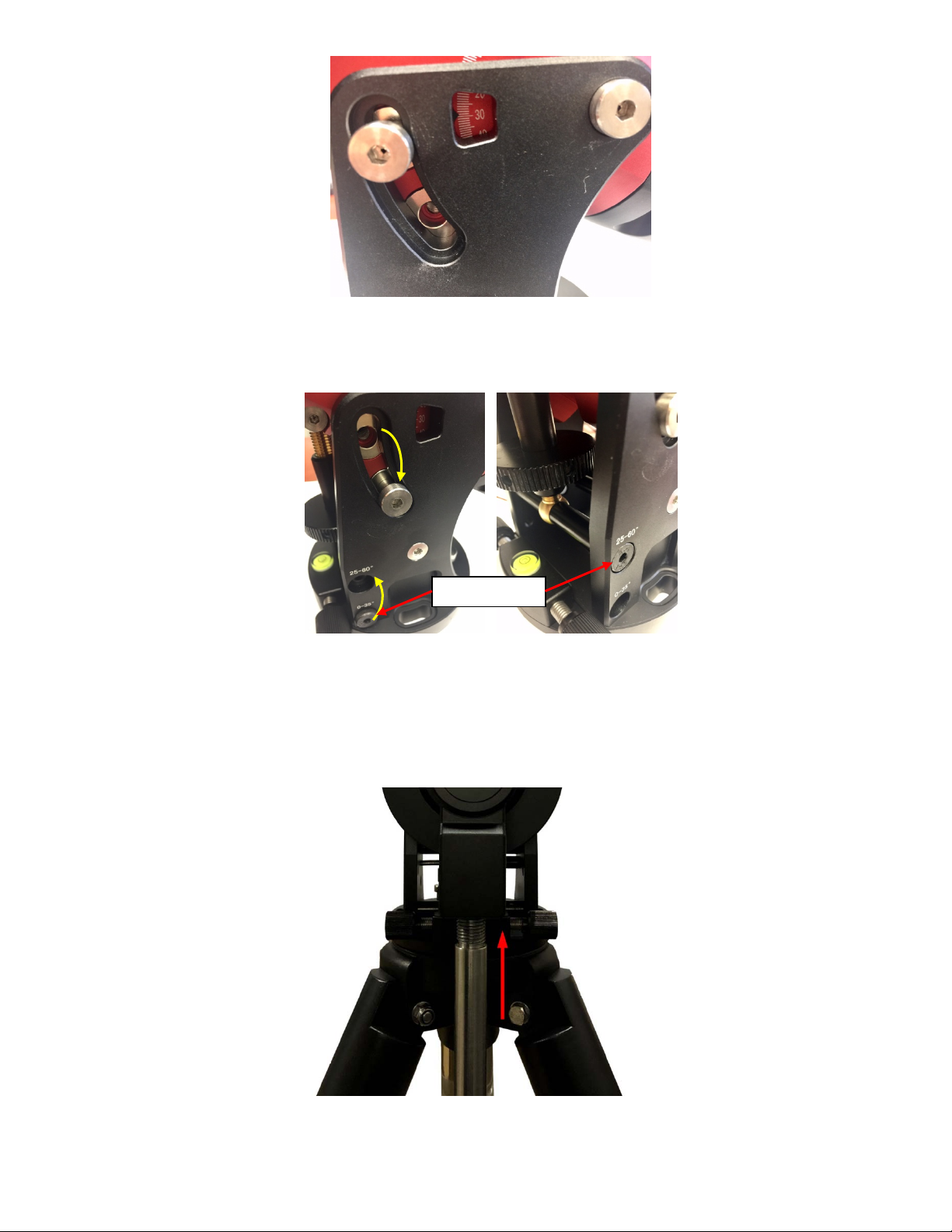
Figure 16. Latitude mark window
Unthread and remove the Position Bolt to its new location. Adjust the Latitude Adjustment Knob while
holding the brass eyebolt until it lines up with the Position Bolt. Secure the Latitude Position Bolt.
Position Bolt
Figure 17. Change latitude range
STEP 5. Install Counterweight (CW) Shaft
Thread the CW shaft into the CW shaft mounting house. For low latitudes (<10°), a special CW
mounting house is needed. (Contact iOptron for more information)
Figure 18. Install CW shaft
15
STEP 6. Install Counterweight(s)
Before putting on CW, make sure the mount is at its zero position, i.e., CW shaft points to the ground.
Disengage the R.A. Gear Switch to set the R.A. axis free before loading the CW. Remove the CW
Safety Cap at the end of CW Shaft. Glide the CW over the shaft with the larger hole opening facing
down. Tighten the CW Locking Screw to hold the CW in place. Place the Safety Cap back onto the
shaft. Move the CW to the bottom of the shaft and tighten the CW locking Screw.
Figure 19. Install Counterweight
You may need more CW for heavier payloads, or a smaller CW for lighter scopes.
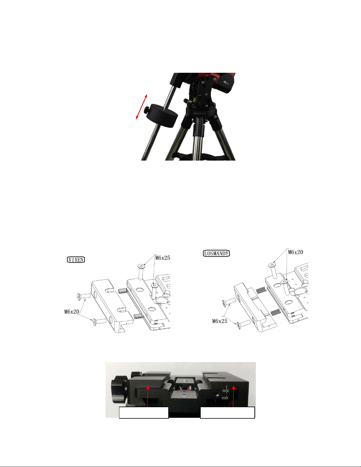
STEP 7. Install Telescope
CEM40 is equipped with a 5” iOptron Universal Saddle. It can receive either a Vixen or a Losmandy-D
plate by flipping both Stationary Block and Locking Block. This unique adjustable dovetail saddle
enables the scope to sit at the center of the saddle.
The following graphics show how to change the dovetail saddle to fit either Vixen or Losmandy plate.
Figure 20. Switch the dovetail saddle from Vixen to Losmandy (Stationary Side)
Please Note that two sets of screws have different lengths and must swap location.
Stationary Block Lockingy Block
Figure 21. Vixen dovetail saddle
16
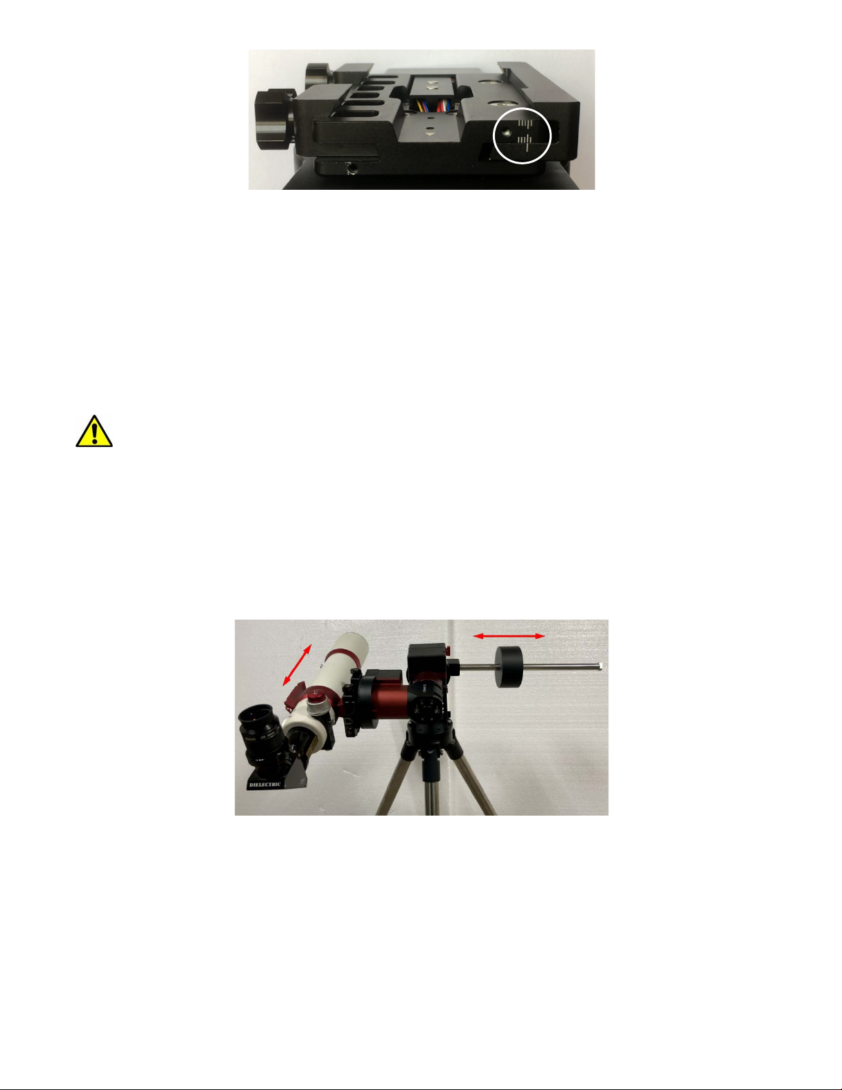
Figure 22. Losmandy dovetail saddle
After switch the Stationary and Locking Blocks, make sure that the alignment mark on the Stationary
Block is aligned to one of the position marks on the saddle plate. If you have a wider dovetail plate,
move the Stationary Block to an outside mark. For a narrow plate, move the Stationary Block to an
inside mark. The marks are located on both end of the saddle plate.
STEP 8. Balance the Payload
After attaching the scope and accessories, the mount head assembly must be balanced in both DEC
and RA axes to ensure minimum stresses on the mount driving mechanism.
CAUTION: The telescope may swing freely when the R.A. or DEC Gear Switch is
disengaged. Always hold on to the mount and/or telescope assembly before releasing
the Gear Switches to prevent it from swinging, which can cause personal injuries and/or
equipment damages.
Set the mount at Zero Position. Disengage both RA and DEC gear switches and move the mount to
horizontal position to check balance. Return to Zero Position for balance adjustment. Balance the DEC
axis by moving the scope with accessories back and forth in the mount saddle or within the scope
mounting rings. Balance the assembly in R.A. axis by moving CW along its shaft. Repeat the process
until both DEC and RA axes are balanced.
CAUTION: The balancing process MUST be done with Gear Switch at the total disengaged
position! Otherwise it might damage the worm system.
Figure 23. Balance a mount
Return the mount to Zero Position after balancing and engage gear switches.
STEP 9. Connect Cables
Plug in a 12V DC power supply to the DC12V POWER socket. Connect the Go2Nova
Controller to the HBX port on the mount side panel.
®
8407 Hand
17
j
Figure 24. Ports for cables
Plug GPS module into the iPORT with coiled cable. When powering on, GPS ON sign should be
displayed at the upper right corner of the hand controller. If you want to use the iPort for another
accessory, such as WIFI adapter (iStarFi #7434), or electronic focuser (#8451/#8452), you may
disconnect the GPS module after it picks up satellites signals and displays GPS OK on hand controller.
(It takes about 1 to 2 minutes in normal conditions).
STEP 10. Setting up the Hand Controller
The CEM40 mount is equipped with a GPS receiver which will receive the time, longitude and latitude
information for your current location from satellites after a link is established. However, there are still
some parameters which need to be entered to reflect your location, such as time zone information and
whether daylight saving time is currently in effect. This information will be stored in the hand controller
memory along with longitude and latitude coordinates until they need to be updated.
A clear sky and open space outside is needed for the GPS to establish a link with the satellites.
To set up the controller, press MENU =>“Settings”:
Select and Slew
Sync. to Target
Alignment
Settings
Electric Focuser
PEC Options
Park Telescope
Edit User Ob
Press ENTER and select “Set Time and Site”
ects
Set Time and Site
Beep Settings
Display Settings
Set Guiding Rate
Set Tracking Rate
Set Parking Position
Meridian Treatment
Set Altitude Limit
Press ENTER. A time and site information screen will be displayed:
18

Daylight Saving Time Y
UTC -300 Minute(s)
2019-03-09 10:19:18
Longitude:W071d08m50s
Latitude: N42d30m32s
Northern Hemisphere
Set Local Time
The time will be updated automatically when the GPS receiver has established its link to the satellites.
In the event that the GPS module is unable to establish a link, local time can be entered manually. Use
the ◄ or ► key to move the cursor _ and use the number keys to change the numbers. Use the ▲ or
▼ button to toggle between “Y” and “N” for Daylight Saving Time, or “+” and “-“ for UTC (Coordinated
Universal Time) setting. Hold the arrow key to fast forward or rewind the cursor.
In order to make the Hand Controller reflect your correct local time, time zone information has to be
entered. Press the ◄ or ► key, move the cursor to the third line “UTC -300 Minute(s)” to set the time
zone information (add or subtract 60 minutes per time zone). For example:
Boston is “UTC -300 minutes”
Los Angeles is “UTC -480 minutes”
Rome is “UTC +60 minutes”
Beijing is “UTC +480 minutes”
Sydney is “UTC +600 minutes”
All the time zones in North America are “UTC –“, as shown in the following table, so ensure the display
shows “UTC -” instead of “UTC +”.
Time Zone Hawaii Alaska Pacific Mountain Central Eastern
Hour behind UT -10 -9 -8 -7 -6 -5
Enter UTC -600 -540 -480 -420 -360 -300
To adjust minutes, move the cursor to each digit and use the number keys to input the number directly.
Use ▲ or ▼ key to toggle between “+” and “-”. When the time one information entered is correct, press
ENTER and go back to the previous screen. Note that fractional time zones can be entered.
Do not manually add or subtract an hour from displayed time to reflect Daylight Saving Time (DST).
Only select “Y” after DST begins.
For other parts of the world you can find your “time zone” information from internet.
Set Observation Site Coordinates
The fifth and sixth lines display the longitude and latitude coordinates, respectively. The longitude and
latitude coordinates will be automatically updated when the GPS picks up a satellite signal. “W/E”
means Western/Eastern Hemisphere; “N/S” means Northern/Southern Hemisphere; “d” means degree;
“m” means minute; and “s” means second.
If, for any reason, your GPS does not pick up the satellite signal, you can manually enter your longitude
and latitude coordinates. Press the ◄ or ► key to move the cursor, use the ▲ or ▼ key to toggle
between “W” and “E”, and “N” and “S”, and use the number keys to change the numbers. It is always a
good idea to do your homework and get longitude and latitude coordinates before traveling to a new
observation site.
The site coordinates information can be found from your smart phone, GPS receiver or via the internet.
Site information in decimal format can be converted into d:m:s format by multiplying the decimal
19

numbers by 60. For example, N47.53 can be changed to N47º31'48”: 47.53º = 47º +0.53º,
0.53º=0.53x60'=31.8', 0.8'=0.8x60"=48". Therefore, 47.53º=47º31'48" or 47d31m48s.
Select N/S Hemisphere
The northern/southern hemisphere will be determined by your latitude coordinate, with one exception. If
your are near the equator (within +/- 10°), you can choose your own N/S setting.
If the polar axis is aligned to the North Celestial Pole, then set the mount to Northern Hemisphere. If the
polar axis is pointing to the South Celestial Pole, set the mount to Southern Hemisphere. Press the ◄
or ► key to move the cursor and use the ▲ or ▼ key to toggle between “Northern Hemisphere” and
“Southern Hemisphere”.
The time and site information will be stored inside the hand controller’s memory chip. If you are not
traveling to another observation site, they do not need to be changed.
Check the Hand Controller Battery
The hand controller has a real time clock (RTC) which should display the correct time every time the
mount is turned on. If the time is incorrect, please check the battery inside the hand controller and
replace it if required. The battery is a 3V, CR1220 button battery.
STEP 11. Set the Zero Position
Zero Position is the mount starting reference point which ensures the GOTO performance. Press
MENU => “Zero Position” => “Search Zero Position” to let the mount search the Zero Position.
Follow the instruction on hand controller display to adjust the Zero Position if RA or DEC is not aligned.
Or press MENU => “Zero Position” => “Set Zero Position”, to manually set the mount to Zero
Position. Loosen the DEC and R.A. Gear Switches in turn to adjust the mount to the Zero Position.
Engage the clutches after each adjustment.
STEP 12. Perform Polar Alignment
Polar Alignment with iPolar Electronic Polar Scope
CEM40 & CEM40EC are equipped with an iPolar
TM
electronic polar scope. To perform polar alignment,
please refer to Appendix C. It is simple and fast, even the pole star or part of the sky is blocked. Steps
are briefly outlined below:
Download and install iPolar Software (first time use)
Connect a USB cable between the iPolar port on the mount and a computer USB port
Calibrate the iPolar Rotation Center (first time use)
Click Connect and start polar alignment by following on screen instructions
Quick Polar Alignment
TM
If the mount equipped with a AccuAlign
optical polar scope, you can use ths Quick Polar Alignment
procedure to perform the polar alignment. One of the CEM40’s unique features is that the polar scope
can be used at anytime as it is not blocked by DEC axle as is the case in a German Equatorial Mount.
This makes it possible to adjust the polar alignment while the mount is tracking.
As indicated in Figure 25, the Polar Scope reticle has been divided into 12 hours along the angular
direction with 20-minute tics. There are 6 concentric circles in 2 groups of 3 marked from 36’ to 44’ and
60’ to 70’, respectively. The 36’ to 44’ concentric circles are used for polar alignment in the Northern
Hemisphere using Polaris, while the 60’ to 70’ circles are used for polar alignment in Southern
Hemisphere using Sigma Octantis.
20

Figure 25. Polar Scope
Figure 26. Connect polar scope LED
To perform the polar alignment:
(1) Level the CEM40 mount and set it to the Zero Position. Make sure the telescope optical axis is
parallel to the polar axis (R.A. axis) of the mount. If using a finder scope, adjust it to be parallel to
the telescope optical axis.
(2) Remove both the Polar Axis Cover and Polar Scope Cover. Thread the polar scope LED to the
Polar Scope. Connect one end of the polar scope power cable to the illumination LED and the
other end to the DC12V output located on DEC Cable Management Panel (Figure 26).
(3) Turn the mount power on. Use the Hand Controller (“Settings” => “Polar Scope Brightness”) to
set the illumination intensity.
(4) Adjust the polar scope dial to rotate the 12 o’clock at the top.
(5) Use the Hand Controller (MENU => “Alignment” => “Position of Polaris/SigmaOct”) to display
the current position of Polaris on the LCD screen, as indicated in the left side of the figure below.
For example, June 22, 2014, 20:19:42 in Boston, US (long. W71°08’50” and lat. N42°30’32”, UTC 300 min,) the Polaris Position is 0h45.8m and 40.4m.
(a) (b)
Figure 27. Polaris Position shown on HC (a) and where to put on polar scope reticle (b)
(6) Look through the polar scope to find the Polaris. Use the Azimuth and Latitude Adjustment Knobs
to adjust the mount in both directions and put the Polaris in the same position on the Polar Scope
reticle as indicated on the HC display screen. In this case, Polaris will be located at a radius of 41.5
minutes and an angle of 1 hour 26.8 minutes, as shown In Figure 27 (b).
NOTE: If you are located in the Southern Hemisphere, Sigma Octantis will be chosen for Polar
Alignment.
21

BrightStar Polar Alignment
If you mount does not have a iPolar installed, or the pole star is not in sight, you may use two bright
stars with Polar Iterate Align to do the polar alignment.
(1) Level the mount and set it to the Zero Position. Align the telescope to the R.A. axis of the
mount. If a finder scope is used, adjust it to be parallel to the telescope optical axis.
(2) Use the HC (MENU => “Alignment” => “Polar Iterate Align”) to display the azimuth and
altitude position of several bright stars near the meridian. Select one that is visible at a high
altitude as Alignment Star A. Follow the HC instruction to move Alignment Star A to the
center of the eyepiece using a combination of the Latitude Adjustment Knob and the “◄” or
“►” buttons. Press ENTER to confirm when the star is centered. Next, select a bright star
that is close to the horizon as Alignment Star B. Center it using the Azimuth Adjustment
Knob and the “◄” or “►” button (the “▲” and “▼” buttons are not used here). Press ENTER
to confirm the settings.
(3) The telescope will now slew back to Alignment Star A. Repeat the steps above. The iteration
can be stopped when it is determined that the alignment error has been minimized. Press
the BACK button to exit the alignment procedure.
NOTE: It is highly recommended to use an eyepiece with an illuminated crosshair for accurate
centering.
NOTE: The movement of the alignment star in your eyepiece may not be perpendicular depending on
its location in the sky.
STEP 13. Returning the Mount to Zero Position
After polar alignment and balancing OTA, return the mount to the Zero Position. Please check the zero
position after set up the mount or firmware update.
22

4. Getting Started
In order to experience the full GOTO capability of GOTONOVA® technology it is very important to set
up the mount correctly before observation.
4.1. Setting the Mount and Performing Polar Alignment
Assemble your CEM40 mount according to Section 3.1. Make sure the mount is leveled. Turn the
mount power switch on. When the GPS receiver is connected to satellites, the hand controller LCD will
display GPS OK and the mount will have the correct time and site information (this can also be entered
manually as previously described). Mount an OTA and accessories, and carefully balance the mount on
both R.A. and DEC axes. Perform the polar alignment.
After the mount is powered on, perform MENU => “Zero Position” => “Goto Zero Position” to check
the Zero Position, i.e. with the counterweight shaft pointing to ground, OTA at the highest position with
its axis parallel to the polar axis and the telescope pointing to the Celestial Pole. If the mount is not at
the Zero Position, you may perform Search Zero Position or Set Zero Position to set the Zero
Position.
4.2. Manual Operation of the Mount
The mount can now be used to observe astronomical objects using the HC. Use the arrow keys (►, ◄,
▼, and ▲) to point the telescope to the desired part of the sky. Use the number keys to change the
slewing speed. Press the STOP/0 button to start tracking.
4.3. One Star Alignment
After the mount set up, perform a “One Star Align” to correct the Zero Position discrepancy, or linear
error.
Press MENU => “Alignment” => “One Star Align” to perform “One Star Align.” The hand controller
will display an alignment star. Select a different star using the ▲ or ▼ keys. Then press ENTER. After
the mount slews to the target, use the arrow keys to center it in your eyepiece. Then press ENTER.
(More details on the alignment function are given in section 5.3)
4.4. GOTO the Moon and Other Objects
Now the mount is ready for GOTO operation which, using advanced GOTONOVA® technology, will
automatically slew to, and track, a huge range of celestial targets. We will use the Moon as an example.
Press MENU => “Select and Slew”. Select a category, in this example “Solar System”, and then
select an object of interest, in this case “Moon”. Press ENTER and the telescope will slew to the moon
and automatically start tracking. If the target is not centered in your eyepiece, use the arrow keys to
center it. Then use MENU => “Sync to Target” for better performance.
4.5. Star Identification Function
The 8407+ hand controller has a star identification function. After setting the correct local time and
location and completing polar alignment, slew the telescope to a bright star manually or using the
GOTO function. Press the Help(?) key to identify the star that the telescope is pointing to, as well as
nearby bright stars if there is any.
23

4.6. Power-Down Memorization
The CEM40 mount can memorize its R.A. and DEC positions if the mount power is lost during
operation, even during high speed slewing. After the power is back, just do a Select and Slew to the
same star when the power is lost. The mount will continue to track the star.
4.7. Turning Off the Mount
When you have finished your observation, simply turn the mount power off and disassemble the mount
and tripod.
If the mount is set up on a pier or inside an observatory, it is recommended that you return the mount to
the Zero Position or park the telescope. This will ensure that there is no need for you to perform the
initial setup again when you power on the mount subsequently so long as the mount has not been
moved from the parked position.
4.8. Putting the Mount Back into the Carrying Case
It is recommended to disengage the gear system for transportation.
24

5. Complete Functions of Go2Nova® 8407+ Hand Controller
5.1. Select and Slew
Press the MENU button. From the main menu select “Select and Slew”. Select an object that you
would like to observe and press the ENTER key.
®
The Go2Nova
buttons to move the cursor. Use the number buttons to enter a number, or the ▼ or ▲ buttons to
change a number. Hold a button to fast scroll through the list. The “ ”symbol indicates that the object
is above the horizon, and the “ ” symbol means it is below the horizon. In some catalogs the stars
below the horizon will not be displayed on the hand controller.
5.1.1. Solar System
There are 9 objects in the Solar System catalog.
5.1.2. Deep Sky Objects
This menu includes objects outside our Solar System such as galaxies, star clusters, quasars, and
nebulae.
Named Objects: consists of 92 popular deep sky objects with their common names. A list of
Messier Catalog: consists of all 110 Messier objects.
8407+ hand controller has a database of around 212,000 objects. Use the ► or ◄
named deep sky objects is included in Appendix E.
NGC Catalog: consists of 7,840 objects.
IC Catalog: consists of 5,386 objects.
PGC Catalog: consists of 73,197 objects.
Caldwell Catalog: consists of 109 objects.
Abell Catalog: consists of 4,076 objects.
Herschel Catalog: consists of 400 objects.
5.1.3. Stars
Named Stars: consists of 259 stars with their common names. They are listed alphabetically;
a list is included in Appendix E.
Double/Multi Stars: consists of 208 double/multi stars; a list is attached in Appendix E.
Hipparcos Catalog: the new HIP catalog consists of 120,404 records (2008).
5.1.4. Comets
This catalog contains 15 comets.
5.1.5. Asteroids
This catalog contains 116 asteroids.
5.1.6. Constellations
This catalog consists of 88 modern constellations. They are listed alphabetically; a list is attached in
Appendix E.
5.1.7. Custom Objects
This allows the storage of up to 60 user-defined objects, including comets.
25

5.1.8. Custom R.A. and DEC
Here you can go to a target by entering its R.A. and DEC coordinates.
5.2. Sync to Target
This operation will match the telescope's current coordinates to the Target Right Ascension and
Declination. It can be used to correct GOTO pointing error. After slewing to an object, press MENU then scroll to “Sync to Target” and press ENTER. Follow the screen to perform the sync. Using this
function will re-align the telescope to the selected object. Multiple syncs can be performed if needed.
This operation is useful to find a faint star or nebula near a bright star.
“Sync to Target” will only work after “Select and Slew” is performed. You can change the slew rate to
make the centering procedure easier. Simply press a number (1 through 9) key to change the speed.
The default slew rate is 64x.
5.3. Alignment
This function is used for aligning the telescope to the celestial pole and to create a sky model to
calibrate the mount’s GOTONOVA
The system provides four alignment methods to calibrate the mount’s GOTO function: “Solar System
Align”, “One Star Alignment”, “Two Star Alignment” and “Three Star Alignment”. The “Two Star
Alignment” may be used to refine the polar alignment.
The mount has to be set to Zero Position before performing any alignment.
®
functionality.
5.3.1. Position of Polaris/SigmaOct
This function displays the position of the Pole Star for Quick Polar Alignment using the iOptron
AccuAlign
Southern Hemisphere the position of Sigma Octantis is shown.
TM
polar scope. In the Northern Hemisphere the position of Polaris is displayed, while in the
®
5.3.2. One Star Alignment
Press MENU => “Alignment” => “One Star Align”. A list of alignment stars that are above the horizon
is computed based on your local time and location. With the mount in the Zero Position, use the▲ and
▼ buttons to select a star and press ENTER. Center the target in your eyepiece using the arrow keys.
Press ENTER when finished. If your mount is set up correctly and polar aligned, one star alignment
should be sufficient for good GoTo accuracy. To increase the pointing accuracy over the sky, you may
choose to do a three star alignment.
5.3.3. Two Star Alignment
Two Star Alignment can be used to improve the accuracy of the mount’s polar alignment. Press
MENU => “Alignment” => “Two Star Alignment” A list of alignment stars that are above the horizon is
computed based on your local time and location. With the mount at the Zero Position, use the ▲ and ▼
buttons to select the first alignment star and press ENTER. Center the target in your eyepiece using the
arrow keys after the mount slews to it. Press ENTER when finished. The hand controller will prompt you
to choose a second star. After centering the second star, the two-star alignment is finished.
After Two Star Alignment, the altitude and azimuth errors will be displayed. This number can be used
to fine tune the Quick Polar Alignment.
For example, if the screen shows 7.5" low and 4.3" east, it means that THE MOUNT axis is pointing
lower than and to the east of the Celestial Pole.
26

5.3.4. Three Star Alignment
The three-star alignment will further determine the cone error between the OTA and mount axis. The
system will use these data to calculate the goto model. If the cone error is big enough, it is suggested to
shim the OTA in DEC to minimize it.
Press MENU => “Alignment” => “Three Star Alignment,” a list of alignment stars that are above the
horizon is computed based on your local time and location. With the mount at the Zero Position, use
the▲ and ▼ buttons to select the first alignment star and press ENTER. Center the target in your
eyepiece using the arrow keys. Press ENTER when finished. The hand controller will prompt you to
choose a second star. Select third star after the mount aligned to the second star.
The system will display the pointing and cone errors after the three star alignment is accepted. The
system will update the pointing model accordingly.
5.3.5. Solar System Align
This function uses a planet or the moon as an alignment object. Press MENU => “Alignment” =>
“Solar System Align” for a list of available alignment objects.
5.3.6. Polar Iterate Align
This alignment method allows you to polar align the mount even if you cannot view the Celestial Pole.
Press the MENU button, then select “Alignment” and “Polar Iterate Align”. The HC will display a list of
bright alignment stars near the meridian as Alignment Star A. Follow the HC instructions to move
Alignment Star A to the center of the eyepiece using a combination of the Latitude Adjustment Knob
and the “◄” and “►” buttons. Press ENTER to confirm the settings. Next, select a bright star that is
close to the horizon as Alignment Star B. Center it using the Azimuth Adjustment Knobs and the “◄”
and “►” buttons (the “
▲”
and “
▼”
buttons will not function). Press ENTER to confirm the settings.
The telescope will now slew back to Alignment Star A to repeat the above steps. The iteration can be
stopped when it is determined that the alignment error has been minimized. Press the BACK button to
exit the alignment procedure.
NOTE: It is highly recommended to use an eyepiece with illuminated crosshairs for accurate centering.
NOTE: The movement of the alignment star in your eyepiece may not be perpendicular depending on
its location in the sky.
5.3.7. View Model Error
This will display linear RA error, linear DEC error, polar misalignment, non-perpendicular between OTA
and DEC, and non-perpendicular between HA and DEC.
5.3.8. Clear Alignment Data
This will clear all alignment data created during star alignment process. If you are controlling the
mount using planetarium software via ASCOM, and the software has its own alignment function, please
clear the alignment data.
5.4. Settings
5.4.1. Set Time and Site
Refer to STEP 9 in Section 3.1.
5.4.2. Beep Ettings
The Hand Controller allows a user to turn off the beep partially, or even go to a silent mode. To change
this setting press “MENU =>Settings => Beep Settings”,
27

Set Up Time and Site
Beep Settings
Display Settings
Set Guiding Rates
Set Tracking Rate
Set Parking Position
Meridian Treatment
Set Altitude Limit
Select one of three available modes:
"Always On” – a beep will be heard on each button operation or mount movement;
“On but Keyboard” – a beep will be heard only when the mount is slewing to the object or
there is a warning message;
“Always Off” – all sounds will be turned off, including the SUN warning message.
5.4.3. Display Settings
Press “MENU =>Settings =>Set Display”,
Set Up Time and Site
Beep Settings
Display Settings
Set Guiding Rates
Set Tracking Rate
Set Parking Position
Meridian Treatment
Set Altitude Limit
Use the arrow keys to adjust LCD display contrast, LCD backlight intensity, and keypad’s backlight
intensity.
5.4.4. Set Guiding Rate
Press MENU => “Settings” => “Set Guiding Rates”,
Set Up Time and Site
Beep Settings
Display Settings
Set Guiding Rates
Set Tracking Rate
Set Parking Position
Meridian Treatment
Set Altitude Limit
This is an advanced function for autoguiding when a guiding camera is used either via a Guide Port
(ST-4) or using the ASCOM protocol. Before autoguiding, align the polar axis carefully. Select an
appropriate guiding speed. The latest firmware allows you to set the R.A. and DEC guiding speed
differently. The R.A. guiding speed can be set between ±0.01X to ±0.90X sidereal rate. The DEC
guiding speed can be set between ±0.10X to ±0.99X sidereal rate. Follow the instructions of your
autoguiding software for detailed guiding operation.
The guide port wiring is shown in Figure 4, which has same pin-out as that from Celestron / Starlight
Xpress / Orion Mount / Orion Autoguider/ QHY5 autoguider.
If you have an autoguider which has the same pin-out as the ST-I from SBIG, such as Meade/
Losmandy/ Takahashi/ Vixen, make sure a proper guiding cable is used. Refer to your guiding camera
and guiding software for detailed operation.
28

WARNING: DO NOT plug your ST-4 guiding camera cable into the iOptron port or HBX
port. It may damage the mount or guiding camera electronics.
5.4.5. Set Tracking Rate
You can set up the mount tracking rate by selecting “Set Tracking Rate”.
Set Up Time and Site
Beep Settings
Display Settings
Set Guiding Rates
Set Tracking Rate
Set Parking Position
Meridian Treatment
Set Altitude Limit
Then the user can select “Sidereal Rate”, “Lunar Rate”, “Solar Rate”, “King Rate”, and “Custom
Rate”. The “Custom Rate” can be adjusted from 0.9900X to 1.0100X of sidereal.
The “King Rate”, developed by Edward S. King, corrects the tracking rate of a telescope to account for
atmospheric refraction. This is more useful for unguided tracking.
5.4.6. Set Parking Position
You may park the telescope before powering off the mount. This is very useful if the mount is on a
permanent pier or the mount will not be moved in between observation sessions. The mount will keep
all the alignment info and reference points.
There are six parking positions. Two positions that park the scope horizontally (Horizon Position). Two
positions that park the scope vertically (Zenith Position). “Current Position” will park the scope at its
current position. Alternatively, you can enter any altitude and azimuth combination for “Custom
Parking Pos.”. When the mount is turned on, it will use the last parking position setting as the default
setting.
5.4.7. Meridian Treatment
This function tells the mount what to do when it tracks past the meridian. You can tell the mount if it
needs a meridian flip and when to do it.
“Set Position Limit” will tell the mount when to stop tracking or to do a meridian flip. The limit
can be set at from 0° to 15° (1 hour) pass meridian for Northern Hemisphere and 0° to 10° for
Southern Hemisphere.
“Set Behavior” will tell the mount if a meridian flip will be performed.
5.4.8. Set Altitude Limit
This function allows the mount to keep tracking an object even if it is below the horizon but can still be
seen, for example from an elevated observation site, such as a hill. The range can be set from -89° to
+89°. The default limit is 00°. Be careful when setting this limit. It may cause mount goto problems.
5.4.9. Polar Scope Bright.
Use this function to adjust the light intensity of the CEM40 illuminated polar scope.
5.4.10. HC Heating Switch
Turn on/off the controller LCD back heater. When “Heating ON” is selected, the heater will be
automatically turned on when the ambient temperature reaches 0°C (32°F) and shut off at 10°C.
29

5.4.11. Set RA Guiding
The function is for the EC version of the CEM40 only. You can turn off R.A. guiding by selecting “Filter
R.A. Guiding” to allow the high precision encoder to correct the tracking error, or turn the R.A. guiding
on by selecting “Allow RA Guiding” to allow the mount to receive guiding corrections from the guiding
software. The power on default setting is “Allow RA Guiding”.
5.4.12. Language
Select one of supported menu languages. Currently it has English and Chinese.
5.5. Electric Focuser
This function controls an iOptron electric focuser.
5.6. PEC Option
This function only works for the standard CEM40 mount.
5.6.1. PEC Playback
You can turn “PEC Playback On” to improve tracking accuracy which is especially useful for long
exposure astrophotography. The default status is “PEC Playback Off” when the mount is turned on.
5.6.2. Record PEC
All equatorial mounts have a small variation in the worm gears which may be corrected by using Period
Error Correction or PEC. PEC is a system which improves the tracking accuracy of the mount by
compensating for variations in the worm gear and is especially useful when doing astrophotography
without autoguiding. Because the variations are regular, it is possible to record the corrections required
to cancel out the worm gear variations and to play them back to correct the periodic error caused by the
variations.
In order to use the PEC function, the Go2Nova
The periodic error of the worm gear drive will be used to correct periodic error.
To use the PEC function:
1. Setup the mount with a telescope in autoguiding configuration by connecting a guiding
camera via the mount’s Guide Port or using the ASCOM protocol;
2. Select “MENU=>Settings => Set Guiding Rates”. Set a guiding speed from 0.10X to 0.90X.
The default setting is 0.50X;
3. Then press the BACK button and select “PEC Option” from the menu. Use the ▲ and ▼
scroll buttons to display the “Record PEC” option and press ENTER to start recording the periodic
error.
4. It takes the worm gear 400 seconds to make one complete revolution. After 400 seconds
PEC will automatically stop recording. The PEC value will be permanently stored inside PEC chip on
R.A. motor drive until a new data are recorded.
®
hand controller first needs to record the periodic error.
5. If you want to re-record the periodic error, select “Record PEC” and repeat the recording
processes again. The previously recorded information will be replaced with the current information.
5.6.3. PEC Data Integrity
This function will check the recorded PEC data integrity.
30

5.7. Park Telescope
This function parks the scope to one of four preset park positions.
5.8. Edit User Objects
Besides various star lists available in the hand controller, you can add, edit or delete your own userdefined objects. This is especially useful for newly found comets. You can also add your favorite
observation object into the user object list for easy sky surfing. Up to 60 comets and other user objects
can be stored.
5.8.1. Enter a New Comet
Press “MENU =>Edit User Objects” to set user objects.
User Defined Comet
Other Objects
Select “User Defined Comet” to add/browse/delete the user-defined comet list. Find the orbit
parameters of a comet in the SkyMap format. For example, the C/2012 ISON has an orbit parameter:
No. Name Year M Day q e ω Ω I H G
C/2012 S1 ISON 2013 11 28.7960 0.0125050 1.0000030 345.5088 295.7379 61.8570 6.0 4.0
Select “Add a New Comet” to add a new one:
Add a New Comet
Browse Comets
Delete a Comet
Delete All Comets
The hand controller will display the parameter entry screen:
Enter Comet Parameter
Date: 0000-00-00.0000
q: 0.000000
e: 0.000000
ω: 000.0000
Ω: 000.0000
i: 000.0000
Enter the parameters using the arrow buttons and number keys. Press ENTER and a confirmation
screen will be displayed. Press ENTER again to store the object under the assigned user object
number, or press BACK button to cancel.
5.8.2. Enter Other Objects or Observation List
Press “MENU =>Edit User Objects” to set user objects.
User Defined Comet
Other Objects
Select “Other Objects” to enter you own object:
31

Add a New Object
Browse Objects
Delete One Object
Delete All Objects
Select “Add a New Object”. A screen will be displayed asking you to Enter R.A. and DEC
coordinates:
Enter R.A. and DEC
R.A.: 00h00m00s
DEC: +00d00m00s
You may enter the R.A. and DEC coordinates of the object you want to store, and press ENTER to
confirm.
A more useful application of this function is to store your favorite viewing objects before heading to the
field. When the “Enter R.A. and DEC” screen appears, press the MENU button. It brings up the
catalogs that you can select the object from. Follow the screen instructions to add your favorite objects.
Press BACK button to go back one level.
Press the BACK button to go back to the object entry submenu. You may review the records or delete
those that are no longer wanted. Press the BACK button to finish the operation. Now you can slew to
your favorite stars from “Custom Objects” catalog using “Select and Slew.”
5.9. Firmware Information
This option will display the mount type, firmware version information for the hand controller (HC), Main
board (Main), R.A. board (RA), DEC board (DEC) and star catalog.
5.10. Zero Position
5.10.1. Goto Zero Position
This moves your telescope to its Zero Position.
5.10.2. Set Zero Position
This set the Zero Position for the firmware.
The Zero Position reference will be an undefined value after firmware upgrade, or it may lost during
power outage or HC battery replacement. You can use this function to set the zero position reference.
Press the ENTER after moving the mount to Zero Position either manually or with the hand controller.
5.10.3. Search Zero Pos.
In the event of power failure, the mount will lose all its alignment information. This can be very
troublesome if the mount is being operated from a remote observation site and is controlled via the
internet. To counter this, the CEM40 has been equipped with a function that can find the Zero Position
for an initial mount set up.
Select “Search Zero Pos.” and the mount will start to slew slowly and find the R.A. and DEC position to
set the mount to the Zero Position. When the mount has found the Zero Position, the HC will ask if you
want to calibrate the Zero Position. Press ENTER to confirm. Use the arrow button to adjust the mount
in RA and DEC to correct the obvious discrepancy in the Zero Position. Alternatively, press BACK to
cancel.
32

6. Maintenance and Servicing
6.1. Maintenance
The CEM40 mount is designed to be maintenance free. Do not overload the mount. Do not drop the
mount as this will damage the mount and / or permanently degrade GoTo performance and tracking
accuracy. Use a wet cloth to clean the mount and hand controller. Do not use solvent.
If your mount is not to be used for an extended period, dismount the OTAs and counterweight(s).
6.2. iOptron Customer Service
If you have any question concerning your CEM40 mount contact iOptron Customer Service
Department. Customer Service hours are from 9:00 AM to 5:00 PM, Eastern Time, Monday through
Friday. In the event that the CEM40 requires factory servicing or repairing, write or call iOptron
Customer Service Department first to receive an RMA# before returning the mount to the factory.
Please provide details as to the nature of the problem as well as your name, address, e-mail address,
purchase information and daytime telephone number. We have found that most problems can be
resolved by e-mails or telephone calls, so please contact iOptron first to avoid returning the mount for
repair.
It is strongly suggested that to send technical questions to support@ioptron.com
1.781.569.0200.
6.3. Product End of Life Disposal Instructions
This electronic product is subject to disposal and recycling regulations that vary by
country and region. It is your responsibility to recycle your electronic equipment per your
local environmental laws and regulations to ensure that it will be recycled in a manner
that protects human health and the environment. To find out where you can drop off your
waste equipment for recycling, please contact your local waste recycle/disposal service
or the product representative.
6.4. Battery Replacement and Disposal Instructions
Battery Disposal: Batteries contain chemicals that, if released, may affect the
environment and human health. Batteries should be collected separately for recycling,
and recycled at a local hazardous material disposal location adhering to your country and
local government regulations. To find out where you can drop off your waste battery for
recycling, please contact your local waste disposal service or the product representative.
. Call in the U.S.
33

Appendix A. Technical Specifications
Mount Center-balanced Equatorial Mount (CEM)
Max payload* 40 lb (18kg), exclude counterweight
Mount weight 15.8 lb (7.2kg)
Payload/Mount weight ratio 2.5:1
Structure Material All metal, CNC machined
Exterior finish Anodized red/black
Latitude adjustment range 0°~ 60° (special CW shaft mounting if <10° )
Azimuth adjustment range ± 6°
Right Ascension worm wheel Φ110mm, 216 teeth aluminum
Declination worm wheel Φ110mm, 216 teeth aluminum
PEC PPEC/Real time PEC
Tracking accuracy (PE)**
Counterweight shaft Φ20x 410 mm Stainless Steel (1kg)
Counterweight 10 lb (4.5 kg)
Mount base size Φ120 mm
Motor drive Precision stepper motor, 1.8º/128X micro-step
Motor resolution 0.08 arc seconds
Slew speed 1×,2×,8×,16×,64×,128×,256×,512×,MAX(~4.5°/sec)
Power consumption 0.6A(Tracking), 0.9A(GOTO)
Power requirement 12V DC 5A
AC adapter 100V ~ 240V (included)
Polar Scope Internal iPolarTM electronic polar scope
Level indicator Level bubble
Dovetail saddle iOptron Universal Saddle, 5"
Hand Controller Go2Nova® 8407+,212,000 objects database, star recognition
Meridian treatment Stop (0-14° pass), auto flip
GPS Yes
WIFI External (optional)
Autoguide port ST-4
Communication port USB Port (on mount)
PC computer control Yes (ASCOM)
Cable management USB2.0, DC12V (MAX 3A), ST4
Operation temperature -10°C ~ +40°C
Tripod 1.5" Stainless Steel(5kg), optional 2" or tri-pier
Warranty Two year limited
* OTA size and length dependent
** Measured with encoder, 400 seconds
<0.25 arcsec RMS for 400sec (#7400ECA)
<±7 arcsec p-p (#7400A), or
34

Appendix B. Go2Nova® 8407+ HC MENU STRUCTURE
MENU
Select and Slew
Solar System
Mercury
Venus
Mars
Jupiter
Saturn
Uranus
Neptune
Moon
Deep Sky Ob jects
Named Object
Messier Catalog
Sun
Stars
Comets
Asteroids
Constellations
Custom Objects
NGC
IC
PGC
Cald well Catalog
Abell Catalog
Herschel Catalog
Named St ars
Double/Multi Stars
Hipparcors Catalog
User Def ined Comets
Other Objects
Custom R.A. and DEC
Sync. To Target
35

Alignment
Position of Pole Star
One Star Alignment
Two St ar Al i gnm ent
Three Star Alig nment
Solar System Align
Po lar Interate Align
View Model Error
Clear Alignment Data
Settings
Set Time and Site
Beep Settings
Display Settings
Set Guiding Rate
Set Tracking Rate
Set Parking Position
Meridian Treatment
Sidereal Rate
Lunar Rate
SolarRate
King Rate
Custom Rat e
Horizon Positio n 1
Zenith Position 1
Horizon Positio n 2
Zenith Position 2
Current Pos ition
Custom Parking Pos.
Set Position Limit
Set Behavio r
Set Altitude Limit
Polar Scope Bright.
HC Heating Switch
Set RA Guiding
Languag e
36

Electric Focuser
PEC Options
Park Telescop e
Edit User Objects
PEC Playback
Record PEC
PEC Data Integrity
User Def ined Comet
Ad d a New Co met
Browse Comets
Delete a Comet
Clear All Co mets
Other Objects
Ad d a New Object
Browse Objects
Firmware Information
Zero Position
Goto Zero Position
Set Zero Position
Search Zero Positio n
Delete an Object
Clear All Objects
37

Appendix C. Polar Alignment using iPolar Electronic PolarScope
Please refer to iPolar (#3399) product page for latest update.
1. Connect iPolar to a PC and Download iPolar Software
(1) Connect the iPolar Electronic PolarScope to your PC USB port;
(2) The iPolar driver will be automatically installed if it is the first time connecting to the computer;
(3) You should see “iOptron iPolar” under Camera catalog in computer Device Manager;
(4) Goto www.ioptron.com
(5) The iPolar software needs Windows Vista, 7, 8, 8.1, 10 or later version, 32 bit or 64 bit operation
system, with .NET Framework 4.6 or later version.
2. Polar Alignment
Step 1: Adjust CEM40 Pointing Direction
Set the counterweight shaft at the lowest point. Adjust the altitude to you latitude. Point the mount to
true north (or true south if located in southern hemisphere).
Step 2. Initialization iPolar
(1) Run downloaded iPolar software to bring up the polar alignment main menu;
(2) Click on “Connect” button to connect the iPolar to the computer. The software will start to
initialize the process the camera is connected successfully. If it fails to connect, check the cable
and try it again.
to download iPolar software and save on your computer;
(3) If this is the first time to use iPolar, a dark frame image of the camera needs be taken. Click on
Settings to bring up Settings Menu:
Gain Adjustment
38

(4) Adjust Exposure Time and Gain (from 1.0X pull down menu in main display menu) to obtain a
sky image with clear stars displayed;
(5) Click on Take Dark Frame;
(6) Follow the on screen instruction to cover the camera, finish taking dark frame and uncover the
camera;
(7) You may check the Auto-Load Last Dark Frame for next time use. Close Setting Menu.
.
Step 3. Set Location
There are two ways to set your observing location info:
Enter Manually
(1) Click on Settings;
(2) Click on Change
(3) Enter your latitude and longitude numbers:
39

(4) Click Confirm to complete the location setting.
Read from an ASCOM Supported Mount
(1) Click on Settings;
(2) Click on Read Location from Mounts
(3) An ASCOM Telescope Chooser window will occur. Choose “iOptron ASCOM Driver for
Mount” from the pull-down menu and click OK.
40

(4) Click OK to complete the location setting.
Step 4. Plate Solving and Polar Alignment
If the iPolar has been calibrated (see Section 3 below for calibration), there will be a bright red cross on
the screen, which is the polar scope/mount RA axis rotating center. The alignment software will perform
plate solving near the pole star area. There is no need to see the pole star, nor a crystal clear night sky.
When the camera can see more than 4 stars, it will take the images, enhance the star and darken the
background, remove the noise and plate solving the area. It will display the pole with a dark read dot.
41

Adjust the altitude and azimuth screws to move the read dot towards read cross. The image will be
enlarged when they are moving close.
When read dot fully covers red cross, the pole alignment is done.
42

NOTE: You can click on Settings and check RAW to see the real sky image at any time. Please
uncheck RAW during polar alignment for better results.
3. iPolar Calibration
If do not see the red cross on the screen, the iPolar has not been calibrated. Calibration is only needed
after iPolar is installed or any mechanical adjustment has been done on iPolar.
Rotate the RA axis of the mount roughly to the following three positions. Click on Confirm Position 1,
Confirm Position 2 and Confirm Position 3, respectively, to complete the calibration.
位置 1
Position Position Position
Note: If the software does not bring up Confirm Position 2, the initial RA axis is too aloes to the pole
axis. Just move the mount away a bit in altitude or azimuth direction and try it again.
位置 2
位置 3
43

Appendix D. Gear Meshing Adjustment
CEM40 gear is designed adjustable by customer although in most cases not necessary. If you
experienced DEC/RA motor stall occasionally, or there is free play between the worm and gear, follow
this instruction to adjust the gear meshing.
Tool needed: 2mm and 3mm hex keys.
To Adjust DEC Gear:
Disengage DEC gear switch
Rotate DEC saddle to exposure the small hole (3mm in diameter) that is blocked by the dovetail saddle.
Another larger hole (5mm) is located on the side of the DEC gear housing. There is a set screw inside
the 3mm hole which locks the gear meshing adjustment screw, which is inside the larger hole.
3mm
5mm
Engage the worm/gear by turn the gear switch to locking position.
Insert the 2mm hex key into the small hole on the top. Gently turn the hex key until you feel it is
engaged to the set screw inside. You may turn the gear switch further in the lock position if the wrench
can’t engage the set screw. Turn the set screw half a turn counterclockwise to release it.
44

Adjust the gear adjustment screw on the side inside the large hole by using the 3mm hex key. Turn
counterclockwise to loosen the meshing or turn clockwise to tighten the meshing.
If the motor stalls or the mount does not tracking smoothly, most likely the meshing is too tight. You
may loosen it by about 1/8 turn (or less for tracking). Tighten the set screw in the small hole to
LOCK the gear screw (important) before tes t the mount. Adjust again if needed, but no more than
¼ turn in total.
If you feel there is free play between the worm and gear, you may tighten the gear screw to eliminate it.
To Adjust RA Gear:
The RA gear meshing adjustment screw is located next to the RA Gear Switch. The adjustment is same
as that for DEC gear/worm.
Please contact support@ioptron.com
5mm
3mm
if you need more information.
45

Appendix E. Firmware Upgrade
The firmware in the 8407+ Hand Controller and control boards can be upgraded by the customer.
Please check iOptron’s website, www.iOptron.com
page.
The mount firmware is upgraded via USB port on the mount. The hand controller firmware is upgraded
via RS232 port on HC.
, under Support Documents of the CEM40 product
46

Appendix F. Computer Control a CEM40 Mount
The CEM40 mount can be controlled by a SmartPhone, a tablet or a computer. It is supported by two
types of computer connections:
Connect to a computer via USB port on the mount using a USB cable. You may need to
install a FTDI USB to RS232 VCP driver (https://www.ftdichip.com/Drivers/VCP.htm
mount can be controlled via ASCOM protocol (Windows OS), or directly by some software,
such as Sky Safari (Mac OS).
Connect wirelessly with iOptron iStarFi adapter for CEM40 (#7434). The mount can be
controlled via ASCOM protocol (Windows OS), SmartPhone/Pad and Mac OS wirelessly.
See iStarFi Instruction Manual for detailed information.
To control the mount via ASCOM protocol, you need:
1. Download and install the latest ASCOM Platform, currently 6.4 SP1, from http://www.ascom-
standards.org/. Make sure your PC meets the software requirement.
2. Download and install the latest iOptron Telescope ASCOM/Commander for CEM40 from
iOptron website.
3. Planetarium software that supports ASCOM protocol. Follow software instructions to select
the iOptron Telescope.
). The
Please refer to iOptron website, www.iOptron.com
Telescope ASCOM Driver, for more detail.
, under Support Directory/ASCOM Driver, iOptron
47

Appendix G. Go2Nova®Star List
Named Deep Sky Object
1 47Tucanae 47 IntegralSignGalaxy
2 AndromedaGalaxy 48 IrisNebula
3 AntennaeGalaxies 49 JellyfishNebula
4 Barnard'sGal ax y 50 JewelBox Cluster
5 Bear‐PawGalaxy 51 LagoonNebula
6 BeehiveCluster 52 LambdaCentauriNebula
7 BlackEyeGalaxy 53 LargeMagellanicCloud
8 BlinkingPlanetary 54 LeoTriplet
9 BlueFlashNebula 55 LittleDumbbellNebula
10 BluePlane tary 56 Littl e Ge mNe bul a
11 BlueSnowballNebula 57 LittleGhostNebula
12 Bode'sGalaxy 58 MiceGalaxies
13 BoxNebul a 59 MonkeyHeadNe bula
14 BubbleNebula 60 NorthAmericaNebula
15 BugN e bula 61 Northe rnJe welBox
16 ButterflyCluster 62 OmegaNebula
17 ButterflyGalaxies 63 OrionNebula
18 CaliforniaNebula 64 OwlNe bul a
19 CarinaNebula 65 PacmanNebula
20 Cat'sEyeNebula 66 PelicanNebula
21 CaveNebula 67 PhantomStreakNebula
22 ChristmasTreeCluster 68 PinwheelGalaxy
23 Ci garGal axy 69 Ple i ade s
24 CocoonNebula 70 RingNebula
25 ComaPinwheel 71 RosetteNebula
26 CopelandSeptet 72 SaturnNebula
27 CrabNebu l a 73 SextansB
28 CrescentNebula 74 SmallMagellanicCloud
29 DracoDwarfGalaxy 75 SombreroGalaxy
30 DumbbellNebula 76 SoulNebula
31 EagleNebula 77 SouthernPinwheelGalaxy
32 Eight‐BurstNe bul a 78 Spindl e Galaxy( 3115)
33 ElephantTrunkNe bula 79 Spi ndl e Galax y (5866)
34 EskimoNebula 80 Stephan'sQuintet
35 EyesGalaxies 81 SunflowerGalaxy
36 FlameNebula 82 TarantulaNebula
37 FlamingStarNebula 83 TheWitchHeadNebula
38 Ghostof Jupi ter 84 TheWi zardNe bul a
39 HeartN e bula 85 Thor'sHe l met
40 HelixNebula 86 TriangulumGalaxy
41 HerculesGlobularCluster 87 TrifidNebula
42 Hind'sVariableNe bula 88 UrsaMinorDwarfGalaxy
43 Hocke yStickGal ax i es 89 VeilNe bul a
44 HorseheadNebula 90 WhaleGalaxy
45 Hubble'sVariableNebula 91 WhirlpoolGalaxy
46 HyadesCluster 92 WildDuckCluster

Messier Catalog
This table is licensed under the GNU Free Documentation License. It uses material from the Wikipedia
article List of Messier objects
49

Named Stars
A
A
1 Acamar 50 Alrescha 99 Deneb el Okab 148 Lalande 21185
2 Achernar 51 Alshain 100 Deneb Kaitos 149 Lesath
3 Achird 52 Altair 101 Denebakrab 150 Mahasim
4 Acrab 53 Altais 102 Denebola 151 Maia
5 Acrux A 54 Alterf 103 Dschubba 152 Marfik
6 Acrux B 55 Aludra 104 Dubhe 153 Marfikent
7 Acubens 56 Alula Australis 105 Edasich 154 Markab
8 Adhafera 57 Alula Borealis 106 El Rehla 155 Markeb
9 Adhara 58 Alya 107 Electra 156 Matar
10 Adid Australis 59 Ancha 108 Elnath 157 Mebsuta
11 Ahadi 60 Ank aa 109 Eltanin 158 Megrez
12 Al Dhanab 61 Antares 110 Enif 159 Meissa
13 Al Dhibain Prior 62 Apollyon 111 Errai 160 Mekbuda
14 Al Kab 63 Arcturus 112 Fomalhaut 161 Menkalinan
15 Al Nair 64 Arkab Prior 113 Furud 162 Menkar
16 Al Nair al Baten 65 Arneb 114 Gacrux 163 Menkent
17 Al Niyat(Sigma) 66 Ascella 115 Gatria 164 Menkib
18 Al Niyat(Tau) 67
19 Albaldah 68
20 Albali 69 Aspidiske 118 Gienah Cygni 167 Mesartim
21 Albireo 70 Atik 119 Girtab 168 Miaplacidus
22 Alchiba 71 Atlas 120 Gliese 1 169 Mimosa
23 Alcor 72 Atria 121 Gomeisa 170 Mintak a
24 Alcyone 73 Avior 122 Graffias(Zeta) 171 Mira
25 Aldebaran 74 Azha 123 Groombridge 1830 172 Mirach
26 Alderamin 75 Barnard's Star 124 Gruid 173 Mirfak
27 Alfirk 76 Baten Kaitos 125 Grumium 174 Mirzam
28 Algenib 77 Beid 126 Hadar 175 Mizar
29 Algenubi 78 Bellatrix 127 Hamal 176 Mu Velorum
30 Algieba 79 Beta Hydri 128 Han 177 Muhlifain
31 Algiedi Secunda 80 Betelgeuse 129 Hatsya 178 Muphrid
32 Algol 81 Betria 130 Head of Hydrus 179 Muscida
33 Algorab 82 Biham 131 Homam 180 Naos
34 Alhakim 83 Birdun 132 Iritjinga(Cen) 181 Nashira
35 Alhena 84 Canopus 133 Izar 182 Navi
36 Alioth 85 Capella 134 Kakkab Su-gub Gud-Elim 183 Nekkar
37 Alkaid 86 Caph 135 Kapteyn's Star 184 Nihal
38 Alkalurops 87 Castor A 136 Kaus Australis 185 Nunki
39 Alkes 88 Castor B 137 Kaus Borealis 186 Nusak an
40 Almaaz 89 Cebalrai 138 Kaus Media 187 Palida
41 Almach 90 Chara 139 Keid 188 Peacock
42 Alnasl 91 Chertan 140 Kekouan 189 Phact
43 Alnilam 92 Choo 141 Kitalpha 190 Phecda
44 Alnitak 93 Cor Caroli 142 Kochab 191 Pherkad
45 Alpha Muscae 94 Cursa 143 Koo She 192 Polaris
46 Alpha Tucanae 95 Dabih 144 Kornephoros 193 Pollux
47 Alphard 96 Deltotum 145 Kraz 194 Porrima
48 Alphecca 97 Deneb 146 Kurhah 195 Procyon
49 Alpheratz 98 Deneb Algedi 147 Lacaille 9352 196 Propus
sellus Austral 116 Giausar 165 Merak
sellus Boreali 117 Gienah Corvi 166 Merope
50

197 Proxima Centauri 213 Sadalbari 229 Sulafat 245 Vindemiatrix
198 Rasalas 214 Sadalmelik 230 Syrma 246 Vrischika
199 Rasalgethi 215 Sadalsuud 231 Talitha 247 W asat
200 Rasalhague 216 Sadr 232 Tania Australis 248 W azn
201 Rastaban 217 Saiph 233 Tania Borealis 249 Wei
202 Regor 218 Sargas 234 Tarazed 250 W ezen
203 Regulus 219 Scheat 235 Taygeta 251 Yed Posterior
204 Rigel 220 Schedar 236 Tejat Posterior 252 Yed Prior
205 Rigel Kentaurus A 221 Seginus 237 Thuban 253 Zaniah
206 Rigel Kentaurus B 222 Shaula 238 Thusia 254 Zaurak
207 Ruchbah 223 Sheliak 239 Tien Kwan 255 Zavijava
208 Rukbat 224 Sheratan 240 Turais 256 Zeta Persei
209 Rukh 225 Sirius 241 Unukalhai 257 Zosma
210 Rutilicus 226 Skat 242 Vasat-ul-cemre 258 Zubenelgenubi
211 Sabik 227 Spica 243 Vathorz Posterior 259 Zubeneschamali
212 Sadachbia 228 Suhail 244 Vega
51

A
A
A
A
A
A
A
A
A
A
AraA
A
A
A
A
A
A
A
Modern Constellations
No.
1
2
3
4
5
6
7
8
9
10
11
12
13
14
15
16
17
18
19
20
21
22
23
24
25
26
27
28
29
30
31
32
33
34
35
36
37
38
39
40
41
42
43
44
Constellation Abbreviation
ndromeda
ntlia
pus
quarius
quila
ries
uriga
Boötes Boo
Caelum Cae
Camelopardalis Cam
Cancer Cnc
Canes Venatici CVn
Canis Major CMa
Canis Minor CMi
Capricornus Cap
Carina Car
Cassiopeia Cas
Centaurus Cen
Cepheus Cep
Cetus Cet
Chamaeleon Cha
Circinus Cir
Columba Col
Coma Berenices Com
Corona Australis Cr
Corona Borealis CrB
Corvus Crv
Crater Crt
Crux Cru
Cygnus Cyg
Delphinus Del
Dorado Dor
Draco Dra
Equuleus Equ
Eridanus Eri
Fornax For
Gemini Gem
Grus Gru
Hercules Her
Horologium Hor
Hydra Hya
Hydrus Hyi
Indus Ind
nd
nt
ps
qr
ql
ra
ri
ur
No.
45
46
47
48
49
50
51
52
53
54
55
56
57
58
59
60
61
62
63
64
65
66
67
68
69
70
71
72
73
74
75
76
77
78
79
80
81
82
83
84
85
86
87
88
Constellation Abbreviation
Lacerta Lac
Leo Leo
Leo Minor LMi
Lepus Lep
Libra Lib
Lupus Lup
Lynx Lyn
Lyra Lyr
Mensa Men
Microscopium Mic
Monoceros Mon
Musca Mus
Norma Nor
Octans Oct
Ophiuchus Oph
Orion Ori
Pavo Pav
Pegasus Peg
Perseus Per
Phoenix Phe
Pictor Pic
Pisces Psc
Piscis Austrinus Ps
Puppis Pup
Pyxis Pyx
Reticulum Ret
Sagitta Sge
Sagittarius Sgr
Scorpius Sco
Sculptor Scl
Scutum Sct
Serpens Ser
Sextans Sex
Taurus Tau
Telescopium Tel
Triangulum Tri
Triangulum Australe Tr
Tucana Tuc
Ursa Major UMa
Ursa Minor UMi
Vela Vel
Virgo Vir
Volans Vol
Vulpecula Vul

Double/Multi Stars
No. HC I tem Constel lati on Nam e HIP WDS SAO
1 Ri gel Ke ntaurus A Al p haCentauri Centaurus 71683 14396‐ 6050 252838
2 Ri gel BetaO ri o nis Orio n 24436 05145‐0812 131907
3 Gacrux GammaCruci s Crux 61084 12312‐ 5707 240019
4 Sargas ThetaScorpii Scorp ius 86228 17373‐4300 228201
5 Cas torA A l phaGe mino rum Ge mini 36850 07346+3153 60198
6 Miz ar Ze t aUrsaeMaj ori s UrsaMaj or 65378 13239+5456 28737
7 Al mach Gamm aA ndro me dae Andromeda 9640 02039+4220 37735
8 Algieba GammaLeonis Leo
9 Aludra EtaCanisMajoris CanisMajor
10 I ri tjinga( Cen) GammaCent au ri Cent au ru s Muhlifai n 61932 12415‐ 4858 223603
11 Zub e nelge nubi Alph aLibrae Li bra 72603 14509‐ 1603 158836
12 Alcyone EtaTauri Taurus
13 CorCaroli AlphaCanumVenaticoCane sVenati ci 63125 12560+3819 63257
14 Acamar The taEri dani Erid anus 13847 02583‐4018 216113
15 A dhafera ZetaLe oni s Le o 50335 10167+2325 81265
16 Rasal gethi Al phaHerculis He rcu les 84345 17146+1423 102680
17 Meissa Lam bdaO ri oni s Orion 26207 05351+0956 112921
18 Graf fias Beta1Scorpi i Sco rp i us 78820 16054‐ 1948 159682
19 Alya ThetaSerpe nti s Serpe n s 92946 18562+0412 124068
20 HI P48002 Ups i l onCarinae Cari n a VathorzPri or 09471‐ 6504 250695
21 HI P95947 Be ta1Cygni Cygnu s A l bire o 19307+2758 87301
22 HI P20894 Theta2Tau ri Tau ru s 04287+1552 93957
23 HI P74395 Ze taLupi Lupus 15123‐5206 242304
24 HIP27072 GammaLe pori s Lupus 05445‐2227 170759
25 HI P26549 Si gmaOrion i s O ri o n 05387‐ 0236 132406
26 HI P85667 HD158614 Ophiu ch us 17304‐0104 141702
27 HIP74376 Kappa1Lupi Lup us 15119‐4844 225525
28 HI P34481 Gamma2V olanti s Carin a 07087‐7030 256374
29 HIP53253 uCarinae Cari na 10535‐5851 238574
30 HIP99675 Omi cro n1Cygni Cygnus 31Cy g 20136+4644 49337
31 HI P63003 Mu1C ru ci s C ru x 12546‐5711 240366
32 HI P43103 Io taCancri Can ce r 48Cnc 08467+2846 80416
33 HIP110991 De ltaCe phe i C epheus 27Ce p 22292+5825 34508
34 HI P20635 Kapp a1Tau ri Taurus 65Tau 04254+2218 76601
35 HI P88601 70Oph iuchi Orion 18055+0230 123107
36 HIP2484 Beta1Tucanae Ho rologiu m 00315‐6257 248201
37 HI P91971 Ze ta1Lyrae Cygnu s 6Lyr 18448+3736 67321
38 HIP79374 N uScorpii Sco rpius Jab bah 16120‐ 1928 159764
39 HI P102532 Gamma2Delp hini Pe gasus 12De l 20467+1607 106476
40 HIP52154 x V elorum Ve l a 10393‐5536 238309
41 HI P37229 HD61555 Cani s Maj o r 07388‐2648 174198
42 HI P30419 Epsi l onMonoceroti s Orion 8Mon 06238+0436 113810
43 HIP108917 Xi C eph ei Ce phe us. Alku rhah 22038+6438 19827
44 HIP53417 54Le oni s Leo 10556+2445 81584
45 HIP65271 JCe ntau ri Ce ntaurus 13226‐6059 252284
46 HIP67669 3Centauri Centaurus 13518‐3300 204916
47 HI P105319 ThetaIndi Ind us 21199‐5327 246965
48 HIP80582 Ep si l onN ormae Norma 16272‐4733 226773
49 HI P8832 Gamm aArieti s Aries 01535+1918 92680
50 HI P69483 Kapp aBoötis Bo öte s AsellusTe rti us 14135+5147 29045
51 HIP92946 Th etaSe rpentis Se rpe ns 18562+0412 124068
52 HI P86614 Ps i 1Dracon is Draco 31Draco nis 17419+7209 8890
50583
10200+1950 81298
35904
07241‐2918
17702
03475+2406
173651
76199
53

No. HC Item Constell a tion Name HI P WDS SAO
s
53 HIP 95771 A l phaV ulpeculae Vu l pecula A nse r 19287+2440 87261
54 HIP30867 BetaMono ce ro ti s Monoce ros 06288‐0702 133316
55 HIP35363 NV Puppis Pup pis 07183‐3644 197824
56 HIP 94761 Gl i ese752 Aqu i l a Wolf1055, Ros s652 19169+0510
57 HIP 21683 Si gma2Tau ri Taurus 04393+1555 94054
58 HIP8497 Chi Ceti Ce tus 53Ce t 01496‐ 1041 148036
59 HIP26199 HD36960 Orion 05350‐0600 132301
60 HIP104521 GammaEquulei Equuleus 5Equ 21103+1008 126593
61 HIP116389 IotaPho enicis Phoe nix 23351‐4237 231675
62 HIP17797 HD24071 Eridan us 03486‐3737 194550
63 HIP 21036 83Tau ri Taurus 04306+1343 93979
64 HIP107310 Mu1Cygni Cygnus 78Cyg 21441+2845 89940
65 HIP72659 XiBo ötis Bo ötes 37Boo 14514+1906 101250
66 HIP21029 HD28527 Taurus 04306+1612 93975
67 HIP42726 HYVelorum Vela 08424‐5307 236205
68 HIP18255 32Eridani Eri danus 03543‐0257 130806
69 HIP 9153 Lambd aAri e tis Aries 01580+2336 75051
70 HIP88267 95Herculis He rcul e s 18015+2136 85648
71 HIP85829 Nu2Dracon is Draco 25Dra 17322+5511 30450
72 HIP43937 V376Cari nae Carina b1Cari nae 08570‐5914 236436
73 HIP71762 Pi2Bo ötis Boötes 29Boo 14407+1625 101139
74 HIP80047 Delta1A podis A pus 16203‐7842 257380
75 HIP58484 EpsilonChamaeleonti
76 HIP25142 23Ori oni s Ori on 05228+0333 112697
77 HIP54204 Chi 1Hydrae Hydra 11053‐2718 179514
78 HIP 76669 ZetaCoronae Bore al is Coron aBore alis 7CrB 15394+3638 64833
79 HIP99770 b3Cy gni Cygnus 29Cyg 20145+3648 69678
80 HIP101027 RhoCap ri co rni Capricornus 11Cap 20289‐1749 163614
81 HIP74911 NuLupi Lupus 15185‐4753 225638
82 HIP35210 HD56577 CanisMaj or 07166‐2319 173349
83 HIP26235 The ta2Orionis Orion 43Ori 05354‐0525 132321
84 HIP40321 OSPuppis Puppis 08140‐3619 198969
85 HIP70327 HD126129 Boö te s 14234+0827 120426
86 HIP26221 The ta1Orionis Orion Trapezi um 05353‐0523 132314
87 HIP80473 RhoOphiuchi Ophiuchus 5Oph 16256‐2327 184381
88 HIP78105 Xi1Lupi Lupus 15569‐3358 207144
89 HIP79043 KappaHe rcul i s Hercules 7He r 16081+1703 101951
90 HIP61418 24Comae Bereni ces ComaBereni ces 12351+1823 100160
91 HIP 91919 Epsi l onLyrae Lyra 4Lyr 18443+3940 67309
92 HIP41639 HD72127 V ela 08295‐4443 219996
93 HIP104214 61Cygni Cygnu s 21069+3845 70919
94 HIP23734 11Camelopardal i s Came lopardalis 05061+5858 25001
95 HIP60189 ZetaCorvi Corvus 5Crv 12206‐2213 180700
96 HIP66821 QCe ntauri Centaurus 13417‐5434 241076
97 HIP14043 HD18537 Perseus 03009+5221 23763
98 HIP5737 ZetaPi sci um Pisces 86P sc 01137+0735 109739
99 HIP84626 OmicronOphiuchi Ophiuchus 39Oph 17180‐2417 185238
100 HIP 60904 17ComaeBe re nices ComaBere nices 12289+2555 82330
101 HIP 58684 67UrsaeMajoris UrsaMajor 12021+4303 44002
102 HIP5131 Psi 1Pis ci u m P i secs 74P sc 01057+2128 74482
103 HIP 115126 94A quari i Aquarius 23191‐1328 165625
104 HIP 62572 HD112028 Came l opardalis 12492+8325 2102
Chamaeleon 11596‐7813 256894
54

No. HC Item Constell a tion Name HI P WDS SAO
a
u
105 HIP 40167 Ze ta1Cancri Cancer Te gme n 08122+1739 97645
106 HIP 40817 KappaV olanti s Vol an s 08198‐ 7131 256497
107 HIP 81292 17Dracon is Draco 16362+5255 30013
108 HIP 80197 Nu 1CoronaeBore al i s CoronaBorealis 16224+3348 65257
109 HIP 88060 HD163756 Sagi ttarius 17591‐3015 209553
110 HIP 42637 EtaChamae l eon tis Chamaeleon 08413‐7858 256543
111 HIP 21039 81Tauri Taurus 04306+1542 93978
112 HIP100965 75Draconi s Draco 20282+8125 3408
113 HIP 25768 HD36553 Pictor 05302‐4705 217368
114 HIP 93717 15Aquilae Aquila 19050‐0402 142996
115 HIP 79980 HD148836 Scorp i us 16195‐3054 207558
116 HIP 12086 15Tri angul i Triangulu m 02358+3441 55687
117 HIP90968 Kappa2CoronaeAustr
118 HIP 22531 IotaPi ctoris Pictor 04509‐5328 233709
119 HIP34065 HD53705 Puppis 07040‐4337 218421
120 HIP 79607 Si gmaCoronae Boreali CoronaBore alis 16147+3352 65165
121 HIP 109786 41A quari i Aquarius 22143‐2104 190986
122 HIP 56280 17Crate ris Hy dra 11323‐ 2916 179968
123 HIP 51561 HD91355 Ve l a 10320‐4504 222126
124 HIP 107930 HD208095 Ce phe us 21520+5548 33819
125 HIP 97966 57Aquilae Aqui l a 19546‐0814
126 HIP 117218 107A quarii Aquari us. 23460‐1841 165867
127 HIP 82676 HD152234 Scorp i us 16540‐4148 227377
128 HIP111546 8Lacertae Lace rta 22359+3938 72509
129 HIP 29151 HD42111 Ori on 06090+0230 113507
130 HIP 107253 79Cygni Cygnus 21434+3817 71643
131 HIP88136 41Draco nis Draco 18002+8000 8996
132 HIP 81702 HD150136 Ara 16413‐4846 227049
133 HIP 97423 HD186984 Sagi ttarius 19480‐1342 162998
134 HIP 30444 HD45145 Col umba 06240‐3642 196774
135 HIP 66400 HD118349 Hydra 13368‐2630 181790
136 HIP 17579 21Tauri Taurus Asterope 03459+2433 76159
137 HIP35785 19Ly nci s Lyn x 07229+5517 26312
138 HIP 81641 37Herculis Hercules 16406+0413 121776
139 HIP 7751 pEri dani Eridan us 01398‐5612 232490
140 HIP 21148 1Came l opardalis Cam elop ardali s 04320+5355 24672
141 HIP 9021 56Androme dae Androme da 01562+3715 55107
142 HIP 97816 HD187420 Te l e scopium 19526‐5458 246311
143 HIP88818 100He rculis He rcul e s 18078+2606 85753
144 HIP 36817 HD60584 Puppis 07343‐2328 174019
145 HIP 25695 HD35943 Taurus 05293+2509 77200
146 HIP 98819 15Sagi ttae Sagitta 20041+1704 105635
147 HIP 61910 VVCorvi Corvus 12413‐ 1301 157447
148 HIP 111643 Sigma2Grui s Grus 22370‐4035 231217
149 HIP 80399 HD147722 Scorp i us 16247‐2942 184368
150 HIP 83478 HD154228 He rcul e s 17037+1336 102564
151 HIP 101123 Omicron Capricorni Cap ri corn us 20299‐1835 163626
152 HIP 28271 59Orionis Ori on 05584+0150 113315
153 HIP64246 17CanumVenatici cor
154 HIP 96895 16Cygni Cy gnus 19418+5032 31898
155 HIP 35564 HD57852 Cari na 07204‐5219 235110
156 HIP37843 2Puppis Puppis 07455‐1441 153363
Coron aA ustrali s 18334‐3844 210295
143898
CanesVenatici 13101+3830 63380
55

No. HC Item Constell a tion Name HI P W DS S AO
157 HIP28790 HD41742 Puppis 06047‐4505 217706
158 HIP4675 HD5788 And rome da 01001+4443 36832
159 HIP31676 8Lynci s Ly nx 06377+6129 13897
160 HIP10176 59Andromedae Andromeda 02109+3902 55330
161 HIP25950 HD36408 Taurus 05322+1703 94630
162 HIP117931 A LScul p toris S cu l ptor 23553‐3155 214860
163 HIP81914 HD150591 Scorpi us 16439‐ 4107 227123
164 HIP21242 mPersei Perseus 04334+4304 39604
165 HIP86831 61Ophi uchi Ophiuchu s 17446+0235 122690
166 HIP115272 HD220003 Grus 23208‐ 5018 247838
167 HIP46657 Ze ta1A ntl iae Ant l i a 09308‐3153 200444
168 HIP41404 Phi2Cancri Cancer 08268+2656 80188
169 HIP29388 41Auri gae Auriga 06116+4843 40925
170 HIP49321 HD87344 Hy dra 10040‐1806 155704
171 HIP84054 63Herculis Hercul e s 17111+2414 84896
172 HIP39035 HD66005 Puppis 07592‐4959 219249
173 HIP25303 ThetaPicto ri s P i ctor 05248‐ 5219 233965
174 HIP52520 HD93344 Cari n a 10443‐7052 256750
175 HIP95398 2Sagi t tae Sagi tta 19244+1656 104797
176 UCAC4277‐135548
177 HIP32609 HD48766 Lynx 06482+5542 25963
178 HIP101765 48Cygni Cygnus 20375+3134 70287
179 HIP24825 YZLe poris Le pus 05193‐ 1831 150335
180 HIP31158 21Gemi noru m Gemi ni 06323+1747 95795
181 HIP3885 65Pis ci um Pi sces 00499+2743 74295
182 HIP93371 HD176270 Au stral i s 19011‐ 3704 210816
183 HIP36345 HD59499 Puppis 07289‐3151 198038
184 HIP108364 HD208947 Ceph eus 21572+6609 19760
185 HIP50939 HD90125 Sextans 10242+0222 118278
186 HIP76603 HD139461 Libra 15387‐ 0847 140672
187 HIP32269 HD49219 Cari n a 06442‐5442 234683
188 HIP42516 39Cancri Cancer 08401+2000 80333
189 HIP62807 32Comae Bere nice s ComaBere nice s 12522+1704 100309
190 UCAC4226‐128246
191 HIP94913 24Aqu i l ae Aquil a 19188+0020 124492
192 HIP94336 HD179958 Cygnus 19121+4951 48193
193 HIP107299 HD206429 Indus 21440‐5720 247151
194 HIP59984 HD106976 Virgo 12182‐0357 138704
195 HIP16411 HD21743 Taurus 03313+2734 75970
196 HIP23287 HD32040 Ori on 05006+0337 112305
197 HIP105637 HD203857 Cygnus 21238+3721 71280
198 HIP108925 HD209744 Ceph eus 22039+5949 34016
199 HIP103814 HD200011 Mi croscopium 21022‐4300 230492
200 HIP58112 65UrsaeMajoris UrsaMajor 11551+4629 43945
201 HIP109354 V 402Lacertae Lace rta 22093+4451 51698
202 HIP43822 17Hy drae Hydra 08555‐0758 136409
203 HIP21986 55Eridani Eridanu s 04436‐0848 131442
204 HIP17470 HD23245 Taurus 03446+2754 76122
205 HIP35960 V368Pup pis Pup pis 07248‐ 3717 197974
206 HIP42936 HD75086 Cari na 08451‐5843 236241
207 HIP19272 SZCam e lop ardal i s Came l opardalis 04078+6220 13031
208 HIP76143 HD138488 Libra 15332‐ 2429 183565
56

IOPTRON TWO YEAR TELESCOPE, MOUNT, AND CONTROLLER WARRANTY
A. iOptron warrants your telescope, mount, or controller to be free from defects in materials and workmanship for two years. iOptron
will repair or replace such product or part which, upon inspection by iOptron, is found to be defective in materials or workmanship.
As a condition to the obligation of iOptron to repair or replace such product, the product must be returned to iOptron together with
proof-of-purchase satisfactory to iOptron.
B. The Proper Return Merchant Authorization Number must be obtained from iOptron in advance of return. Call iOptron at
1.781.569.0200 to receive the RMA number to be displayed on the outside of your shipping container.
All returns must be accompanied by a written statement stating the name, address, and daytime telephone number of the owner,
together with a brief description of any claimed defects. Parts or product for which replacement is made shall become the property
of iOptron.
The customer shall be responsible for all costs of transportation and insurance, both to and from the factory of iOptron, and shall be
required to pre-pay such costs.
iOptron shall use reasonable efforts to repair or replace any telescope, mount, or controller covered by this warranty within thirty
days of receipt. In the event repair or replacement shall require more than thirty days, iOptron shall notify the customer accordingly.
iOptron reserves the right to replace any product which has been discontinued from its product line with a new product of
comparable value and function.
This warranty shall be void and of no force of effect in the event a covered product has been modified in design or function, or
subjected to abuse, misuse, mishandling or unauthorized repair. Further, product malfunction or deterioration due to normal wear is
not covered by this warranty.
IOPTRON DISCLAIMS ANY WARRANTIES, EXPRESS OR IMPLIED, WHETHER OF MERCHANTABILITY OF FITNESS FOR A
PARTICULAR USE, EXCEPT AS EXPRESSLY SET FORTH HERE. THE SOLE OBLIGATION OF IOPTRON UNDER THIS
LIMITED WARRANTY SHALL BE TO REPAIR OR REPLACE THE COVERED PRODUCT, IN ACCORDANCE WITH THE TERMS
SET FORTH HERE. IOPTRON EXPRESSLY DISCLAIMS ANY LOST PROFITS, GENERAL, SPECIAL, INDIRECT OR
CONSEQUENTIAL DAMAGES WHICH MAY RESULT FROM BREACH OF ANY WARRANTY, OR ARISING OUT OF THE USE
OR INABILITY TO USE ANY IOPTRON PRODUCT. ANY WARRANTIES WHICH ARE IMPLIED AND WHICH CANNOT BE
DISCLAIMED SHALL BE LIMITED IN DURATION TO A TERM OF TWO YEARS FROM THE DATE OF ORIGINAL RETAIL
PURCHASE.
Some states do not allow the exclusion or limitation of incidental or consequential damages or limitation on how long an implied
warranty lasts, so the above limitations and exclusions may not apply to you.
This warranty gives you specific legal rights, and you may also have other rights which vary from state to state.
iOptron reserves the right to modify or discontinue, without prior notice to you, any model or style telescope.
If warranty problems arise, or if you need assistance in using your telescope, mount, or controller contact:
iOptron Corporation
Customer Service Department
6E Gill Street
Woburn, MA01801
www.ioptron.com
support@ioptron.com
Tel. (781)569-0200
Fax. (781)935-2860
Monday-Friday 9AM-5PM EST
NOTE: This warranty is valid to U.S.A. and Canadian customers who have purchased this product from an authorized iOptron
dealer in the U.S.A. or Canada or directly from iOptron. Warranty outside the U.S.A. and Canada is valid only to customers who
purchased from an iOptron Distributor or Authorized iOptron Dealer in the specific country. Please contact them for any warranty.
57
 Loading...