

Page 1
®
iPano
Product #8600
TM
AllView Pro
Instruction Manual
TM
Camera Mount
Page 2

This product is a precision instrument. Please read the included QSG before assembling the
mount. Please read the entire Instruction Manual before operating the mount.
If you have any questions please contact us at support@ioptron.com
2
Page 3

Table of Content
Table of Content ........................................................................................................................ 3
1. iPanoTM AllView Pro Mount Overview .................................................................................... 5
2. iPanoTM AllView Pro Mount Assembly ................................................................................... 6
2.1. Parts List ......................................................................................................................... 6
2.2. Identification of Parts ....................................................................................................... 7
2.3. iPano Mount Assembly ................................................................................................... 8
2.3.1. Charge the battery .................................................................................................... 8
2.3.2. Attach the Mount ...................................................................................................... 8
2.3.3. Install the Dovetail Mounting Module ........................................................................ 9
2.3.4. Attach the Camera .................................................................................................... 9
2.3.5. Level the Mount: ..................................................................................................... 10
2.3.6. Adjust the Camera .................................................................................................. 11
3. iPano Mount Operation ........................................................................................................ 15
3.1. Key Pads Description .................................................................................................... 15
3.2. LCD Display Panel and Icons ....................................................................................... 15
3.3. First Time Use and Shortcut Key .................................................................................. 15
3.3.1. First Time Use ........................................................................................................ 15
3.3.2. Test Electronic Shutter ........................................................................................... 16
3.3.3. Shortcut Key ........................................................................................................... 16
3.4. Quick Test Run ............................................................................................................. 16
3.5. Turn Off the Mount ........................................................................................................ 17
4. Full Operation Menu ............................................................................................................ 18
4.1. Matrix Panorama ........................................................................................................... 18
4.2. Circular Panorama ........................................................................................................ 19
4.3. Time-lapse Photography ............................................................................................... 20
4.3.1. Total Number .......................................................................................................... 20
4.3.2. Interval Degree ....................................................................................................... 20
4.4. Customer Settings Bank ............................................................................................... 21
4.4.1. Bank ....................................................................................................................... 21
4.4.2. Autofocus ............................................................................................................... 22
4.4.3. Time/Focus ............................................................................................................. 22
4.4.4. Mirror Lock-up ........................................................................................................ 22
4.4.5. Lock-up Time .......................................................................................................... 22
4.4.6. Period/Exposure ..................................................................................................... 23
4.4.7. Shutter Length ........................................................................................................ 23
4.4.8. Shutter Feedback ................................................................................................... 23
4.4.9. Shutter Retries ........................................................................................................ 23
4.4.10. Pretrigger Delay .................................................................................................... 24
4.4.11. Camera Setup ...................................................................................................... 24
4.5. Global Settings .............................................................................................................. 24
4.5.1. Aspect Ratio ........................................................................................................... 24
4.5.2. Picture Overlap ....................................................................................................... 24
4.5.3. Rotate Tall .............................................................................................................. 25
4.5.4. Multi Picture ............................................................................................................ 25
4.5.5. Interval Timer .......................................................................................................... 25
4.5.6. Brackets ................................................................................................................. 26
4.5.7. EV Step Size .......................................................................................................... 26
4.5.8. Bracket Delay ......................................................................................................... 26
3
Page 4

4.5.9. Start Del/Trig .......................................................................................................... 26
4.5.10. Check List ............................................................................................................. 27
4.5.11. Shutter Mode ........................................................................................................ 27
4.6. System .......................................................................................................................... 27
4.6.1. Language ............................................................................................................... 27
4.7. Firmware Information .................................................................................................... 27
4.7.1. Factory Reset ......................................................................................................... 28
4.7.2. Wi-Fi Switch ............................................................................................................ 28
4.7.3. Wi-Fi Option ............................................................................................................ 28
4.7.4. Set Beep ................................................................................................................. 28
4.7.5. LCD Contrast .......................................................................................................... 28
4.8. Camera Parameter ........................................................................................................ 29
4.9. Short Cut Key ................................................................................................................ 29
4.9.1. Latest Project .......................................................................................................... 29
4.9.2. Camera Setup ........................................................................................................ 29
4.9.3. Goto Zero Position .................................................................................................. 29
4.9.4. Set Zero Position .................................................................................................... 29
5. iPano AllView Mount Remote Control .................................................................................. 30
5.1. Connect the mount to a computer via a serial cable ..................................................... 30
5.2. Connect the mount to a computer via a Wi-Fi connection ............................................. 31
5.3. iPano Commander ........................................................................................................ 31
5.4. Connect a iPad/iPhone to a iPano mount Wi-Fi Connection ......................................... 31
6. Image Processing ................................................................................................................ 34
7. Wi-Fi Configuration .............................................................................................................. 35
8. Maintenance and Servicing ................................................................................................. 36
8.1. Maintenance ................................................................................................................. 36
8.2. iOptron Customer Service ............................................................................................. 36
8.3. Product End of Life Disposal Instructions ...................................................................... 36
8.4. Battery Replacement and Disposal Instructions ............................................................ 36
Appendix A. Technical Specifications ...................................................................................... 37
Appendix B. iPanoTM AllView ProTM Camera Mount MENU ..................................................... 38
Appendix C. Firmware Upgrade .............................................................................................. 40
Appendix D. Supported Camera .............................................................................................. 41
IOPTRON WARRANTY ........................................................................................................... 44
Rev. 1.0 2016.07
iOptron reserves the rights to revise this instruction without notice. Actual color/contents/design may differ from those described in this
instruction.
4
Page 5

1. iPanoTM AllView Pro Mount Overview
The all new iPanoTM AllView Pro gigapixel camera mount is a professional solution for gigapixel
panoramas. A sturdy design with smooth and high precision pan/tilt movement make the job easy.
The iPanoTM mount is based on iOptron's astronomical equipment and electronics design. The mount is
quite, precise, sturdy and easy to operation. The built-in WIFI adapter enables wireless and network
operation of the mount.
Features:
Work with most DSLR cameras and lens
Can be operated as both AllView mount or rotating mount
5 kg (11lbs) payload for AllView and 10 kg (22lbs) payload for rotating mount
Weight 3.3 kg (7.3lbs)
High resolution and high precision
High stability with zero backlash design
Two camera mounting positions: horizontal or vertical
Low power consumption for long operation time
Lithium rechargeable batteries
Built-in WiFi connection for computer/tablet/SmartPhone
Included iPano
Remote, RS232 port for remote control
Customer firmware upgradeable
Self-locking during power outage
7 electronic trigger cables included
Padded carrying bag included
TM
Commander for computer control
5
Page 6
2. iPanoTM AllView Pro Mount Assembly
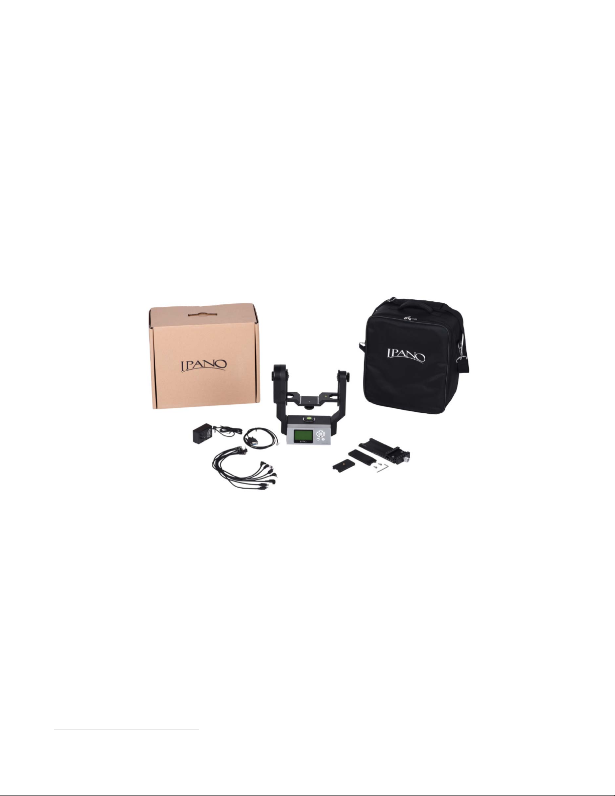
2.1. Parts List1
The iPano mount includes:
iPano AllView Pro mount
8.4V 2A battery charger
RS232 serial cable (RS232-RJ9)
Electronic trigger cables X7 (Canon N3, Canon E3, Nikon 10-pin, Nikon MC-DC1, Nikon
MC-DC2, Olympus RU-UC1, SONY RM-S1AM)
Vertical mounting dovetail plate
Vertical mounting dovetail plate screws X2
1/4" to 3/8" Camera Convert Screw Adapter
Hex key wrench
Padded carrying bag
Panoweaver 9.1 Standard Edition by Easypano (download from Easypano website)
One year limited warranty (90 day for Li-ion battery)
Figure 1. Package contents
ONLINE RESOURCES (check at www.iOptron.com)
Quick Start Guide
This instruction manual
Mount firmware upgrades (check online for latest version)
iPano
Reviews and feedback from other customers
Accessories
1
US market only. Actual contents may vary.
TM
Commander
6
Page 7
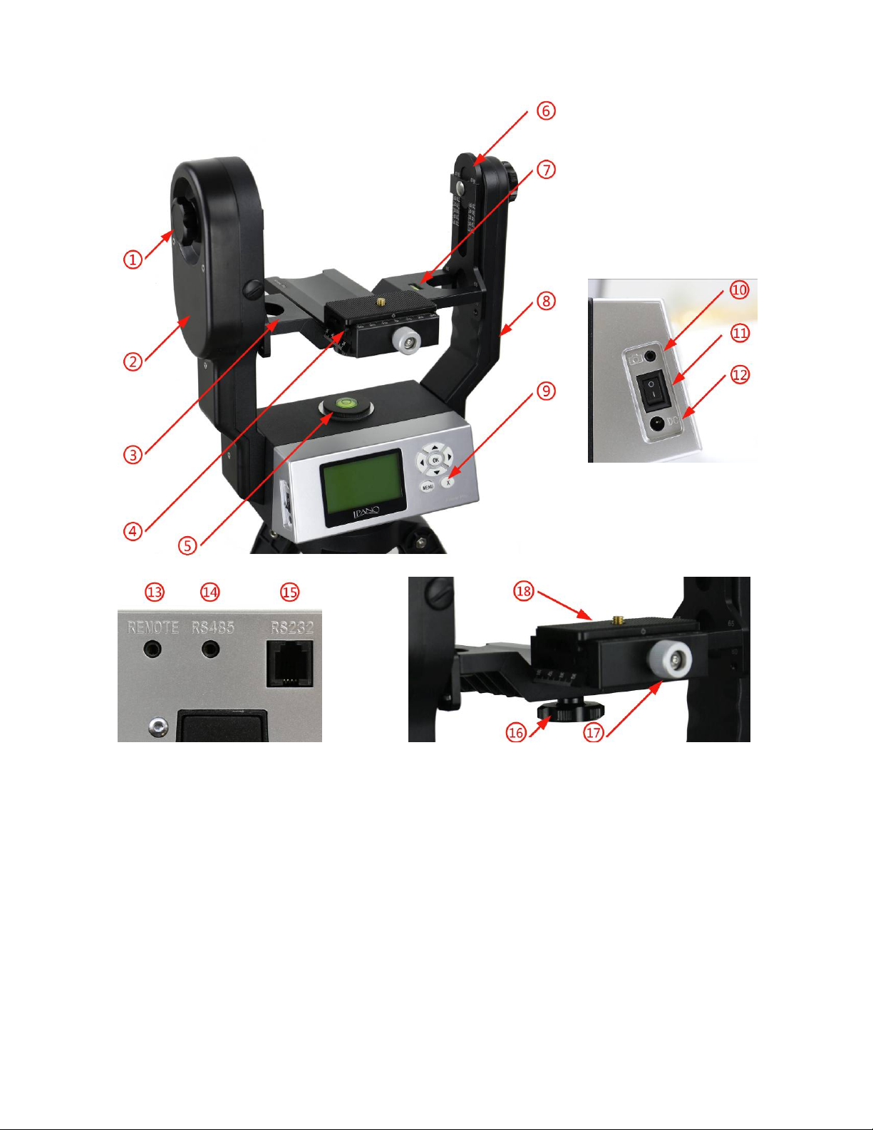
2.2. Identification of Parts
Figure 2. iPano mount assembly
1. Height Lock
2. Primary Arm
3. Camera Mounting Platform
4. Dovetail Mounting Module
5. Chassis Bubble Level
6. Height Scale
7. Camera Level Indicator
8. Auxiliary Arm
9. Key Pad
10. Trigger Cable Port
11. Power Switch
12. DC Input (7.4V to 8.4V)
13. REMOTE Trigger Port
14. RS485 Port
15. RS232 Serial Port
16. Dovetail Saddle Locking Knob
17. Quick Release Plate Locking Knob
18. Camera Quick Release Plate
7
Page 8
2.3. iPano Mount Assembly
2.3.1. Charge the battery
The iPano AllView Pro Mount uses a lithium rechargeable battery to power the mount. Please using the
included wall plug charger (8.4V/2A) to full charge the battery after receiving the mount. The LED
indicator remains RED during the charging process and will turn to GREEN when charge is complete.
DO NOT charge the mount with a 12V AC adapter/battery pack or a car cigarette plug. ONLY
charge the mount using the included battery charger! Charge the mount battery before every
operation.
NEVER charge the battery when it is below 0°C (32°F)
A low battery waning (a flashing battery status indicator or beeps) will occur if the battery is low. You
may keep using the mount by plug in a wall plug charger or a 7.4V-8.4V DC power source through DC
port #12. NEVER use this way when it is below 0°C (of 32°F).
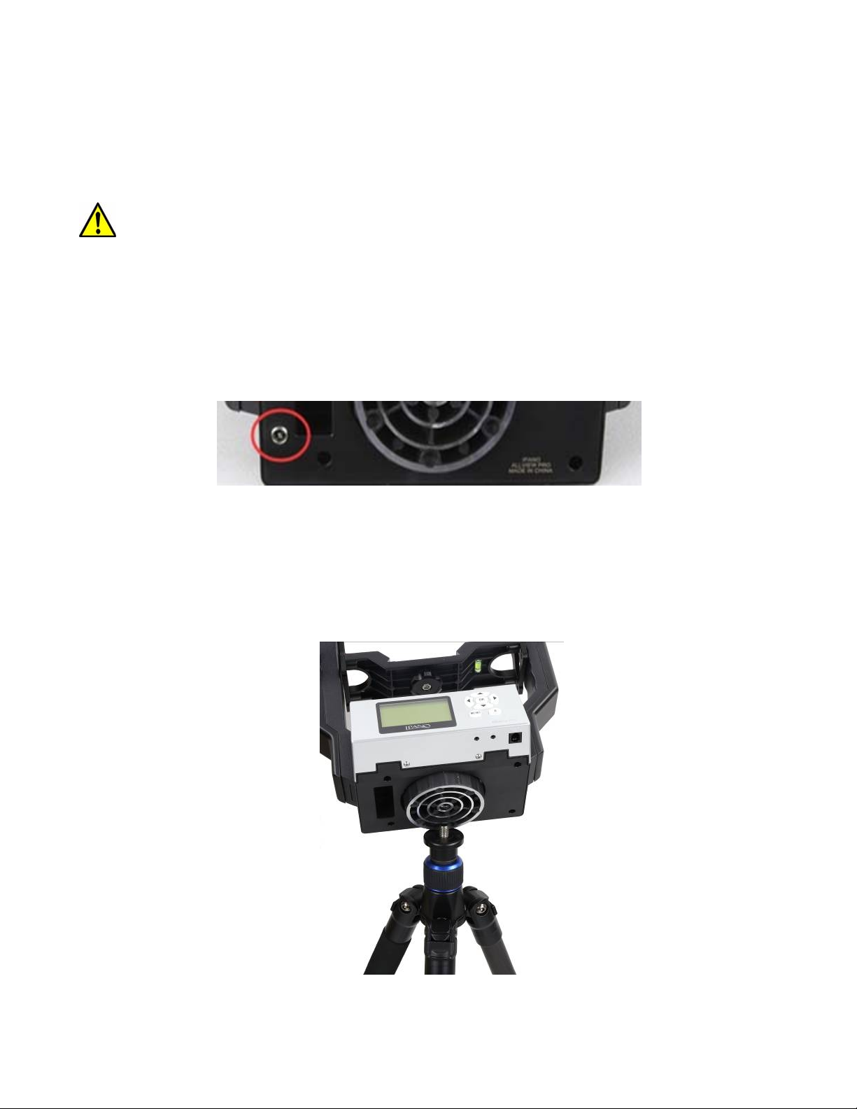
If you mount equipped a Direct DC Power Socket (DC 5.5mmX2.1mm) located at the bottom of the
mount (Figure 3), you can use a 7.4V portable power pack to keep operating the mount. Turn off the
mount before switch to portable power pack.
Figure 3. Direct Power Socket for 7.4V portable power pack
2.3.2. Attach the Mount
Carefully thread the iPano mount onto your tripod and make sure it is securely tightened. The mount
base has a 3/8” threaded socket. If your tripod only has a 1/4” threaded post, a 1/4” to 3/8” tripod
adapter screw (included) is needed,
Figure 4. Install the mount onto a tripod
8
Page 9
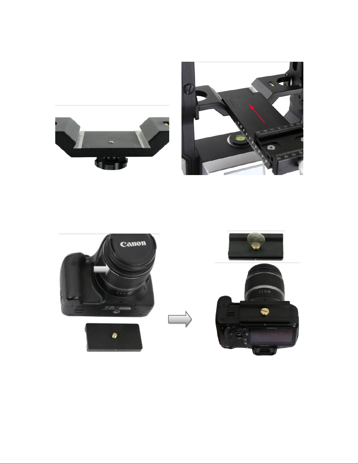
2.3.3. Install the Dovetail Mounting Module
Release the Dovetail Saddle Locking Knob #16 under the Camera Mounting Platform #3. Retreat the
tip of the Locking Knob #16 below the surface of the Platform. Slide the Dovetail Mounting Module #4
into the Camera Mounting Platform #3. Tighten the Locking Knob.
Figure 5. Install dovetail mounting module
2.3.4.
Remove the Camera Quick Release Plate #18 from the Dovetail Mounting Module #4 by releasing the
Plate Locking Knob #17. Install the Quick Release Plate #18 onto the camera tripod mounting hole of
your camera and align the edges. Tighten the brass screw using a coin if needed, as shown in Figure 6.
Attach the Camera
Figure 6 Mount a Quick Release Plate onto a camera
Mount the camera onto the Dovetail Mounting Module #4 by inserting the Quick Release Plate #18 into
the dovetail saddle. If the center of the lens of the camera is aligned with the tripod mounting hole, just
align the zero mark on the Quick Release Plate to the one on the dovetail saddle (Figure 7).
9
Page 10
Zero marks on Quick
Release Plate and
Dovetail Saddle
Figure 7 Align the zero marks
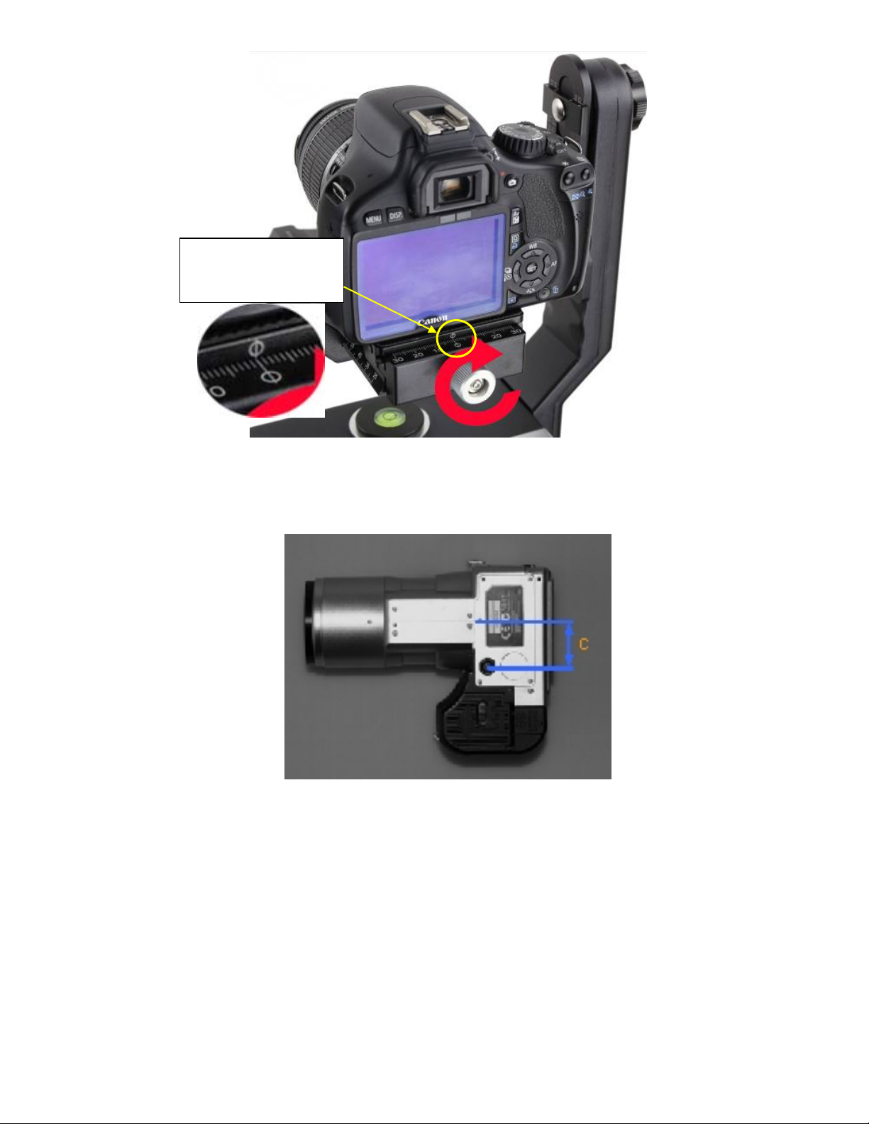
If the lens of a camera is off-centered from the tripod mounting hole by a distance C, as indicated in
Figure 8, you need to shift the zero mark on the Quick Release Plate by C to the zero mark on the
dovetail saddle.
Figure 8 A camera with an off-centered lens
Turn the Quick Release Plate Locking Knob #17 to lock the camera.
2.3.5. Level the Mount:
Adjust the tripod legs to level the mount by reading the Chassis Bubble Level Indicator #5 on the Mount
Base, as shown in Figure 9.
10
Page 11
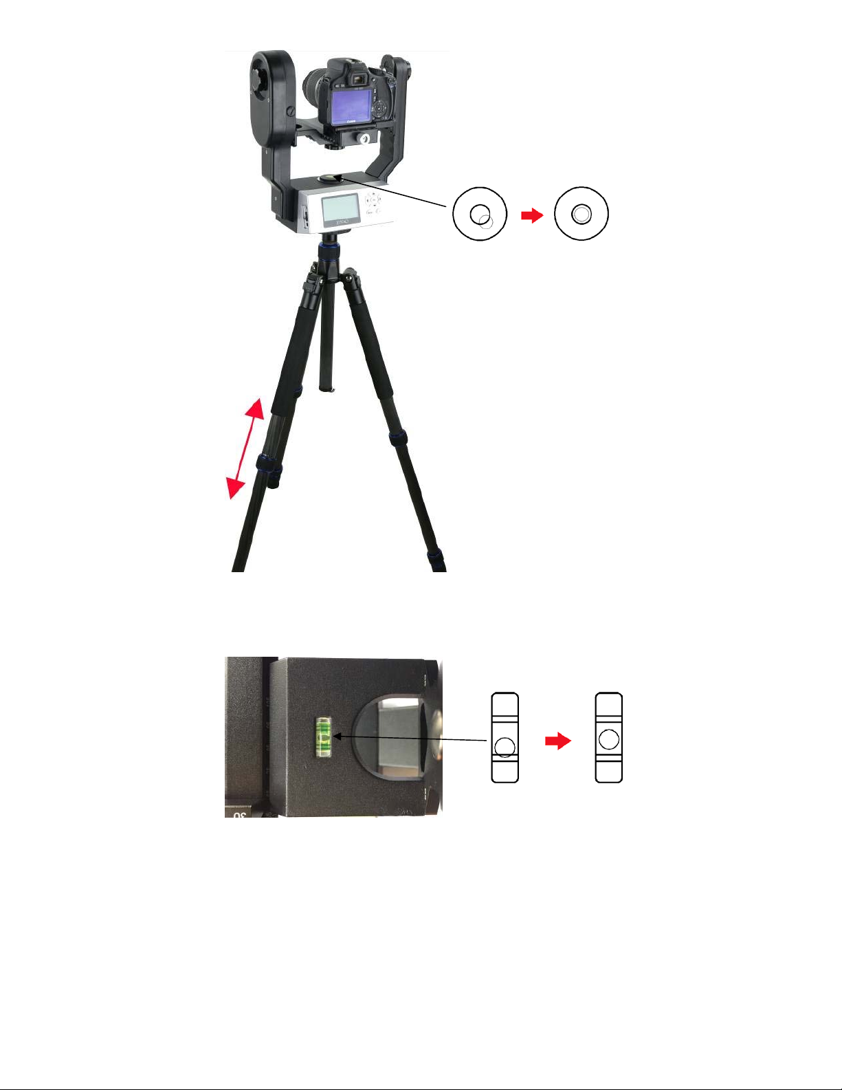
Figure 9 Level the mount
Use arrow button ▼ or ▲ to adjust the level of Camera Mounting Platform #3 by reading the Camera
Level Indicator #7, as shown in Figure 10. Use Shortcut Key to set the zero position (refer to 3.3.3).
Figure 10 Level the camera on the mount
2.3.6. Adjust the Camera
When taking photographs for a stitched panorama, the entrance pupil of the camera lens needs to be
kept in a constant position when the camera is rotated to point in a different direction for each shot.
This point is sometimes referred to as the No-Parallax Point (NPP), or Nodal point, or Entrance
Pupil, which can be accomplished by adjusting the Camera Mounting Platform #3 back and forth, and
Height Scale #6 up and down, as shown in Figure 11.
11
Page 12
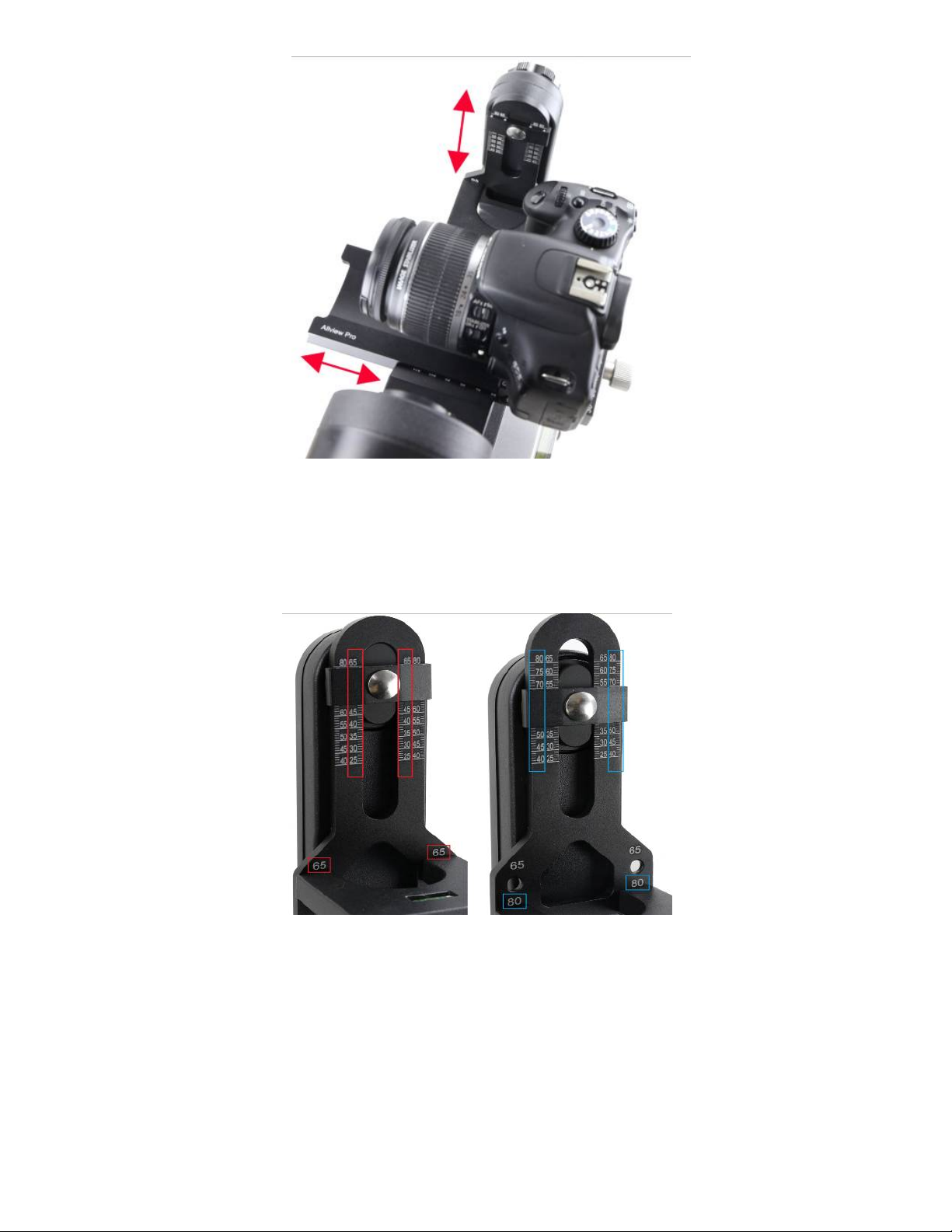
Figure 11 Adjust camera No-Parallax Point
There are two positions for Camera Mounting Platform #3: 65mm and 80mm, as shown in Figure 12. If
the distance from the base of the camera to the center of the lens is smaller than 65mm (see Figure
13), use the default setting on the Height Scale #6 (the inner scales). Otherwise, if the distance is
greater than 65mm, you need to lower the Camera Mounting Platform #3 to the 80mm position on the
Height Scale #6 and use the outer scales.
Figure 12 Maximum camera mount height 65mm and 80mm
Adjust Camera Height Position
Find the height number of the camera, the distance from the base of the camera to the center of the
lens. For example, the height number of a Canon EOS 5D Mark II is 43.5mm. Release Height Locks #1
on both Primary Arm #2 and Auxiliary Arm #8. Adjust the camera by moving the Camera Mounting
Platform #3 up and down so that the Height Scale #6 is set at the 43.5mm by reading the inner scale.
12
Page 13
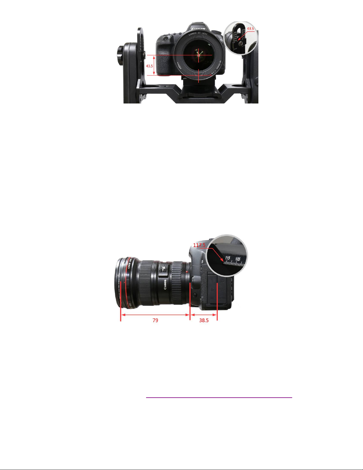
Figure 13 Adjust camera height position
Adjust Camera No-Parallax Point
Where is the No-Parallax Point? The physical location of the optical center is unique for each lens. For
prime lenses, the No-Parallax Point (with focus at infinity) is stationary. For zoom lenses, however, the
No-Parallax Point typically shifts for each focal length. The location of the No-Parallax Point is
commonly expressed as its distance, in millimeters.
Adjust the camera position based on the total entrance pupil distance. This number is the sum of the
camera length number, (the distance between the middle of the tripod mounting hole to the base of
the lens base, or base for adapter tube,) and the entrance pupil distance of the lens.
For example, the length number of a Canon EOS 5D Mark II is 38.5mm. The entrance pupil distance of
a Canon EF 16-35 F2.8 lens is 79mm at 16mm focal length. Therefore, the total entrance pupil distance
(or NPP) is:
38.5mm +79mm=117.5mm.
Figure 14 Adjust camera entrance pupil position
Slightly loosen the Dovetail Saddle Locking Knob #16. Move the Dovetail Mounting Module #4 back
and forth so that the 117.5mm mark on the dovetail bar is aligned to the edge of the Camera Mounting
Platform #3 (refer to the inlet in Figure 14). Tighten the Dovetail Saddle Locking Screw #16.
Note: Zoom lens has different entrance pupil distance at different focal length.
You can find camera mounting hole off-center, camera height, camera length and lens entrance pupil
position parameter from panotools.org (http://wiki.panotools.org/Entrance_Pupil_Database
A More Practical Way to Find the NPP
The NPP can be determined by experimentation. Here I show to do it:
13
).
Page 14

Find two vertical objects; one near, one far. Position your equipment so that these objects line
up in the viewfinder;
Level the iPano and camera;
Set the focal length of your camera;
Start out by positioning the approximate center of your lens over the axis of rotation;
Now pan the mount left;
If the rear object appears to shift to the left, then you are ahead of the No-Parallax Point. Slide
the Dovetail Mounting Module #4 forward and try again;
If the rear object appears to shift to the right, you are behind the No-Parallax Point. Slide the
Dovetail Mounting Module #4 back and try again;
When the optical center of the lens is directly over the axis of rotation, the rear object will not
appear to move relative to the front object;
Continue until objects stay aligned when you pan left and right;
Record your results so that your setup can be re-created.
14
Page 15

3. iPano Mount Operation
3.1. Key Pads Description
The following shows the keypads and its description.
▲ Camera tilt up
▼ Camera tilt down
◄ Mount pan left
► Mount pan right
OK Confirm
MENU Menu
X Return
3.2. LCD Display Panel and Icons
The following shows a LCD display main screen (left), with the description of each icon. The right image
displays more icons and their descriptions.
3.3. First Time Use and Shortcut Key
3.3.1. First Time Use
If it is the first time operating the mount, the AllView Pro mount will ask you to set up the iPano camera.
The system will ask:
Enter setup now? Press OK. If you press NO to skip, you’ll be asked to set it up later;
It will display current FOV (field of view) of your camera, which is 0.0 degree. Press OK to
continue.
Set camera’s zoom, then press OK;
Align horizon with top of camera screen: use ▼ key to tilt the camera downward until the top
of view finder/display screen aligned with horizon, then press OK;
Align horizon with bottom of camera screen: use ▲ key to tilt the camera upward until the
bottom of view finder/display screen aligned with horizon, then press OK.
15
Page 16

Before taking a panorama
you must setup your iPano
camera.
Enter setup now?
[X]=No [OK]=Yes
Set camera’s Zoom
[X]=Cancel [OK]=Done
Current FOV
0.0 vert degrees
[X]=Cancel [OK]=Set
Align horizon with top of
camera screen
[X]=Cancel [OK]=Next
Align horizon with bottom
of camera screen
[X]=Cancel [OK]=Set
Current FOV
25.1 vert degrees
[X]=Cancel [OK]=Done
Now you’ve set the camera reference.
3.3.2.
Test Electronic Shutter
Select an electronic trigger cable that is for your camera. Plug one end to your camera and the other
end into mount Trigger Cable Port #10 on the side of the mount. Turn both mount and camera on.
Press OK button to test the shutter. You should hear camera shutter operation.
The iPano mount comes with 7 trigger cables. If the one for your camera is not included, please contact
iOptron for additional cable or cable information.
3.3.3.
Shortcut Key
Press and hold MENU button to bring up the Shortcut Key menu. After level the camera, return the
Camera Mounting Platform back to level position, you may select Set Zero Position function to set the
current position as the Zero Position.
3.4. Quick Test Run
Set up the mount and camera;
Connect electronic trigger cable;
Turn on the mount;
Set FOV by following the on screen instruction, if this is the first time use the mount;
Press MENU button to bring up the operation menu; select Matrix Panorama and press OK;
Select one of 8 paths;
Follow the on screen instruction to select the starting point and the end point by using ◄, ►, ▲
or ▼ key and press OK;
Preview the Panorama. Press OK to show 4 corners and the center of a expected panorama;
The screen will display how many photos will be taken, press OK;
You need to confirm based on the mount and camera settings and make sure that:
o Camera on?
o Balance locked?
o Exposure locked (no auto exposure)?
16
Page 17

o Focus locked (no auto focus)?
o Flash off?
Select Start and press OK to start the test run using default setting parameters.
3.5. Turn Off the Mount
Remember to turn the mount power off at the end of the session. Charge the mount for next time use.
17
Page 18

4. Full Operation Menu
p
[X]
y
4.1. Matrix Panorama
The Matrix Panorama will provide a rectangular panorama photo. After setup the mount and camera,
phase the camera to the middle of the scene. Press MENU => Matrix Panorama. The system will
provide 8 moving paths to choose.
Move the cursor by press the arrow button and press OK to choose one. Follow the on screen
instruction to move the mount. For example, slew the camera to point to upper left corner using ◄
and▲ keys if we choose path 1. Press OK. Then move the camera to point lower right corner with
►and ► keys, press OK. The LCD will display the number of photos in each row and column the
camera will take, and the total time it needs, based on the camera and mount settings.
The mount will ask if you want to preview the panorama. Press X to skip the preview or OK to preview.
The mount will provide 5 positions for previewing: upper left corner, lower left corner, upper right corner,
lower right corner and center position. Press OK to start taking photos after previewing. If the Check
List is ON, the mount will ask a set of questions based on your parameter settings (see section 4.4)
before take the first photo to make sure that the camera is set correctly.
Here is an example to take a Matrix Panorama from upper left corner (340°,20°) to lower right corner
(20°,-20°)
Matrix Panorama
Circular Panorama
Time-lapse Photography
Custom Settings Bank
Global Settings
stem
S
320.00° 20.00°
Move camera to other
Diagonal position
[OK]=Continue
320.00° 20.00°
Upper left of pano
[OK]=Continue
320.00° 20.00°
Lower left of pano
[OK]=Continue
0.00° 0.00°
Move camera to any
Diagonal position
40.00° -20.00°
x5
x4 49s
=Cancel [OK]=Next
40.00° -20.00°
Upper right of pano
[OK]=Continue
0.00° 0.00°
Center position
[OK]=Continue
[OK]=Continue
Preview Panorama?
[X]=Ski
40.00° -20.00°
lower right of pano
[OK]=Continue
Start Panorama?
Take Pics:20
[X]=Back [OK]=Yes
[OK]=Yes
Camera on?
[OK]=Continue
Balance locked?
[OK]=Continue
18
Exposure locked?
[OK]=Continue
Page 19

p
[X]
y
Focus locked?
[OK]=Continue
Flash off?
[OK]=Continue
Using a 3x4 Matrix Panorama as an example. The mount will take the photo with the following path, if
the path 1 is chosen.
Figure 15. Panorama moving path 1
The mount is set to a default 3:2 Aspect Ratio and 30% Overlap.
4.2. Circular Panorama
The Circular Panorama will take 360 degree panoramas, both cylindrical panoramas and spherical
panoramas. Press MENU => Circular Panorama. Same as the Matrix Panorama, the mount will move
via one of eight (8) moving paths. After choosing a moving path, use the ▲ or ▼ button to set the
upper point (include zenith) and bottom point (as low as the camera w/lens can go). The mount will
calculate how many photos will be taken and if multiple paths are needed. The LCD will display the
number of photos in each row and column the camera will take, and the total time it needs, based on
the camera and mount settings.
The mount will ask if you want to preview the panorama. Press X to skip the preview or OK to preview.
The mount will provide 5 positions for previewing: upper left corner, lower left corner, upper right corner,
lower right corner and center position. Press OK to start taking photos. If the Check List is ON, the
mount will ask a set of question to make sure that the camera is set correctly.
Here is an example to take a Circular Panorama from 20° up to -20° down.
Matrix Panorama
Circular Panorama
Time-lapse Photography
Custom Settings Bank
Global Settings
stem
S
0.00° 0.00°
Move camera to start
position
[OK]=Continue
0.00° 20.00°
Move camera to other
position
[OK]=Continue
0.00° -20.00°
X14
x4 2m38s
=Cancel [OK]=Next
19
Preview Panorama?
[X]=Ski
[OK]=Yes
Page 20

4.3. Time-lapse Photography
y
This Time-lapse Photography allows you to create time-lapse images while the camera is moving. You
can pan, tilt or move diagonally the camera while taking the time-lapse images. You can set the delay
between each picture you are taking. To take a time-lapse panorama (panoramas over a period of time,)
please refer to Global Settings =>Interval Timer.
Press MENU => Time-laps Photography. First move the camera to the staring position using the
arrow key. Press OK to confirm. Then move the camera to the end position. Press OK. Now you can
choose either total picture numbers or angle intervals for the whole swing.
Here is an example to take a Time-lapse photography from upper left corner (320°,20°) to lower right
corner (40°,-20°)
Matrix Panorama
Circular Panorama
Time-lapse Photography
Custom Settings Bank
Global Settings
stem
S
40.00° -20.00°
Move camera to other
Diagonal position
[OK]=Continue
4.3.1.
Total Number
0.00° 0.00°
Move camera to start
position
[OK]=Continue
Select Total Number
Select Interval Degree
320.00° 20.00°
Move camera to end
position
[OK]=Continue
Enter the time delays (interval timer) between each picture. Use the ◄ and ► buttons to switch
between day, hour, minutes, and seconds. Use the ▲ and ▼ buttons to change the delay values where
cursor is blinking. Move the cursor down to Total number line using ► button. Set the total pictures
you want the camera to take with ▲ and ▼ buttons. Press OK to confirm. The mount will calculate the
angle intervals between each shot, and display total shots, interval timer and interval degrees. Press
OK to start.
Select Total Number
Select Interval Degree
Please input interval timer:
0 0 D 0 0 h 1 5 m 0 0 s
Total number:
[X]=Back [OK]=Continue
00010
10
00D00h15m00s
8.10
[X]=Back [OK]=Continue
4.3.2.
Interval Degree
Enter the time delays between each picture. Use the ◄ and ► buttons to switch between day, hour,
minutes, and seconds. Use the ▲ and ▼ buttons to change the delay values where cursor is blinking.
Move the cursor to Interval Degree line and set the angle that camera will move between each picture
taken. Press OK to confirm. The mount will calculate the total picture numbers. Press OK to start.
Select Total Number
Select Interval Degree
Please input interval timer:
0 0 D 0 0 h 1 5 m 0 0 s
Interval degree: 0 8 .1°
[X]=Back [OK]=Continue
20
10
00D00h15m00s
8.10
[X]=Back [OK]=Continue
Page 21

4.4. Customer Settings Bank
[B]
y
k
This function lets you store up to six (6) customized settings of parameters for a quick reload.
4.4.1.
Bank
The 6 banks, numbered from A to F, are available for storing customized parameters. These
parameters are AutoFocus (AF), Exposure, Mirror Lockup (Mup), Shutter Length, Repeat, Pretrigger
Delay and Camera Field of View (FOV).
Select a Bank
The cursor will be in the first line when enter this sub-menu. This is the bank currently in use. Press OK
button to enter next menu to choose a different bank. Use the ◄ and ► buttons to switch between
bank A to bank F, and press OK. Now you can either Load the stored parameters or Restoring
Default factory preset data (as shown in Bank B in following flow chart).
Matrix Panorama
Circular Panorama
Time-lapse Photography
Custom Settings Bank
Global Settings
stem
S
Bank A
Autofocus
Mirror Lock-up
Period/Exposure
Shutter Length
Shutter Feedbac
[A]
[1 ]
AF 0.10s 0.6s
Mup 0.50s 0.5s
1 0.1s
FOV 25.0°
[B]
[2 ]
AF 0.10s
Mup 0.50s
5
FOV 0.0°
0.5s
0.5s
0.1s
In bank B, the numbers with strikethrough indicates this function is OFF, such as AF 0.10s
Load
Restoring Default
means
Autofocus is OFF.
Customize a Bank Title
To enter description of a customer bank, press ▼ button to move the cursor to title line (second line).
Press OK button to bring up a soft keypad. Move the cursor and press OK to enter the
letter/number/sign on the cursor position. Press and HOLD the OK key to finish the entering.
To delete a character, press and hold MENU button while move the ◄ or ► key to the character to be
deleted. Release the MENU button and press the MENU button once to complete the deleting.
[B]
[2 ]
AF 0.10s
Mup 0.50s
5
FOV 0.0°
[Canon E ]
! ” # $ % ’ ( ) * + , - . /
0123456789:;<>?
@ABCDEFGHIJKLMNO
PQRSTUVWXYZ[\]^_
`abcdefghijklmno
pqrstuvwxyz{|}~.
0.5s
0.5s
0.1s
Load
Restoring Default
Save the changes?
[X]=Back [OK]=Yes
Load new parameters?
[X]=Back [OK]=Yes
21
Page 22

Press OK to save the changes.
gg
k
k
k
Here is the flow to record parameters to a specific bank, for example Bank D. Use MENU =>
Custom Settings Bank => select Bank A (or the bank is currently in use) => OK => use arrow key
to change it to [D] => OK => Load => OK to confirm.
Press X button to go back to Bank D menu. Go to settings below.
At the end of the setting, the parameter will be stored in the Bank D you selected and it will loaded
automatically next time the mount is turned on, until you change the settings or load a different bank.
4.4.2.
Autofocus
Turn the camera auto focus ON and OFF by moving the cursor and press OK button. Confirm saving
the changes. The factory default setting is Off.
Bank D
Autofocus
Mirror Lock-up
Period/Exposure
Shutter Length
Shutter Feedbac
4.4.3.
Time/Focus
Bank D
Autofocus
Mirror Lock-up
Period/Exposure
Shutter Length
Shutter Feedbac
AutoFocus Off
Off OK
On
When the Autofocus is turned ON, the Time/Focus submenu will be displayed. This function will set
how long the camera will take to do the auto focus. The factory default setting is 0.10 seconds. The
time can be set from 0.05 seconds to 1 second, with 0.05 seconds increments. Move the cursor to a
desired number, press OK to select and confirm.
Autofocus
Times/Focus
Mirror Lock-up
Period/Exposure
Shutter Length
Shutter Feedbac
Times/Focus 0.10s
0.05s
0.10s OK
0.15s
0.20s
4.4.4.
Mirror Lock-up
Turn the camera Mirror Lock-up function ON and OFF. The factory default setting is Off.
Times/Focus
Mirror Lock-up
Period/Exposure
Shutter Length
Shutter Feedback
Pretri
4.4.5.
er Delay
Lock-up Time
Mirror Lock-up Off
Off OK
On
When Mirror Lock-up is set to ON, the Lock-up Time submenu will be displayed. This will allow you
set how long the mirror will be flipped up and delayed before the shutter is triggered. The delay ranges
from 0.25 seconds to 3 seconds with 0.25 seconds increments. The factory default setting is 0.50
seconds.
22
Page 23

p
Mirror Lock-up
gg
Lock-up Time
Period/Exposure
Shutter Length
Shutter Feedback
Pretri
er Delay
Lock-up Time 0.50s
0.25s
0.50s OK
0.75s
1.00s
4.4.6.
Period/Exposure
Set the total time between the start of the shutter triggering and the next mount movement. It can be set
from 0.1s to 60s. The factory default setting is 0.5 seconds.
Lock-up Time
Period/Exposure
Shutter Length
Shutter Feedback
Pretrigger Delay
Camera Setu
4.4.7.
Shutter Length
Period/Exposure 0.5s
0.25s
0.50s OK
0.75s
1.00s
The amount of time that shutter signal is asserted ranging from bulb (B), 0.1 to 8 seconds. The factory
default setting is 0.5 seconds.
Period/Exposure
Shutter Length
Shutter Feedback
Pretrigger Delay
Camera Setup
Bank D
4.4.8.
Shutter Feedback
Shutter Length 0.5s
0.25s
0.50s OK
0.75s
1.00s
This function is used to automatically detect a missed shutter trigger, hence a missed photograph at
each position. The factory default setting is Off.
Shutter Length
Shutter Feedback
Pretrigger Delay
Camera Setup
Bank D
Autofocus
Shutter Feedback Off
Off OK
On
4.4.9. Shutter Retries
When the Shutter Feedback is turned ON, the Shutter Retries submenu will be displayed. This
function will allow you to set how many times the camera will try to trig the shutter until it takes a photo
successfully. It can be set to try from 1 to 10 times. The factory default setting is 5.
Shutter Feedback
Shutter Retries
Pretrigger Delay
Camera Setup
Bank D
Autofocus
Shutter Retries 5
5 OK
6
7
8
23
Page 24

y
k
T
4.4.10.
Pretrigger Delay
This delay is between the end of the mount movement and beginning of the trigger signal to your
camera. It will allow the camera to settle after mount movement. The delay time can be set at 0.0s, 0.1s,
0.2s, 0.3s, 0.4s, 0.5s, 0.6s, 0.7s, 0.8s, 0.9s, 1.0s, 1.5s, 2.0s, 2.5s or 3 seconds. The default is 0.1s.
Shutter Retries
Pretrigger Delay
Camera Setup
Bank D
Autofocus
ime/Focus
4.4.11.
Camera Setup
Pretrigger Delay 0.1s
0.0s
0.1s OK
0.2s
0.3s
This will work through you to set the camera FOV. If you have a zoom lens, you need to set the zoom
first. Follow the instruction on the screen to set up the camera FOV. Use ▼ key to tilt the camera
downward until the top of view finder/display screen aligned with horizon, then press OK. Use ▲ key to
tilt the camera upward until the bottom of view finder/display screen aligned with horizon, then press
OK.
Pretrigger Delay
Camera Setup
Bank D
Autofocus
Time/Focus
Mirror Loc
-up
Current FOV
0.0 vert degrees
[X]=Cancel [OK]=Set
Set camera’s Zoom
[X]=Cancel [OK]=Done
Align horizon with top of
camera screen
[X]=Cancel [OK]=Next
Align horizon with top of
camera screen
[X]=Cancel [OK]=Next
Current FOV
20.0 vert degrees
[X]=Cancel [OK]=Set
4.5. Global Settings
4.5.1. Aspect Ratio
Set the ratio of the width to height of the camera system. The default setting is 3:2. You may set the
aspect ratio to 1:1, 3:2, 4:3 and 16:9, as well as customer values from 0.50:1 to 2:00:1.
Matrix Panorama
Circular Panorama
Time-lapse Photography
Custom Settings Bank
Global Settings
stem
S
4.5.2.
Picture Overlap
Aspect Ratio
Picture Overlap
Rotate Tall
Multi Picture
Interval Timer
Brackets
Aspect Ratio 3:2
1:1
3:2 OK
4:3
16:9
Set the overlap between each photos for panorama stitch. The overlap can be selected from 25% to
75%, with 5% increments. The default setting is 30%.
24
Page 25

g
y
Aspect Ratio
Picture Overlap
Rotate Tall
Multi Picture
Interval Timer
Brackets
Picture Overlap 30%
25%
30% OK
35%
40%
4.5.3.
Rotate Tall
Choose take the photo in landscape (normal) or portrait orientation. The default setting is Disable
(landscape). If you enable this function, make sure that the camera is mounted in vertical with the
vertical mounting dovetail plate.
Picture Overlap
Rotate Tall
Multi Picture
Interval Timer
Brackets
Bracket Dela
4.5.4.
Multi Picture
Rotate Tall Disable
Disable OK
Enable
This function will let you set the number of photographs that will be triggered per position, up to 20. The
default is 1.
Rotate Tall
Multi Picture
Interval Timer
Brackets
Bracket Delay
Start Del/tri
Multi Picture 1
1 OK
2
3
4
4.5.5.
Interval Timer
This will set the mount to take a series of panoramas over a period of time. If Disable is selected, the
mount will stop at the end of a session. If Ext. Trigger is selected, the mount will wait for the remote
signal to start the panorama again. If Timer is selected, you can enter how long the mount will wait until
next session is started, until you stop the mount.
Multi Picture
Interval Timer
Brackets
Bracket Delay
Start Del/trig
Check List
Save the changes?
[X]=Back [OK]=Yes
Interval Timer Disable
Disable OK
Ext. trigger
Timer
0D
0
00:00:00
Interval Timer Disable
Disable
Ext. trigger
Timer OK
This function will take panorama time-lapse photos.
25
Page 26

4.5.6. Brackets
p
p
Set exposure bracketing of 1, 3, 5, 7, or 9 photographs for HDR images by working with the camera
AEB (automatic exposure bracketing) firmware. If the Bracket setting is more than 1, use the EV Step
Size setting to set the separation of exposure values. The default bracket is 1.
Interval Timer
Brackets
Bracket Delay
Start Del/trig
Check List
Shutter Mode
4.5.7.
EV Step Size
Brackets 1
1 OK
3
5
7
Set the separation of exposure values (EVs) to 0.3, 0.7, 1.0, 1.3, 1.7 or 2.0.
Brackets
EV Step Size
Bracket Delay
Start Del/trig
Check List
Shutter Mode
4.5.8.
Bracket Delay
Bracket Delay 0.3
0.3 OK
0.7
1.0
1.3
Set time delay between Brackets to allow your camera enough time to transfer the images. The delay
can be set between 0.1 and 8 seconds.
EV Step Size
Bracket Delay
Start Del/trig
Check List
Shutter Mode
ect Ratio
As
Bracket Delay 0.1s
0.1s OK
0.2s
0.3s
0.4s
4.5.9.
Start Del/Trig
This function tells mount when to start take the photo:
None: immediate after mount set up is done;
Ext. trigger: start when an external trigger signal is received;
15s ~ 5m: start the mount after 15s, 30s, 45s, 1m, 2m or 5 minutes delay;
Timer: star at a preset time (up to 24 hours).
The default setting is None (no delay). To use the Timer:
Bracket Delay
Start Del/trig
Check List
Shutter Mode
Aspect Ratio
Picture Overla
Start Del/trig None
None OK
Ext. trigger
15s
30s
26
Start Del/trig None
Timer OK
Page 27

p
Save the changes?
[X]=Back [OK]=Yes
0:00:00
0
4.5.10.
Check List
If Check List is selected, the mount will prompt you to check the camera based on your settings or
which Custom Settings Bank is choosing before panorama capture begins. The default is On.
Start Del/trig
Check List
Shutter Mode
Aspect Ratio
Picture Overlap
Rotate Tall
4.5.11.
Shutter Mode
Check List On
Off
On OK
This function allows you to choose how the mount will operate the camera’s shutter. If Remote is
selected, the mount will trigger the shutter via the electronic trigger cable connected to the remote
shutter port on the camera. If Manual is chosen, you’ll need to manually actuate the camera shutter and
press the OK button on the mount to advance to the next photograph. The default is Auto.
Check List
Shutter Mode
Aspect Ratio
Picture Overlap
Rotate Tall
Multi Picture
Shutter Mode Auto
Auto OK
Manual
4.6. System
4.6.1. Language
Select system language. Currently it has English and Chinese (中文).
Matrix Panorama
Circular Panorama
Time-lapse Photography
Custom Settings Bank
Global Settings
System
Language
Firmware Information
Factory Reset
Wi-Fi Switch
Wi-Fi Options
Set Bee
4.7. Firmware Information
Display system firmware version.
27
English
中文
Page 28

y
guag
Language
p
Firmware Information
Factory Reset
Wi-Fi Switch
Wi-Fi Options
Set Bee
iPano+ V1.00
Main_Ver:150629
WiFi_Ver:V1.0.07
WiFi_Drv:141440,V9
4.7.1.
Factory Reset
Reset the system to factory default value and all the data will be lost.
4.7.2.
Wi-Fi Switch
Turn ON/OFF built-in Wi-Fi module. When the Wi-Fi is turned on (default setting), the iPano mount will
broadcast itself with a Wi-Fi SSID iPano_XXXXXX (can be customized). It can be discovered by and
connected to a Computer/Tablet/SmartPhone and be controlled wirelessly with a proper software/App.
Factory Reset
Wi-Fi Switch
Wi-Fi Options
Set Beep
LCD Contrast
Lan
4.7.3.
e
Wi-Fi Option
Wi-Fi Switch On
Off
On OK
This option will display current Wi-Fi module information and restart/reset the WI-Fi adapter.
Information: display the basic information of the Wi-Fi module. It can be changed through a
computer via RS232 port.
Reset Wi-Fi: restart the Wi-Fi module.
Factory WI-Fi: reset all the Wi-Fi information and settings to factory default. Customized SSID
or password will be lost.
Wi-Fi Switch
Wi-Fi Options
Set Beep
LCD Contrast
Language
Firmware Information
4.7.4.
Set Beep
Information
Reset Wi-Fi
Factory Wi-Fi
Set when the mount will beep.
Wi-Fi Options
Set Beep
LCD Contrast
Language
Firmware Information
Factor
4.7.5.
Reset
LCD Contrast
Always On
On but Keyboard
Always Off
Adjust LCD display contrast using ◄ or ► button.
SSID: iPano_442DEC
Network mode: 11BGN
Select channel: CH1
Password: None
28
Page 29

4.8. Camera Parameter
For storing your camera and lens’ basic parameters, such as Center Position, Camera Height, Entry
Pupil Positions for the camera and lens.
4.9. Short Cut Key
Hold the MENU button will bring up the Short cut Key menu.
Last Project
Camera Setup
Goto Zero Position
Set Zero Position
4.9.1.
Select this one if you want to repeat the last panorama project.
4.9.2.
Set up the camera zoom and FOV for the current project while keep other settings the same.
4.9.3.
Send the mount back to zero position, the initial pointing direction.
4.9.4.
Set the current position as mount’s zero position. Use this function after you set up and level the mount
to reset the mount initial pointing coordinate to (0,0).
Latest Project
Camera Setup
Goto Zero Position
Set Zero Position
29
Page 30

5. iPano AllView Mount Remote Control
A PC computer may be used to setup and control an iPano AllView Pro mount via iPano Commander.
The iPano mount can be connected to a PC via a serial cable or wirelessly.
An iPano mount can also be controlled by an iOS version iPano Commander.
5.1. Connect the mount to a computer via a serial cable
If the computer has a 9-pin, D-shape male serial port (i.e, COM port or RS232 port), connect the
supplied serial cable between the computer RS232 port and the mount RS232 port.
Figure 16. Native serial (RS232) port
If the computer only has USB ports, like most laptops do, a USB to COM converter is needed to convert
one USB port to a COM port. Here are two examples of USB2COM converters. iOptron suggests you to
acquire one with FTDI chipset.
Figure 17. USB-RS232 converters
Follow the instruction comes with the converter to install the driver. Plug the converter into one of the
available USB port of the computer. Then connect the serial cable between the RS232 ports of the
converter and the mount (Figure 18).
Figure 18. Connect RJ-9 cable to mount
Download and install iPano Commander. When a Communication Port Settings screen is opened on
your computer screen, select RS232/USB Port, click OK to connect the mount to the computer.
Figure 19. iPano Commander Port Settings
30
Page 31

5.2. Connect the mount to a computer via a Wi-Fi connection
The iPano mount has a built-in Wi-Fi connection. Open the Wi-Fi connection panel on your computer.
Find a Wi-Fi SSID called “iPano_XXXXXX”, as shown below and connect it.
Figure 20. Wi-Fi connection
5.3. iPano Commander
After the mount is connected, iPano Commander will be loaded. Now you can set the parameter on
your computer. Some parameter changes need select Change Setting button first before any change
can be made.
Figure 21. iPano Commander Interface
5.4. Connect a iPad/iPhone to a iPano mount Wi-Fi Connection
Download iPano Commader App from iTune store first
(https://itunes.apple.com/us/app/ipano-commander/id1058694402?mt=8
31
).
Page 32

Connect the iPad/iPhone to the iPano_XXXXXX wireless network. Tap iPano Commander on
your iPad/iPhone.
Now you make your iPad/iPhone a iPano remote controller. Watch the demo on YouTube
iOS iPano Commander Demo
Figure 22. iPad/iPhone Wi-Fi connection
32
Page 33

Figure 23. iOS iPano Commander interface
33
Page 34

6. Image Processing
The processing software, Panoweaver 9 Standard Edition by Easypano is included. It can be download
from Easypano website (http://www.easypano.com/download-panorama-software.html
to the software website for more detailed information, including Video Tutorial and Online User Manual.
You may also use other stitching programs you are already familiar with, such as PTGui and Autopano.
There are also free options from Hugin and Microsoft ICE.
Then you can share or publish your panoramas online. If you’re adding 360 panos to your website or
blog, Pano2VR, krpano, and PanoTour are interactive panorama viewers that offer lots of options. Or a
simpler way to get your 360 panoramas online is to use 360Cities or Google Maps.
). You may refer
34
Page 35

7. Wi-Fi Configuration
p
The iPano Wi-Fi is shipped with no password protection. You can change the SSID and enable
password protection so only you can make the connection.
To change the Wi-Fi settings:
Connect the computer/tablet/SmartPhone to iPano Wi-Fi;
Open the internet browser and type in http://10.10.100.254
A login window will open. Enter “admin” as both User Name and Password;
Go to AP Settings;
Now you can change the SSID name from iPano_XXXXXX to Your Name, enable WPA2
encryption, etc.;
You may also go to account to change login name and password;
Restart the mount.
Note:
1. Please keep the Wi-Fi at AP (access point) mode
2. If ever you forgot your password, use “Factory Wi-Fi” to reset the WI-FI to factory default
settings.
;
Matrix Panorama
Circular Panorama
Time-lapse Photography
Custom Settings Bank
Global Settings
System
Language
Firmware Information
Factory Reset
Wi-Fi Switch
Wi-Fi Options
Set Bee
Information
Reset Wi-Fi
Factory Wi-Fi
35
Page 36

8. Maintenance and Servicing
8.1. Maintenance
The iPano AllView Pro mount is designed to be maintenance free. Do not overload the mount. Do not
drop the mount as this will damage the mount and / or permanently degrade performance. Use a wet
cloth to clean the mount and hand controller. Do not use solvent.
Charge the battery regularly if the mount is not in use for a period of time. Replacement battery is
available.
8.2. iOptron Customer Service
If you have any question concerning your mount contact iOptron Customer Service Department.
Customer Service hours are 9:00 AM to 5:00 PM, Eastern Time, Monday through Friday. In the unlikely
event that the mount requires factory servicing or repairing, write or call iOptron Customer Service
Department first to receive an Return Merchandise Authorization Number (RMA#) before returning the
mount to the factory. Please provide details as to the nature of the problem as well as your name,
address, e-mail address, purchase information and daytime telephone number. We have found that
most problems can be resolved by e-mails or telephone calls. So please contact iOptron first to avoid
returning the mount for repair.
It is strongly suggested that to send technical questions to support@ioptron.com
1.781.569.0200.
8.3. Product End of Life Disposal Instructions
This electronic product is subject to disposal and recycling regulations that vary by
country and region. It is your responsibility to recycle your electronic equipment per your
local environmental laws and regulations to ensure that it will be recycled in a manner
that protects human health and the environment. To find out where you can drop off your
waste equipment for recycling, please contact your local waste recycle/disposal service
or the product representative.
8.4. Battery Replacement and Disposal Instructions
Battery Disposal: Batteries contain chemicals that, if released, may affect the
environment and human health. Batteries should be collected separately for recycling,
and recycled at a local hazardous material disposal location adhering to your country and
local government regulations. To find out where you can drop off your waste battery for
recycling, please contact your local waste disposal service or the product representative.
. Call in the U.S.
36
Page 37

Appendix A. Technical Specifications
Mount iPano AllVtew Pro Camera Mount
Operation Mode Panorama/Turntable
Mount Structure U-shaped, double-arm, all enclosed
Frame material Aluminum alloy
Payload
Weight 3.3kg (7.3 lbs, including battery)
Size 20.3 X 28 X 13.3 cm (12 X 11 X 5.25 in.)
Fitted Camera
Camera Mounting Horizontal/vertical
Motor Stepper motors
Drive Train Metal worm/gear with synchronize belt
Motion Concurrent biaxial, no backlash, no play, no vibration
Motion Range Pan: 360°, Tilt: +90° to -90° (camera lens may block)
Motion Increment 0.0001° per step
Pan-tilt Precision 0.01°
Maximum slew speed Pan: 15°/sec, Tilt: 8°/sec
Battery Built-in rechargeable Li-ion battery (7.4V, 4.4AH, 32.6WH)
Operation time Continuous 50,000 shots (at 1 shot/sec rate)
Battery charger 100-240V AC input /8.4V DC 2000mA output (Included)
Control Display 128 X 64 pixel LCD
Electronic Trigger Cables
Remote Trigger Interface 2.5mm three-contact TRS socket (earphone jacket)
Wireless Communication Full Wi-Fi control via iPano Commander
I/O Port
Firmware upgrade User upgradable
Padded Carrying Bag Included
Operation temperature -10ºC ~ 40ºC
Warranty
Lens center to camera bottom < 80 mm (3.15 in.) – most
Canon N3; Canon E3; Nikon 10 Pin; Nikon MC–DC1; Nikon
MC–DC2; Olympus RM-UC1 and Sony RM-S1AM
Full control via RS232 command set or iPano Commander
Panorama – 5kg (11 lbs)
Turntable – 10kg (22 lbs)
(RS485 for future application)
Mount: one year limited
Battery: 90 day limited
DSLR
37
Page 38

Appendix B. iPanoTM AllView ProTM Camera Mount MENU
MENU
Matrix Panorama
Circular Panorama
Time-lapse Pho tog rapy
Custom Settings Bank
Bank
Autofocus
Time/ Fo cus
Mirror Lo ck-up
Lock-up Time
Period/Exposure
Shutter Length
Shutter Feedback
Shutter Retries
Pretrigger Delay
Camera Setup
Global Settings
Aspect Ratio
Picture Overlap
Rotate Tall
Multi Picture
Interval Timer
Brackets
EV Step Size
Bracket Delay
Start Del/trig
Check List
Shutter Mode
38
Page 39

System
Language
Firmware Inf o rmatio n
Factory Reset
Wi-Fi Switc h
Wi-Fi Optio n
Set Beep
LCD Contrast
Camera Parameter
39
Page 40

Appendix C. Firmware Upgrade
The firmware in iPano AllView Pro can be upgraded by the customer. Please check iOptron’s
website, http://www.iOptron.com, under Support > Firmware/Software for details.
40
Page 41

Appendix D. Supported Camera
There are 7 camera shutter tripper cables are included in an iPano mount. An optional Sony S2 cable
(#3610-08) is also available on www.ioptron.com
.
Canon E3 trigger cable
(#3610-01)
Canon N3 trigger cable
(#3610-02)
Canon:
60D, 70D, All 'Rebels' (100D, 300D, 350D, 400D, 450D, 500D,
550D, 600D, 650D, 700D, 1000D, 1100D, etc), T5i, T4i, T3i, T3,
T2i,T1i, TXi, XTi, SL1, Kiss, SX50, G10, G11, G12, G15, G16, G1X
Pentax:
K3, K5, K7, K30, K50, K500, K100D, K110D, K10D, K200, K20D, K5
II, K5 IIs, *ist D, *ist DL, *ist Ds, *ist DS2, *ist DL2,
Samsung:
GX-1L, GX-1S, GX-10, GX-20, NX5, NX10, NX100.
Canon:
EOS: 1D series, 5D series, 7D, 50D, 40D. 30D, 20D, 10D.
(Compatible with the device under shutter release mode)
Nikon DC-MC1 trigger cable
(#3610-03)
Nikon:
DSLR D80 and D70
41
Page 42

Nikon DC-MC2 trigger cable
Nikon:
(#3610-04)
Nikon 10-pin trigger cable
(#3610-05)
D90, D3100, D3200, D3300, D5000, D5100, D5200, D5300, D5500,
D7000, D7100, D7200, D600, D610, D750
Nikon:
D1, D1H, D1X, D2, D200, D2H, D2Hs, D2X, D2Xs, D3, D300,
D300s, D3s, D3x, D4, D4s, D700, D800, D800e and D810
Fuji:
S3 and S5
Olympus RM-UC1 trigger cable
(#3610-06)
Kodak:
DCS-14N
Olympus:
Olympus SP-510UZ, SP-550UZ, SP-560UZ, SP-5655Z, SP-570UZ,
SP-590 UZ and SZ-30MR, SZ-31MR his, XZ-1, XZ-10, SP-100EE,
OM-D E-M5, OM-D E-M5 Mark II Digital Camera
Olympus PEN E-P1, E-P2, E-P5, E-PL2, E-PL3, E-PL5, E-PL6, EPL7, E-PM1, E-PM2 Digital Camera
Olympus Evolt E410, E-420, E-450, E-510, E-520, E-600, E-620, E30 Digital SLR Camera
42
Page 43

Sony RM-S1AM trigger cable
Sony:
(#3610-07)
Optional
Sony S2 trigger cable
(#3610-08)
Alpha DSLR-A100 A200 A300 A350 A450 A500 A550 A560 A580,
A700 A900
Alpha SLT-A77, SLT-A65, SLT-A55, SLT-A35, SLT-A33,
Minolta:
Maxxum/Dynax/AF 7D, 5D, 9, 7, 5, 4, 3, 807si, 800si, 700si, 600si,
505si, 500si, 9000, 7000, 5000
DiMAGE 7Hi, 7i, 7, 5, A1, A2, A200
Sony:
Alpha A7 / A7R / A7S / A3000 / A5000 / A6000
SLT-A58
NEX-3NL
DSC-HX300 / HX50V, DSC-RX100II, DSC-RX100III
43
Page 44

IOPTRON WARRANTY
1. iOptron battery has 90 day limited warranty
2. iPanoTM AllView ProTM mount has one year limited warranty
A. iOptron warrants your iPanoTM AllView ProTM camera mount to be free from defects in materials and workmanship for one year from
date of the purchase. iOptron will repair or replace such product or part which, upon inspection by iOptron, is found to be defective in
materials or workmanship. As a condition to the obligation of iOptron to repair or replace such product, the product must be returned to
iOptron together with a proof-of-purchase satisfactory to iOptron.
B. A proper Return Merchant Authorization Number must be obtained from iOptron in advance of return. Call iOptron at 1.781.569.0200
or contact iOptron at support@ioptron.com via e-mail to receive the RMA number to be displayed on the outside of your shipping
container.
All returns must be accompanied by a written statement stating the name, address, and daytime telephone number of the owner,
together with a brief description of any claimed defects. Parts or product for which replacement is made shall become the property of
iOptron.
The customer shall be responsible for all costs of transportation and insurance, both to and from the factory of iOptron, and shall be
required to prepay such costs.
iOptron shall use reasonable efforts to repair or replace a mount covered by this warranty within thirty days of receipt. In the event repair
or replacement shall require more than thirty days, iOptron shall notify the customer accordingly. iOptron reserves the right to replace any
product which has been discontinued from its product line with a new product of comparable value and function.
This warranty shall be void and of no force of effect in the event a covered product has been modified in design or function, or subjected
to abuse, misuse, mishandling or unauthorized repair. Further, product malfunction or deterioration due to normal wear is not covered by
this warranty.
IOPTRON DISCLAIMS ANY WARRANTIES, EXPRESS OR IMPLIED, WHETHER OF MERCHANTABILITY OF FITNESS FOR A
PARTICULAR USE, EXCEPT AS EXPRESSLY SET FORTH HERE. THE SOLE OBLIGATION OF IOPTRON UNDER THIS LIMITED
WARRANTY SHALL BE TO REPAIR OR REPLACE THE COVERED PRODUCT, IN ACCORDANCE WITH THE TERMS SET FORTH
HERE. IOPTRON EXPRESSLY DISCLAIMS ANY LOST PROFITS, GENERAL, SPECIAL, INDIRECT OR CONSEQUENTIAL
DAMAGES WHICH MAY RESULT FROM BREACH OF ANY WARRANTY, OR ARISING OUT OF THE USE OR INABILITY TO USE
ANY IOPTRON PRODUCT. ANY WARRANTIES WHICH ARE IMPLIED AND WHICH CANNOT BE DISCLAIMED SHALL BE LIMITED
IN DURATION TO A TERM OF TWO YEARS FROM THE DATE OF ORIGINAL RETAIL PURCHASE.
Some states do not allow the exclusion or limitation of incidental or consequential damages or limitation on how long an implied warranty
lasts, so the above limitations and exclusions may not apply to you.
This warranty gives you specific legal rights, and you may also have other rights which vary from state to state.
iOptron reserves the right to modify or discontinue, without prior notice to you, any model or style mount.
If warranty problems arise, or if you need assistance in using your mount contact:
NOTE: This warranty is valid to U.S.A. and Canadian customers who have purchased this product from an authorized iOptron dealer in
the U.S.A. or Canada or directly from iOptron. Warranty outside the U.S.A. and Canada is valid only to customers who purchased from
an iOptron Distributor or Authorized iOptron Dealer in the specific country. Please contact them for any warranty.
iOptron Corporation
Customer Service Department
6E Gill Street
Woburn, MA 01801
www.ioptron.com
support@ioptron.com
Tel. (781)569-0200
Fax. (781)935-2860
Monday-Friday 9AM-5PM EST
 Loading...