

Page 1

'1I-~.A®
-
l
-N':"'4
TECHNICAL
DESCRIPTION
MANUAL
OEM DISK STORAGE SU'BSYSTEM
AlPHA-10H/10.5HW'TH
IOMEGA Corporation 1821
NOVEMBER 1984 00701300-000
EXTENDED
West
4000 South Roy, Utah 84067
SCSI
Page 2
,--
________
FCC
WARNING
This equipment generates, uses,
dio
frequency energy
in
accordance with
cause interference
been
tested
and
found
and
if
not
this
to
radio communications.
to
instruction
comply
a Class A computing· device pursuant
Part
15
of
FCC
Rules,
which
'are designed
reasonable protection against
operated in a
this
,equipment
cause interference in
expense will
may
be
required
commercial
in a
be
required to take whatever measures
to
correct
environment. Operation
residential
which
case the user
the interference.
________
and
can
installed
with the
to
sucb
interference
area
radiate
and
manual,
It
limits
Subpart J
to
provide
is
likely
at
his
----...
ra-
used
may
has
for
of
when
of
to
own
This
Information
be superseded in
guarantee,
accuracy
Normal
powered equipment should
Never
power
for
use
ual.
manual
expressed
or
precautions
work
source
incidents
of
on
this
is
completeness
is
subject
current
future
the
Di
activated.
resulting
equipment or'
as
documents.
or
impl
used in handling
sk
to
change without
of
publication,
IOMEGA
ied,
of
the
be
Storage Subsystem with
IOMEGA
from
inaccuracies
with 'regard
material.
followed
assumes
careless
electrically
at
no
in
notice.
but
makes
to
all
times.
liability
or improper
this
may
no
the
the
man-
Page 3
ALPHA·10H
DISK STORAGE SUBSYSTEM
WITH
EXTENDED SCSI
i10.5HTM
OEM
1821
TECHNICAL
DESCRIPTION
MANUAL
December 1984
Iomega Corporation
West
4000
(801)
South Roy, Utah 84067
776-7330
-
00701300-000
Page 4
PREFACE
This' Techni'c'al' Des'criptl0n'
ing of a 10/10.5 megabyte, 8 inch disk storage subsystem,
by
IOMEGA
ler,
up
tridges.
sign of
disk,
low
cost
This
document
as
Alpha-10H/10.5H
to
two
disk
Through
its
drive,
the
flexible
the subsystem
Winchester-like performance
flexible
media. .
provides
Manual
m
drives,
original
provides info.rmati'on for'
•
The
subsystem
and
removable 10/10.5
magnetic disk
offers
and
reliability;
equipment manufacturers
consists
of a control-
megabyte
media
and
the unique de- .
the advantages of (1)
and
(2)
o·
source of information useful in understanding the function
ation
lowing
of
the subsystem.
descriptive,
•
SECTION
1.0,
of the subsystem
physical
ance
•
SECTION
and
specifications,
2.0,
the hardware
essential
•
SECTION
3.0,
cartridge
tification
Specifically,
interfacing,
and
General 'Description, includes
and
provides
characteristics,
and
Interface,
and
for
normal
host-to-subsystem
principles
special
contains information regarding
software
the
manual
operational
an
overall description of
of operation, perform-
features.
interface.
SCSI
includes the
information~----
an
introduction
This materi
interfacing.
Operational Information, includes techniques of
use, a description of operator
of cabling
and
connections.
controls,
interfac-
identified
car-
rigid
removable,
(OEMs)
and
oper-
fol-
its
SCSI
al
is
and
iden-
a
•
SECTION
tions
quirements,
•
APPENDIX
byte, 8 Inch
provid~s'error
•
APPENDIX
4.0,
for the
and
A,
Diagnostic Port Error
B,
Interconnect
.controller Options, explains the available
controller,
Di
code
cable information for
Reference to
the
new
text
cover
of
and
IOMEGA
this
foreword,
or
manual
00701300-000
15
December
11
1984
operating
principles,
operational impact.
Codes
sk
Storage Subassembly with Extended
for the 10/10.5
information for the subsystem.
Cable
interfacing
its
Alpha-10H/10.5Hm product
to allow the
directly
to the ultimate
Ordering Information, includes
with host
OEM
to pass the
end
and
user.
interface
power
is
not
document,
opre-
MegaSCSI,
supply.
made'
with
in
Page 5
CONTENTS
Page
1.0
·1.4.2.2.4
GENERAL
1.1
1.2
1.2.1
DESCRIPTION
OVE~VIEW
.,
PHYSICAL/MECHANICAL
Function
..............
OF
SUBSYSTEM
FEATURES
CHARACTERISTICS
......••.•....•.....•.•.....................••
1.2.2 Drive Characteristics
1.2.3
1.2.4
1.3
1.4
1.4.1
1.4.1.1
1.4.1.2
1.4.1.2.1
1.4.1.2.2
1.4.1.2.3
1.4.1.2.4
1.4.1.2.5
1.4.2
1.4.2.1
1.4.2.1.1
1.4.2.1.2
1.4.2.2
1.4.2.2.1
1.4.2.2.2
1.4.2.2.3
Controller Characteristics
Cartridge Characteristics
SUBSYSTEM
PRINCIPLES
Drive
Cartridge
Drive Interface
BLOCK
OF
••••••••••••.••••••••••••••••••.•••••••••••••••••
DIAGRAMS
OPERATION
Format
•.•..•••....•...••.....••...••.••..•
Board
Preamp
Section
•......•...............•.•.....•....
Write Current Driver Section
Motor
Speed
Control Section
Operator Interface Section
Actuator Driver Section
Controller
Analog
Read
Servo
Digital Section
Mi
croproces sor C i rcu i
Servo
Board.~
Section
Channel
Error
....•.••.•............•....•.•........
••••••••••••••••••••••••••••••••••••••
Decoding
Control
•..•..•....................•........
•...............•........•...........
•...........••••...•..••.•.••••..•.•.
Interface Circuitry
File Control Circuitry
1.4.3
1.4.3.1
1.4.3.2
Interleaving
Interleaving
Error Correction
and
Error Correction
.......................•..............
·
................................
•......
0...................
','
.....•..•.••.•..•..••
••..•••••.••.•...•..•...••.•••••
•.•.••••....••..•••••...••••
.••••....•...•..••..•....•.••
.........••.........•...•..•....
..•...•..•...•....•.•......•...••
....•.....•....••......••..•...
......•.•.......•.....
......•.•.•.••••....•••
.......................
...............•.•.........
.•.•..........••.••...........
try
.........••.••........•.•.
...•.•.•.••..•..•...•..•••...•.
.......••......•••....•.....
Code
.....•..•...•.
Code
.......•.•.•....•....•.......
~
.
1-1
1-1
1-2
1-2
1-2
1-3
1-4
1-4
1-6
1-6
1-6
1-8
1-8
1-8
1-9
1-9
1-9
1-9
1-9
1-9
1-10
1-10
1-11
1-11
1-11
1-11
1-12
1-12
1-14
1.5
1.5.1
1.5.2
1.5.3
1.5.4
1.5.5
1.5.6
1.5.7
1.5.8
SUBSYSTEM
Capacity
Performance
R e 1 ;
Env; ronment
Power
Phys;
Organ;
Record;
SPECIFICATIONS
...............•...•.............
...•...•....•.•.•.•.........•..•..•.•..•......
.•..•.......••..•........
ab
i 1 ; t y
••••••••••••••••••••••••••••••••••.
cal
zat i on
••••••••••.••••••••••••••••••••••••••••••••
•••••••••••••••••••••••••••••••••••••••
.............................................
......•....•..•......•..••.......•..•.•...
~g
•.•.........................•.......•.........
-
•...•....•...•....
~
••••••••••••••
15
December
1-15
1-15
1-15
1-16
,
••••
1-16.
1-17
.
1-17
1-19
1-19
00701300-000
1984
iii
Page 6

Co.NT~NTS
(cont)
,
2.0
INTERFACE
2.1
, 2
~2'
~
.'
t ' •
..
..
2.2.1
2.2.2
2.2.2.1
2.2.2.2
2.2.2.3
2.2.2
..
4
2.2.2.5
2.2.2.6
2.2.3
2.2.4
2.3
203.1
203.2
2.303
2
..
3.3.1
2.3.3.2
2.3.3.3
2.3.3.3e1
2.3.3.3.2
2.3.3.3.3
2.3.3.3.4
2.3.3.3.5
2.3.3.3.6
2.3.3.4
2.3.3.4.1
2.3.3.4.2
2.3.3.4.3
2.3.3.5
2.3.3.6
2.3.3.7
2.3.3.8
2.3
..
3.9
2.3.3.10
2.3.3.11
2.3.3.12
2.3.3.13
2'.3.3.14
2.3.3.15
2.3.3.16
2.3.3.17
2.3.3.18
......................•.................................
SMAll
'HARDWA'RE·)NTERFACE'
.
SCSI
COMPUTER
.:...
.
..
.
'.
~.........,
'B
u s Line s • . • . • • • • • . • • • . • • • • . • . • • • . • • . • • • • . . • • • • • • • • • • • 2-1
Host
Interface
Selection
Command
Data
Transfer
Ending
Busy
Status
Abort Sequence
Res
e t
eo
n d i t
Electrical
SOFTWARE
Command
Structure
Logical Block Addressing
Command
Description
Test Unit
Rezero Unit
Request Sense
Regular Sense Data
Extended Sense Data
Extended Sense Plus Error Class
Z-Track Data
Sector
Flaqqed Track
Format Unit
Standard Implementation
Extended Implem.entation
Device-specific
Format Track
Reassign Blocks
Read
Data
SYSTEM
•.•••.••.•••• ' •••• , .••...
'.'
~...
Protocol
Sequenc~
Tt"ansfer
Sequence..............................
Status
Transfer
Transfer
...•.•.••..•.•.•.••.•.•.••....••..••••
ion.
• • • • • • • . . • .'. . • • . • • • • • • • • • • • • . • . • • • • • • • 2 -9
Requirements
INTERFACE
••••..•••••••••.••••••••••••.••.•••••
Ready
Command
Command
Command
and
ID
Data
•••.•.••..••..•••.•.•...•.••.•••••••
listing
Command
Command................................
Command.............................
Command
INTERFACE
..
..'
.
-.
....
(SCSI)
-"...
.••.•..••.•..••.••
..'
, ••••.
"."
.
.'..
~,
••.•.•.
. .
..
.
•••••••.••.••.•.••..••.•.••••••
•••.••••• ~ •••••••••••••••••.••••••
Sequence...........................
Sequence
Sequence
••••••••••.••.
••.••••••.•••.•..•.••
•••••••••••••••••••••••••.•••••
••••••••••
.....
·•••••••••••••.•••••••••
e,.........................
....................................
.••.••••••••••.•••••.•••••••.•
•••••.••.••••••.••••.••••••••••.•
.•••••••.•••••••••••••.••••••••
...•.•.•••...•.•••••••...•••••.
••.••.
Current Track
~.
. . • • • . • •
••.
and
Code
Number
•••
.•
.••.••••••
•••.••••.•.••
•••.•..••••••••.•••••••••••••
..
o
•••••••••••••••••••••••••••••••
...........
.•••••••.
c
••••••••
OG
e.................... 2-20
Implementation.....................
•••••••••••••••••••••••...•.••••••.
~
•• :
~
..
~
••••••
•• ••
••••••
Wr i te D at a Command..................................
Seek
Inquiry
Start/Stop
Send
Prevent/Allow
Read
Extended
Extended Write
Write
Read
Command
••.•••••••••• ' •••••.••••••.••..
Command.....................................
Command
Diagnostic
Capacity
Read
and
Verify
Long
Command
....................
Command
Media
Command
Command
Command
Command
•••.•••••••••••••••.•••••••••
Removal
Command
................................
••••
0
•••••••••
•••.•••••..•.••.••.•..••.•••••
•.•.•.••.•••••••....•..•.•.•
•.•••.••..••.••.•....••.•..•..•.••.
'..........
'...............
..••..........•..
0 0
•••
,.
• • • • • • • •
2
..
1
2-1
.'
•.
,2~.1.;
.
..
2-4
2-4
2-5
2-5
2-7
~.
2-8
2-9
2-9
2-10
2-10
2-11
2-12
2-12
2-12
2-13
~
2-14
•.
• 2-14
2-15
2-15
2-17
2-18
2-19
2-19
2-'21
2-24
2-24
2-25
2-25
2-26
2-26
2-27
2-28
2-28
2-29
•••
2-30
2-30
2-31
2-31
2.4
POWER
INTERFACE
00701300-000
15
December
1984
1v
•....•..••...•...
~
.•....••.•............•
2-32
Page 7

CONTENTS (cont)
Paqe
3.0
..
.
OPERATIONAL
3.1
~
..
3.1.1
3.1.2
3.1.3 Write Protect
3.2
3.2.1
3.2.2
3.2.3 Indicators
3.3
3.4
3.4.1
INFORMATION...........................................
CART.RIDG~
Loading
Handling
.~S.E.:.
and
..............................................
'
.• ~ . ~ ..... ' .............. ~ ... !
Removal
•..••.•....•........
OPERATOR
Stop
Load
CONTROLS
Button
Lever
...........•............................•..
..........................................•.
........................................••..
STARTUP
CABLES
Host
DIAGNOSTICS
AND
CONNECTORS
Interface
3.4.2 Drive Interface
3.4.3
3.4.4
.Power
Cable
•......•...••.•..•.•....•..••.•....•.•.•..•..
DiagnostiC Error Display Port
3.4.5 Drive Addressing
3.4.6 Controller Addressing
•.••.•.••
'
.••.•••
...................................
_
....• ~ ...•..•....••.
......... · ...................
0........... 3-3
.....••••.........•......•.......••••
.•••....•.•••..•.......••..•.•..•..
Cable..................................
Cable
•.•..•.•.•••••••••..••...•.•..•••
.•.•.•.•.......•.••..•..•
...........................•..•.......
and
Option
Selection
.....•......
~
••••••
3-1
,
..
3~1·
3-1
3-2
3-3
3-3
3-3
3-3
3-4
3-5
3-5
3-6
3-6
3-9
3-10
3-10
4.0
CONTROLLER
4.1
4.2
--
APPENDIX
--
APPENDIX
OPTIONS
ERROR
ARBITRATION
CORRECTION
••...........•.....•.•.••....•.••..•..•..•...•.
CODE
..•............•.•....•••...•.•..•..•..•
•.•••.•••.. · .•............•....••.................
A - Diagnostic Port Error
8
Inch
Disk
B - Interconnect
Storage
Cable
Codes
Subassembly
for the 10/10.5
with
Extended
Ordering Information
Megabyte,
SCSI
.•.............
....
4-1
4-1
4-2
A-1
B-1
00701300-000
15
December
1984
v
Page 8
.
."
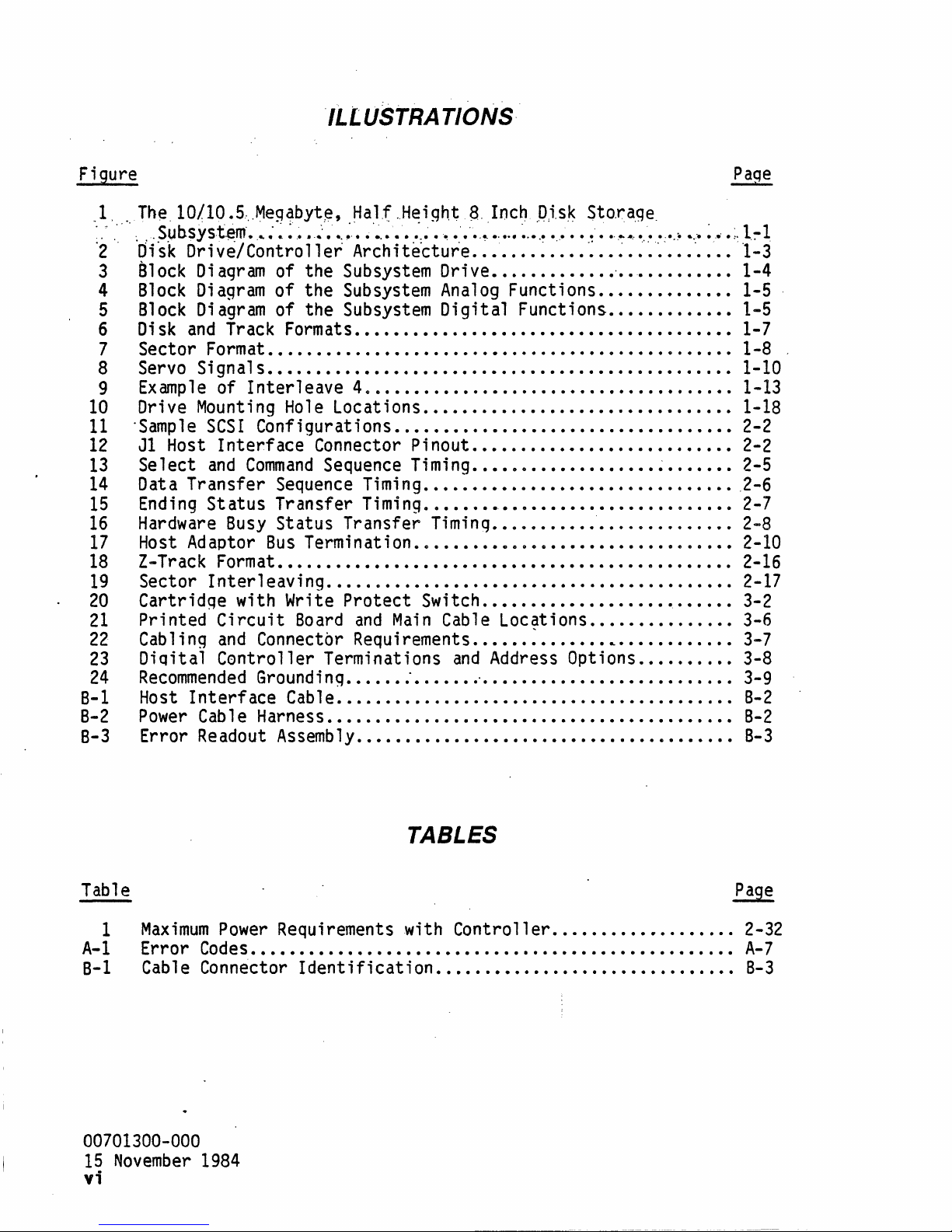
ILLUSTRATIONS"
Figure
,I. ,
The.l0/10.5,)~1egabyt,e,
.
,"
,"
.
~
"Sub.sys.t.~m·
'2'
Ofsk
3
810ck
4
Block
5
Block
6
Disk
7 Sector Format
Dri
D i agr
Diagram
Diagram
and
....
vel
Contro
am
Track Formats
8 Servo Signals
9
10
11
12
13
14
15
16
17
18
19
20
21
22
23
24
B-1
8-2
Example
Drive
'Sample
J1
Host
Select
Data Transfer Sequence
Ending
Hardware
Host
Z-Track
Sector
Cartridqe with Write
Printed
Cabling
DiQital
Recommended
Host
Power
of
Interleave
Mounting
SCSI
Interface
and
Command
Status
Busy
Adaptor
Format
Interleaving
Circuit
and
Controller
Interface
Cable Harness
8-3 Error Readout
~a1.f
,.Height
e'
~ : "~
•
"~'
e
_.~"
...
~,
....
11
er
Arch
i te'cture
of the Subsystem
of
the Subsystem
of the Subsystem
:,
~
e
""!
......... ' •••
Dri
Analog
Digital
8.
Inc~
~,.
..•....
ve
•............
Functions
Functions
'o,i.s~
,
.......................
~
.....
•...•..•......•.•...•••••.•..•.......••
.................................................
•••.......•..•...•.•...•...•......•...•.•......•
40
......................................
Hole
Locations
Configurations
Connector Pinout
Sequence
Timing
Transfer
Timing
Status Transfer
Bus
Termination
...•.................•.•........
•....••...•......•...............••
..•.....•.•......•....•..•.
Timing
..•.•...••.•.....••
.••..•.••....••..••..............
..................................
Timing
••......•..•.............
..................................
••.......•••.••..••...•••..•.•••..••••.........
...........................................
Protect
Board
and
Connectbr Requirements
Terminations
Ground i ng
Cable
•....• : •......
....................................•....
Switch
Main
..••.....•..••.....•.•....
Cable Locations
..•.•. : •..•...
and
Address Options
'. . • . . . . . . . • . . . . . . . . . . . . .
.•...............••.•..••••..•.•....••..•.
Assemb
ly
........................................
Sto,ra.ge
~
.•
~ . ~
'.~'
'.
..
. . . . . . .
.
,-
... ' ....
..•.........•.
•..........••
~
..••.•.
........•....•.
L
••••••••••••
.....•....
Paqe
----
....
~
"
••
;,
1.:-1
"1-3
•.
1-4
1-5
1-5
1-7
1-8
1-10
1-13
1-18
2-2
2-2
2-5
2-6
2-7
2-8
2-10
2-16
2-17
3-2
3-6
3-7
3-8
..
3-9
B-2
B-2
B-3
Table
1
Maximum
A-I
Error
8-1 Cable Connector
Power
Requirements with Controller
Codes..................................................
Identification
00701300-000
15
November
1984
vi
TABLES
..•......••........
•.....••..........•..•.........
Page
2-32
A-7
B-3
Page 9
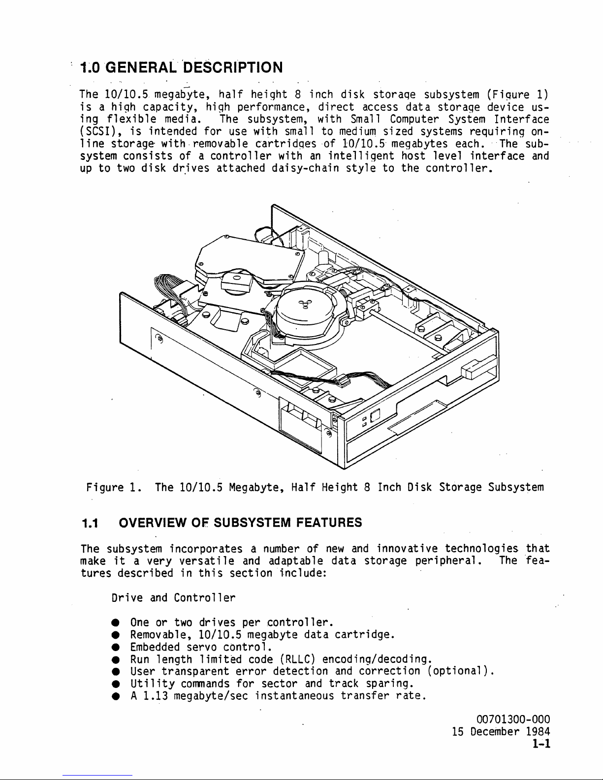
1~OGENERAL.·
The
10/10.5 megabyte, ha·lf height 8 inch disk storaqe subsystem (Fiqure
is
a high capacity, high performance,
ing
flexible
(SCSI),
line
system
up
to
is
intended for
storage
consists
two
disk
'DESCRI"PTION
media.
with· removable
of a
d~ives
The
use
controller
attached daisy-chain
direct
subsystem, with
wi~h
small to
cartridqes
with
an
·of 10/10.5· megabytes each. ··The subintelligent
access data storage device us-
Small
medium
style
Computer
System
sized systems requiring
host level
to the
controller.
interface
1)
Interface
on-
and
Figure
1.1
The
make
tures
1.
The
10/10.5
OVERVIEW OF SUBSYSTEM FEATURES
subsystem incorporates a
it
a very
described in
Drive
•
•
•
•
•
•
and
One
Removable,
Embedded
Run
Use·r
Utility
versati
this
Controller
or
two
drives per
10/10.5 megabyte data
servo
length limited
transparent
commands
• A 1.13 megabyte/sec instantaneous
Megabyte,
le
and
Half Height 8
number
of
adaptable data storage peripheral.
section include:
controller.
control.
code
error
for sector
(RLLC)
detection
and
new
Inch
and
innovative technologies
Disk
cartridge.
encoding/decoding.
and
correction
track sparing.
transfer
rate.
Storage Subsystem
The
(optional).
00701300-000
15
December
that
"fea-
1984
1-1
Page 10
;
•.
Sector
•
Data buffering
interleave
on
'capabfl ity·.
the
controller.
• Logical block addressing. .
• Comprehensive user
• Automatic
•
Au~omatic
.'
Ali
t'om
,
•
':
Autc)matt'c
•
High
•
All
at
level,
direct
startup
idle
i c
;'med
i.a" " if
'e,rrbf'.'
intelligent
current (dc)
command
set.
diagnostics.
drive
e .
half
enh
aricemenf
speed
recovery procedures>
host
interface.
power.
dwell. .
'rout i
nes ' ..
,,'
Data Cartri
•
Hard
dge
plastic
enclosure for
media
protection.
• Preformatted media.
• Convenient 8-1/2 X
11
in.
size.
• Cartridge write protect switch.
• Maintenance tracks for
cartridge-specific
tics.
A
more
teristics
1.2 PHYSICAL/MECHANICAL CHARACTERISTICS
Subsystem function
characteristics
1.2.1
The
controller
storage
storage capacity per subsystem.
the
complete description of subsystem functions
is
presented in subsection
Function
subsystem
is a hi
and
capability
assurance qf
and
operation are described in
of the drive,
gh
performanc.e
up
to
two
controller,
drives,
to systems requiring
drive-to-drive
compatibility.
1.2.
and
di
sk
storage devi ce.
the subsystem provides removable
up
to a
Data
cartridges
cartridge.
total
are interchangeable, giving
information
and
performance charac-
this
subsection,
Confi
of
20
megabytes online
and
diagnos-
as
gured with a
media
are
Major
data
S,
drive
functions of
transfer,
nee
these func.t;
is
installed
the.
subsystem include disk
host
interfacing,
ons
are
in the system, routine operation
quiring operator intervention only for
1.2.2 Drive Characteristics
The
subsystem drive contains
casting,
and
ampl
ifiers
architectural
00701300-000
15
December
drive motor, Bernoulli
some
electronic
for the head/actuator
division
1984
circuitry
of the drive
1-2
and
hand1
ed
error
-by
identification.
the subsystem contro
cartridge
all
function-a1 mechanical
plate,
head/actuator,
(read preamplifier write
and
drive motor). Figure 2
and
controller.
rotation,
is
fully
exchange.
and
head
positioning,
11
er;
automated,
components
loading
mechanism)
driver
once
and
shows
the
re-
(base
power
the
Page 11
HOST
TO HOST
POWER
(+5, +12VDC)
CONTROLLER
DIGITAL/CONTROL
..
SECTION
CPU
ROM/RAM .
HOST
INTERFACE BUFFER
FILE CONTROL LOGIC
ECC
LOGIC (OPTIONAL)
SERVO
CONTROL LOGIC
ANALOG
CLOCK
CIRCUITS
SERVO DEMODULATION
SERVO
SECTION
AND
DE1ECT
COMPENSATOR
io..--
.....
rpOWER-'
~~gF.!!~
DRIVE
INTERFACE
BOARD
READ
PREAMP
DRIVER
TO
ADDITIONAL
AND
'----
-+l_.
I
WRITE
.....
DRIVE
SPINDLE
DISK
DRIVE
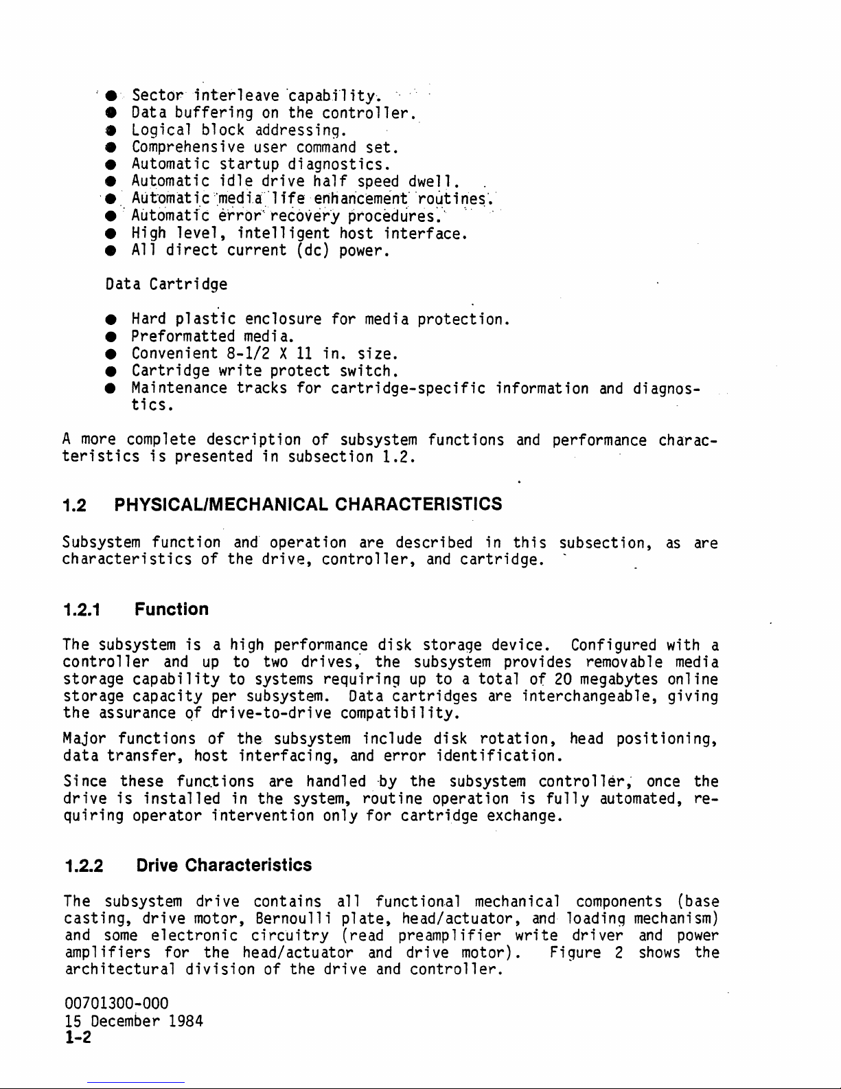
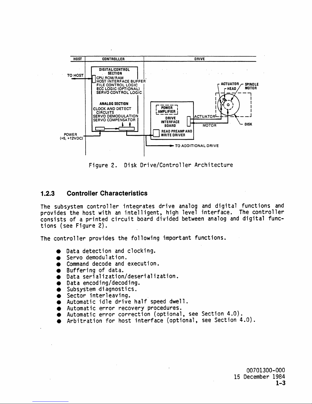
Figure 2.
Disk
Drive/Controller Architecture
1.2.3 Controller Characteristics
The
subsystem
provides the host with
consists
tions
The
controller
of a printed
(see Figure 2).
• Data detection
controller
integrates
an
intelligent,
circuit
board divided
provides the following important functions.
and
clocking.
• Servo demodulation.
•
Command
decode
and
execution.
• Buffering of data.
• Data
serialization/deserialization.
• Data encoding/decoding.
•
Subsystem
• Sector
• Automatic
• Automatic
• Automatic
• Arbitration for host
diagnostics.
interleaving.
idle
error
error
drive
recovery procedures.
correction (optional, see Section
half
interface
drive analog
high level
speed
dwell.
(optional, see Section
between
and
digital
interface.
analog
4.0).
functions
The
and
digital
4.0).
and
controller
func-
00701300-000
15
December
1984
1-3
Page 12
'.
1.2.4
The
taining
ment
cess
tion
.
. . .
The
....
. Cartridge. Characteristics.
subsystem
a single
for the
door
fnto"the
.....
disk
cartridge
flexible
media
to the
~
;s
media
'drive~
.....
.
~
. . .
a 3
mil
consists
disk.
and
a handy, transportable package for the user.
is
latched
·th4·S.
'.'
pre~entiryg.··any
..
polyester based
of'
a durable
The
cartridge
internally.
coating. Disks are preformatted at the
and
formation, sector
tracks
called the Z-tracks.
track
track boundaries are flagged
identifications,
Raw
media
when
the disks are preformatted
locations are assigned.
A
summary
1.5 of
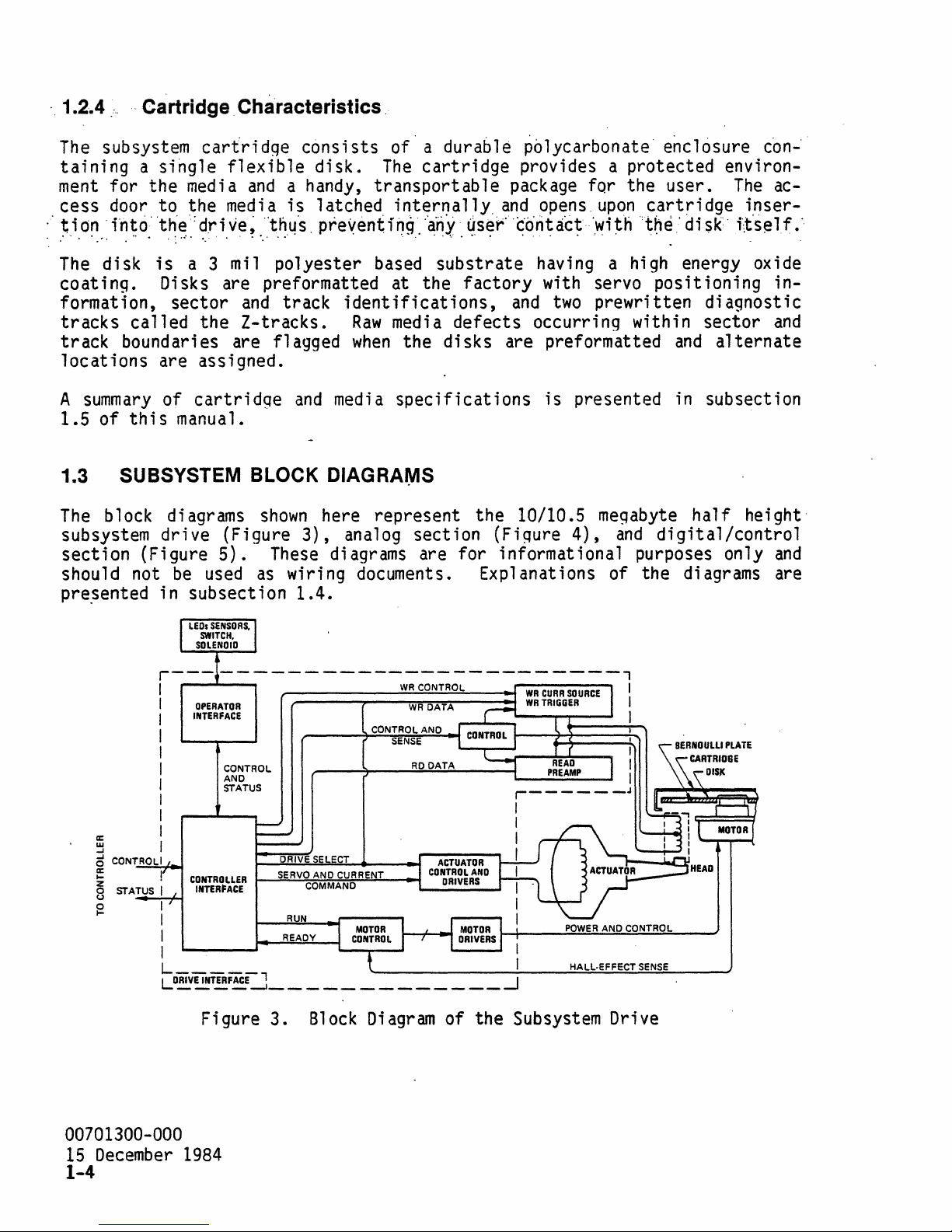
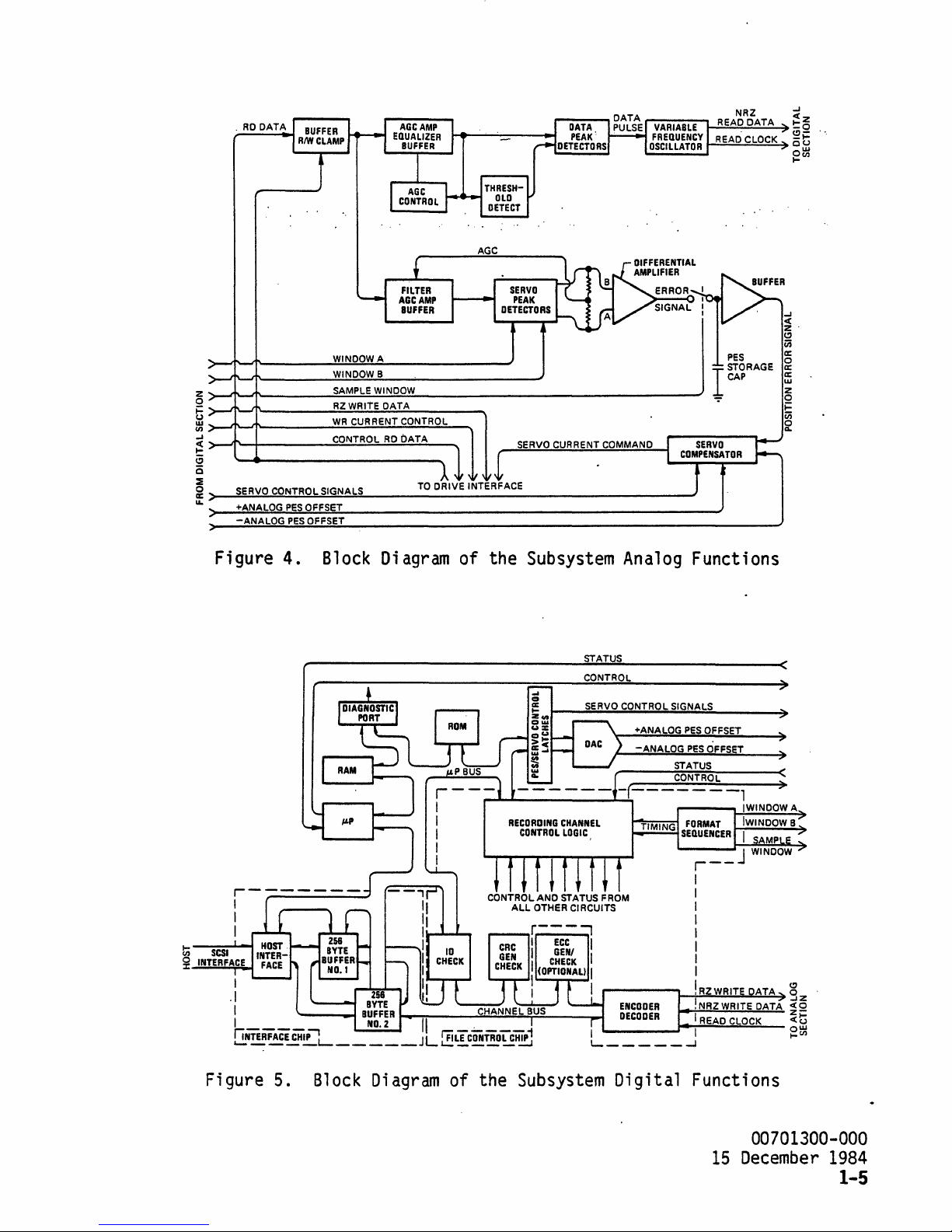
1.3 SUBSYSTEM BLOCK DIAGRAIYIS
The
block diagrams
subsystem drive (Figure
section (Figure
should not
pre~ented
of
cartridge
this
manual.
5).
be
used
in subsection
and
media
shown
These
as
here represent the 10/10.5
3),
analog section (Figure
diagrams are for informational purposes only
wiring documents. Explanations of the diagrams are
specifications
1.4.
~blycarbonate·
e~c16sure
provides a protected environ-
and
~ser·
. .
'.
....
substrate
factory
opens
co'ntact
.
-'
having a high energy oxide
with servo positioning in-
and
upon
·.~;~h
.
two
prewritten diagnostic
cartridge
the
'disk'
defects occurring within sector
and
is
presented
megabyte
4),
and
in
subsection
hal f
digital/control
c6n-
The
ac-
inser-
i,t'self.··
and
alternate
hei
ght·
and
a::
~
5
CONTROLI
~
z
o
STATUS
u
g
r---------------------------,
I
I
OPERATOR
INTERFACE
I
I
I
I
I
I
I
I
I
!
I
I
I
I
I I
__
L
LO~~T~F~E--I
CONTROL
AND
STATUS
CONTROLLER
INTERFACE
t--.=.:SE:.:..:.RV.;.;:0:-i::A~ND~C~U~RR:.:.::E.:..-NT~
~_R~U~N
- -
_,
Figure 3.
DRIVE
SELECT
COMMAND
__
~~~,
READY
_____________
Block
WR
DATA
CONTROL
_______
AND
SENSE
RD
......
'---
1---7'--"'"
DATA
Diagram
__
---'
~_--:.;.:..:.=~::.:.:....=::o:._
I
__I
of the Subsystem Drive
POWER
AND
HALl·EFFECT
CONTROL
SENSE
__
_
00701300-000
15
December
1984
1-4
Page 13
·
RD
DATA
rvARimE1!-1!R§EA~D2.Q;DA~T!:!A~
NRZ
READ CLOCK
-I
~ ~
~t
~~
AGC
-I
c(
z·
<.:)
Vi
a:
o
a:
a:
w
z
o
~
Vi
~
PES
PES
WINDOW B
~SA~M~P~L~E~W~IN~D~O~W~
RZWRITE DATA
W~R..:::C.:::.U:.:.R
R:.:,.:E::.:,N;:.,:T..;C::.;:O:.:,.:N:.:,.T.:.:,RO;;,L=---.....
CONTROL
OFFSET
OFFSET
__________________________________
RD
DATA
TO
DRIVE INTERFACE
SERVO
CURRENT COMMAND
~
~~~~~
t>-~~~--------~~~~~--------~
~
>-.JTI~1'-
-I
~~~~~--------~~~~~~--~
a
o
~
a:>-~~~~~~~~~------------------------------------------
u. +ANALOG
________
________
SERVO CONTROL SIGNALS
-ANALOG
Figure 4.
Block
Diagram
of the
RECORDING
Subsystem
STATUS
CONTROL
CHANNEL
CONTROL
LOGIC
Analog
+ANALOG
-ANALOG
STATUS
CONTROL
Functions
PES
OFFSET
PES
OFFS
T
)
Figure 5.
Block
Diagram
of the
Subsystem
Digital Functions
00701300-000
15
December
1984
1-5
Page 14
1.4· PRINCIPLES OF OPERATION
• •
.'
'"
~
•
T.
•
.'
•
Th e sub
its
sections.
system
associated
Figures 3 through 5
can
electronics
parts.
1.4.1 . Drive
The
drive (Figure
write head,
cators.
move
ator
the head, preamp1ify read data, control data
interface.
actuator,
The
major drive functions are to provide a constant spindle speed,
When a cartridge
spindle motor
speed.
plate
head,
As
on
a cushion of
which
lish a stable
interface
It
also
gre.en
the drive
board senses
signals
LED
during spinup/spindown,
when
is
the
di
penetrates through
recording environment.
the motor
be
3)
is
inserted
engaged
sk
rotates,
the
controller
brok
en
and
consists
drive
interface
and
air.
Special coupling techniques allow the read/write
motor
is
up
fu
ncti
on
all
y into th ree part s: the
the
controller
show
the functional segments of these major
of the Bernoulli
board,
and
the load lever is. turned clockwise., the
the disk spins
it
"f1 ies" in close proximity to the
an
opening in the Bernoulli
Motor
speed
and
that
and
keeps the
the disk
lights
board with analog
plate,
and
operator controls
writes,
up
control
motor
is
up
the green
spindle motor, read/
and
to a constant operating
circuitry
turning at
to speed, flashes the
LED
to speed.
dr
i
and
and
provide oper-
Bernou11
plate,
to estab-
on
the drive
1,500
on
the front of
ve
wi
th
digital
indi-
rpm.
i
If
the
di
sk
is
not accessed. over a peri
drive
or
prevent s the dr i
either
begins a steady
adjusts the motor to
ve
from
half
dwell i
time before the motor spins
Z-tracks.
causes the
When
motor
the
controller
to spin again to
track-to-track
speed
ng
on
down
to
accesses the disk
od
'of time, a timeout occurs
seeking action (drive
(dual drive configuration only). This
one
tr
ack
half
full
exces s i
speed
can
speed, or
after
ve
1 y.
be
progral1111ed
a timeout,
initiates
track corresponding with the logical address requested
Approximately 1
is
at
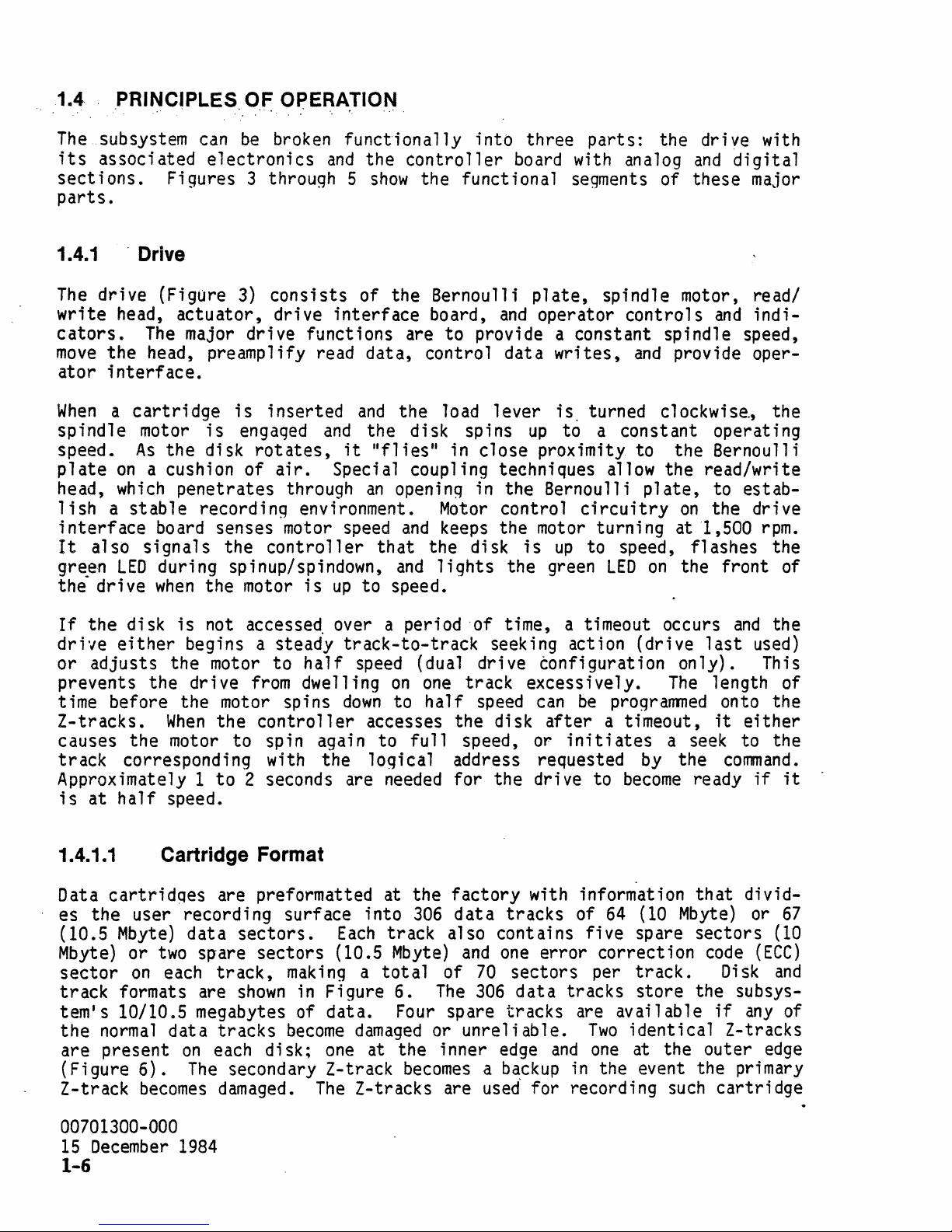
1.4.1.1
Data
cartridqes
half
speed.
Cartridge Format
es the user recording surface into
(10.5
Mbyte)
sector
track
Mbyte)
or
two
on
each
formats are
tem's 10/10.5 megabytes of data.
the
normal
are present
(Figure
Z-track
6).
becomes
to
2 seconds are
are preformatted at the
data
sectors.
sp'are sectors (10.5
data
on
The
track,
shown
tracks
each
secondary Z-track
making a total
in
become
di
sk;
damaged.
needed
Each
track also contains five spare sectors
Mbyte)
Figure 6.
Four
damaged
one
at the inner
for the drive to
306
The
factory
data
and
of
70
306
with information
tracks
one
error
sectors per
data
tracks
spare tracks are available
or
unreliable.
edge
and
becomes a backup
The
Z-tracks are used for recording
of
64
correction
Two
one
in
the event the primary
and
the
last
The
used)
1 ength of
onto the
it
either
a seek to the
by
the
command.
become
(10
ready
that
Mbyte)
if
it
divid-
or
67
(10
track.
store
code
the subsys-
Disk
if
(ECC)
and
any
of
identical Z-tracks
at the outer
such
cartridge
edge
00701300-000
15
December
1984
1-6
Page 15
·
speci.fic'
and
spare
tracks
self~test
matting'
that text
informatfon,"as'
'track
are
us'ed'
of
the
describes
lists,
to . record
the
subsystem,
Z-tracks
and
is
the
sector:'
error
speciflc'
or
special
presented
format.of
inte'rleave~
correct,ion
d'at'a'
customer
in
subsection
the
Z-tracks.).
dwe'll: ti'meout'
.status.
patterns-
required
data.
2.3.3.3.4.
,Some.
'length,:
sectors,
The
defect;-v'e
of
by .
the,
command
(Fi~ure
the
.Z-,
internal"
for
for-
18
in
10 MEGABYTE
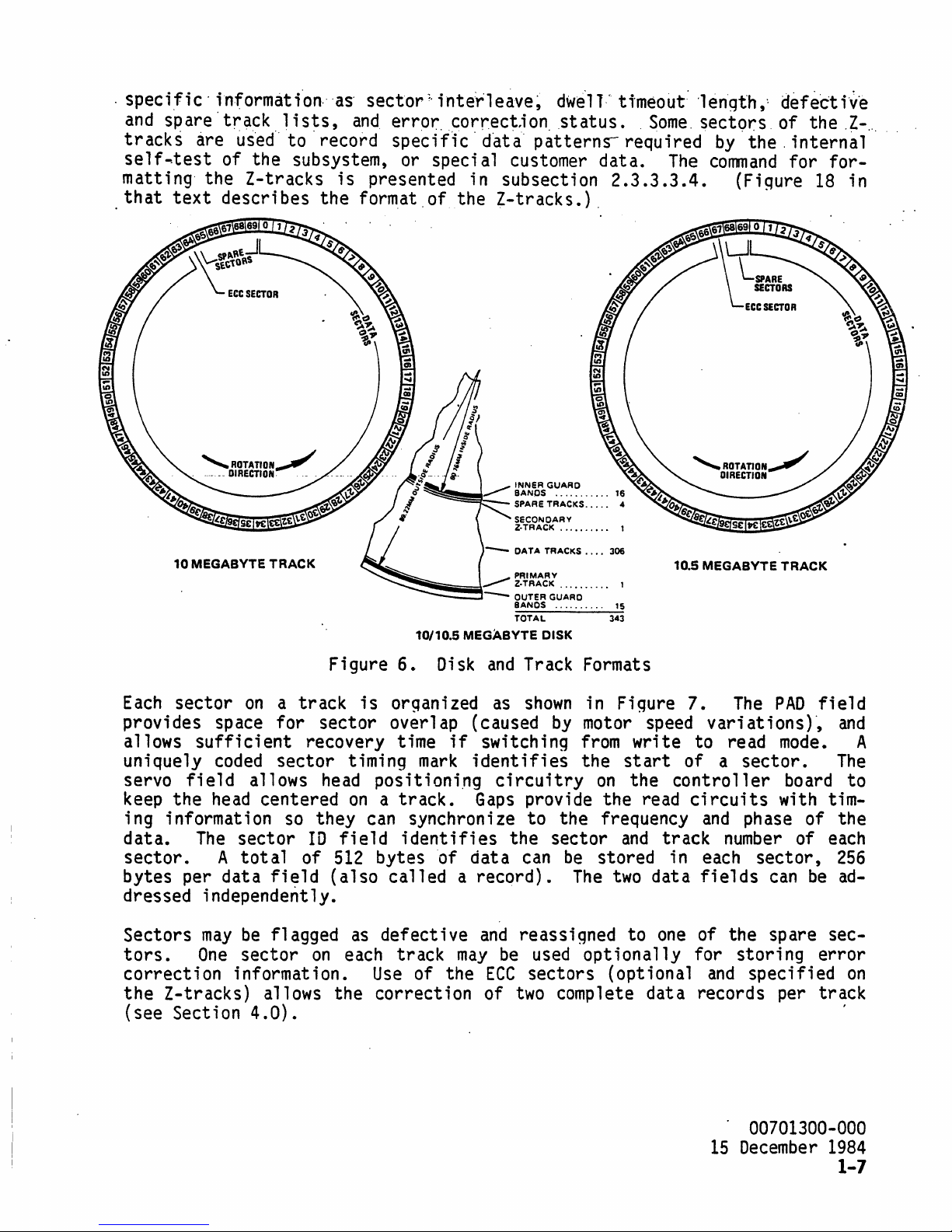
Each
sector
provides
allows
sufficient
uniquely
servo
keep
;
ng
data.
field
the
i nformat i
The
sector.
bytes
dressed
Sectors
tors.
per
independently.
may
One
correction
the
Z-tracks)
(see
Section
TRACK
on a track
space
coded
for
sector
allows
head
centered
on
so
sector
A
tot
a 1
data
be
field
flagged
sector
information.
allows
4.0).
Figure
is
sector
recovery
timing
head
on a track.
they
10
of
can synchron i ze
field
512
(also
as
on
each
the
~~=t:~:::...
~iiiiiiiiiiiiiiiii\'~
~-
10110.5 MEGABYTE DISK
6.
Disk
orqanized
overlap
time
if
mark
positioni.ng
identifies
bytes
of
called a record).
defective
track
Use
of
may
the
correction
~~~bRS
G~~~~
SPARE
TRACKS"",
SECONDARY
Z·TRACK
~~~~:~:
.• --OUTER GUARD
BANOS
TOTAL
and
Track Formats
as
shown
(caused
by
switching
identifies
circuitry
Gaps
provide
to
the
sector
dat
a can
and
reassigned
be
used
ECC
sectors
of
two
...
'"
16
4
,.,
••
',...
1
.. ,
..
. .
...
1
".",'".
in
15
343
Figure
motor speed
from
the
start
on
the
the
frequency
and
be
stored
The
two
to
opt
i ona
(optional
complete
write
the
read
track
in
data
one
11 y for
data
10.5
MEGABYTE
7.
The
variations)"
to
read
of
a
sector.
controller
circuits
and
ph
number
each
fields
of
the
stori
and
specified
records
TRACK
PAD
mode. A
board
with
ase
of
of
sector,
can
be
spare
ng
per
field
and
The
to
tim-
the
each
256
ad-
sec-
error
on
track
'
00701300-000
15
December 1984
1-7
Page 16
·
~.
PAD.---24
VFO._
SECTOR
MARK.
BYTES
.
••••
_12
SYTES} . .
TIMING
__
1SYTE
SERVO
¥~2c::.2~
GAP
FIELD
__
.27
BYTES
:~~S
}
10._4
,
',:~,c_z
BYTES
In
l"\~
"'\:
GAP
}SECTOR
...
,
I.
SYNC--l
VFO
__
ftElD'
17
BYTE
BYTES}
DATA_251
CAC
GAP
BYTES}
___ 2 BYTES'
DATA 1 FIELD
(RECORD
1)
SECTORSITRACl(
DATA
SECTORS
SPARE
SECTORS
ECC
SECTOR
70
64
5
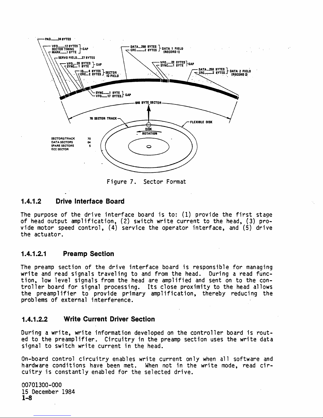
Figure 7. Sector
1.4.1.2 Drive Interface Board
The
purpose of the drive
of
head
output amplification, (2) switch write current to the head, (3) provide motor speed
the
actuator.
control,
interface
(4) service the operator
1.4.1.2.1 Preamp Section
The
preamp
write
tion,
and
low
troller
the
preampl
problems of external
section of the drive
read
level
signals
signals
traveling
from
the
board for Signal processing.
ifier
to
provide primary
interference.
board
interface
to
and
from
head
are amplified
Its
amp 1 ification,
Format
is
to: (1) provide the
interface,
board
is
responsible for
the head.
and
During
sent
on
close proximity to the
thereby reduci
first
and
stage
(5) drive
managing
a read func-
to the con-
head
allows
ng
the
1.4.1.2.2
During a
ed
to
the preamplifier.
signal
to
On-board control
hardware conditions
cuitry
is
Write Current Driver Section
write,
write information developed
Circuitry
switch write current in the head.
circuitry
have
been
constantly enabled for the selected drive.
00701300-000
15
December
1984
1-8
on
the
controller
in the
preamp
section uses the write data
enables write current only
met.
When
not in the write
when
board
all
mode,
is
rout-
software
read
and
cir-
Page 17
A
single-chip
cation
It
also
..
med1.a.
microprocessor'provides commutation of the mofor phases,
of
motor speed within
controls'
while .:the
the
mq.tor
latch
..
i.s
.spjnnJt1g
limits,
and
pin, solenoid,
•.
:
motor speed control
which
inhibits
unloading
to
1500
of
indi-
rpm.
the
1.4.1.2.4
The
on-board microprocessor' also senses
the
green
pushbutton (which
lates
1.4.1.2.5 Actuator Driver Section
control
Actuator
from
1.4.2 Controller Board
The
the
controller
digital
1.4.2.1 Analog Section
The
main
is
synchronous with
disk,
for
(2)
head
Operator Interface Section
LEO
when
lines
control
controller
initi
and
board
the
that
driver
board
is
motor
ates
interface
to
comprised
section.
purposes
filter
positioning,
of
and
the
the
shape
and
analog
frequency
the
(4) provide servo loop compensation.
is
spinning
motor spindown).
circuits
direct
section
read
with
use
current
of
two
and
data,
the
motor has been loaded,
up
or
down,
It
also monitors
the
controller
the
Servo Current
to
the
actuator.
areas:
are
to
the
(1) provide a read clock
phase of the
(3)
interpret
and
board.
analog
data
flashes
polls
the
and
Command
section
console
manipu-
signal
and
the
that
coming
from
the
servo information
1.4.2.1.1
Read
signed
and
re 1 at i ve
data
signals
to
recover
threshold
strength
During a read
negative
After
peaks
shaping
Read
Channel
are buffered
the
detect
'of
process,
that
and
gain
output uniform pulses
oscillator
synchronous clock
nonreturn
(VFO)
to
zero
phase locks to
that
(NRZ)
decoded, but are in a
digital
section.
original
circuits
the
read signa 1 .
the
read
correspond
control,
for
each
is
used to
·format.
TTL
form
and
shaped through
written
data.
are included
data
the
lines
to
flux
the
peaks are fed
peak
encountered. A
trailinq
transl
At
this
that
can
be
Automatic gain
to
compensate
contain a
reversals
edqe of
ate
the
point
used
the
easily
a'
series
series
recorded
into
the
data
data
of
circuits
control
for
changes in
of
positive
on
peak
detectors
variable
pulses,
pul
ses
bits
by
the decoder in
providing a
into
have not
00701300-000
15
December
de-
(AGC)
the
and
the
disk.
that
frequency
standard
been
the
1984
1-9
Page 18
·1-
•.
4.2.1.2····
Servo~
Error Decoding
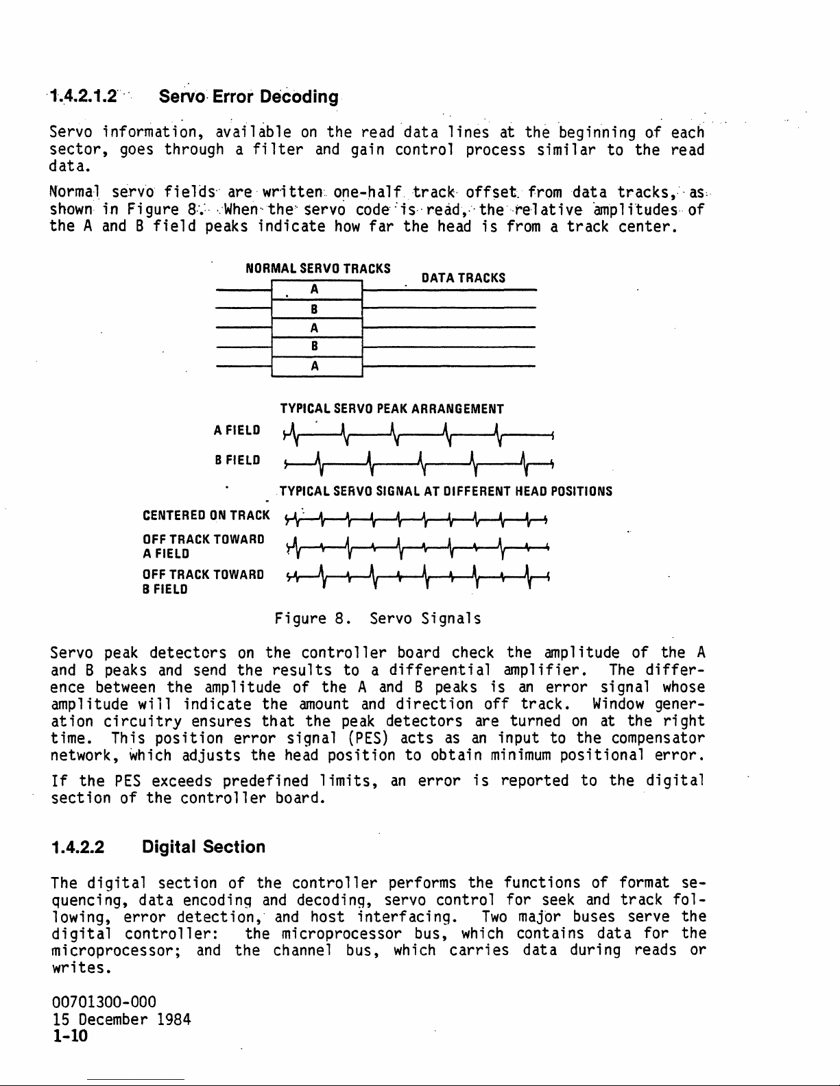
Servo
sector,
data.
N·orma·l
shown:
the
A and B
information,
goes
se.rv·o·
in
through a filter
fields"
Figure
CENTERED
8:.:· · ..
field
av:ailable
are·
wr·itten·
When··the'·
peaks
A
B
ON
indicate
NORMAL
FIELD
FIELD
TRACK
on
and
servo
SERVO
A
B
A
B
A
TYPICAL
~
~
TYPICAL
the
read
'data
gain
..
one-half.
how
TRACKS
SERVO
~
control
code':is,·read,:·the'··re·lative
far
the
PEAK
\
\
SERVO
SIGNAL
lines
process
track·
DATA
ARRANGEMENT
~
AT
off$et.
head
is
TRACKS
\
\
DIFFERENT
~
at
the
similar
from
from a
Ar
HEAD
'begin'ning
to
data
amplitudes
track
POSITIONS
of
each'
the
read
tracks,.',
center.
..
as:·
of
Servo peak
and B peaks
ence
amplitude
ation
time.
network,
If
section
between
circuitry
This
the
PES
will
which
of
1.4.2.2
The
digital
quencing,
lowing,
digital
mi
croproces
writes.
error
controller:
OFF
TRACK
A
FIELD
OFF
TRACK
B
FIELD
detectors
and
the
position
exceeds
the
TOWARD
TOWARD
on
send
indicate
ensures
adjusts
controller
the
amplitude
error
predefined
the
Digital Section
section
data
sor;
encoding
detection,
and
of
the
the
A
,
rAv
Yr--\
Figure
the
results
of
the
that
signal
head
board.
the
controller
and
and
microprocessor
ch anne 1
8.
contro
the
amount
the
peak
position
limits,
decoding,
host
f
•
~
f
r
\
Servo
11
er
to a differential
A
and
and
(PES)
interfacing.
bus,
,
.,
\
,
,
board check
direction
detectors
acts
to
an
performs
servo
wh
~
f
r
\
Signals
B peaks
as
obtain
error
control
bus,
i ch
carri
the
which
,
•
•
..
f
\
the
amplifier.
is
off
are
an
input
minimum
is
reported
functions
for
Two
es
f
~
•
~
amp 1 itude
an
error
track.
turned
to
positional
seek
major
contains
dat a duri
The
signal
Window
on
at
the
compensator
to
the
of
and
buses
data
ng
of
the
differ-
gener-
the
error.
digital
format
track
serve
for
reads
A
whose
right
se-
fol-
the
the
or
00701300-000
15
December
1984
1-10
Page 19
The: di'gital 'controller'uses"
(one, for
mi
croprocessor.
are explained in
The
microprocessor
only
memory
ry monitors the drive
microprocessor.
field
outputs
The
microprocessor monitors the host
cepts
mand
execution,
tered along the
is
stored, available
file
,control
The
this
(ROM),
The
programmable
status
and
decodes
information to the diaqnostic port.
and
way
an~
funct ions as'soci ated with these three
subsection.
circuitry
random
~ccess
status
microprocessor also monitors
options, controls the
command
and
returns ending
are flagged to the host
to
the host via a
two'
custom
one
..
is
memory
lines
for host, ,interface) ,as
composed
metal oxid'e:semiconduct'or'
of a
(RAM),
and
controls drtve
Z80-A
and
bit
idle
interface,
drive half
recognizes a
parameter bytes, schedules
status
to the host.
and
REQUEST
SENSE
specific
(Mos)"chip's'
,well
major
,as
'components
microprocessor, read
I/O
ports.
This
initialization
switches
speed
that
feature,
selection,
and
control s
Any
errors
error
information
command.
a
Z80A
circuit-
via the
indicate
and
ac-
com-
encoun-
1.4.2.2.2
To
initiate
information
causes the
offsets,
the
Servo Control
a seek operation, the microprocessor introduces position
and
current
head
to
move
the proc.essor
offsets
off
can
tion of the head.
1.4.2.2.3
The
host-to-controller
includes
flop
mode
Interface Circuitry
two
256
so
byte
that
FIFO
data
interface
buffers.
can
data transmitted to the host.
Each
KNQWLEDGE
during the
commands,
lows
host
transfer
(REQ-ACK)
command
the microprocessor enables a
high
speed
interface
between
controller
handshake.
and
status
transfers.
is
presented in Section 2.0 of
into the track following servo loop,
tr'ack.
By
contro,lling the
amount
control the acceleration, velocity,
is
centered
These
be
accepted
and
host
The
microprocessor manipulates the
phase.
During
hardware
A detailed explanation
around a custom
buffers are controlled in a
from
the disk Simultaneously with
is
accompanied
the data
transfer
this
manual.
phase
and
by a REQUEST-AC-
mechanism
description of the
'
of
and
timing of
LSI
chip
READ
error
which
and
posi-
that
flip-
handshake
or
WRITE
that
al-
1.4.2.2.4
The
file
codes
and
compares
File Control Circuitry
control
decodes,
track
circuitry
seri
and
sector
manipulates signals according to
and
gathers
and
reports
is
centered
ali
zes and, deseri ali zes, generates
IDs,
maintains synchronization with the disk,
commands
error
status.
around a custom
received
from
MOS
chip
and
that:
en-
check s CRC,
the microprocessor,
00701300-000
15
December
1984
1-11
Page 20
The
subsystem uses
, , packed'
host
special
':'
Each"rO"
"tect'iori
the
troller,
an
host,
retries
on
to
disk,
error
but
the
the
code
marks
and
dataar'~a'
'pt.i'rpo·s'es.
are
the data
is
detected, the 'incorrect data
retri
will
be
the host. Optional
a,
run
length limited,code
di
sk.
on
The
and
format requ i red
the disk
,'orf'~he:disk'
encoder/decoder
that
allow
"Th'e"CRC'byt"es','qenerated
appended
and
es
wi
attempted in
to the data.
CRC
are loQical1y manipulated to
11
be
attempted to execute the
ECC
circuitry
normal
also
that
trans
by
the cont
bit
and
byte synchronization.
is··fQri'q~;ed··,by'a·
as
As
the data
wi
operation before
may
be
alluws
1 ates
ro
11
.CRC,
dat~
datarecei
er.
f.ield.·fb.~,:·~rro'r'.:·de~
~o
be
ved
from
It
also detect s
tightly
the data bits' are written to
bits
11
not
invoked (see Section
are read to the con-
check
be
command
error
for
errors.
transferred
correct
status
is sent to
1
4.0).
to' the
y.
the
If
Si
x
Before
compared
tomer data will
A unique
tection
any
read or write operation, the
with
mark
of these
that
is
of the
be
accidentally overwritten or mistaken for desired data.
tarqet
written at several places in
marks
enables the
ID
of the sector under the
sector. This function ensures
file
control format sequencer to maintain
synchronization with the disk.. This sequencer
signals
At
the beginning of
croprocessor. This information
ing to
encoder or decoder.
by
the microprocessor. Serious
1.4.3 Interleaving
A
number
Some
correction option. Interleaving
described in
required
by
the analog
each
(1) enable write
As
of important
of these are data
this
subsection.
sector,
gates,
controller
an
operation
is
used
(2)
set
board.
in conjunction with the format timbus
directions,
er.rors occur, they are latched for
and
Error
factors
transfer
errors
Correction Code
control the performance of the subsystem.
rate,
See
will cause the operation to abort.
latency,
and
how
it
affects
Section 4.0 for
each
register
sector
in
turn manipulates control
is loaded
interleaving,
system performance
ECC
impacts.
on
and
that
the disk.
by
(3)
select
later
and
retrieval
the
head
no
the
error
is
cus-
De-
mithe
;s
1.4.3.1
Maximum
ever, the actual
hardware
interleave
does not
nearly
determines
, Interleaving
data
transfer
rate
and
software plus the interleave
selection
affect
as
much
how
the performance of single sector or' sinqle record
as
quickly the drive will
rate
achieved
can
does
latency, but for
data.
is
Interleaving
ance
the
00701300-000
15
when
working
maximum
December
a system desiqned to achieve the hiqhest possible perform-
with host systems that cannot
transfer
1984
rate
1-12
of the subsystem
by
the host system
is
selected.
dramatically
de~rade
multi-sector
be
ready to
of the disk subsystem.
1.13
meQabytes/second.
is
a function of the host
Poor
choice in the
How-
performance. Interleaving
transfers
bursts,
transfer
transfer
Durinq
the next block of
data
interleaving
as
rapidly
a data read, for
as
Page 21
,examp'1.e'~:
with
host
Having
have
" trans.fe,rred
be'-on1y
',f'
the'
host'
its
two
256
bytebuffers~
had
emptied
no
place to put the data
one
to complete a
•.
,Under
t2,800
byte·s/sec.
,these conditions!J,the effective·' data,
co'u1
d ' trao'sfer' .dat'a at 250 ,000
would,
of the buffers,
full
revolution
",
read 512 bytes 'of data,:
would
from
this
(40
.
bytes/sec~
be
ready to read the next sector.
the"
and
before the
next sector, the disk then
msec)
before the data could
transfer
rate
drfve~
would
be
wou.1d,
Interleaving
logically
mance
buffer
that
factor
by
is
the logical sectors are physically next to
of 2 will leave
interleave factor
can
minimize
such
loss in performance
(not physically) adjacent sectors.
allowing additional time for the host to
needed
again.
one
specifies
An
interleave factor of 1
sector
the
between
number
of sectors
the next.
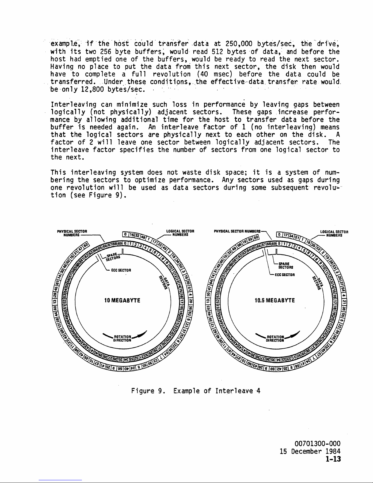
This interleaving system
does
not waste disk space;
bering the sectors to optimize performance.
one
revo 1 ut i
tion (see Figure
PHYSICAL
SECTOR
NUMBERS-~
on
wi
11
9).
be
used
as
dat a sectors duri
Thes~
transfer
each
logically
from
Any
sectors
ng
by
leaving
gaps
gaps
,increase perfor-
data before the
(no
interleaving)
other
on
the disk. A
adjacent sectors.
one
logical sector to
it
is
a system of
used
some
as
gaps
subsequent
between
means
The
num-
during
revo
1u---
10
MEGABYTE
Figure 9.
Example
of Interleave
10.5
MEGABYTE
,4
00701300-000
15
December
1984
1-13
Page 22
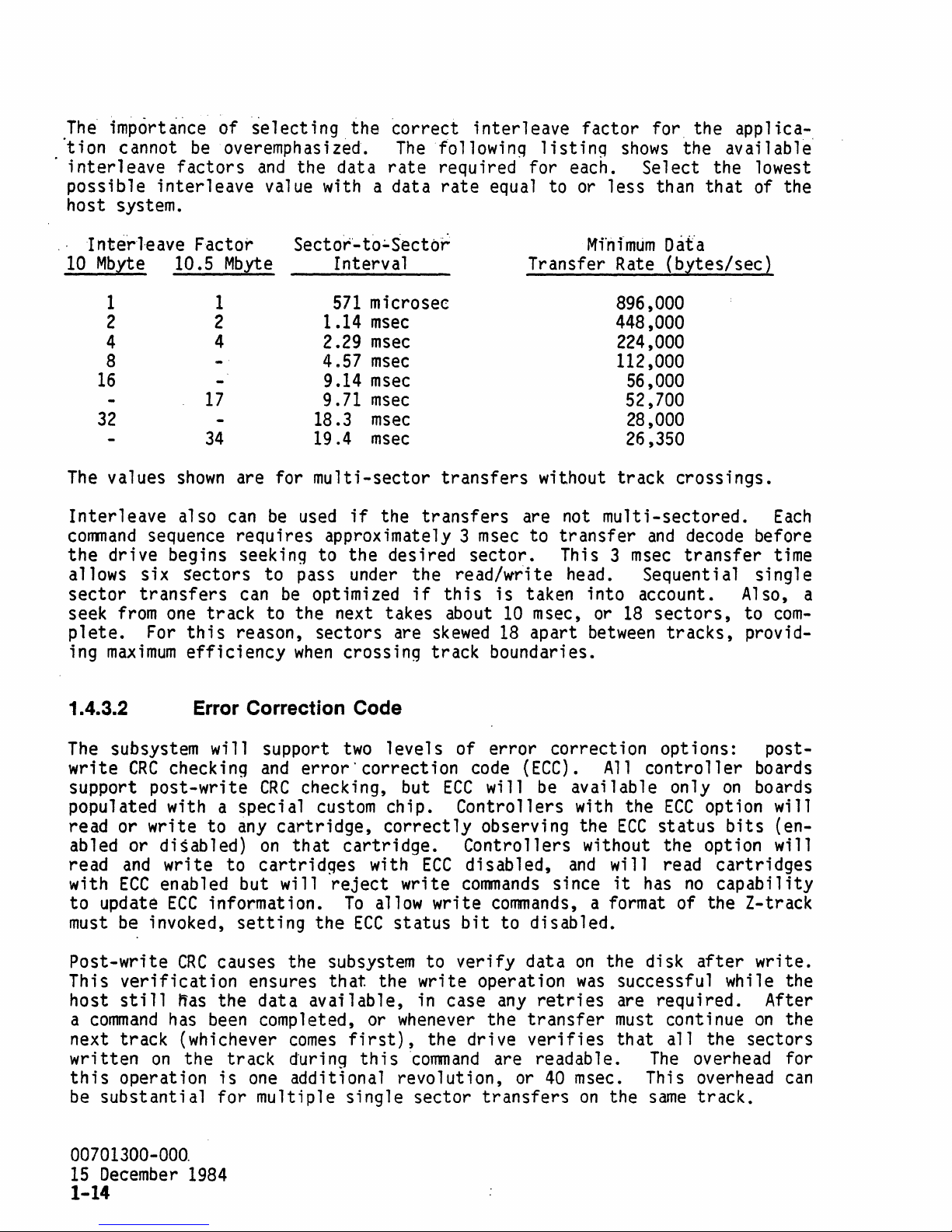
Th~
imp6rt~~ce
·tion cannot
i
nterl
possible
eave
interleave
host system.
of
be
overemphasized.
factors
~electing
the
~orrect
Therollowinq
and
the data
rate
value with a data
interleave
factor
listinq
required for each.
rate
equal to or
less
for"
shows
Se 1 ect
than
the applica-
the available"
the lowest
that
of the
""
I nterleave Factor
10
Mbyte
1
2
4
8
16
32
The
values
Inter
1 eave also
command
the
drive begins seeking to the desired
allows six
sector
seek
from
plete.
ing
maximum
10.5
shown
sequence requires approximately 3
sectors
transfers
one
For
this
efficiency
Mbyte
1
2
4
17
34
can
Sector"-
are for
be
18.3
19.4
multi-sector
used
to:"S"ector
Interval
571
microsec
1.14
2.29
4.57
9.14
9.71
msec
msec
msec
msec
msec
msec
msec
if
the
transfers
transfers
msec
sector.
to pass under the read/wr"ite head. Sequential single
can
be
optimized
if
this
track to the next takes about
reason, sectors are
when
crOSSing
skewed
track boundaries.
Mfri
i"
mum
D
afa
Transfer Rate
896,000
448,000
224,000
112,000
(bytes/sec)
56,000
52,700
28,000
26,350
without track crossings.
are not
to
is
taken into account. Also, a
10
msec, or
18
apart
mu
1 t
transfer
This 3
18
between
i-sectored.
and
decode
msec
transfer
sectors,
tracks,
to
provid-
Each
before
time
com-
1.4.3.2
The
subsystem
write
CRC
support
populated with a special
read or write to
ab 1 ed
read
with
to
must
or
and
ECC
update
be
Post-write
This
host
a
verification
still
command
next track (whichever
written
this
be
00701300-000.
15
operation
substantial
December
Error Correction Code
wi
11
support
checking
post-write
and
error'
CRC
checking, but
custom
any
cartridge,
dis
ab 1 ed)
write to
on
th at
cartridges
enabled but will
ECC
information.
invoked,
CRC
setting
the
causes the subsystem to
ensures
~as
has
the data
been
completed, or
available,
comes
on
the track during thiscomnand are readable.
is
one
additional revolution, or
for
multiple single sector
1984
1-14
two 1 eve
correction
chip. Controllers with the
correctly
cartri
with
reject
To
allow write
ECC
that
the write operation
first),
1 s of
error
code
ECC
will
observing the
dge. Contro
ECC
disabled,
write
commands
commands,
status
bit
verify
in case
whenever
any
the
the drive
transfers
correct i on
(ECC).
be
11
ers
All
available only
wi
thout the opt i
and
since
a format of the Z-track
to disabled.
data
on
the disk
was
retries
transfer
verifies
40
msec.
on
opt ions: post-
controller
ECC
ECC
status
will read
it
has
no
option will
after
boards
on
boards
bits
on
(en-
wi
cartridges
capability
write.
successful while the
are required. After
must
that
the
continue
all
the sectors
The
overhead for
on
This overhead
same
track.
the
can
11
Page 23
t~5:·:·'
. SUBSYSTEM . SPECIFICATIONS
Capacity, performance, rel i
tion,
subsection.
.
M~yte
"
fneftherof
system without loss of user data.
imum
requirements.
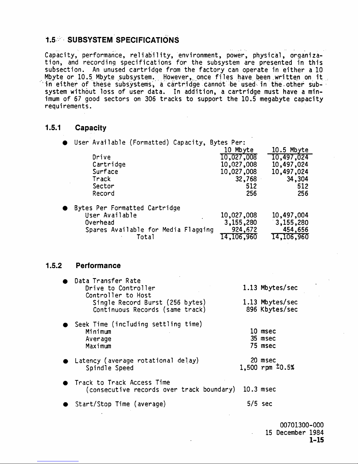
1.5.1
and
recordin9
An
or
10.5.
of
67
Capacity
•
User
• Bytes Per Formatted Cartridge
Mbyt,e
these
good
Available (Formatted) Capacity,
Drive
Cartri
Surface
Track
Sector
Record
User
Overhead
Spares Available for
specifications
unused
..
,subsystem. ,
subsYs.terris,~·
sectors
dge
Available 10,027,008 10,497,004
abi 1 ity,
cartridge
on
306
Total 14,106,960
'environment,
for the subsystem are presented in
from
~owever,
a"ca:rt'rJdge .cannot·:be·
tracks
Media
the factory
...
Orlce
In
addition, a
to support the 10.5 megabyte capacity
Flagqing 924,672
power,
can
fi
1 es
h~ve,~een.
cartridge
Bytes
Per:
10
Mbyte
10,027,008'
10,027,008
10,027,008
32,768 .
3,155,280
physical, orga'ni
operate
used:,
in 'the', other
must
512
256
in
either
wri
t.t~,n
have a min-
10.5
10,497,024
10,497,024
10,497,024
34,304
'3,155,280
454,656
14,106,960
on
'
Mbyte
512
256
za-'
this
a
10
it
sub.;
,
1.5.2
Performance
Data
•
•
•
•
•
Transfer Rate
Drive to Controller
Controller
Single
Continuous Records
Seek
Latency (average
Track
St
Time
Mi
ni
mLlTl
Average
Maximum
Spindle
to
(consecutive records over
artl
Stop
to
Host
Record
(including
Speed
Track
Ti
Access
( average)
me
Burst
rotational
(256
(same
settling
Time
bytes)
track)
time)
de
1..ay)
track boundary)
1.13 Mbytes/sec
1.13 Mbytes/sec
896
Kbytes/sec
10
msec
35
msec
75
msec
20
msec
1,500
10.3
SIS
rpm
msec
sec
15
!0.5%
00701300-000
December
1984
1-15
Page 24
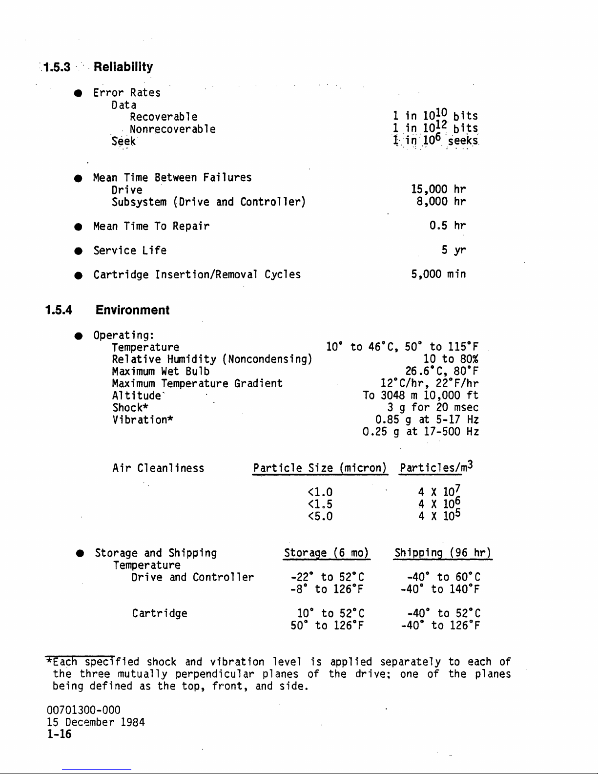
",1'.5.3
' " " Reliability
• Error Rates
Data
Recoverable
Nonrecoverable
'Seek
,
..
"
•
Mean
Time
Drive
Subsystem
•
Mean
Time
To
Between
"
(Drive
Repair
Failures
and
Controller)
1 in
1 in
1-.'i;;.'
10
1012"
10
..
~
':.'
.' .
15,000 hr
8,000 hr
10
bits
bits
6
"seeks"
Oe5
hr
•
Serv-i
ce Life
• Cartridge Insertion/Removal Cycles
1.5.4 Environment
• Operating:
Temperature
Relative Humidity (Noncondensing)
Maximum
Maximum
Wet
Bulb
Temperature Gradient
AltitudeShock*
Vibration*
Air Cleanliness
Particle
5 yr
10°
to
46°C,
5,000
500 to
26.6°
10
min
115°F
to
C,
80°
12°C/hr, 22°F/hr
To
3048
3 9
m 10,000
for
20
msec
0.85 9 at 5-17
0.25 9
at
17-500
Size (micron) Particles/m
<1.0
<le5
<5.0
4 X
4 X
4 X
7
10
6
105
10
80%
F
ft
Hz
Hz
3
• Storage
and
Shipping
Temperature
and
Drive
Controller
Cartridge
*Each
the
being defined
00701300-000
15
specified
three
December
shock
and
mutually perpendicular planes of the drive;
as
the top,
1984
1-16
Storage
_22°
_8°
50°
vibration level
front,
and
side.
10°
(6
mo)
to
52°C
to
126°F
to
52°C
to
126°F
is
applied separately to
Shipping
_40°
_40°
_40°
_40°
one
(96
hr)
to
to
to
to
0
60
e
140°F
52°C
126°F
each
of
of the planes
Page 25

-'-R:el
ative'
H'Umfdit}/Jnon'conden'sino}
'10
::to".'
90
"%'
Shock*
Vi
brat i on*
1.5.5 Power
(four drops)
• Voltage (see subsection
V,o
1 tage
5
±5%
12
1:5%
•
Power
(max
continuous
Continuous
1.5
amps
rms
r i
1.5
amps
rms
r i
power
2.4,
Table 1 for
with
pp
1 e
max
with
pp
1 e
max
Max
30
mv
60
mv
Current
consumption tn watts)
details).
(amp's)
Instantaneous
1.5
amps
120
mv
.
ripple
3
amps
cycle 300
p-p
ripple
40'q
for
1 • 3 g at 5 -
2
gat.
5-,
~l-
:·~t
'60-500
peak
with
p-p
max
peak,
25%
mv
max
15
ms~c
27
27-60
duty
Hz
,Hz
Hi
First
Additional Drive
1.5.6 Physical
Drive with Controller
25
10
watts
watts
Dimensions
• Drive**
Height
Width
Depth
• Front Panel Including
Height
Width
Depth
*Each
specified
shock
Load
and
vibration level
Lever
59.00
217.00
305.00
59.00
217.00
27.02
is
applied separately to
mm
mm
mm
mm
mm
mm
2.32
8.54
12.01
2.32
8.54
1.06
each
the three mutually perpendicular planes of the drive; the planes being de-
as
fined
**Without
the top,
front
panel
front,
and
and
side.
with or without
controller.
in.
in.
in.
in.
in.
in.
of
00701300-000
15
December
1984
1-17
Page 26

• . Cartri'dge
Height
Width
Depth
18.00
209.00
280.00
mm
mm
mm
0
..
71
8.23
1.1.02
in.
in.
in.
FJexible.Disk
•
Weights
Drive with Controller 2.95
•
•
•
The
controller
the
dimensions
Drive without
Cartridge
board
shown
Controller 2.35
is
mounted
below
Physical dimensions of the
mounting holes (Figure 10),
ette
drive.
•
Vertically
The
box
(on
can
be
eith~r
• Horizontally (load lever at
29.21.:!::
lMM
(1.15.:!::
0.039 IN.)
t----
...
completely within the drive casting. Thus,
relate
dri.e
box,
conform
mounted
side)
MOUNTING HOLES
203.2.:!::
(8.00.:!::
- - -- -
Diameter Thickness
.'
198.0
····708·irL
to a drive with or without a
including the location
0.59
mm:'
kg
kg
kg
'0.08
0.003'
7.9 lb
6.3
1.3
controller.
and
size
of
to those of the industry standard disk-
in
any
of the following
positions.
right)
(8-32, 8 PLACES)
t
59MM
(2.32 IN.)
t
0.5
MM
0.0197 IN.)
--
--
---
..
'mm
in''::
lb
lb
its
189.72
MM
(7.47 IN.)
..
13.64
MM
•
(0.504IN.1
-
9.52MM
....
(0.375 IN.) (12.0 IN.)
Figure 10. Drive
00701300-000
15
December
1984
1-18
~
-25.4MM
...
I
I
(1.COIN.)
Mounting
88.9
305MM
MM
(3.50 IN.)
Hole
-
Locations
217M
M
N.) (8.541
Page 27

,1-.5.7--
-,: Organization'
•.
Cbnfig~ration'
• Formats
Drives per Controller
Cartridges per Drive
Recording Surfaces per Flexible
'Formatt.e'd:
- 'per Surface '.. . . .
Formatted (user available) Sectors
per Track
Records per
B~tes
Surface
Outer
Data
Z-Tracks
Spares,
Inner
{us~r·.availaqleY
Sector
per
Record
(No.
tracks)'
Guard
for
Guard
Bands
Field Flagging
Bands
Total
Tr'ackS'"
Disk
10
Mbyte'
10.5
Mbyte
1 or 2 1 or 2
1 1
1 1
306
64
2 2
256 256
15
306
2
4
16
343
306
306
343
67
15
2
4
16
1.5.8
•
•
•
•
•
Tracks
Sector
Recording
Encoding
Recording Density
Flux
Track
Areal
Density
(No.
Data
ECC
Spares, for Factory
Field Flagging
(No.
Data
Servo
CRC
ID
VFO,
Method
Density
Density
sectors)
bytes)
(2 Records of
Timing
Mark,
and
Total
256
Sync,
Total
bytes each)
and
PAD
64
1
5
70
512
27
6
4
99
648
24,000 bpi
18,000
·67
1
2
70
512
27
6
4
99
648
RLLC
fci
300
tpi
7.2 Mbits/in.2
00701300-000
15
December
1984
1-19
Page 28
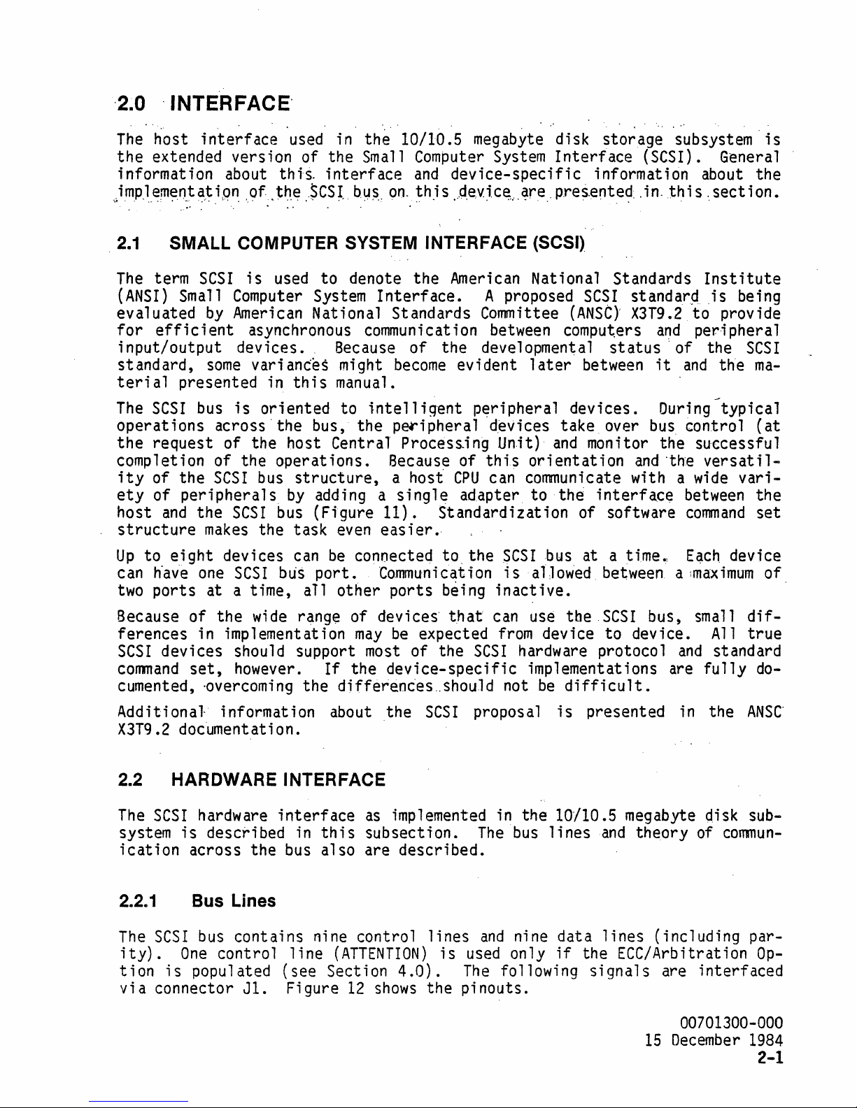
'2.0 ,INTERFACE'
The
host i nterf
the
extended version
information about
)m.pJ,.~m~?_t
~,~
ace 'used in
,i
p~
,,9f>
of
thi-s,
t~,.e
.
.SC.S~.,
the
10/10.5 megabyte di
the Small Computer System
interface
by~"
and
on"
~h.i
device-specific
s
..
,ct.evJ,c~."
~re.,
sk
storage
Interface
subsystem'
(SCSI). General
information about
p.res.ente~~
. i
n.
th
is,.
sect
i on.
is
the
2.1
The
(ANSI)
evaluated
for
input/output
standard,
terial
The
operations
the
completion
ity
ety
host
structure
Up
can
two
Because
ferences
SCSI
conmand
SMALL COMPUTER SYSTEM INTERFACE
term
SCSI
;s
used
Small Computer System
by
American National Standards Committee
efficient
asynchronous communication between computers
devices.
some
variances
presented in
SCSI
request
of
of
to
h'av'e
ports
bus
across
of
of
the
SCSI
peripherals
and
the
makes
eight
devices can
one
at
of
the
is
oriented
'the
the
the
operations.
bus
SCSI
bus (Figure
the
SCSI
bUs
a time,
wide
in implementation
devices
set,
should support most
however.
cumented, -overcoming
to
this
bus,
denote
Because
might
manual.
to
intelligent
the
the
American National Standards
Interface.
of
the
become
p~ipheral
evident
p~ripheral
A proposed
developmental
later
deVices
host Central Process-ing Unit)
structure,
by
adding a
task
even
be
port.
aTl
other
r~nge
the
of
If
the
differenc'es
Because
a host'
single
11).
easier.,
connected to.
Communication
ports
devices'
may
be
of
device-specific
of
this
CPU
can communicate with a
adapter
Standardization
the
SCSI
is
being
that
expected
the
..
shou.1d
inactive.
can use
from
SCSI
not
hardware protocol
orientation
to
al]owed between a
implementations are
(SCSI),
(ANSt)'
devices.
take
and
the
of
bus
the
device
be
difficult.
Institute
SCSI
between
standarq ,is being
X3T9.2
status:
to
and
peripheral
of
it
and
the
the
During
over
bus
control
provide
SCSI
ma-
typical
(at
monitor the successful
and
·the
versatil-
interface
software
at
a time.:
wide
between
command
E~ch
vari-
the
set
device
:maximum
SCSI
to
bus, small
device. All
and
standard
fully
diftrue
do-
of
Additional
X3T9.2
~2
The
HARDWARE INTERFACE
SCSI
system
ication
2.2.1
The
SCSI
ity).
tion
via
is
connector
information about
documentation.
hardware
is
described in
across
Bus Lines
bus
contains
One
control
populated
the
Jl.
interface
bus
(see
Figure
nine
line
the
as
implemented in
this
also
subsection.
are
described.
control
(ATTENTION)
Section
12
4.0).
shows
SCSI
lines
;s
the
proposal
the
The
bus
and
nine
used only
The
following
pinouts.
is
presented in
the
ANSC'
10/10.5 megabyte disk sub-
lines
data
if
and
theory
lines
(including
of
comnun-
the ECC/Arbitration
Signals
are
interfaced
par-
Op-
00701300-000
15
December
1984
2-1
Page 29

COMPUTER
SIMPLE
SYSTEM
BASIC
COMPUTER.
TWO
CONTROL
UNIT
SYSTEM
COMPUTER
HOST
UP
TO
EIGHT
ANY
COMBINATION
ADAPTER
SCSI
COMPUTER
HOST ADAPTER
SCSI
BUS
DEVICES CAN.
OF
HOST
Figure 11.
COMPLEX
BE
SUPPORTED BY THE
CPUs
AND
INTELLIGENT
Sample
SYSTEM
SCSI
SCSI
BUS.
THE DEVICES CAN
CONTROLLERS.
Configurations
CONTROL
LINES
COM'pUTER
BE
(AT~OUTPUT)
(BSV"INPUT)·
DATA
LINES
PARITY
,LSB
MSBl
l
o 1
I
~
___
----------------------GROUND------------------------~~
. ·Signals from host reference.
Figure 12.
00701300-000
15
December
1984
2-2
J1
SPARE
Host
Interface Connector Pinout
Page 30

::;ATT~NT.lqN
the
host'
..
(.A~N.).
want
>~.sert.i9n··
s to
send
by
ames s
wfll recognize the assertiOri of
Arbitration option
is
installed
.the.host·:of.thi·s.,signal.;.
age
to the cont
·this·
control
(see Section
ro
11
line
4.0).
er. . The
'only-
indicates
contro
if
'tne
that·,
11
er
EtC/'
BUSY
lng.·the. host ·interface·.··
.
ACKNOWLEDGE
(BSY)
. .
assertion
..
(ACK)
.
assertion
cates each data byte
(read operation) or
is
operation).
RESET
operations
eration,
correct
be
MESSAGE
(RST)
in
the record beinq written at the time
and
deasserted
(MSG)
assert
the
controller
the
ECC
if
further
assertion
ion
sector will not
has been'transmitted
ated. This signal
Signals
plete,
idle,
SELECT
bit
line
on
the
bus-free
(SEL)
on
the data
must
the
controller
assertion
be
d~asserted
is
bus
have
state.
bus
causes the desired
by
the
controller
~
by
the
hQst
on
the
bus
has
been
ready to
by
the host for a
be
received
to cease.
be
commands
by
the
and
the current selection
accompanied
no
Significance.
will deassert
by
the host along with the cont-roller address
when
the
are to
controller
by a REQ-ACK
all
controller
indicates the
of
this
handshake signal indi-
either
by
minimum
If
asserted during a write
is
updated~
be
issued.
indicates
is
controller
received
the
controller
of 1
JL
not
guaranteed to
The
reset
that
'about
sec causes all
to
handshake, but the data
When
control lines
controller
the handshake
and
to
be
selected.
responds with
is
by
the host
(write
line
valid
be
status
termin-
is
return to
BSY.
us-
op-
be
must
com-
an
The
COMMAND
or
status
ence
REQUEST
transfer
of
DATA
data
(C/O)
information
on
the bus.
(REO)
assertion
indicates
assertion
is
that
the deassertion indicates
transfer,
INPUT/OUTPUT
from
from
DATA
bit
controller
host to
(0-7)
parallel
icant
PARITY
transfers
parity
parity
by
the
assertion
(I/O) assertion
controller.
signals
data to/from the host adaptor. Bit 7
bit.
is
asserted to maintain
to
the host.
on
all
option
controller
indicates the presence of data
to host: deassertion indicates
are
bidirectional
command
is
disabled.
and
but will not
by
the
controller
on
the bus. Oeassertion indicates the pres-
by
the
controller
the
controller
receipt
by
of data.
the
odd
The
subsystem contro
data
transfers
Parity
be
will
checked.
is
controller
data
lines
parity
to the
be
indicates
on
a
host-to-controller
ready
For
to
receive data
a
controller-to-host
on
indicates data
transfer
used
to
is
on
all
11
er
wi
controller
generated
that
the bus.
of information
transfer
the
most
data
11
and
test
unless the
in
this
00701300-000
15
December
command
and
transfer
eight
signif-
status
for
odd
instance
1984
2-3
Page 31

2.2.2 Host Interface' Proto·col
The
host
col
munication
communicates
and
tim.ing.
·t·.·::
Sele2t
2.
Command
3.
Data
4.
Ending
5.
Busy
6.
Abort
with the disk subsystem under
Modes
~ransfer~.
ibn.
of operation are
Transfer
Transfer
Status Transfer
Status Transfer
illustrated
certain
by
the following
rules of proto-
com-
These
ua
The
or rese1ection
ECC/Arbitration option
a
and
vice
ried out
modes
1.
10/10.5
means
assigning
wants
of operation are described
megabyte
as
of allowing
each
to
initiate
by
other devices
disk storage subsystem
described
has
been
more
such
than
device a
operations at anyone time. Arbitration
on
the bus.
in
the proposed
installed
one
device to
priority
in
following subsections of
does
ANSI
not
SCSI
(see Section
initiate
for cases
Reselection allows a peripheral to reconnect to a host
disconnected
is
comp1et'e.
~rbitration
2.2.2.1
The
controller
complished with a
Fi
rst,
is
card.
the subsystem address
a 1 of 8
In
have a different
BUSY
must
itself
The
option has
Selection Sequence
first
decode
(releasing
subsystem
been
must
be
selection
correspond i
the
bus)
··do'es
not support
installed
selected to
s~quence
must
be
ng
to the shunt
a subsystem having multiple
be
address.
tested
to
see
If
multiple hosts are attached to the
if
the
bus·
for
some
reselection
(see Section
initiate
(Figure 13).
p1
aced
on
the data bus.
controllers,
is
available.
reason before the operation
4.0).
an
pos
it i on
this
respond to
arbitration
standard unless the
4.0).
operations
when
Arbitration
on
more
than
the bus,
may
if
the peripheral
unless the
operation. This
Thi
s address
of the cont ro
each
controller
interface,
one
be
is
man-
is
de-
car-
has
ECC/
ac-
11
er
would
After assertion of the subsystem address,
The
controller
responding to the
asserted,
sue
BUSY.
set.
BUSY
Until
in 1 enqth), the cont ro
polls the
select
controller
is
deasserted,
The
only exceptions are at
certain
confidence
11
er
Startup Diagnostics, subsection
00701300-000
15
December
1984
2-4
line
address
and
tests
wi
11
3.3).
SEL
is
asserted.
and
SEL
the bus.
jumper
is
power
(preset
activated, the
on
When
the data
at factory to
controller
or following a hardware re-
are performed (approximately 1 second
not respond to a se 1
ect i on
sequence (see
line
bit
will
0)
cor-
is
is-
Page 32

:ui~:;
~
-SEL
-~------i
2.0
IJSEC
800
" . -. ----------+-
:
·BUSY·
-C/O
·REo.
NSEC
.
~UB~STEM
---1
~90
MAX--.I
MIN
.
-I
ADDRE~
NSEC
MIN
-..to
NSEC
MIN----~-~----------
...
. •
I
; "
l-- 0
NSEC
MIN
·ACK
NOTE:
After
No
BSY
further
serted.
2.2.2.2
When
then
the
controller
class.
bytes for
If
initiated.
BSY
REQ
command
the
command
o
NSEC
MIN
j
MAX
OPTION
IS
SELECTED
CLEARED
BY
PULSING
and
Command
will occur
I/O
and
~
THE
must
until
C/O
THE
CONTROLLER
FOR A MINIMUM
Figure 13. Select
has
been
controller
Throughout
256
IJSEC
IF
TIMEOUT
CAN
BE
RESET
OF
lIJSEC.
AND
asserted, the host
activity
this
sequence,
Command Transfer Sequence
is
asserted
to
prepare for
byte
and
on
the data
SEL
is
receipt
bus
deasserted, the
of the
and
command
asserts
samples the data bus, deasserts
The
processor then requests the appropri ate
that
type of
command
using the
or parameter bytes are i
same
nval
RESET
LINE
LOW
Sequence
deassert
the
Jines
controller
byte.
ACK.
When
REQ,
REQ-ACK
i d,
an
Timinq
SEL
and
the data
SEL
line
will
has
remain
asserts
The
host then places
ACK
is
asserted, the
and
decodes the
number
handshake.
abort sequence
bit.
been
deas-
deasserted.
C/O
and
command
of parameter
wi
11
be
2.2.2~3
After the
more
of
1.
2.
3.
Data Transfer Sequence
command
~equence
the following
Seek
Start
Start
accepting data
transferring
4. Return ending
ways.
status.
is
completed, the
from
data
the host (write operation).
to
the host
controller
(read/status
will
react
operation).
00701300-000
15
December
in
one
1984
or
2-5
Page 33

·
I"f'
·'t'he
a
read,
control
SENSE,
and
are
'comma'rid"
the, I/O
the
FORMAT
considered
·DS
~1
·~D
·1/0
•
·REQ
·ACK.
'involve's' a
line
data
transfer
UN
IT, or simi 1
data
is
ass~rted,
(Fiqure
ar
fransfe'r,
and
,the
14).
command
the
'controller'
interfac~
Not~
that
hardware
bytes passed for
s are pas sed dur i
'deasserts
takes
ng
the
'C/O'.
over
REQUEST
dat a ph
For
to'
ase,
parameters.
~
~~~~L----~I
--=::::J'-_~~'-'.;.;;M;.;.;.f:-C
71
NSEC
MIN--l
I VALID I
..:.1-.;..
READ
DATA
~
__
V_A_LlD
__
•
__
V_A_LlD_
.....
__
V_A_Ll_D
__
------------------------------------
___________________
0
NSEC
MIN
140
NSEC
MAX
TO
MAINTAIN
f-
TRANSFER
SEQUENCE
INTERLEAVE
(CONTROLLER
TO
1
HOST)
_
..
MEASURED
-
MEASURED
-
ONSECMIN
256
3CO
.......
2.0
IF
_
•••
NOT
the
may
from
REQ.
write
the
entire
two
be
sustained.
operation
the
The
For a
until
of
sec
For read
data
ing
pleted.
00701300-000
15
December 1984
2-6
AT
THE
AT
THE
/.ISEC
MAX
IF
MAX
MAX
FOR
TIMEOUT
TO
MAINTAIN
FROM
ON
TRACK.
TRANSFER
NSiC
MSEC
ALREADY
VALID
Figure 14. Data
operation,
record
256
byte
the
disk.
REQ-ACK
CONTROLLER
CONTROLLER
IS
ENABLED
INTERLEAVE
LAST
PARAMETER
THIS
TIME
PARAMETERS
the
or
buffers,
hardware
It
then begins
handshake
DRIVERS
RECEIVERS
1
BYTE
IS
USED
FOR
TRANSFERED
hardware
records
full
TO
DEASSERTION
COMMAND
DURING
Transfer
instantaneous
waits
continues
OF
,C/O
DATA
FOR
AND
PHASE.
DECODE
asserts
are
transferred.
until
the
high-speed
DATA
READ AND
WRITE
SETUP,
COMMANDS
Sequence Timinq
REQ
and
the
By
the
data
FIFO
rates
buffer
data
until
the
read
handshake
the
overlapped use
of
1.13 Mbytes/
has
256
transfer'
operation
continues
byte's
by
assert-
is
com-
of
Page 34

.
2.2.~.4.:~nd.ing
.
'.'
.
'.
.
~.
.
S~atus
::
: .
.,.
.'
l'rans(er.. Sequence.
. . .
.'
'.
.
After
a·
quence
and
liD.
REQ.
..
wi
REQ
1.1
.deassert.
Following
dicate
ed
MSG
and
REQ
controller
ing byte.
next
transaction.
·C/D
·DB
0-7
·REQ
command
(F
i gure
It
then places the
wi
11
REQ
transfer
that
the operation
assertion
is
as
serted.
interface
The
ex'ecution·, the· contro11er·in·:ti ates·
15).
st
controller
The
cont
ro
11
er
beg i ns
ay
status
as
serted unt i 1
byte
ACK
on
is
and.;the h,ostmust· deassert
of the
is
added.
lines will
status
is
REQ
byte,
complete.
The
ending byte
wi
11
st
be
an
ending byte
With
ay
as
serted
deasserted following
then will return to a polling
;.--
____________
---.'-
th
is
the interface
rece i
ACK
...
C/D
and
;s
placed
unt
VALID
COMPL
L---90
NSEC~
MIN
an
sequence
ved.
The
:
is
liD
on
i 1
ACK
transfer
',;--.;.
____
ending
by
bus
contro
status:
as
sert i ng
and
11
C/D
asserts
er then
transferred to in-
still
is
mode'and
being
assert-
the interface
rece i
ved • All
of the
await the
_
bus
end-
se-
·BUSY
Ending
o
NSEC
·ACK
_G--------------------~~~I
•
HOST
MUST
VERIFY
BUSY
status
byte information
Bit 0 =
INACTIVE
Figure 15.
Parity
o =
1 =
BEFORE
error
No
error
Parity
ISSUING
Ending
is
decoded
error
NEXT
Status Transfer
MIN
r---
'1.
",SEC
____
-
COMMANO
IN A MULTIPROCESSOR
in the following
in
conmand
host
Bit
Completion
o =
Normal
1 = Error occurred in
status
completion
command
1 =
Bit 2 = 0
MIN
___
--_-
__________
Timinq
or parameter
execution
I--
.,
1
IMPLEMENTATIOW
way.
transfer
",SEC
MIN
from
00701300-000
15
December
1984
2-7
Page 35

Bit 3 =
Busy"st~tu~"
o =
1 =
Normal'
Hardware
status'
busy
(e.g.,
embedded
seek)
Bit 4
-Bits'
= 0
5~6·:'"Ori~e:numbe~
Bit 7 = 0
2.2.2.5
At
times the
Some
tial
mand
bringup, drive checkout,
examples
is
Busy Status Transfer Sequence
controller
of
this
issued
by
the host, the
stead of accepting"the
controller
tion
(bit 3 set).
asserted. This
all
control
the
controller
transfer
is
sending
status.
After the
is
the
lines
;s
will
free
sequences will begin.
Since the busy sequence
ware)
the timings
may
,be
16).
will
be
too
condition are
or
an
controller
command.
This indicates to the host system
The
ACK
handshake,
normal
become
to
may
.somewhat
command
deasserted. This sequence will repeat
accept
be
handled
faster
busy
when
off-line
status
to
honor
the
controller
seek.
will
byte
MSG,
commands
At
assert
wi~l
reflect
C/O,
is
such
c/o,
I/O,
from
undergoing
times,
I/O,
the
and
completion sequence. After the
commands.
differently
than a
At
this
normal
time
normal
(internal
selection (see Figure
the host.
ini-
if a com-
and
REQ
in-
that
busy
REQ
condi-
will
the
be
ACK,
until
command
to the hard-
·OB
-SEt
·BUSY
-MIG
-REO
·ACK
11-1'"
·C/D
~/D
9G
NSEC
MIN~
870
NSEC
MI~
Figure 16.
SUBSYmM
r--
h
--1
~"
870
ADDRESS
70
NSEC
0
NSEC
MIN
r--
NSEC
MIN--.,
170
NSEC
MIN
a
NSEe
Hardware
~
MIN~
~
VALID
STATUS
t-- I I
I
~
~
~
I
MIN
---l
t--
I
~
I
Busy
I
I
I
---t
1-
-I--
Status Transfer
---i
rl
~
I
I
I
870
r-'40
~
NSEC
NSEC
3SDNSEC
I
VALID
~70
870
NSEC
MIN---1
MIN
~
I I
MIN
MAX
Timing
CDMPt
NSEC
I
I
,.
MIN
"
I
I
I
I--
I
00701300-000
15
December
1984
2-8
Page 36

2~2.2.6··
The
...
..
Abort Sequence
following conditiorrs will cause the
quence.
1.
Receiving
:2"~""
Recei\rln'g
3. Receivinq a wrfte
protected
4. Improper
Parity
5.
6.
Motor
an
inva,l
.·'parameter:'·
..
exec~tion
error
on
the host bus.
spinup or
id
command
bytes
~ommand
or completion of
spindown
byte.
that,
controller
..
are",
p'ut'
of'
to
'the
initiate
speci
fi
of any'kind for a cartridge'
any
data operation.
(BUSY
STATUS)
an
abort se-
"
ed"r·ange
that
is
..
wri~e'
When
immediately
2.2.2.4
tion
to a polling
2.2.3 Reset Condition
The
low
will not
Upon a reset,
to
will
qu
host
Typical recovery time
2.2.4 Electrical Requirements
All
face 1 i
network.
Figure
adapter or
troller
any
of these conditions occur, the
and
execute
for
detail).
that
reset
for at
precipitated
mode
and
condition of the
least
1 microsec.
create a reset,
the
qo
into,a
be
bus-free
suspended immediately.
aranteed under th
reset
SCSI
wi
11
not
bus
signals operate at standard negative-true
nes
are termi nated at the subsystem controll
The
host
17).
In a mu1t
controller
is
shipped with socketed 220/330
an
Ending
The
status
byte gives information regarding the condi-
the abort.sequence.
await the next
SCSI
bus
The
but will respond to one.
controller
'state.
is
cond
create
will deassert'
Any
it
i on.
a
Uni
after a reset
interface
adapter should
ip1e host adaptor or
on
the multidrop cable should
controller
Status Transfer
The
transaction.
is
reached
10/10.5
megabyte
all
operations
Completion
The
error
t Attent i
is
2 milliseconds.
that
of,
st
on
atus
error
be
controller
ohm
terminators to allow for a
will
Sequence
cQntro1ler then will return
by
droppinq the
disk storage subsystem
bus
lines
may
have
any
operation will not
wi
11
for the next
er
terminated
system, only the
be
terminated.
ple mu1ticontro11er configuration. Devices driving the
be
an
should
open
voltage level of
hysteresis
are
the noise margin
not load the
line.
per
bus
collector
less
than 0.5
recommended
(74LS240,
with
more
capable of sinking at
vdc
(7438
for receiving the
74LS14,
than
or equivalent).
one
low
or equivalent). Receivers with
controller
power
least
The
Shottky
assert
I/O
and
C/O
(see subsection
and
been
not
reset
allow the
taking place
be
cleared. A
line
bus
command.
TTL
levels.
wi
th a 220/330
similarly
Inter-
ohm
(see
end
The
con-
sim-
controller
48
milliamps to a
outputs to
inputs
improve
host adapter should
(LS)
TTL
input load
be
00701300-000
15
December
1984
2-9
Page 37

CONTROLLER
TYPICAL
HOST
ADAPTOR
74LS240
INTERFACE
CABLE
Figure 17.
2.3
The
cribed in
command
SCSI
SOFTWARE INTERFACE
command
this
set
set
used
subsection.
under the proposed
Interface.
2.3.1
An
I/O
Block
code
Command Structure
request
(COB)
and
the
from
to
the
command
controller.
operation parameters,
address,
mand.
and
the
A typical
number
CDS
74LS240
8M
(20
FT)
MAX
Host
by
the 8 inch removable disk storage subsystem
The
the host
IS
operat i
such
is
as
of blocks
structure
Adapter
set
ANSI
definition
performed
The
first
on
code
is
Bus
structured to
by
byte of
(OPCODE).
the Logical Unit
is
needed
shown
to
transfer
in the following example.
Termination
for the
passing a
this
Subsequent bytes specify
Number
in a data
74LS14
EQUIVALENT
satisfy
Small
Command
COB
(LUN),
OR
;s
the extended
Computer
Description
contains a
logical block
transfer
des-
System
group
com-
COMMAND
BIT
BYTE
Note
check
roes,
error
00
04
05.
th
at,
accord i
condition
which
code
would
will indicate the
LOGICAL
VU
must
GROUP
CODE
UNIT
NUMBER
ng
to
SCS
be
reported.
indicate
00701300-000
15
December
1984
2-10
5 4
I proposed
no
error,
media
OPCDDE
MSB
LOGICAL
LOGICAL
BLOCK
ADDRESS
LSB
LOGICAL
BLOCK
NUMBER
OF
BLOCKS
st
andards, . a
The
SCSI
class
but the Sense
changed
status.
2 o
BLOCK
ADDRESS
ADDRESS
med
and
code
Key
This
LINK
i a
ch
ange
values are ze-
and
Diagnostic Port
means
that
means
on
a
all
Page 38

'·powerups·!
closed, the subsystem reports a
command
'an'd:
s;
nce
.
every·:t"-·i'me:·th~
..
··
load' "lever'" :6f,··the.
check
. the
med
i a
ml
ght h ave-
again for the operation to take place.
The
LUN
.
tr.oller.
ed
to each
The
operation
following
in byte
is.: to
controller,
commands
01
of a
..
respond ·to
code
of the
are supported
command
..
;the~
the
hi'gh
COB
indicates
command
order'
specifies
by
:·drive:···is·····opened.·
condition to the host
been
this
c'h
........
Since.>:
bits
anged.
which
,mu'st
the
particular
up:.:.to,.two
The'
driv'e
'always
disk storage subsystem.
after
command
on
the selected ·con-
..
drtves,:.may . be.
mu
'be' a zer'o:
command
desired.
·and·',then.:
the next
st . be
att
sent
ach.-.
The
OPCODE
00
01
03
04
06
07
08
OA
OB
12
IB
10
IE
25
28
2A
2E
E5
These
The
terpretation
cates
allow
of these
bits
commands
last
byte of a typical
that
command
bi
labeled Reserved also are ignored.
(Hex)
COMMAND
Test Unit
Rezero
Ready
Unit
Request Sense
Format
Format
Uni
t
Track
Reassign Blocks
Read
Data
Write Data
Seek
Inquiry
Start/Stop
Send
Prevent/Allow
Read
Extended
Extended
Write
Read
are described in subsection
Command
of the
these
SCSI
bits
command.
are reserved for future needs;
Diagnostic
Media
Capaci
ty
Read
Write
and
Verify
Long'
.
Data
The
Block
VU
Removal
2.3.3.
allows for device-specific in-
means
vendor unique;
and
FLAG
RESERV
REQ
chaining options for special purpose application. Since
ts
are
needed
or
used
by
the subsystem, they are ignored.
and
indi-
LINK
none
Any
2
..
3.2 Logical Block Addressing
All addressing of information stored
block addresses. This
secto~
on
an
ticular
blocks
current
aad
track flagging, seeking,
the disk,
use
logical addressing to
individual block, the host
t·rack, the host
on
that
track,
track.
that
means
specifies
If a command
seek will
on
the disk
that
all
etc.)
specifies
the block
operations (including data
that
make
its
specify a
that
block
number
implies a seek to a track other than the
be
executed automatically.
is
done
by
means
of logical
transfers,
particular
specification.
number.
To
access a par-
location
To
access
of anyone of the logical
00701300-000
15
December
1984
2-11
Page 39

,The blocks'
range
from
41,004
responds
of
specified
ceeds
·b·'
the
ock'
'ADDRESS,
available.on
block zero
for
the
to
one
blocks
number·
error
the
to
bl'ock
10.5
logical
Mbyte
record
drive~
of a data
blocks allowed
available
"greater·· than . the"
..
'.
2.3.3 Command Description
10
Mbyte
39~16i
Each
sector
on
the
number
8.inch
for
removable
the
block
(see
by
the
devices.
avai·l able ,will
..
,disk.storage·.subsystem.
io
Mbyte
is
256
bytes in length
subsection
SCSI
command
Attempts to
device
1.4.1.1).
structure
specify
result
and
in,
to
and
The
far
a
logical
an
..
INVALID
'block
cor-
range
ex-
Implementation
device
differences.
of
the following
Thus,
ensure proper operati·on.
2.3.3.1
The
TEST
byte
not a
if
Test Unit Ready Command
COMMAND
BIT
BYTE
00
01
02
t---
03
05
UNIT
the
request
o
-t-
--
--
VU
READY
addressed
for
unit
LOGICAL
--
command
unit
the
o o
UNIT
NUMBER
--
RESERVED
----
RESERVED
--
returns
is
powered
self-test.
commands
careful
4
--
may
vary
study of each
3
RESERVED
------
zero
on
and a cartridge
--
status
slightly
command
2
--
--
in
the
to
account
is
important
o
--
----
completion
is
loaded. This
for
to
status
is
2.3.3.2
The
REZERO
Rezero Unit Command
COMMAND
BIT
BYTE
00
1---,+------
I---it--
04
05
UNIT
o
--
VU
command
LOGICAL
--
6
UNIT
--
causes a seek
----
status.
00701300-000
15
December
1984
2-12
5
fJ
NUMBER
RESERVED
----
RESERVED
4
o
--
to
3 2
----
track
--
----
zero,
and
-----
cl
fJ
ears
~Yly
error
Page 40

,:,Th.is"
command,
control
received,
(.b
it
1
=0),
operations
for
any
"STATUS··
(s~e"
operation
command
command
"i:s,
,an,
'off...;.lin~,
of
the
'bus
wh;
le
the
controller
and
re 1 eases
while
operation
is
the
until
subsect
complete
seek
i'on.·:
when
after a REZERO
to
determine
if
command,.'.:meaninq,
the
operation
immedi
the
the
2".,2'~2'
UNIT
the
ately
bus.
is
the
or
The
taking
seek
.5-)·/ i,f:':selected ..... " The··' host··,
is
control
SEEK
operation
the·.
is
taki"ng
controller.
pl
ace.
When
,relinqu,i.shes.
the
responds -with normal, completion
host
place.
complete,
then
The
may
break
controller
and
will
away
and
is
respond with
detects . that
Ter "accepts
.command
was
successfully
l09ically
a'
new
may
completed.
command.
be a REQUEST
command
is
status
do
other
unavailable
BUSY
.~
the:
The
first
SENSE
2.3.3.3
COMMAND
BIT
BYTE
00
04
05
The
REQUEST
information
sever
that
code
Byte
cates
the
a 1 d
iff
this
present
04,
wh i ch
how
controller
Request Sense
6
LOGICAL
UNIT
NUMBER
VU
SENSE
from
erent
is
the
will
much
command
the
.disk
amount s and
only
spec i
not
command
be
fi
es
i·nformat i
returns
more
Co~mand
NUMBER
RESERVED
RESERVED
OF
BYTES
REQUESTED
is
used
subsystem.
types of i nformat i
that
cleared.
the
number
on
wi
11
be
bytes
4
o
by
the
It
will
not
of
bytes requested
returned.
and
types
2
host
is
to
request
a multipurpose
on
may
clear
of
error
As
more
information
o
LINK
status
command
be
requested.
status.
by
the
bytes are
as
shown
and
sense
in
that
Note
Any
error
host, i nd
requested,
below.
i-
Number
of
Bytes
Requested
o
to
6
7
to
8
9
to
12
13
to
82
83
to
98
99
to
255
The
types
cribed
protocol,
in
of
information
the
follow.ing paragraphs.
the
Media
Check
returned
condition
Information Returned
Regular sense
Extended sense
data
data
Extended sense plus
and
code
The
above plus
track
The
above plus
The
above
for
the
In
number
plus
number
accordance with
Z-track
sector
flagged
of bytes requested are des-
can occur during
original
dat a and
10
data
track
the
this
command.
15
error
class
current
listing
proposed
SCSI
00701300-000
December
1984
2-13
Page 41

2.3;3.3.1 ...
:'
"Regula'r'
Sen'se'
Oata
If a r'equest
fi
the
the
st
four
will
. ' RETURNED PARAMETERS
7;1i-·:::,·-:-,;-,-:-:::-'~67'~
BYTE
00
02
03
ve
or
data
Tour
address
reported
place.
is
set,
classes
th~
type
that
0,
1,
subsystem,
i c s
error
extended
m and,
bytes
If
their
to
If
address
took
bit
Error
determine
qeneral
within
vice:
drive,
no
portinq
presented
X3T9.2
SCSI
for
to
six
have
will
six
the
bytes
be
bytes.
val;
If
the
the
address
and
nature
of
class.
2,
3,
codes.
sense
in
Appendix A
proposal
zero"to
bytes
'six
of
followinq
are
meaninqless.
d hi
tis
specifies
error
is
codes
error
of
are
a
and'
Five
and
z.
and
system,
Cl
as
data.
of
documents.
bytes
sense
format
~ T -'~~'~'~:-:-{~~
requested,
set
the
class
the
used by
system
the
different
Classes
s 7
Complete
this
of
data
dat a wi
•
LOGICAL
LSB
LOGICAL
bytes
A
request
and
the
loqical
or
location
address
code
for
the
failure.
error
code
error
0,
1,
and 2 indicate
respectively.
is
a spec i a 1
error
document and
is
made
11
be
-:-~ -
BLOCK
ADDRESS
BLOCK
ADDRESS
04 and
for
less
error
are
Small Computer System
cl
non-zero
which
The
indicates
class
Class 3 reflects
error
class
in
by
thE1
REQUEST
returned.
-'-'1""-7
05
wi
than
ass
and
on
which
the
codes
error
types
11
and
class
tne
are
errors
bp.
four
code
the
the
are
particul
used
The
-
returned,
bytes
are
last
specifies
related
c 1 as s number used
and
the
code
appendix
descriptions
SENSE
fi
rst
~
-,-'
defaults
zero,
operation
address
valid.
Interface
ar
in
this
startup
for
of
the
comfour
valid
error
to
diag-
ANSC
but
the
to
the
de-
the
re-
are
Status
mand
2.3.3.3.2
When
the
Class
errors
device-independent
is
not
after
more
a
than
following
7,
code 0
into
cleared
reset,
by
status
the
Extended Sense Data
six
bytes
extended
of
sense
indicates
classes
that
software
00701300-000
15
December
1984
2-14
host
posted
data
format
the
use
require
to
recover
reset.
prior
are
is
of
similar
to
asked
used.
t~is
from
If
REOUEST
the
reset
for
by
format.
recover'y
errors.
SENSE
will
the
is
be
REOUEST
The
Sense
actions.
the
first
reported.
SENSE
Key
'This
com-
command,
divides
allows
Page 42

RETURNED PARAMETERS'
----------------'---'
-
~_
.:;-.:
-
,81T
BYTE
01
~
7 6
--r-------r----------
AQVA~D_I
..
~·:'~·::--~R-;;RV~;:.'~~·'~',~J.·:·:,
____
5,
~~
____
------------
4
RESERVED
RHmVm
. 3
_.J
____
~-,
'·:-O::-:-~'SENSE"K~y-:-:~·~~~-'
--------------
---'---"";';-
2
_=_D~~
______
o
_
-
..
'.
04
05
08
07
Bytes
07
to
continue
through
ed, but
2.3.3.3.3
As
05
and
specifies
the
REQUEST
as
06
will
it
will
stated,
06
the
SENSE
requested.
Extended Sense Plus Error Class and Code
~rror
reporting format.
precludes using
nine or
08
will contain the
through
more
O.
bytes of data are requested
Description of the
RESERVED
MSB
LOGICAL
BLOCK
ADDRESS
LSB
LOGICAL
BLOCK
ADDRESS
ADDITIONAL
ADDITIONAL
SENSE
SENSE
LENGTH
BYTES
give the logical block address for the
number
be
sent.
be
zero.
cl ass
Using
them
of additional bytes
command.
If
If
7,
the
Those
only seven bytes of data are requested, bytes 0
eight bytes are requested, byte
code
0
class
indicates
and
additional bytes
code
that
the use of the extended
bits
to indicate the nature of a
by
the
error
class
error
and
code
codes
for the
is
presented in
are valid for the response
of byte
failure.
REQUEST
last
last
start
operation.
with byte
07
00
for
Therefore,
SENSE
command,
operation in
Appendix
will
this
Byte
08
be
add-
status
purpose
byte
bits
A.
and
if
6
If
exactly nine bytes are requested,
extended sense information plus the
bytes are requested, the requested
all
bytes past the ninth (byte
in each of these cases.
2.3.3.3.4 Z·Track Data and Current Track Number
Each
called
cartridge
Z-tracks,
in
which
cartridge-specific
Format
The
tor
of the
cartridge
information recorded
interleave
value,
dwell timer count. Sector
th,e
controller
08)
error
number
will
class
of bytes will
be
meaningless.
the disk storage subsystem
are
used
informat.ion~
is
described in subsection
on
the Z-sectors of the Z-tracks includes the sec-
ECC
enable
interleaving
for diagnostic purposes
The
Z-track format
status,
post-write
(see Figure
and
has
1.4.1.1.
will respond with the
code.
two
is
eRC
19)
If
10,11,
be
transferred,
Byte
07
will
maintenance
and
for recording
shown
check
in Figure 18.
status,
5s a way
or
tracks,
of
inter-
and
00701300-000
15
December
12
but
be
1
1984
2-15
a
Page 43

'lacing
revolution
subsection
operations
CRC
dwell timer
'full
'range of'
'logic"al'
check
speed
latencies
1.4.4
on
the
forces
specifies
'i'f
'no'
;"two"
to"12'''coiJnts;"w;'th, each
sectors
minutes. A count
given.
Z·TRACK
,0'
Iz
R R R R R R Rlwwwwwwwwlz R R R R R R Rlwwwwwwwwlz R R R R R R
40 47148
Iwwwwwwwwlz R R R R R R RlwwwwwwwwlE
NOTES:
Z:
EIGHTEEN
THE
BYTE
BYTE
R:
SEVEN
HAVE BEEN
READ
SECTOR
SECTOR
SECTOR
SECTOR
SECTOR
SECTOR
SECTOR
• If unused spare, FO hex
BVTES'OF
11
BYTES
1
BITS
MSB
76
5 4 3 2
X X 0 0 0 0
XXOOOOI0
XXOOOI00
XX001000
XXOIOOOO
XXOI0001
X
XI
00000
X
XI
000
BIT 6-ECC/NON.ECC
BIT 7-POST·WRITE
2:
DWELL TIMER
BITS
BITS
SECTORS
DURING
1.
2.
3.
4.
5.
6.
7.
..
on, a track
when
the
for a description
cartridge
(if
a read back
the length of time
'access
of
718
ASSIGNED
LoSB
10
CI 1 -1-
10
o ECC
1
NON.£CC
o
ENABLE
1
DISABLE
0-3-
TIMER
COUNT;
OR
15 • DISABL.ED)
4.7.0
REPEATED
PRE·WRITTEN
STARTUP
i,s
made
15,
which
INFORMATION
ARE
INTERL.EAVE
10
MBVTE
2 2
..
8
16
32
COUNT
MIN
AS
DIAGNOSTIcs.
in
ARE
AS
FOLLOWS.
1o.s
MBVTE
--14
17
34
CRCoCHECK
(2.S
MINI
2,
MAX
12
FOUR
TIMES
NOTED
BEL.OW
CRC
ERRORS
AL.L.
Is
STRESS
PATTERN
INCREMENTING
RESERVED
RESERVED
RESERVED
each byte; if flagged spare, FF hex in each byte; if used track, address in
to 'increase ,throughput
host
15116
55156
REPEATED
ON
is
slower than the disk subsystem.
of
'interleaving.
the
ECC
option
CRC
check
to'
it~,
..
co'unt
will
BYTES 3 THROUGH
3,
S,
1,
9,
1~
13,14
15,
17,
THE
ANO
PATTERN
TO
MSB
101010101010101
.. -
6
10101010101010111
I·
101010101010101
10
101010101010!0111
101010101010101
12·
10101010101010!11
16-
101010101010101
11
10101010101010111
TRACK,
ARE
disable
FILL
EACH
is
after
the
drive, will remain spinning
,This,
t,i'mer
'representin~r
the
23124
63164
555 5 sl
SECTOR
18
LoSB
MSB LSB
I I I 1 I I I I I 1
1010111110101*1
1 I
II!
10101111101110101
I I I I I 1 I I I I
10101111iou10!11
1 1 I 1 1 1 1 I I I
10101111101111101
i
TRA.CK
ADDRESS
w:
THESE
SECTORS
DURING
WILL
BE
BACK
AND
OPERATION
E:
THE
ECC
5:
SPARE
SECTORS.
The
present).
all
write
count has
dwell
69
DESIGNATED
FIRST
SPARE
I 1 I 1 1
SECOND
SPARE
THIRD
SPARE
FOURTH
SPARE
HAVE
EXTENDED
WRITTEN
SECTOR
WITH
COMPARED
OF
THE
FOR
..
by
cutting'
ECC
bit
The
operations.
approximately"
timer,
31132
Z.
BAD
TRACK
TRACK 1 ADDRESS
BAD
TRACK
TRACK 2 ADDRESS
BAD
TRACK
TRACK 3 ADDRESS
BAD
TRACK
TRACK.
ADDRESS
BEEN
RESERVED
STARTUP
READ
VARIOUS
TO
THE
DIAGNOSTICS:
PATTERNS,
ASSURE
AND
WRITE
Z·TRACK.
two
PROPER
out.
~nables
post-write
·an·'
'allowable
also
ADDRESS
ADDRESS
ADDRESS
ADDRESS
FOR
CI
bytes.
39
RI
(301)
(301)
(309)
~310)
USE
THEV
RI!:AD
RCUITRV.
may
full
See
ECC
The
at
'2,.5
be
Figure 18. Z-Track Format
__
-----------------~WARJNING------------------
The
purpose
life
by
periods of
fect
media
of
spinning
inactivity.
life.
00701300-00Q
15
December
1984
2-16
the dwell timer
the
drive
at
half
Disabling
is
to
speed
the
extend media
after
timer
may
long
af-
__
Page 44
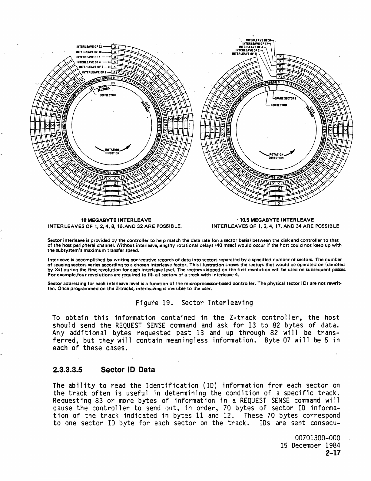
10
INTERLEAVES
MEGABVTE
OF
1,2,4,8,
INTERLEAVE
16,AND
32 ARE POSSIBLE.
·10.5
INTERLEAVES
'AOTATION~
DIRECTION
MEGABYTE
OF
1,2,4,
INTERLEAVE
17, AND 34 ARE POSSIBLE
Sector interleave
of
the
host peripheral channel. Without interleave.lengthy rotational delays (40 msec) would occur
the
subsystem's maximum transfer speed.
Interleave
of
spacing sectors varies according
by
Xs·)
during the first revolution for each interleave level. The sectors skipped on the first revolution
For
example-four revolutions are
Sector addressing for each interleave
ten.
Once programmed on
To
obtain
shoul
Any
ferred,
each
2.3.3.3.5
The
the
Requesting
cause
tion
to
one
is
provided by the controller
is
accomplished by writing consecutive records of data into sectors separated by a specified number of sectors. The number
this
d·
send
the
additional
but
they
of
these
to
a chosen interleave factor. This illustration shows the sectors that would be operated on (denoted
~equired
the
level
Z-tracks, interleaving
information
REQUEST
bytes
will
cases.
to
help match the data rate
to
fill
all
sectors of a track with interleave 4.
is
a function of the microprocessor-based controller. The physical sector
is
Figure
invisible
19.
to
the user.
Sector
contained
SENSE
requested
contain
command
past
meaningless
(on
a sector basis) between the disk and controller
Interleaving
in
the
and ask
13 and
information.
Z-track
for
up
Sector I D Data
abilit.y
track
the
of
to
often
83
controller
the
track
sector
read
is
or
10
the
useful
more
bytes
to
indicated
byte
for
Identification
in
determining
of
information
send
out,
in
each
in
bytes
sector
(10)
the
order,
11
and
on
the
information
condition
in a REQUEST
70
12.
track.
13
through
bytes
These
if
the host could not keep up with
will
be used on subsequent passes.
IDs
are not rewrit-
controller,
to
82
bytes
82
will
Byte
07
from each
the
of
be
will
sector
of a specific
of
IDs
SENSE
sector
70
are
bytes
sent
command
10
informa-
correspond
consecu-
to
host
data.
trans-
be 5
track.
will
that
in
on
00701300-000
15
December 1984
2-17
Page 45

t1ve'ly"
been
field
contain a
this
."
The
the
SENSE
through
data,
contain
's'ta~ti'ng'
flagged, the
of a sector
code
'at:' sector'
10
byte for'
is
not readable, the byte representing
that
specifies
'0,'
if 0 is
that
the
sector wi'll contain
error.
fdun"d
purpose are:
··-:·80::.~·.·.ID·.
81
=
82 = Out
83
= Sector
sector
EXTENDED
command,
and
75
R~·ad·'Er~~~·.(~i·th·er:
10
PES
Error
out of
and
limits).
of
Sync
the hardware apparently
Mark
10 bytes will
SENSE
all bytes
12
wi
11
contai n the
current track
in
all
cases.
(10
(the
Error
be
format.
number
read
after
TO
~
Sync'o'r
err~r
controller
(no
sector
sent
If
84
back
to
number
EXTENDED
bytes
accompanied
has
is
mark
to the host in bytes
98
SENSE,
as
on
that
track. ,
FO
..
(hex).
that
The
10'
.eRG)
missed
out of
was
error
codes
used
~.:-...
by
a position
two
sector
sync
with the
detected).
13
bytes are requested
82
will
be
error
meaningless. Bytes 0
cl ass
and
previously described.
If
·'a
sector
If
the
sector
(in
error
m~rks
10
hex)
signal
in
disk).
through
by
the
82
REQUEST
code, Z-track
Byte
07
h'as'
will
for
a
row
will
10
of
RETURNED
00
01
02
03
04
05
~t
07
08
Of
10
11
;-
------------------~
PARAMETERS
7
6
ADVA~==-
- -
________
---
ADVALI_~
~ST'WRITU
I
~~N'i.~'!.~·
1=015"81.£
=
,
T-
-RESER~;;;-
--
-=-
£cc---r
_N'.~._
1=C115"8~
__
- - - -
RESERVED
5
CLASS7
- -
_LOGICAL
-;;ROR'CLASS
I
INTERLEAVE
_.
LOGICAL
LOGICAL BLOCK
LOGICAL BLOCK
ADDITIONAL
-;R~TRA'CK~ER
4
3
=--I_-=-
.
RESERVED
--,-.-
---1-
________
BLOCK
ADDRESS
MSB
ADDRESS
ADDRESS
BLOCK
ADDRESS
L~
SENSE
LENGTH
~
I-
11.2.4
.••
ts.
OR
- _ I DWELL TIMER
CURRENT
TRACK
32
FOR
NUMBER
~
10
MSI
LSI
z o
__
cOOEo
___
-
--SENSE
--
(5)
MOYTE;
t.2.
- - - - -
;;;-
- - - -
ERROR
CODe
4.17.
0 R
34
FOR
COUNT
(2·12
--=--=
- -
=~_--=
t
OR
15)
--
_
--
L5
MOVTEI
-=-=--=
--
2.3.3.3.6
To
get a 1
host shoul d
data.
also
after
As
add
byte
Flagged Track Listing
isting
send
of the tracks
the
REQUEST
a response, the
the flagged track
98
will
be
meaningless. (Byte 0 =
00701300-000
15
December
1984
2-18
that
SENSE
controller
list
in bytes
have
been
command
will
send
83
fl
and
agged
ask
on a cartridge,
for
99
to
sense bytes 0 through
through 98.
first
byte.)
Any
the
255
bytes of
83
and
bytes requested
Page 46

· . . .
Byte
Byte
Byte
By~e,
Th
is
pattern is' repeated three
in bytes
83 = MSB
84 = LSB
85 = MSB
86"
,:::
L.S~,~.f..
87
through 98.
bytes corresponding
and'84) will
be
FO
of
Bad
of
Bad
of Track
Trac~
to
the
hex.
Byte
Track
Track
307
397..,
If
a'
bad
07
(the
first
,
more
times for spare' tracks 308, 309,
spare track
track
will
number
be
spare track)
has
not
for
that
91
in
all
been
assigned, the
spare
(e.g.,
of these cases.
and
bytes
310
two
83
2.3.3.4
The
FORMAT
tive
areas
specific
unique versions of the
The
8 inch removable disk subsystem allows multiple configurations of these
bits.
performed.
The
extended implementation
(bits
occur
result
Format Unit Command
COMMAND
BIT
BYTE
00
05
7
o
LOGICAL
-----r----------------
RESERVED
RESERV
UNIT
command
on
the disk. This standard
6
UNIT
implementation
command.
If
0,
1,
when
in
bit 4 is
In
and
bits
an
ILLEGAL
zero, the proposed
this
case, the values of
3 are disregarded). A device-specific
1,
2,
and
REQUEST
4 3 2
o
NUMBER
o o o o
FMT
DATA
COMP
RESERVED
RESERVED
INTERLEAVE
permits the host to
by
using byte
01
bits
SCSI
is
performed
4 are
set.
Any
error.
LST
DEFECT
set
parameters
SCSI
command
a through 4
LST
LIST
FMT
LINK
and
flag defec-
allows for device-
to
specify
standard implementation will
bits
if
a through 3 are. disregarded.
bit 4 is
one
and
bit 2 is
interpretation
other values for these
bits
vendor
be
zero
will
will
2.3.3
..
4.1
The
FORMAT
The
interleave
the
Z-tracks of the disk
for
a description of
fault
to
matting with
on
the disk
Standard Implementation
UNIT
command
value
an
interleave
verification
cartridge
is
executed
in
byte
04
cartridge
interleave).
of one. This
and
an
and
rearranges sector
off-line
will
be
(see Figure
A value of zero
bit
(see subsection
used
to
set
19
the
and
in
2.3.3.2).
interleave
paragraph
this
field
configuration indicates
value
2.3.3.3.4
will de-
media
auto-flaqqing operation of defective areas
IDs
physically
on
the disk.
00701300-000
15
December
on
for-
No
1984
2-19
Page 47

p.re,{i
This' process
ous.1y:
wri
tte.n
..
use,r
take~
betw~~n··l.~
condition' of the medla.
block .
.:
d,ata'
No
can
be:,
r,e.cov:e~e.d.
and
5"miriute~
parameter· bytes are sent
~fter
.thi s command
to complete,
after
begin.s
dependi.n~
the
command
on
•...
the"
data
. 2.3.3.4.2
This
command
status
off-line
of the
The
host
the
number
sib
1 e
dress.
of
no
..
Extended Implementation
will
has
been
condition.)
command.
must
of additional bytes to
by
four,
The
number
defects
be
executed
transferred.
The
defect
send
at
least
as
each four bytes'
must
be
in the range of 0 through 128, allowing a
and a maximum
off-line;
no
(See section
list
is
transferred
four bytes of data, the fo.urth byte indicating
be
transferred.
'wi
11
represent
of
32
defects reported.
will contain the logical block address .(most
defect.
this
been
The
first
device.
Ending
transferred.
ADDITIONAL
------~------------------------
BIT
BYTE
00
01
02
03
two
bytes of
status
The
defect
Format
COMMAND PARAMETERS
7
6
will
Unit Defect
5 4
each
list
DEFECT
defect address will
be
issued
must
as
be
in ascending order.
Media
RESERVED
RESERVED
RESERVED
LIST
LENGTH: N BYTES
action will begin
2.3.3.2
for
description of the
during the data phase
This
number
one
defec~.i
Each
four byte entry
Significant byte
always
soon
as
the complete
List
2
until'
must
ye
first)
be
o
ending
be
divi-
block
minimum
of a
zero for
list
ad-
has
00
01
oz
03
The
defect
The
list
fects
value then will
value
default
media
list
of defects will
may
be
flagged during
be
on
the Z-tracks of the
to
an
interleave
minutes, depending
in the defect
list.
00701300-000
15
December
1984
2-20
REPEAT
N/4
TIMES
MSB
LOGICAL
LSB
LOGICAL
must
be
in ascending order.
be
f1aqqed
verification)
specified in byte
cartridge.
of one. This process will take
on
the condition of the
WITHIN
THE
RESERVED
RESERVED
BLOCK
BLOCK
and
04
DEfINED
LENGTH:
ADDRESS
ADDRESS
the
media
and
of the
verified
reformatted.
command
to
A value of zero in
media
and
the
(additional de-
The
interleave
set
the
interleave
this
between
number
byte will
1.5
of
and
5
entries
Page 48

:th'e'
·c()nt·r·oll~'r.
complete;
QUEST
error
will
.,.t.her.e
,,..avai
SENSE
occurs duri
be
returned.
..
are
".no
1 abl.e',:
·'wiii"·:be·:iri'·.'
no
additional-commands
may
be
..
the
ng
spares
,ppe.rat,'i
used
"~'"
to
defect
If
media formatting
,t.he
o~··"~.i..J.l
the
determi
fl
:
ctr.q.c~,
"'H'ard\tiare:
will
ne
aggi ng,
Wi
J 1
abqrt
•.
...
".
'B'lisy
be
the
the
requires
b~_f1.~gge9,
. .
state
accepted
success
b 1
o~k
•
untir"'the'Operat:ion'"
•.
After
of
the
number
,flagging
.'
.....
..If
.',
the
operat
of
of
no.,
sp.ar~
',.'
process,
i on.
the 1 ast
a
sector
....
t.r..acks.
If
defect
..
. .
..
;:s
RE~
an
and
are.
, ,
2.3.3.4.3
Setting
COB
will
to
the
are
transferred
s;
x bytes
Bits
pl ace.
cated
3 through 7
by
subsystem
ADDITIONAL
-------------------------
BYTE
00
01
02
03
04
05
Device-specific Implementation'
bits
be
ignored,
1,
is:
~T
FORMAT
---C--I--I--I--r---------
Z.~C~
---------------------------'
Starting
the
first
cuted each time
the
first
an
ILLEGAL
set
REQUEST
2,
and 4 of
and
to
control
durinq
COMMAND PARAMETERS
7 6 4 3 2 1 0
of
at
the
bit
will
the
FLAG
SECTO!..
DEFINITION
DEFINITION
IlEFINITION
DEFINITION
byte
bit
7,
bit
it
command
be
error
byte
the
host must send
five
data
FLAG
_T~K_
DEPENDS
DEPENDS
DEPENDS
DEPENDS
00
specify
the
finds
is
sent,
ignored.
will
be
01
means
vari
ations
phase
UNFLAG
T~C~
ON
OPERATION
ON
OPERATION
ON
OPERATION
ON
OPERATION
RESERVED
of
Z.TRACKS
SPECIFIED
SPECIFIED
SPECIFIED
SPECIFIED
which
controller
set
high. Only
so
any
If
none
indicated
that
the
REMAKE
of
will
by
the
six
additional
of
this
command.
__
IN
BYTE
00
IN
BYTE
00
IN
BYTE
00
IN
BYTE
00
the
five
perform
one
bits
of
in byte
the
the
interleave
command.
The
~S~E~
operations
the
operation
00
first
five
controller.
parameter bytes
format
___
operation
to
bits
of
the
These bytes
for
the
'
is
to take
indi-
will
the
bits
be
right
is
exeset,
of
Definitions
eration
operations
of
the
other
being performed. These
follow.
Format Z-Track,
The
FORMAT
information
If
the
not spin
the
drive
Z-TRACK
on
Z-tracks
up
and
(including
been implemented
these
stay
conditions.
spinning
regardless
bytes in
this
definitions
Remake
the
become
Z-Track
operation
Z-tracks
unreadable
is
(see
continue spinning,
FORMAT
to
provide a
This
Z-TRACK).
operation
of the
six
byte extension depend
and
used
to
subsection
for
any
and
no
The
fai
lsafe
will
prior
cause the disk
contents
descriptions
change
the
2.3.3.3
reason,
operations
REMAKE
means
Z-TRACK
of
and
on
the
of the
five
cartridge-specific
and
Figure 18).
the,
cartridge
will
be
allowed
operation
data
condition
recovery under
to
spin
of
up
the
00701300-000
15
December
op-
new
will
on
has
and
Z-
1984
2-21
Page 49

,tracks.
cord;
.
For
ng . to
these
command
'.
The·:
controller
spec i
__
-----------------WARNING------------------~
REMAKE
tracks •
tw·o··
fi
ed
Z-
TRACK
The
opera'tion's~
·thenwfll·.
par:-ameters. .
unf1
ags
user
is
responsible for
.
the····
'sfx:
att.~mptto
all
previously
b"y'te'
extenslc)ri'
r.ewri.te·
d~ta
trye
..
f1
agged
integrity.
of
·the·
~~~track$
·FORMAT.
..
9.C~·
UNIT
follows
The
six
ADDITIONAL
BIT
BYTE
00
01
02
03
COMMAND
1
FORMAT
--tt--f-
Z.TRACKS
",ST·WRITK
~!'.fN'i't.t<iK
I-OISAB&.K
-=--_--=-__=_
PARAMETERS
6
_0
_
ECC
O-KNABLK
I-OISABLE
RESERVED
5
_0
_
INTERLEAVE
_
--
1
~-.
-----------_._------------------
04
os
__
----------------WARNING------------------~
If
the cartridge
ECC,
ALL
stroyed.
FURTHERMORE:
enabled will
if
~CC
was
byte
extension
customer data
already enabled.
for
is
non-ECC
The
REMAKE
ALWAYS
this
destroy
case
4
_0
_
11.2.4.8.1&.
RESERVED
RESERVED
RESERVED
on
the cartridge will
3 2
.
REMAKE
--
Z.TRACKS
L
OR
r=
and
Z-TRACK
all
C
.
32
FOR10
MBYTE:
DWELL
is
comnand
customer data,
TIMER
to
is:
--------
__
~E~VED
1.2.4.11.
COUNT
be
changed
OR
34
(2·12
FOR
OR
___
10.5
15)
be
with
even
o
_
MBYlE)
.-==
to
de-
ECC
ADDITIONAL
BIT
BYTE
00
01
02
03
04
os
•
FLAG
Flag
The
rep
Sector,
FLAG
1 acement of defect·;
00701300-000
15
December
2-22
COMMAND
· 1
---------
SECTOR
SECTOR
1984
RESERVED
ONL
Y
Flag Track
PARAMETERS
6
A
•
SECTOTA.
and
FLAG
5
TRACf
LOGICAL
LSB
LOGICAL
RESERVED
TRACK
ve
4 3 2 o
•
=:J.
--------------
BLOCK
ADDRESS
BLOCK
operations
areas.
on
•
MSB
LOGICAL
ADDRESS
the
::::I_-=-
BLOCK
ADDRESS
provide a
d;
sk.
In
RESERVEO
means
each
::-
case,
~
::.
for
logical
the
bad
Page 50

areas' are rep
data block will
place.
The
,.-aced····\-iith
automatfc~lly
host
is
data bytes are not
maintenance of data
.and/Qr
,
.us~.r
...
~
________________
;spare's'~'an'd
..
any'
'fur"fher"
reference the spare block' assigned in
not required to
moved
integrity
from
the defective block-to the spare,
under these operations is
WAANING
keep
a defective block
__________________ _
accesses "lo'
up
the·fl
agged'
its
table.
so
Th~
the
to the host
Since data bytes are not
'ation,
the
host
integrity.
ouri
ng a FLAG
sector
10
copied .into the sector
field
SECTOR
operat i on, a
of the defective
10
maining unflagged sector
over
responsible for
this
tion
track,
pletion
no
track should
The
(bit/1=1 in ending
gedc
set,
for
special
AD
be
byte
track
ror
operation should take
tai
one
sector' position to allow
moving
track physically following the flaqged
takes
or
pl
ace.
an
10
c.annot
in the ending
If
be
status
other spare sectors are
be
flagged.
REQUEST
SENSE
command
status)
If
the
error
was
due
the logical block address returned should
the
FLAG
error
VALID
sent
04
should
as
did not occur
SECTOR
class
bit
is not
as
the address for the
be
command.
and
set
set
indicating
the logical block address to
and
the
pl
n.
transferred
is
responsible for maintaining
hex
FO
sector,
field
IDs
of the next unflagged
through the
room
for
the data for the flagged
no
other spare sectors are avai 1 able
wri
tten,
byte
·av
ai 1 ab
should
the
(bit
1 e (vi
be
issued
comnand
1=1). After
aa
to determine the disk location to
to a
code
If
media
the
problem
error
are returned
in
this
pattern
and
the original sector
is
oper-
wri
sector.
end
of the track are
this
operation.
sector,
sector,
after
returns
verification
REQUEST
after
and
occurred
(10
Hex).
every
the
be
SENSE
AD
sent
on
In
data
tten
The
and
this
an
abnormal
conmand),
check
VALID
as
an
ECC
this
into the
10
The
all
moved
host
sectors
opera-
on
condition
be
flag-
bit
the address
sector, a
case, the
but the logical block address returned should
FLAG
that
AD
VALID
ace
since the exact
SECTOR
it
be
bit
is
command.
is
the
flagged.
not
set,
error
Al
so,
'bit
ECC
sector
If
an
no
on
ECC
sector
sector flagging
location is uncer-
7
the
is
re-
is
on
that
comthat
the
was
of
same
er-
For
FLAG
written
part
TRACK
on
of the
the Z-tracks. This information
startup
spare tracks are avai 1 able
updated for
controller.
some
The
track being spared .
. Unflag Tracks
Issuing
an
UNFLAG
will unflag all flagged tracks
be
will
-----
written in the Z-track locations, thus clearing the
----
-------
--------------------
operations, the defective track
is
sequence each time a
on
the ·cartridge or the Z-tracks cannot
reason,
an
error
condition will
cartridge
logical block address given
TRACKs
operation
on
as
part of the
the
cartridge.
list
read
may
for a cartridge
by
the
controller
is
inserted.
be
reported
fall
anywhere
FORMAT
An
UNIT
FOFO
hex
bad
00701300-000
.
15
December
is
as
If
no
be
by
the
on
the
command
pattern
track
1984
2-23
Page 51

table.···
.host
tension
..
Sin~e··
is.
responsible
to
'the
data·
format
byt-es.are·.
for
maintaining
unit
command
not
..
·.transferred
data
'for
integrity.
this
i·n.
thls·
operation
operation,
The
sfx
is:
byte
..
'ex:"
the
2.3.3.5
ADDITIONAL
BIT
BYTE
~
_______ L ________
01
02
03
04
05
COMMAND
7
..
..
'
<~r'7I"
PARAMETERS
&
5
~I'UNruGT--;~'-'-'
RESERVED
RESERVED
RESERVED
RESERVED
RESERVED
Format Track Command
COMMAND
BIT
BYTE
00
01
02
03
04
05
7
o
VU
8
LUN
4
!~~_I
5
o
4
o
LOGICAL
LSB
LOGICAL
3
____ l _____________
3
BLOCK
ADDRESS
BLOCK
ADDRESS
RESERVED
MS8
2
2
LBA
-.
'RES'ERV;;-'-'
o
-'-'.-.
LINK
'.-.
_
o
o
The
FORMAT
matting
rather
quenced,
sequenc.e
than
the
identified
spared.
of
this
Recovery
command
2.3.3.6
COMMAND
BYTE
00
04
05
00701300-000
15
December 1984
2-24
TRACK
defects.
with
track
command
similar
the
entire
checked
If'
of
user
allows
to
for
no
spare
data
the
the
FORMAT
media.
medi a
for
sectors
this
begins.
Reassign Blocks Command
BIT
7
a
VU
&
LUN
5
o o
host
to
initiate
UNIT
The
defects,
track
4 3 2
RESERVED
RESERVED
RESERVED
conmand,
track's
are
available,
is
and
not
sector
sectors
possible
RESERVED
a media
but
on
IDs
the
checking/for-
a
track
will
spared
.track
once
be
for
will
execution
o
LINK
basis
rese-
any
be
Page 52

The
REASSIGN
. affect:ing
SECTOR
fect
media
2.3.3.4.2
·th~·.:
command,
list
for a description
assigned using
:
:NOTE':-
'.
Therefore,
BLOCKS
integri
command
allows
ty··af. any :other.· ·b·lack
which
does
a'lter
is' sent during'
of
other
the
this
the
host
blocks
data
'phase of the'
list).
spares.
l:he····
ab; 1
ity'~
of' ·:the. ·subsystem·'to··
blo'c~
....
;:s
......
ba·s··ed.'·:on'
two
logical
:'''fragg';ng~
blocks
each block address passed in
the
higher .logical block also
the
1
dresses
the
address
.address
09i cal block
of
a physical
controller
is
is
al
an
an
odd
so
will
even
numbered
will
numbered
wi
11
be
reass
sector
not reaSSign twice.
to
spare media
s·.
·on.·
tl1e;
dev.i
ce·
on
the
same
command
The
~
':a:"
will
the
be
specified
"512"
:byt'e:'
be
reaSSigned
defect
block,
reassigned. If.
blocks
reass
ign.-' a .'.
"'secto'r;~'"
list.
the
block, ·the next lower
i qned.
are in
the
If
both ad-
defer.t
list,
defects
(un 1 ike"·;
track).
without
the·.
The
(see subsection
will
be
'.
for
If
next
FLAG,
de-'
re-
2.3.3.7
The
READ
to
the
COB;
and
2.3.3.8
Read Data Command
COMMAND
liT
IYTE
00
05
DATA
host.
the
__
7
LOGICAL
YU
command
The
number
---------------------WARNING------------------
If
byte
&
UNIT
NUMBER
initiates
starting
of
blocks
04
is
Write Data Command
COMMAND
BIT
BYTE
00
01
7 &
o
LOGICAL
UNIT
block
0,
NUMBER
5
o
LOGICAL
LSB
LOGICAL
NUMBER
to
then
o
LOGICAL
4
o
BLOCK
ADDRESS
BLOCK
OF
BLOCKS
a
transfer
is
specified
be
transferred
256
blocks are
4
o
BLOCK
ADDRESS
3
MSB
ADDRESS
2
LOGICAL
IL~CK
of
data
by
bytes 01, 02,
is
transferred.
1 z
MSI
LOGICAL
BLOCK
o
ADDRESS
LINK
from
the
disk subsystem
and
given in byte 04.
__
o
o
ADDRESS
03
of
the
05
YU
LSI
LOGICAL
NUMBER
OF
BLOCK
BLOCKS
ADDRESS
LINK
00701300-000
15
December
1984
2-25
Page 53

The·,
'disk
and
by
byte 04.
WRITE.·
subsy'stem~
03
of
DATA
the
COB,
command i ni
'.
'The
startfng'
and
r----------WARNING---------w
,If
,byte
04
,the
is
t.i
ates"a
number
0,
then
,transfer.
of.
'data
,'from,
bi6ck address -'{s' specified
of the blocks to
256
blocks.are
be
transferred
transferred~
the,
'by
bytes'at,.
host. to the
'02'~
is
given
2.3.3.9
The
SEEK
Seek Command
COMMAND
BIT
BYTE
00
01
~---;----------
02
03
04
05
command
7
o
LOGICAL
VU
requests the indicated drive
8
UNIT
NUMBER
5
o
LOGICAL
LSB
LOGICAL
RESERVED.
4
o
----------------
BLOCK
ADDRESS
BLOCK
3 2 o
MSB
LOGICAL
ADDRESS
ing the specified logical block address. This
the
REZERO
UNIT
command.
(See subsection
2.3.3.2.)
2.3.3.10 Inquiry Command
BLOCK
ADDRESS
LINK
to
seek to the track contain-
is
an
off-line
command,
like
COMMAND
o
LINK
The
tion
BIT
BYTE
00
01
02
03
04
05
INQUIRY
vu
command
6
LUN
requests the
to the host. This can.
5
o
be
NUMBER
used
4 3
RESERVED
RESERVED
OF
BYTES
REQUESTED
controller
to
z
RESERVED
send
device-specific
to allow device-independent software to
adapt dynamically to the available hardware. Although only the
returned parameter bytes
transfer
of-
zero
the
is
number
given.
of bytes requested, but will return
currently
have
any
meaning, the
controller
no
bytes
00701300-000
15
December
1984
2-26
informa-
first
if
a count
six
will
Page 54

RETURNED PARAMETERS
aiT
BYTE
"'-'j-'
' .
.00
....
.-.:.
01
-
0%
-
~
04
;:-
...:.
--
------_._-.-.
.
'--.--
-------------------------
--------------------------
1-
';;;;R;;;
__
--
-L
------------------------------
&
..
-
TR;;;VED',
__
5
---~.-
0
______
t-10.0-r;:;II:;;-E;;;;;E~I~;;.;T.;;;r
..Lt):o1D.:L~~E~E~II~S~U~__
ADDITIONAL
4
-" -.....
DEVICE·TYPE.CODE
...
~-' . ....:..;:..~----------
DEVICE
TYPE
SCSI
REVISION
~ESERV~
ADDITIONAL
UNIT
3
-
.. ~-..
(DOt
QUALIFIER
LEVEL
(00)
____
LENGTH N BYTES
PARAMETER
%
-.~~.---
.
------
-'-I-;-
BYTES
__
o
.. -..
.
IRESER-;;';-
_
__
-.
Device type
80
(hex) for a removable device without user assigned codes. Revision level
is
currently
05. Byte
unit
board
2.3~3.11
parameter byte contains the
as
code
04
indicated above.
NOTE:
the
The
that
A
on
Start/Stop Command
COMMAND
BIT
BYTE
00
01-
t - -
is
00
for a
00
for
unspecified. Zeroes will
contains a count of the additional bytes requested.
Th
is
command
UNIT
controller
;s
00
will
the
0
ATTENTION
'not loaded
be
controller.
6
LUN
direct
cannot
returned in byte
access device. Device
current
does not check
status,
distinguish
and
a drive
4
be
switch
for,
nor does
between
that
00
for
RESERVED
returned in
settings
nor
it
cl
;s
not
any
LUN
% o
-r-------- -----------
~
03_1
04
05
-----------~~~----------
_________
t-
~E~D
RESERVED
_______
Qualifier
any
on
report,
ear
it.
a drive
present.
queried
_
FLAG
REQ
bytes
the
IMM
--
'-START
O-STOP
LINK
The
code
digital
is
after
first
The
START/STOP
specified
fied
will spin
cal
will
REMOVAL
drive will spin
and a cartridqe
keep
drive
down.
flashinq
command
command
be
The
with a
allows the host to request
spun
and
up
or
downo
up.
drive cannot
loaded.
If
bit 0 of
The
the bezel
STOP
command.
If
bit
byte
be
spun
drive will spin
is
still
0 of byte
04
is
up
if
the load lever
locked
that
zero, the specified drive
down,
when
the spindle of the
04
;s
one, the speci-
is
not
but the green
using a
PREVENT
00701300-000
15
December
verti-
light
MEDIA
1984
2-27
Page 55

As
with
spin
this
will
zero,
.
.If._
up
command
be
the
bi,t
.1.
·-·;-s·.zero,-·'
loading. a 'cartridge,:the
the
drive.
on-1
executed
command
of.
byte
dwelf
seeks are. 'enabled"., . .
~
________________
For
in·e
or off-1
off-line,
will
.05
be
.i.s
this
reason,
ine.
freeing
executed
one,. dwell seeks., are
"controller'
the
host
If
bit 0 ·of
the
SCSI
on-line
WARNING
(and
__________________
may·
require
is
given
byte
bus.
If
also
,91sa~led
'several-seconds
t~e
01'
is
bit
tie
up
.. , ,I.f
choice of doing
one, the·
0
of
the
SCSI
.bit 7 of
byte
,byte
command
01
bus) •
".
_
-
.to
is
05
-'
The purpose
life.-
By
of
the
disabling
dwell seeks
dwell
shortened.
2.3.3.12 Send Diagno.stic Command
COMMAND
The
SEND
routines
will
go
sued as
Any
other
BIT'
BYTE
00
05
DIAGNOSTIC
described
off-line
·shown;
configurations
7 &
o
VU
Command
in
until
the
other
5 4
o
LUN
allows
subsection
the
diaqnostics
SCS I opt
will
generate
DATA
DATA
the
3.3
ions
is
to
extend media
seeks,
RESERVED
VARIABLE
VARIABLE
host
on
the
media
3 2
LENGTH
MSB
LENGTH
LSB
to
specified
life
invoke
are completed. Byte
for
th
i s
command
an
Illegal
Request
the
LUN.
may
be
o
o
o
startup
are·
o
LINK
diagnostic
,The
02
must
controller
not supported.
error.
be
is-
2.3.3.13
The
PREVENT/ALLOW
of
the
or
packing
controller
Prevent/Allow Media Removal Command
COMMAND
BIT
BYTE
00
os
cartridge
the
not
00701300-000
15
December
2-28
to
1984
7 &
o
VU
MEDIA
at
an
files
poll
LUN
REMOVAL
undesirable
on
the
device.
the
bezel switch
o
command
4 3
RESERVED
RESERVED
RESERVED
allows
time, such as
This
command
on
the
specified
2 o
o
RESERVED
FLAG
REQ
the
host to prevent removal
when
updating a
works
by
drive.
LINK
instructing
The
directory
the
command
Page 56

wi
11
remain
power-on
If
bit 0 of
byte
04
reset
is
zero,
in
-'effect
occ~rs.
byte
04
media
'unti
is
one,
removal
T .
eX'pl
media
i"ci
will
tTy'
enabled'~'"
removal
be
enabled.
will
'or'
'lint
be
inhibited.
i'f'
a··;·.ho's·t·'reset-
If
bit 0 of
"'or';
2.3.3.14
The
ten byte
and
.b1ock
transfer
08
is
00,
If
byte
the
last
The
block-
(an
SCSI
returned
Read
COMMAND
BIT
BYTE
00
09
size
wi
11
the
08
Capacity Command
7
o
VU
READ
CAPACITY
of a unit
encounter a substant;
address
is
one,
logical block
size
option),
by
this
for
an
command
8
LUN
5
command
and
also to determine track boundaries,
and
this
this
size
command
on
the
device
of the
same
Invalid Request
is
as
follows.
4
o
LOGICAL
BLOCK
LOGICAL
BLOCK
LOGICAL
BLOCK
LOGICAL
BLOCK
RESERVED
RESERVED
PARTIAL/FULL
3 2
AODRESS
ADDRESS
ADDRESS
ADDRESS
MEDIA
INDIe.
RESERVED
MSB
LSI
allows the host to determine the
al
de 1 ay
last
will report the address
physical track
;s
always
error
for a seek to occur.
block
on
the drive
and
as
on
the specified block.
256.
will
If
bit a of
be
issued.
o
LINK
capacity'
where
If
is
reported.
block size of
byte
The
01
is
data format
data
byte
set
RETURNED PARAMETERS
BIT
BYTE
,--
00
01
02
03
04
05
06
07
-------------------
8
4
LOGICAL
LOGICAL
LOGICAL
LOGICAL
BLOCK
BLOCK
BLOCK
BLOCK
BLOCK
ADDRESS
BLOCK
BLOCK
BLOCK
ADDRESS
SIZE
MSI • ALWAYS
SIZE·
ALWAYS
SIZE·
ALWAYS
SIZE
LSB·
3 z
MSB
ADDRESS
ADDRESS
LSI
0
0
1
ALWAYS
0
o
00701300-000
15
December
1984
2-29
Page 57

2.3~3.15
. :-Extended
COMMAND
BIT
BYTE
Read·
7
Command
6
5
4
3 2
o
00
..--
·01
..
02
03
04
07
08
09
The
EXTENDED
provides for
256
biocks. This
starting
block address
block count
data
is
bytes are
set
(an
SCSI
o
._'--
--------
-------------------------
VU
READ
larger
is
gi
transferred,
option),
'LUN ;
command
operates the
capacity devices
command
ven
in bytes
initiates
is
specified
and
an
Ill~gal
-_-....._-------_.
LOGICAL
LOGICAL
LOGICAL
LOGICAL
NUMBER
NUMBER
07
and
no
o
BLOCK
BLOCK
BLOCK
BLOCK
RESERVED
OF
BLOCKS
OF
BLOCKS
same
and
also permits requests for
a
transfer
in
08.
error
Request
.
RESERVED
ADDRESS
ADDRESS
ADDRESS
ADDRESS
MSB
LSB
COB
If
is
reported.
error
MSB
LSB
as
the
o
READ
DATA
o
LINK
command,
more
of data to the
bytes
02
through
host.
OS,
and
zero blocks are requested,
If
will
be
issued.
bit 0 of
byte
but
than
The
the
no
01
2.3.3.16
The
EXTENDED
Extended Write Command
COMMAND
BIT
BYTE
00
08
09
WRITE
but provides for
than
256
blocks. This
7
o
VU
command
larger
6
5
LOGICAL
LOGICAL
LOGICAL
LOGICAL
NUMBER
NUMBER
operates the
capacity devices
command
initiates
4
o
BLOCK
BLOCK
BLOCK
BLOCK
RESERVED
OF
OF
ADDRESS
ADDRESS
ADDRESS
ADDRESS
BLOCKS
BLOCKS
same
and
a
3
RESERVED
MSB
LSB
as
2 o
MSB
LSB
•
does
the
RELATIVE
WRITE
o
ADDRESS
LINK
DATA
also permits requests for
transfer
of data
from
command,
more
the host.
00701300-000
15
December
1984
2-30
Page 58

,The
..
star.t.tng:
b16ck
data
is
count
bytes
set
·2.3.3.1-7
(an
SCSI
COMMAND
BIT
BYTE
;·b.l
ock ····address··
is
given in
are
transferred,
option),
7
bytes
8
an
·i·s.·
..
specified'
07
and
no·
Illegal
and
Off.
error
Request
4
in·
the'
CDB····bytes·
If
zero blocks are
is
reported.
error
3
will
2
If
be
:02.'-05';'
requested,.
bit
a
issued.
'and···the·
of
'byte
0
no
01
00
01
02
0 0 0
-------------_._--------
os
06
07
08
09
The
WRITE
AND
mand, but provides,
fer
of
data
bytes
zero
02
through
blocks are
reported.
quest
error
VERIFY
from
If
bits
will
VU
requested,
be
LUN
command
post-write
the
host.
05,
and
0
or 1 of
issued.
operates
CRC
The
the
block count
no
data
byte
RESERVED
-------------
LOGICAL
BLOCK
ADDRESS
LOGICAL
BLOCK
ADDRESS
LOGICAL
BLOCK
ADDRESS
LOGICAL
BLOCK
ADDRESS
RESERVED
NUMBER
OF
BlOCKS
MSB
NUMBER
OF
BLOCKS
LSB
the
same
checking. This
starting
bytes
01
block address
is
gi
are
is
set
(SCSI
MSB
LSB
as does
command
ven
in bytes
transferred,
option~),
the
WRITE
initiates
is
specified
07
and
----
RELATIVE
ADDRESS
----
LINK
and
no
an
Illegal
DATA
a
transin
08.
error
com-
COB.
If
is
Re-
2.3.3
..
18
The
READ
a
CRC
Read Long Command
COMMAND
BIT
BYTE
00
01
02
03
04
05
LONG
error
7
VU
command
is
encountered.
6
LUN
functions
4 3 2
o
LOGICAL
LOGICAL
BLOCK
NUMBER
identically
If a CRC
BlOCK
ADDRESS
OF
BLOCKS
error
LOGICAL
BLOCK
ADDRESS
LSB
to
the
occurs using
ADDRESS
READ
MSB
DATA
the
15
o
LINK
command,
standard
00701300-000
December
unless
READ
1984
2-31
Page 59

,DATA,
be
Using
then ending
countered,
The
"ror
,
'comm·and.
command~
'u'sed'
if
this
the' ho'st'
command~
status
the
host
occurs~.
is
responsible
this.
the
data
,w.i.ll not,
is
if
an
will
command
com~and.,w-.ill,
will
2.4 POWER INTERFACE
be
returned
'to,
the
capab'l'e of determinatin'g't'he
error'
be
sent with the check
for
occurs, the ,data will
be
aborted
correction
fU,nct.jon-
after
or
integrity
..t,hes,arne
bit
sending
.~.s..,does,
host.,
Thi s ,command
usefulness"of'
be
passed to the
set.
of
If
an
the
suspect data block.
the
data.
~he
,usuaJ
'can
'the"
data.'
host,
error
If
is
no
ener-
·READ:,DAT.A.
Power
in Table
watts
the
Table 1
the
have
maximum
amps
supply
(single
drive
lists
different
1.
in a
current
The
drive
rapid
the
operating
instantaneous
drive
for
approximately 4 sec
requirement.
requirements
subsystem has a
and
random
Single Drive
+5
±.5%
Ripple
+12
±.5% '
Ripple
maximum
peak
(10 msec) are requi red
the
sidered in
selection
controller).
seek
mode.
MAXIMUM
with
Controller
1.5 amps (avg)
mv RMS
30
1.5 amps
mv RMS
60
1.5 amps peak 1.8 amps (avg)
120
(avg)
3 amps
25%
300
current
modes
of
requirements of
In
particular,
from
for
a seek. These
of subsystem
for
the
drive
maximum
continuous
This
maximum
Values are
TABLE
POWER
mv
duty
mv
1
REQUIREMENTS
p.p
p.p
30
2.0 amps
cycl.e
60 mv RMS 300
requirements
the
drive.
sufficient
the
+12
vdc
power
and
controller
power
can
shown
Two
Drives
with
Controller
1.8 amps
120
mv
3.5 amps
mv
each supply voltage
that
mv
One
RMS
(avg)
from
Note
duration
disk spin-up
supply. Also
peak
requi rements
supplies.
are
detailed
consumption of
be
achieved only with
in Table 1.
pea
k
p.p
pea
k
P-P
certain
requires
to
up
must
specify
to
operations
up
1.4
be
to
25
for
the
1.S
amps
con-
Active seeking or
time. Because of
drives,
than
for
power
the
requirements
initial
track
this
system.
following
and
00701300-000
15
December
1984
2-32
can
because
for
each additional
take
one
pl
ace only
controller
drive
on
one
drive
board can control
are
significantly
at a
two
less
Page 60

"·3.0
OPERATIONAL ·INFORMATION
This 'manual'
subsystem.
the
drive
,·,Contro 1 s
,
..
switch·;··:·a:·mQtor·.';loading·.';lever·~,;·
along with
face,
this
3.1
power
sectioD.
CARTRIDGE
Proper use
vatio~
of
moval
3.1.1
The
time
of
the
manual
procedures.
cartridge
the
cartridge
the
front
improper
Bernoulli
access
to
section
Cartridge
contains
loading, handling,
are explained.
for.operating
the
cables
supply,
and
care
data
integrity
deals
Loading and Removal
may
motor load
containing
of
the
cartridqe
plate
the
will
disk.
..
the
subsystem
and
connectors needed
and
the
USE
of
the
subsystem
and
with
be
lever
dri
cartridge
inserted
is
the
access door should face toward
ve
(see
insertion.
~nteract
fnf6rmation~needed
write
i.nclude.·a~cartr.idg~,··remova
·and:··.·t.wo···.I.:.ED.~:tndi:c·ators:~·~··~
controller
to
drive
cartridge
assurance of long
loading,
into
parallel
Fi
gure
with
As
the
to
20).
the
and
drive,
the
Interlocks
cartridge
open
to
ope'rate
protection,
for
the
host-to-subsystem
interface
are importdnt
cartridge
handling,
access door
drive
opening.
is
the
access door, thus providing
the
disk
and
removal
1 push
..
These·:·:tomponents';'"
are described in
for
the
life.
write
the
in
the
inserted,
This
protect,
end
first,
The
edge
stop button
system prevent
keys
storage'
from
..
button
inter-
preser-
portion
and
re-
any
of
the
on
on
the
...
Once
load
loaded
blink.
drive
To
gin
the
to
and
If a command
BUSY
recei
down,
error
for
the
cartridge
the
motor
the
motor,
At
this
motor reaches
remove
to
green
unload
the
the
bl
ink
LED
the
cartridge
status
ved
by
an
error
speci
the
fi
user.to
and
cartridge,
as
turns
motor.
requiring a drive
will
the
ed
minute (depending
a
command
motor
by
comes
locking
up
to
host.
is
in pl ace,
initi
the
time a
ate
green
latch
operating
push
the
motor
off
and
At
this
removed.
be
reported
subsystem
st
atus
wi
11
in response
remove
upon
the
system
the
speed,
the
drive
LED
on
pin
speed
the'
stop
spins
the
down.
latch
time
to
spin
and
the
from
be
reported
the
to a request
cartridge.
activity),
load
of
lever
course,
load
spinup.
the
will
the
engage
green
button.
When
pin
the
lever
up
drive
host
After
and
BUSY
lever
front
may
When
of
the
to
LED
will
The
the
motor has
will
or
wi
sense
may
down
will
direct
th
Cartri
disengage
be
is
spin up.
1 y
command.
a time delay of
the
spun
spinning
down
the
status
be
turned clockwise
the
lock
green
·lever
dri
the"
glow
has completely
ve
wi
11
leverQ
steadily.
LED
then will be-
come
to
to a stop,
allow the
begi n
As
lever
turned counterclockwise
received
from
the
host,
If a corrmand
after
dge
wi
11
a dr i
Not
drive
drive
be
ve
has spun
Loaded
Thi
s allows time
10
seconds to 1
will
respond
motoro
reported
as
As
to
00701300-000
15
December
to
to
the
is
the
to
the
the
1984
3-1
Page 61
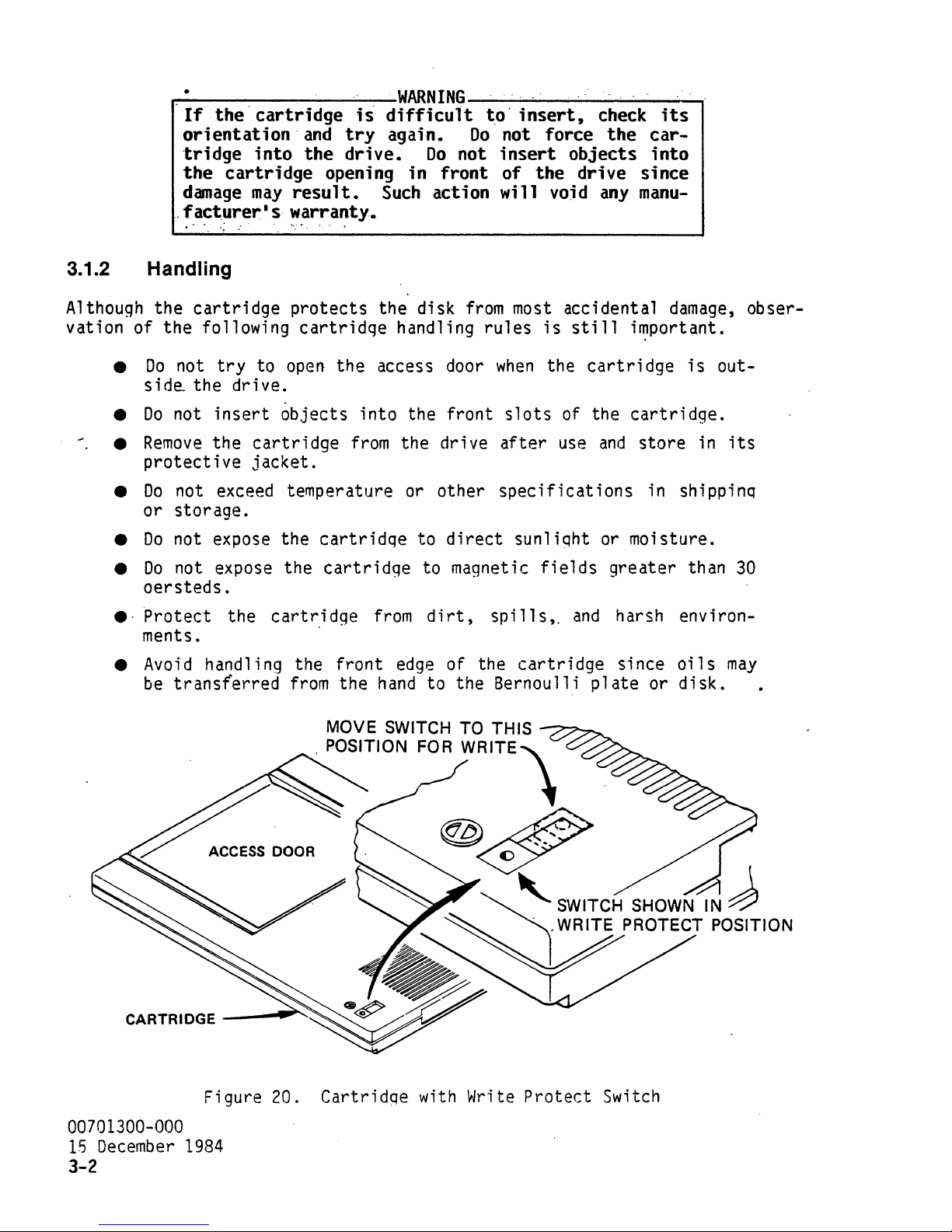
~--------~--~---WARNING----~--~--~--~~
If
the·
cartridge
orientation·
tridge
the
damage
.facturer1s
...
into
cartridge
may
. ;
:'
and
the
result.
warranty
.......
is
try
drive.
opening
Such
•
.
difficult
again.
Do
in
front
action
t.o·
00 not
not
insert
will
insert,
of
force
objects
the
drive
void any
check
the
manu-
its
car-
into
since
3.1.2
Although the
vation of
Handling
the
•
Do
side.. the
•
Do
not
•
Remove
protective
•
Do
not exceed temperature or other
or
storage.
•
Do
not expose the
•
Do
not expose the
oersteds
•
·Protect
ments. .
•
Avoid
be
transterred
cartridge
following
not
try
to
drive.
insert
the
cartridge
jacket.
.
the
handling the
protects
cartridge
open
objects
cartridge
the access door
cartridqe
cartridge
front
from
the
the disk
into
from
from
hand
from
handling
the
the drive
to
to magnetic
dirt,
edge
to the Bernoulli
rules
when
front
direct
spills,.
of the
slots
after
specifications
most
sunliqht or moisture.
accidental
is
still
the
cartridge
of the
use
fields
and
cartridge
plate
damage,
i~portant.
is
cartridge.
and
store
in shippinq
greater
harsh environ-
since
or
in
than
oils
disk.
obser-
out-
its
30
may
CARTRIDGE
00701300-000
15
December
3-2
MOVE SWITCH TO THIS
. POSITION FOR
WRITE"\
@#
-_
Figure 20. Cartridqe with Write
1984
................
~---.
~
~
SWITCH SHOWN
1 WRITE PROTECT POSITION
Protect
Switch
~
J
Page 62

3.1.3..
The
picteq
closest
time the
3.2 OPERATOR CONTROLS
The
a motor load
ors are located
..
Write .protect.- " .
write
protect
in Figure 20.
to
the
edge
cartridge
ope~ator
interface
lever,
on
switch
of the
is
is'
The
cartridge
cartridge
out of the
of the subsystem
and
two
LED
the
front
located
drive.
indicators.
of the
on
'.one
corner"--of the
is
write protected
as
shown.
is
made
The
drive~
The
switch
up
of a
switch,
cartridge
when
may
push
button switch,
lever,
as
the switch
be
moved
and
indicat-
de~
"
is
any
3.2.1
A
push
tridge.
eration-
pin
to
unload the motor. ' .
3.2.2 Load Lever
The
from
clock'wise,
ed, a switch
At
this
Stop Button
buttori switch
Pushinq the button
and
stop the. spindle motor.
that
locks the load lever will disenqaqe
load lever
being
removed
it
allows. the motor to load.'
is
time a latch pin
is
used
t~
stop the disk
signals
is
used-
to load the
while the
motor
closed to signal the
is
engaged,
the
controller
Once
motor
is
spinning.
When
controller
which
and
allow
to
the
motor
and
the lever will
and
also to prevent the cartridg'e
As
the
motor
that
removal
finish
has
stopped, the latch
of the car-
the present op-
the lever
is
completely
the
,motor
prevents the load lever
ing turned counterclockwise (and unloading the motor) while the
spinning.
the
cartridge
tridge
3.2.3 Indicators
from
The
is
being
lever
fuJly
removed
is
constructed to
inserted into the
until
the motor
interfere
drive,
has
and
been
with the
cartridge
also to prevent the
unloaded.
become
is
rotated
is
loaded.
from
motor
unless
free
seat-
be-
is
car-
The
green
tridge
LED
is
inserted
on
the front of the drive
will begin blinking to
the
mot~r
to
signify
ed
period, a dwell timeout
at
half
ition
motor
spins
lever
The
red
speed
speed.
from
is
at
down
to
allow the
LED
that
half
either
and
will
is
at the operating point the green
the drive
The
to
full
full
then turns
cartridge
glow
and
the load lever
signify
is
ready.
may
green
[ED
speed.
or
half
off
to
whenever
is
the
READY
is
rotated clockwise, the green
that
occur,
the
motor
If
the drive
which
is
coming
is
causes the drive
will blink momentarily
If
the stop button
speed, the green
as
the latch pin disengages
be
unloaded.
the drive
is
actively
is
LED
indicator.
up
~o
LED
not
will
used
glbw
for
motor
as
it
makes
pushed
while the drive
will blink
from
servicing a
15
When a car-
speed.
When
steadily
an
extend-
to spin
the
trans-
as
the
motor
the load
command
.
00701300-000
December
.
1984
LED
3-3
Page 63

3.3"
.....
ST
.,
__
-----------WARNING'---------~-----_
Do
not
,
green
result.
ARTU,P
.
attempt
LED
is
DIAGNOSTICS
:'..
to
turn
glowing,
..
'
the
since
load
mechanical
1 ever,
whi
binding
1 e
the
will'
Upon
RAM
system
and
ROM
powerup
and
wi
11
the i
nterf
ace
contro
11
er
wi
veri fy proper buffer operat ion.
proximately 3 seconds. After completion, control
mal
operating firmware
If
a
failure
occurs during these
will not respond to a
on
the diagnostic display.
01
02
03
If a more
the read channel
these
tests.
ROM
CRC
--
RAM
test
--
Interface
extensive self-check
and
The
user data untouched.
second
test
host via the
mately
dent
10
tests.
1.
if
switch 3
SEND
additional seconds to complete
.
Seek
Test
to
begin execution of
initial
test
select,
failure
and
the following
failure
(buffer)
read/write
.test
is
desired, additional diagnostics
capability
failure
read/write diagnostics
The
diagnostics will
on
SI
is
in
the
DIAGNOSTIC
--
Check
command.
various seek
commands
tests,
of the drive
use
areas
be
invoked
ON
position
These
and
perform the following indepen-
profiles
11
perform a self-check
Thi s test
is
turned over to the nor-
from
the
error
on
the host.
controller
cJdes
can
may
be
the Z-tracks, leaving
following the
or
upon
request
takes
interface
be
reported
that
check
appended
normal
from
diagnostics take approxi-
and
directions.
on
ap-
to
3
the
2.
CRC
Check
3.
Overrun
4. Data Sync/ID
5.
If
code
an
6.
7.
error
will
Data
Data
ECC
Pattern
Pattern
Check
occurs
be
written to the diagnostic display.
of a diagnostic
next
error
REQUEST
command
(bit
SENSE
will
1 hfgh).
command.
because of the
teed.
00701300-000
15
December
1984
3-4
--
Check
in
failure
be
aborted, with completion
failure
Verify proper
--
Verify proper overrun detection.
Sync
Check
--
CRC
error
Verify
detection.
that
data
detected.
Read
Write Tests
Verify proper
Tests
--
Read
from
--
ECC
any
of these diagnostic
when
it
attempts to issue the next
and
compare
the Z-tracks.
Write various
Z-tracks.
write
Read
and
tests,
status
The
specific
Subsequent
of diagnostic
error
code
commands
tests,
wi
the
11
and
ID
sync
various data patterns
test
and
read
patterns
compare.
capability.
the corresponding
The
host will
indicating
can
be
determined
be
accepted
results
cannot
errors
be
informed
command
..
an
execution
vi
norma
11
be
are
to the
error
This
a the
y, but
guaran-
Page 64

ADDRESS SELECT JUMPE
J3.
DISPLAY CONNECTOR
DIAGNOSTIC
HOST INTERFACE CABLE
J1CONNECTOR
JP~6
.
PIN 1
--H--~-AI/
ACTUATOR/SOLENOID CABLE
J8 CONNECTOR
J7 CONNECTOR
MOTOR CABLE
Figure 21. Printed
3.4.2 Drive Interface Cable
The
drive
the drive(
pin connector.
troller
plugging locations
interface
s).
to the
cable connects the
Each
last
sucessive drive
The
maximum
drive
34
and
43.
is
Circuit
Board
;s
recommended
1.0 m (3.3
~~~ffi:l-~:::::-)J1
J6 CONNECTOR
DRIVE INTERFACE CABLE
1
IN
and
Main
controller
attached to the
length of
ft.).
Cable
Locations
to the
same
this
The
cable
connectors are
interface
CONNECTOR
HEAD CABLE
board
cable
from
the conkeyed
of
by a 50
by
3.4.3 Power Cable
Power
connected to a
grounds should
to the subsystem should
common
be
ground
connected to a
possible. This wire should
mended
ft.)
power
exceed
grounding
or
less
applied,
0.06
scheme.
to minimize
dc
voltage
volts.
Where
line
00701300-000
15
December
1984
3-6
be
at the
be
at
possible cable lengths should
drop.
between
distributed
power
good
least
supply (Figure 23).
earth ground, using
14
Recommended
any
two
radially
with
gage. Figure
wire
grounds
size
in
the system should not
all
as
short a wire
24
shows
be
is
16
return wires
Power
supply
as
the
recom-
1.0 m (3.3
gage;
With
Page 65

.r---------.
----.---.
-------l.
[.
I
I
'I'·
l
\
i
./
\
I
L~~:~),
~
I
L.:./
,/"
'"
. I • . . .
~
'.
. .
50
CONDUCTOR,
y"
HOST
.
POWER
COLORED
INTERFACE
914~(3&
.
CABLE
EDGE
CABLE
IN.)
~~~+12VDC
~
~
(not
supplied
8M
(20
(not
FTl
MAX
. . -I
~n
supplied
with
with
drivel
drivel
_____
~.
-\
.
GROUNDI
~+5VDC
I
I
I
'I
I
1
i
I
1 I
I
I -
~/
90~
.\.
201_
I
I
. I
I .
I
L
__
!oPTIONAL
'
\
I
I
I
L_,
_____________________
·_.
__ . ________________
SERVICE
TOOL
.'.
TO
ERROR
ON
LSI
BOARD
DRIVE
(not
ERROR
PORT
DIGITAL
INTERFACE
supplied
READOUT
with
.
CABLE
drive)
- -
HEX
DISPLAYS
ASSEMBLY
INI
§~~§§~~=~~~§~
~
COLORED
EDGE
4
CONNECTOR
(supplied
--
PIN
.
~
\ '
with
drivel
- - -
1
-----~.~
. I
--
--
-l
~
J
I
I
I,
I
.
Figure 22. Cabling
and
Connector Requirements
00701300-000
15
December
1984
3-7
Page 66

SW1
SW2
SW3 SW4
OFF OFF
OFF
ON OFF
ON
SW5
OFF =
OFF = PARITY CHECKING
.
ON
ON
ON = REPEATING STARTUP DIAGNOSTICS
OFF = 10.0 CODE ENABLED
ON
MANUAL
(MUST
.. ~ .NQ·PARITYCHECKING
='
RETRIES ENABLED WITHOUT STARTUP DIAGNOSTICS
==
RETRIES DISABLED WITHOUT STARTUP DIAGNOSTICS
POWER-ON
BE
SWITCHED OFF
RESET
FOR
SUBSYSTEM TO OPERATE)
= RETRIES ENABLED WITH STARTUP DIAGNOSTICS
= 10.5
CODE
ENAB LED
o
o
o
DRlVE
o
POWER
DIAGNOSTIC
INTERFACE CONNECTOR J2
CONNECTOR
. PIN 1
CONNECTOR
o
+5VDC
J4
~
D
JP16
ADDRESS
SELECT
JUMPER • ADDRESS e
RN2
+5 VDC RETURN
VDC RETURN
+12
+12VDC
OPTION
HOST
INTERFACE
CONNECTOR
.
J1
TERMINATORS
SWITCHES
PIN 1
PI
N 1
--+;::;:::==3n:l}5;:-j
J8
PIN1-~m~
J7
L-
____________
(Actuator cables
Figure 23.
Digital
00701300-000
'15
December
1984
·3-8
PI
N 1
PIN 1
~~~========~~
ahd
jumpers
Controller
--f::ca~Eirl
r.=::::T!1:=:=----I-J3
..1'":
:~:
:r"T'I:
:1"'1"'1:
:~:
:~:
:;;;:
:~:
:~:
;:;: : ;:;: : ;;:::
Pii:
:1~O;d
J6
identified
Terminations
in Figure
and
~--PIN1
J2 }
DRIVE
LECT
PE
11/1
RS
SE
J4 J U M
21)
Address Options
Page 67

POWER
SUPPLIES
+5VDC
,.
GND
.'
..
'"
"
~
+12
VDC
POWER SUPPLY GROUND
POWER SUPPLY
.
GROUND
HOST
ELECTRONICS
,
ELECTRONICS,
"
DRIVE'1
. '
GND
MINIMUM
EARTH
GROUND
GROUNDING I NSTRUCTIONS
KEEP GROUND WIRES AS
•
TIE
ALL
POWER SUPPLY GROUNDS
• CONNECT THE POWER SUPPLY GROUND
COMMON
• POWER
POWER SOURCE'
EARTH
TO
MORE
GROUND USING
THAN
NOT
ANOTHER
Figure 24.
LENGTH
SHORT
ONE
CONTROLLER
____________________________
AS POSSIBLE.
TO
A COMMON
MINIMUM
CONTROLLER.
Recommended
POINT
AND
THE
CHASSIS GROUNDS TO A GOOD
LENGTH WIRE.
SHOULD COME
Grounding
AT
THE
DIRECTLY
ELECTRONICS
DRIVE
POWER SUPPLY.
2
FROM
_
3.4.4 Diagnostic Error Display Port
A four pin
8
bit
error
Use
of
interface
If
an
shift
register
diagnostic tool for
format)
error
code
this
port at the diagnostic connector provides the user with
corresponding to the
port
is
especially
helpful in
development. Pin-out of the port
Pin
error
is
No.
1
2
3
4
is
discovered,
IC
is
available
necessary to receive the
use
with the port to display
from
Output
Ground
Clock
+5
vdc
Seri
al
Data
it
is
clocked
the manufacturer.
i nformat ion.
hex
error
codes
identifying
is
as
serially
bits
Appendix
listed
problems during
follows.
to the display
for display.
error
information
B includes ordering
15
in
Appendix
port.
An
optional
(in
00701300-000
December
an
A.
A
hex
1984
3-9
Page 68

"3.4.5"
.'
Drive Addressing:
Three
nector
selection.
between
...
t~~.
The
row~
of
on
the drive
The
the upper
10w~r.
dri
.~t1d
...
ves
can
midQ.l¢.,r,ow.s
seven pins,
interface
seven position
and
middle
be
addressed in
each
.of.
located
just
above
board (Figure 23), control the drtve address
jumper
rows
:pi.n.s..·
..
any
of pins,
block
and
order but
selects
drive 1
no
dress.
3.4.6 Controller Addressing and Option Selection
The
eight position
the
controller
operation.
during device
The
selection.
shunt in place, indicating
sele~tion
Dip
switch
sequence (subsystem address).
S1·
These switches are
with
Bus
If
power
already
termination
more
than
one
provided at the
either
end,
resistor
bus
address shunt
board (Figure
shunt
bank
Only
is
used
to enable or disable various options (Figure 23).
sampled
on
may
not
is
provided
device
two
is
physical
pacs
RN1,
JP16
24)
must
allows user
one
out of the eight positions should
which
address
and
be
set
definition
line
only following a
have
by
any
resistor
effect.
pacs
connected to the
ends
of the bus.
RN2,
and
RN3
five position
up
correctly
must
power-on
RN1,
SCSI
should
the drive interface cbn-
drive 0
two
can
of the
be
reset.
RN2,
if
have
prior
controller
asserted during the
and
if
installed
the
DIP
switch
to subsystem
Changing.
RN3
(Figure 23).
installed
same'
bus, termination should
If
the
controller
be
removed.
is
between
ad-
S1
on
address
have
them
be
not at
a
00701300-000
15
December
3-10
1984
Page 69

·
..
4.0. CONTROLLER ,OPTIONS
..
·
Subsystem
and
arbitration.
tration
The
subsystem supports
post-~rite
tions'invo1ve
Post-write
This veri-fication ensures
host
a
still
command
next track (whichever
written
this
be
The
operation
substantia.1 for multiple single sector
error
recovery
track,
the data
fective
head
some
for reading (unless
additional
track during a write operation
phase
hardware options are available for 'error correction
A description of the
is
now
in preparation.
two
levels
CRC
CRC
has
has
on
the
correction
if
a read operation
plus
all
from
sector
checking
some
overhead
causes the subsystem to
the data available, in case
been
completed, or
track during
is
one
the other sectors
the defective
and
flag
ti.me.
and
error
that
that
the user should
the write operation
whenever
comes
first),
this
additional revolution, or
code
hardware option
fails.
sector.
it
if
necessary.)
it
is
needed
for writes.
when
is
described.
ECC
follows; information
of
error
correction
correcti.on hardware options:
code
be
verify
the drive
command
data
any
retries
the
transfer
verifies
are readable.
40
transfers
is
a sophisticated system for data
A special, sector
on
the
same
(The
track,
host should then rewrite the de-
The
ECC
to recover data) but
The
following steps take place for
ECC
is
selected.
co"des
on
the
(ECC)
'.
Both
aware
on
was
of.
the disk
successful while the
of these op-
after
are required. After
must
that
continue
all
the sectors
The
overhead for
msec. This overhead
on
the
same
(ECC
are
system involves
Overhead
track.
sector)
used
it
does
on
to
recreate
no
require
for each
(ECC)
arbi-
write.
on
the
can
each
over-
each
1.
All
sectors
that
are to
use in constructing the
2.
Overhead
be'
not
this
Each
--
be
wri
phase
sector
One
revolution
tten.
is
eliminated.
is
wri
If
tten
Step 1 for constructing the
. 3.
Overhead
The
ECC
--
Same
as
sector· for
for
thi
s track or
sector.
Overhead
--
No
additional overhead.
4. Sectors written are checked
Overhead
tors,
--
One
revolution
including the
ECC
be
written during
ECC
sector.
is
needed
all
sectors
as
received'
ECC
sector.
normal
write operation .
for
CRC
is
required to
sector.
to read
on
the track are to
and
command
validity.
this
a1
so
is
verify
command
all
sectors
added
written
all updated sec-
are read for
be
to those
after
00701300-000
15
December
that
wri
tten,
from
the 1
1984
are
ast
4-1
Page 70

.
The'.
total
transfers.
4.2 ARBITRATION
..
Inf.ormati9n
.
vi
d
e'd
at
relative
on
,.
at
.. th.is
e r ,rat
a
·overhead· of·
§uq,s.ystern.,opt,i,OD
e.
':':
t~e':
"
ECC
'option depends·
,i~',
..
nqw,..i'1·preparati,on·'·'and
..
.
upon:
,the ,s';ze
'w;ll~'be"pro~"
of
the'
00701300-000
15
December
4-2
1984
Page 71

The
prior
following
to
disk
1.
Provide
interconnections
drive
operation.
an
interface
to
must
the
be
ho.st
made
•.
after
- .
subsystem unpacking and'
'2. Connect
drives.
3.
Supply
The
controller
system.
face
its
ion.
are
subsystem
The
the
interface
board must
test;
factory,
instal1eq.
fill
Orderi
each
illustrate
_ Connect;-qn
cable
drive(s)
All ·necessary
included in
host ;
cables
ng
of
the
general requirements.
ng
i nformat ion
of
the
the
"contro11er"
power
is
to
the
by a 50
via
the
nterf
cable
ace
to
be
custom
may
be
removed
both the
subsystem normally
Each
cables
the
tables
to
resident
to
the
controller
conductor
data
the
drive
controller
.'
and
power
be supplied
dri
ve
of
these
is
is
presented
and
and
the
subsystem.
within
host
and
control
interface
by
fit
for
from
and
cables
presented in
describe
the
is
(Figure
drive
a four conductor
cab 1 es are
particular
by
the
drive
contro
will
may
in-
its'
resident
first
made
21).
interfac~
signals
the
11
er
be
be
Append
this
their
drive
th.rough a
The
and
cable.
supp
1 i
system
user; however, since the
to
make
as
a subsystem takes
shipped with a
ordered
i x
B.
subsection.
application.
drive
of a
50
controller
cable in a
power
Power
cable.
ed
by
configurations~
the
from
Det
ai 1
to
any
one
or
two
conductor host
is
connected
daisy
for
the
second
is
supplied
the
user,
connection
drive
the
ed
Figures
wh i ch
p1
interface
manufacturer
i nformat i
21
additional
drive
chain
The
controller
and
ace at
through
inter-
to
allows
on
sub- .
fashdrive
drive
since
cable
about
'.
to
the
the
to
24
3
..
4.1
The
n a 1
s,
2.0
commended
mended
Host
host
commands,
of
this
if
~
_________________
The
host interface' cable
cable both contain
connector.
Danage
nected properly.
product
products
other types
the
Interface Cable
interface
manual
length
it
is
is
not campatible with
of
of
subsysten.
connection
and
dat a between
includes a
of
this
to
be
used
the
drives
cable
outside
WARNING
__________________
and
50
conductors
may
occur
The
drive
interface
manufacturer,
to
this
is a 50
the
description
is
6 m
pin cable
host
of the
(20
a shielded
the drive
and
if
they are not
interface
use the
cable
that
and
of
any
connection
connector will
and
the
ft).
enclosure.
that
interface.
A shielded cable
LSI
carries
contra
same
con-'
on
this
previous
of
damage
11
The
15
__
all
the
sig-
er.
00701300-000
December
Sect i
maximum
is
recom-
1984
re-
3-5
on
Page 72

APPENDIX A
DIAGNOSTIC PORT ERROR CODES .
FOR
10/10.5 MEGABYTE, 8 INCH DISK STORAGE SUBSYTEM
WITH
EXTENDED SCSI
THE
00701300-000
15
December
1984
A-I
Page 73

:,'INTRODUCTION'
Error i nformat i
provided
in
equivalent
~:F'irst:~'·'-~r~or".code's'>
tic
disp'lay board
the
Diagnostic
Second,
mand.
and
specific
given
Key
than
Sense
an
class.
for
by
Keys
error
In
this
error
portion
each
location
on
for
the
this
proposed
Appendix as subsystem Diagnostic
SCSI
ar'e
'.tlocked'::ser1'aTly'
(see
Port
subsectfon
Error
codes are
case,
code.
In
error.
the
The
of
the
addition,
The
in
the
error
device.
are included in
10/10.5
error
av
error
codes (Table
Code,
ai 1
ab
is
1 e
is
cla$s
the
SCSI
Sense
Key
subsystem.
the
proposed
megaby:te
8 inch di
A-I).
fo :a:"'shfft"fegl$ter':'oii:,the
l.3.4).
a one-byte hexadecimal
as
defined
groups
The
code
EXTENDED
groups
This' type
a response
by
~pecifying
together
indicates a particul
'SENSE
errors
Definitions
ANSI
standard,
Interface.
Note
ges a check
zeroes,
Error
power-ups
closed
command
again
th
at,
Code
the
for
accord i
condition
which
will
and
subsystem
since
the
ng
to
the
proposed
must
would
indicate
indicate
every time
reports
the
media might have been changed.
operation
be
reported.
no
error,
the
medi
a changed
the
load
a check
to,~ake
place~
SCS I st
lever
condition
but
The
the
status.
on
and
SCSI
Sense
the
to
sk
Port
'of
to
the
the
format
together
of
the
ard
s,
class
Key
This
drive
the
The
'storage subsystem' 1 s
Error
error
Codes
'code,
(2
digit)
REQUEST
both
errors
an
related
ar
reports
by
type,
error
and
''d~i
ag'nos':"
known
number.
SENSE
error
error
a Sense
rather
cl
asses
their
'as
com-
class
to
in a
and
Small Computer System
whenever
and
and
means
is
hos,t
command
med
i a
ch
an-
code values are
Diagnostic
that
opened
after
must
on
and
the
be
Port
all
then
next
sent
a
One
roes:
class
was
other
the
and
error
INVALID
code
changed.
report
REQUEST
bits
exists
signify
in which
error.
that
no
Do
error
the
not
error
assume,
class
that
has occurred, nor
and
code are both ze-
zeroes in
the
that
the
error
media
00701300-000
15
December
1984
A-2
Page 74

.OIA~NOS.TIC.·
The
diagnostic
tive
ture
for the 10/10.5 megabyte, 8 inch disk storage drive subsystem. Struc-
of the
~ORT.:
ERROR
error
error
code
..
COq~S·:
port
is
error
as
follows.
codes presented in
this
Appendix
are
effec-
E
= Error
=
Type
T
Error
_-----------',i
_--------~xecution
_-----------C,orrmand
_---------"A
sce·1-l
1
terat
arieou's
..
Parameter
i.ons
lEE E E
Description of the
lowing
listing.
Code
~Hex)
/
(
00
Miscellaneous
80
Type
NORMAL
=
(High
=
CARTRIDGE
on a cartridge
errors
and
Error
COMPLETION
Priority)
WR
ITE
that
their
--
No
error
possible
was
Errors
PROTECT --Caused
is
in the write protect
~auses
are included
detected.
by
tryi
ng
any
mode.
wri
in
te
the
fol-
operat i
on
82
83
84
86
89
*8A
=
CARTRIDGE
detect
=
HARDWARE/DISK
interrupt
may
not
=
CANNOT
hardware
NOT
if
the
generated
be
READ
is
information
=
SPIN
come
=
PARITY
ity
=
OVERRUN
empty
UP
FAIL --An
up
to
ERROR --Will
error
on
ON
or
fill
LOADED --Reported
cartridge
SYNC
ERROR --This
happening in
Z-TRACKS --An
;s
inserted
by
the format sequencer
sync
with the disk format.
indication
unable to read data
on
the Z-tracks
is
indication
speed within the
be
allotted
reported
the host bus.
RECORD
1
--
Record 1 interface
within six revolutions.
when
and
error
from
invalid.
that
the drive
time.
if
the
the
controller
the bezel closedo
is
an
indication
is
not
that
either
the
the Z-tracks or
motor
controller
buffer
has
detects a par-
either
15
is
unable to
that
happeni
the
ng
controller
that
the
failed to
failed to
00701300-000
December
1984
A-3
or
Page 75

*88
.::
OVERRUN
empty
or
ON
fill
'RECORD"
2
within
,~-,.
Record
six
revolutions.
2'·fnterface·
,.
buffer
eitner-fai
led to·
8e =
·'.··8·b:
..
··~
8F
=
.
90
=
91
=
92
=
93
=
94
=
MEDIA
cess
"'Etc
was
NO
h
ardw
tridge
hardware
Not
SERVO
Could be preceded
DRIVE
drive
FATAL
track.
RESEQUENCE
CHANGED --Cartridge
to
drive.
":WAS'~
OPTION --Tried
fN·vbK.~O;:.'~,;;:·
invoked
are opt
ECC
assigned.
LOOP
SELECTION
to
SEEK
to
ion.
turned on.
option,
ERROR --Failure
another.
ERROR --Retries
ERROR --Not
.
'last'"
recover
to
Can
but cannot
by
ERROR --Error
May
:,:11,0'
data.
invoke
al so occur
An
ECC
an
83
error.
be preceded
able
may
have been changed
.
,w"as"
':temp
leted"s'ucces~fu"ly'
'.
' ,
",
an
ECC
operation
when
cartridge
write
•
to
acquire
in switching se.rvo
by a 91
exhausted in
to
read a
try;
can
track
sector
without
ng
to
be
read without
on
drive
error.
trying
10
when
since 1 ast
but:ECC'
.
the
ECC/ARB
format a
selection.
__
J~oP
to
fr9111
seek
formatting.
target
ac-
car-
the
one
-.----.--
95
=
Execution
40
=
41
=
42
=
43
=
*Errors
reported
the
host's
ation.
10
to
Errors
SECTOR
sector
SEEK
after
OUT
sector
SECTOR
during
8A
and
to
transfer
No
data
READ
target
ERROR
track.
NOT
on
the
FAIL
four
OF
SYNC --The
marks during
MARK
an
10
88
may
the
host.
loss
~~
Failed
FOUND --Controller
disk.
--
Controller
tries.
ERROR --Contro
write
be
rate
will
~peration.
seen
Th
is
is
slow, can occur during
occur.
to
read 10
was
controller
the
operation.
11
occasionally
cond; t ion, though
was
unable
detected
er
was
in
on
source
unable
to
unab
the
most 1 ike
find
two
1 e
LED
any
track
to
the
consecutive missing
to
readout,
read or
before seeking
find
read a
the
requested
sector
yet not
1 y
to
occur
write
requested
track
mark
be
when
oper-
00701300-000
15
December
1984
A-4
Page 76
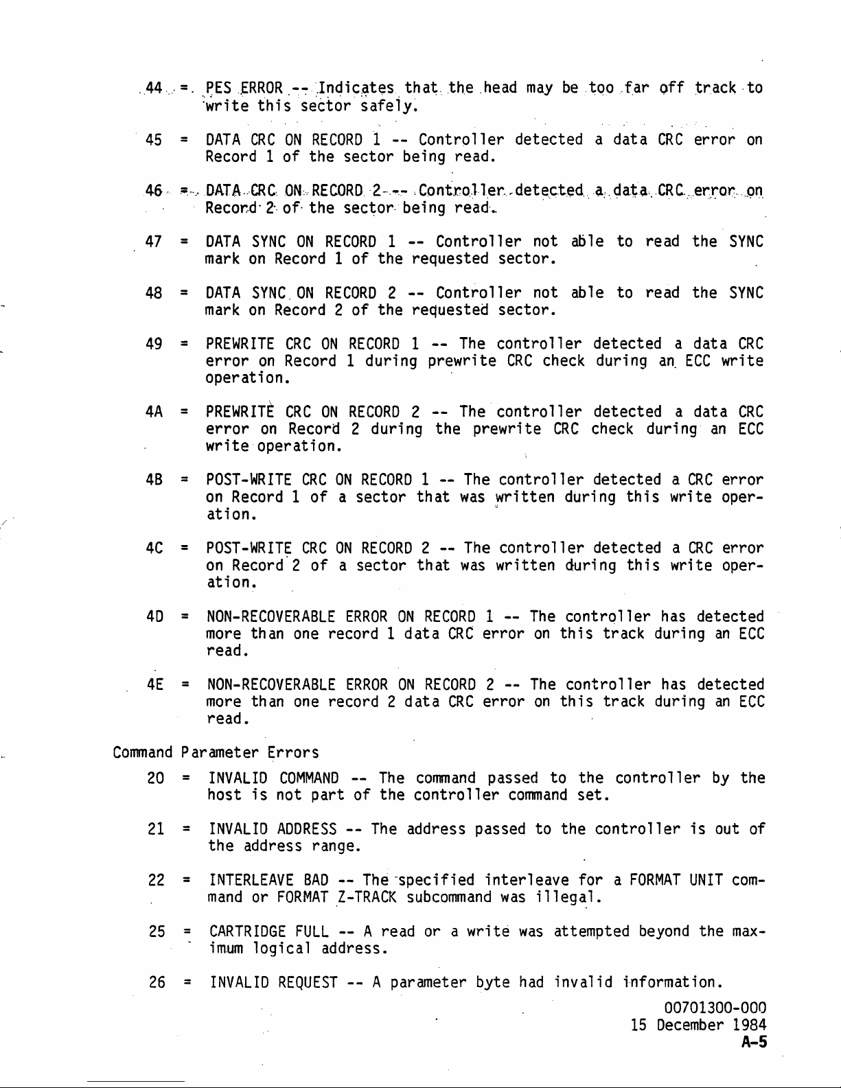
·.44
.
45
46··
47
48
49
4A
48
....
=.
~ES
..
ERROR
:~rit~
=
DATA
Record
.~,·.-DATA···CRC..
Recor..d·
=
DATA
mark
=
DATA
mark
=
PREWRITE
error
operati
=
PREWRITE
error
.-~Jndic.ates
thiss~t~6riafeiy~
CRC
ON
RECORD
1
--
tha~.
Controller detected a data
1 of the sector being read.
ON:·
..
2-,
of·
SYNC
on
Record
SYNC.
on
Record
CRC
on
Record
RECORD.
the
ON
RECORD
ON
RECORD 2 --
ON
·2~·.-.~
sec~or,
,Cont.ro.ll.er.~det~.c.t.ed
being
1
--
1 of the requested sector.
2 of the requested sector.
RECORD 1 --
1 duri
ng
prewri
on.
CRC
ON
RECORD 2 --
on
Record
2 duri
ng
write operation.
=
POST-WRITE
on
Record
CRC
ON
RECORD
1 of a sector
1
that
ation.
the
.head
read·
..
may
be
.~Qo.f.ar
...
·a:
..
~ata
...
off tr.ack ·to
CRC
error
CRC.:
..
e~ro~···.P~.
Controller not able to read the
Controller not able to read the
The
controller detected a data
te
CRC
The
controller
the prewri
--
The
controller detected a
was
written during
~
te
check
CRC
duri
n9
an,
ECC
detected a data
check
duri
ng
CRC
this
write oper-
SYNC
SYNC
wri
an
error
on
CRC
te
CRC
ECC
4C
=
40
=
4E
=
Command
Parameter Errors
20
=
21
=
22
=
25
=
POST-WRITE
on
Record'2 of a sector
ati
on.
CRC
ON
NON-RECOVERABLE
more
than
one
record 1 data
read.
NON-RECOVERABLE
more
than
one
record 2 data
read.
INVALID
host
INVALID
COMMAND --The
is
not part of the
ADDRESS --The
the address range.
INTERLEAVE
mand
or
CARTRIDGE
-
im.um
10gi
BAD --The
FORMAT
.Z-TRACK
FULL --A read or a write
ca
1 address.
RECORD 2 --
ERROR
ERROR
ON
ON
address passed to the
-specified interleave for a
subcommand
The
that
was
RECORD
CRe
1
error
RECORD 2 --
CRC
error
command
passed to the controller
controller
controller detected a
written during
--
The
controller
on
this
The
controller
on
this
command
set.
this
has
track during
has
track during
controller
FORMAT
was
il1eg~1.
was
attempted
beyond
CRC
error
write oper-
detected
an
ECC
detected
an
ECC
by
the
is
out of
UNIT
the
com-
max-
26
=
INVALID
REQUEST --A parameter byte
had
invalid information.
15
00701300-000
December
1984
A-5
Page 77

. Alteration· Errors: .
10
=
NO
11
.
,12
;
13
SPARE
=
NO
SPARE
....
,~
..
J~~RITE<
quested..'
=
BAD
TRACK
SECTOR
TRACK --No
..
ID
..
ERRqR
FORMAT' --Track
could not determine
14
=
RESEQUENCE
READ
write read pass
15
=
TOO
16
MANY
th
an
=
RESEQUENCE
FLAGGED
spare-s
quencing.
Startup Diagnostic Errors
-~.
:,~~.·
ERROR --An
prior
IDs
av
a; 1 ab
WRITE
No
remai
ni
ng
spare sectors are
remaining spare tracks are
...
CQ.t)tr.o
which
1 e.
ERROR --An
11er~
to
~esequencing.
--
Resequence
was.
,.
had
excessive
sector to
10
read error
10
error
un.ab)~
flag.
routine
on
the.
track.
on
the
cartridge
..
::tQ;.~·~ri.t~:,.
.an
:,10
...
as
.
re-
.
,
.
bad
IDs
..
Controller
was
found
was
detected
more
detected
on
IDs
after
a pre-
flagged·
rese-
FO = SEEK
Fl
=
CRC
error
F3 = WRITE
F4 = READ
F5 = ALL
ERROR --Missed
DETECTION
ERROR --Di
sectors.
BUFFER
BUFFER
ONES
FAIL· --Wrote
FAIL --Read
READ
ERROR --Had
sectors factory-written
F6 = STRESS
tors
F7 = INCREMENTING
READ
ERROR --Had
factory-written with a
READ
ERROR --Had
. sectors factory-written with
F8 = ALL
F9 = STRESS
ONES
not
match
match
COMPARE
the
al i ones
COMPARE
the
stress
ERROR --Had
ERROR--
data written at time of
one
of
20
random
d not detect
data
data
when
when
a data
wit~
an
all
a data error
stress
a data
an
incrementing data
a data
seeks.
all
the buffers
the buffers
error
ones
data
on
data pattern.
error
error
data written at time of
Had
a data
error
when
test.
of the prewrftten
on
were
were
all
empty.
full.
attempts to read
CRC
pattern.
all attempts to read sec-
on
all attempts to read
pattern.
when
the data read did
test.
the data read did not
FA = INCREMENTING
with
FB = ECC
FC = SYNC
is
an
incrementing data pattern.
CIRCUITRY
CIRCUITRY
not functioning properly.
COMPARE
ERROR --ECC
ERROR --Circuitry
00701300-000
15
December
1984
A-6
ERROR --Same
circuitry
to detect
as
stress
compare
error
not functioning properly.
10
'and
data
sync
only
marks
Page 78

TABLE
·ERROR
A~1
CODES'
'.
No.
. '00:::
80
82
83
84
86
89
8A
8B
8C
80
SF
40
41
42
43
44
45
46
47
48
49
4A
4B
4C
40
4E
4F**
20
21
22
25
26
Diagnostic Port
Error
Codes*·*
. Description
'NORMAL
"
CARTRIDGE WRITE PROTECTED
CARTRIDGE
HARDWARE/DISK SYNC ERROR
CANNOT READ· Z·
SPINUP
PARITY
OVERRUN
OVERRUN
MEDIA
'ECC WAS
NO OPTION
SECTOR NOT FOUND
SEEK
OUT OF SYNC
SECTOR
PES
DATA
DATA
DATA
RECORD 1
DATA
RECORD 2
PREWRITE
(ECC)
PREWRITE
(ECC)
POST·WRITE
(ECC)
POST·WRITE CRC
(ECC)
NONRECOVERABLE
RECORD 1
NONRECOVERABLE ERROR
RECORD 2 (ECC)
NONRECOVERABLE ERROR
ECC
INVALID
INVALID
INTERLEAVE
CARTRIDGE
INVALID
COMPLETION:
FAIL
ERROR
ON
ON
CHANGED
INVOKED
FAIL
MARK
ERROR
CRC
ON
CRC
ON
SYNC
SYNC
CRC
CRC
(ECC)
SECTOR
COMMAND
ADDRESS
REQUEST
NOT
LOADED
TRACK
RECORD 1
RECORD·2
ERROR
RECORD 1
RECORD 2
ON
ON
ON RECORD 1
ON RECORD 2
CRC
ON RECORD 1
ON
RECORD 2
ERROR
BAD
FULL
ON
ON
ON
Sense*
Class*
Key
. :
"'0: ' .
"0
1.
2
4
9
4
4
4
4
6
0
1
9 1
3
4
3 a 1
3
3
0
3
3
3 1
3 1
9
1
9 1
3
0 3
3
0 3
3 1
3
9 1
5 2
5
2 1
5 1
5
0 A
5
0
No.
0'"
1
0 9
0
0
0 4
2 3·
1
1
1
1 4
1 5
1
7
.1
6
B
B
0
8
C
2
3
1
1 1
1
1
3
3
C
C
1
1
0
0
A
.0
SCSI
Equivalent
Error
Codes
Description
NO'SENSE
WRITE PROTECTED
MEDIA
NO
NO
DRIVE
VENDOR UNIQUE
DATA
DATA
NO
CORRECTABLE
NO
RECORD NOT FOUND
SEEK
NO
10 ADDRESS
WRITE
UNCORRECTABLE
UNCORRECTABLE
DATA
DATA
VENDOR UNIQUE
VENDOR UNIQUE
WRITE
WRITE
UNCORRECTABLE
UNCORRECTABLE
VENDOR
INVALID
ILLEG
INTERLEAVE
INSUFFICIENT CAPACITY
NO
NOT
INDEX
TRACK
SENSE
ECC/ARB OPTION
INDEX
SENSE
LOADED
SIGNAL
0
NOT
READY
TRANSFER
TRANSFER
ERROR
SIGNAL
FAULT
ADDRESS
ADDRESS
FAULT
FAULT
UNIQUE
COMMAND
..
"L
BLOCK ADDRESS
NOT
NOT
DATA
MARK
MARK
MARK
ERROR
DATA
DATA
DATA
DATA
COMPLETE
COMPLETE
CHECK
NOT FOUND
NOT FOUND
NOT
ERROR
ERROR
FOUND
ERROR
ERROR
10
NO
11
12·16
01
02
03
91·95
FO·FC
*
See
"Could
***See Diagnostic Port Error
SPARE SECTOR
NO
SPARE
FLAG
ROM TEST FAI LURE
RAM TEST FAI LURE
INTERFACE BUFFER TEST
FAILURE
SYNCHRONIZATION ERROR
DIAGNOSTICS FAI LURE
ANSC X3T9.2 Proposed Standard, Small Computer System Interface.
be
anyone
TRACK
SECTOR FAI LURE
of
the following errors: 40, 44, 47, 48;
Codes
listing in this Appendix.
3·
3
9 1
·
·
·
9
A
0
0 A
·
·
·
O-C
3
4B
through 4E.
A
INSUFFICIENT CAPACITY
INSUFFICIENT CAPACITY
E
VENDOR UNIQUE
·
} SEE SUBSECTION 3.3.
·
·
C
TECHNICAL
MANUAL,
VENDOR UNIQUE
DIAGNOSTIC
Code
4F
is
DESCRIPTION
00701300
ERROR
not
actually
15
seen
on the
LEOs..
00701300-000
December
1984
A-7
Page 79

APPENDIX B
INTERCONNECT CABLE·
ORDERING INFORMATION
00701300-000
15
December
1984
8-1
Page 80

· I
nterf
face the
ace
and
power
Alpha-l0H/10.5H""
cables are available
connection,
diagnostic tool
tion
directly
especially
(error
from
cab
1 es ,prav i
de:
a
11
the . interconnect i
disk drive to
from
IOr~EGA
Corporation
durin9 subsystem evaluation.
readout assembly),
the
LSI
controller.
which
its
on
needed
host
as
and
power
a convenient aid for
Also
displays
available
error
,to,
supply.
code
informa-
. i
nter-
The
inter-
is
a
Table 8-1
users wishinq
AVAILABLE
The
follow;nq cables
HOST
The
to
at
1,
INTERFACE
host
the host adaptor. Consisting of a
each
2,·
and
Length
1
2
4
of
this
to
fabricate
FROM
THE
CABLE
interface
end
with a
4 meters. Part
(m)
Part
Number
00116900
00112700
00112800
quide includes cable
their
MANUFACTURER
can
be
ordered
cable (Fiqure
50
pin
IDC
connector,
numbers
and
own
cable harnesses.
directly
B-1)
connects the
50
from
conductor ribbon cable terminated
it
is
of the cables are:
Pt~1
(USERS
OPTION)
Lj,/
/
'connector' specificat-ioris "for
IOMEGA.
digital
controller
board
available in three lengths:
~
50
CONOUCTOR
PIN
1
Jl&
POWER
Power
CABLE
(IOMEGA
'i s supp 1 i'ed
to the dri
Length of the harness (Figure
The
other
Quired.
end
The
is
power
left
cable also will
·r
~~GROUND
~
00701300-000
15
December
8-2
1984
PIN
00216000)
ve
B-2)
through
is
36
Figure
an
B-1.
16
inches with a connector at
unterminated, allowing cutting
fit
Figure
most
914 MM (36 IN.) i
/
/,'
B-2.
Power
ST506/706
Cable
Host
AWG,
four conductor harness.
Harness
Interface
and
terminating
controllers.
Cable
one
as
end.
re-
,
+12
VDC
Page 81

ERROR
The
tion
and
.r~ctly.
READOUT"
error
on
circuit
readout assembly
two
hex
board for displaying diagnostic information.
t9~-·.~~e.,
•
..
di~gn.9-st5.c,
TO
ERROR
ON
LSI
DIGITAL
BOARD
ASSEMBLY'
(IOMEGA
(PIN
PIN
··oo7i47(0)··
00714700)
which
provides
displays (Figure B-3), includes both the
..
Po.~t·
..
o~
~h~.
pr1.
v.~.>cC?nt.ro.ll.e.r.·.pq~rd
HEX
DISPLAYS·---+H~
iN
1
PIN
1
PORT
b
~~~~~~~.~-~~-
COLORED
EDGE
4
CONNECTOR
>~"%~
----~~~
"
error
IOMEGA
code
unique cable
It
connects
..•.
informa-
di-
Figure
USER
Table 1
Host
Drive Interface Cable
Power Cable Power Supply
Error Port Cable LSI Digital
• Pins 43 and 34 are clipped and plugged
FABRICATED
shows
Cable Location
Interface Cable Host
CABLE
the
to
Controller
Controller
Drive
Interface·
to
Controller
Board
details
to
B-3.
HARNESSES
for
custom
TABLE
CABLE
Connector
Number
for
CONNECTOR
Type
50
J1
50
J2
J4
J3
keying
Pin
Pin
Pin
4
Pin
4
Error
Readout
Assembly
manufacturing the cable harnesses.
B·1
IDENTIFICATION
Component
Connector
Part
Molex
4700
15·254505
4700
15-25-2505
1-480424-0
--
Number
3M
3425-6000
3425-6000
--
--
Type
50 Cond
28AWG
50
Cond
28AWG
18
AWG
Twisted Pair
4 Cond
28AWG
. Cable
Flat
Flat
16/30
Flat
Number
Part
Molex
82-28-5750
82-28-5750
3075
(Alpha Wire)
--
3M
3365/5
3365/5
--
--
00701300-000
15
December
1984
B-3
 Loading...