

Page 1

High-Performance, Upgradable,
Minitower Computer
®
Page 2

Advantage!
9000 Series
User’s Manual
003694-001 A
January, 1997
Page 3

First Edition (January 1997)
Copyright 1997 AST Research, Inc. All rights are reserved, including those to reproduce
this book or parts thereof in any form without permission in writing from AST Research,
Inc.
AST Research periodically changes the information in this manual; changes are
incorporated into new editions. AST Research reserves the right to change product
specifications without notice.
AST Research, Inc. shall not be liable for technical or editorial errors or omissions
contained herein; nor for incidental or consequential damages resulting from the
furnishing, performance, or use of this material.
AST, AST Research, Advantage!, and ASTVision are registered trademarks of AST
Research, Inc.
Microsoft, MS-DOS, and Windows are registered trademarks of Microsoft Corporation.
IBM and PS/2 are registered trademarks of IBM Corp.
Iomega is a registered trademark and Zip is a trademark of Iomega Corporation.
All other product or service names mentioned herein may be trademarks or registered
trademarks of their respective owners.
AST Research, Inc.
16215 Alton Parkway
P.O. Box 57005
Irvine, CA 92619-7005
Page 4

Contents
Introduction
About Your Computer .......................................................................... 1
Unpacking Your Computer .................................................................. 2
Using Your Computer Safely ............................................................... 3
Setting Up Your Computer
Connecting a Monitor ..........................................................................5
Connecting the Keyboard, Mouse, and Peripheral Devices ................ 6
Connecting the Power Cord ................................................................8
Turning the Computer On .................................................................... 8
Using Your Computer’s Power Management Features ..................... 10
Some Considerations on Using Power Management ................. 10
Disabling Power Management .................................................... 11
For the First-Time User
Using the Keyboard ........................................................................... 12
Using the Mouse ............................................................................... 13
Using Disks ....................................................................................... 13
Using Floppy Disks ..................................................................... 13
Using Hard Disks ........................................................................ 15
Using Zip Disks ........................................................................... 16
Using Compact Discs .................................................................. 16
Restarting the Computer ............................................................. 16
......................................................................................... 1
............................................................ 5
................................................................. 12
Upgrading Your Computer
Removing the System Cover ............................................................. 19
Removing the Front Panel ................................................................. 20
Replacing the System Cover ............................................................. 21
Installing Add-in Boards .................................................................... 21
Removing the Bottom Panel .............................................................. 21
Board Installation ........................................................................ 22
.......................................................... 18
Page 5

Configuring Add-in Parallel Ports and Sound Cards ................... 25
Installing Drives ................................................................................. 25
Preparations for Installing Drives ................................................ 27
Installing a Drive in the Front Drive Bay ...................................... 27
Installing a Drive in the Rear Drive Bay ...................................... 32
Adding System Memory .................................................................... 34
Memory Configurations ............................................................... 34
Adding and Removing SIMMs .................................................... 35
Upgrading the Microprocessor .......................................................... 37
Adding Video Memory ....................................................................... 39
Configuring Your Computer
Setting Jumpers ................................................................................ 41
Jumper Settings .......................................................................... 41
Setting Microprocessor Jumpers ................................................ 42
System Setup .................................................................................... 43
Starting System Setup ................................................................ 43
Using System Setup .......................................................................... 43
System Setup Fields ......................................................................... 44
Main Menu .................................................................................. 45
Advanced Menu .......................................................................... 48
Security Menu ................................................................................... 51
Exiting System Setup .................................................................. 52
Using Passwords ............................................................................... 52
Creating or Changing a Password .............................................. 52
Canceling a Password ................................................................ 53
Setting the Password Jumper ..................................................... 54
Updating the System BIOS ............................................................... 54
Performing the BIOS Update ...................................................... 55
Troubleshooting the BIOS Update .............................................. 55
........................................................ 41
Troubleshooting
Replacing the Computer Battery ....................................................... 58
ii Advantage! 9000 Series User’s Manual
............................................................................... 57
Page 6

Abbreviations
.................................................................................... 60
Glossary
Appendix A: Regulatory Information
FCC Class-B Warning ....................................................................... 69
DOC Notice ....................................................................................... 69
Warning ............................................................................................. 70
Avertissement .................................................................................... 70
Advarsel ............................................................................................ 70
CE Compliance ................................................................................. 71
CLASS 1 LASER PRODUCT ............................................................72
LUOKAN 1 LASERLAITE .................................................................. 72
KLASS 1 LASERAPPARAT .............................................................. 73
Index
.............................................................................................. 62
....................................... 69
CAUTION .................................................................................... 72
WARNING .................................................................................. 72
ADVARSEL ................................................................................. 72
ADVARSEL ................................................................................. 72
VAROITUS ................................................................................. 72
VARNING ................................................................................... 73
..................................................................................................... 75
System Board
.................................................................................... 78
Contents iii
Page 7

Page 8

Introduction
This manual explains how to set up, use, upgrade, and
troubleshoot the hardware that comes with your AST
Advantage!
For a list of abbreviations used throughout this guide, see the
section “Abbreviations” on page 60.
For clarity, some illustrations may not show all components of
your system. For example, your modem and Zip drive are
included in the appropriate illustrations in your Getting Started
guide, but may not be included in system illustrations
throughout this user manual.
®
9000 Series computer.
About Your Computer
Your AST computer provides the following features:
•
Upgradable microprocessor. You can upgrade to a faster
processor with an Intel OverDrive
“Upgrading the Microprocessor” on page 37).
•
Four SIMM sockets for system RAM memory. You can
upgrade memory to 128 MB (see “Adding System
Memory” on page 34).
•
Local-bus video, which improves video performance by
providing a high-speed, 64-bit data path for video
signals. Your system comes with 1 MB of video memory
installed: you can upgrade to 2 MB (see “Adding Video
Memory” on page 39).
•
Integrated 16-bit audio and speakers.
•
Wavetable audio capability (available on selected
models).
•
One 3.5-inch high-density floppy drive. The system
holds up to seven drives (see “Installing Drives” on page
25). The system board has a floppy controller that
supports up to two floppy drives (one comes installed in
your system) and two IDE interface connectors that
®
®
microprocessor (see
Introduction 1
Page 9

support up to two IDE devices each (three come installed
in your system).
•
Seven expansion slots: five slots that accept up to fulllength, 8- or 16-bit, ISA-compatible add-in boards; two
slots that accept up to full-length 32-bit PCI-compatible
add-in boards (see “Installing Add-in Boards” on page
21).
•
Flash BIOS, which enables you to update the BIOS easily
from a floppy disk (see “Updating the System BIOS” on
page 54).
•
Power-conservation features that can reduce power
consumption while the system is not in use. For more
information about using power management, see “Using
Your Computer’s Power Management Features” on page
10.
•
Plug and Play (PnP) support.
•
Security features.
•
A Windows® 95 keyboard and a PS/2®-type mouse.
•
A keyboard connector, a mouse port, a 25-pin parallel
port, and a video connector.
•
Two 9-pin serial ports.
•
Audio interface connectors: line-in and line out.
•
A fax/data/voice modem with microphone connection.
Unpacking Your Computer
Unpack and unwrap the contents of the computer package and
examine them before setting up the computer.
Contact your authorized AST reseller immediately if any
component is damaged or missing.
Save the packing materials. Should you ever need to
ship the computer, pack it in these shock-absorbing
materials.
2 Advantage! 9000 Series User’s Manual
Page 10

Using Your Computer Safely
To avoid possible injury to yourself or damage to your
computer, do not install or remove any component, or
alter switch or jumper settings, while your computer is
on. If you install a modem, disconnect its phone cord
every time you remove the computer cover.
To avoid accidental discharge of static electricity, which
could damage computer components, you can use a
grounding wrist strap.
As you set up and use the computer, take the following
precautions:
•
The monitor screen should be at eye level as you sit at the
computer. Adjust lighting in the room to reduce glare on
the screen. Use the controls on the monitor to adjust the
brightness and contrast to comfortable levels.
•
If you plan to use the keyboard or mouse for several
hours at a time, consider purchasing and using wristsupport padding. Take occasional breaks from using the
computer.
•
Use a flat, stable work surface with enough space around
it for proper air circulation. These are the minimum
clearances:
Rear of system: 3 in (7.6 cm)
Left side of system: 6 in (15.2 cm)
Right side of system: 6 in (15.2 cm)
Top of monitor: 6 in (15.2 cm)
•
Use the system in an environment where the air
temperature is more than 41 F °(5° C) and less than 104° F
(40° C). For nonoperating systems, such as systems in
storage, the acceptable temperature range is -4° F (-20° C)
to 149° F (65° C).
•
Choose a work surface large enough to accommodate the
entire system.
•
Protect the equipment from wet weather and liquids.
•
Avoid dropping, jarring, or shaking the equipment.
Introduction 3
Page 11

•
Turn the equipment off, unplug the power cord, and
disconnect all peripheral devices if you:
– Intend to open the computer.
– Have exposed the equipment to liquid.
– Have dropped or otherwise damaged the
equipment.
•
Do not open the power supply or monitor.
•
Follow all the instructions and cautions in this manual.
4 Advantage! 9000 Series User’s Manual
Page 12

Setting Up Your Computer
Assembling the computer can be as basic as unpacking the
system, then connecting the keyboard and mouse, a monitor,
and any peripheral devices you want to use (such as a printer) to
the system.
You can also add disk drives, add-in boards, an upgrade Intel
OverDrive microprocessor, system memory, or video memory
to your computer. See “Upgrading Your Computer” on page 18
for more information.
After you assemble or upgrade the computer, you may need to
configure it with the System Setup program. See “Configuring
Your Computer” on page 41 for more information.
Connecting a Monitor
You can connect a monitor to the 15-pin video port on the back
of the system. This makes use of the VGA built into the system.
The video port is compatible with the following types of
monitors:.
•
Super VGA color monitor with DPMS, such as the
ASTVision line of monitors. To conserve energy, the
computer can cause such a monitor to go into a lowpower state when the system is on but not in use. Many
other monitors do not support this feature. See “Using
Your Computer’s Power Management Features” on page
10 for information on power management.
•
VGA and Super VGA color, or compatible monitor
•
VGA monochrome monitor.
•
Multifrequency monitor.
Optionally, you can install an add-in video adapter. The
computer works with most ISA- and PCI-compatible video
adapters, including an EGA, VGA, or specialized video adapter.
See “Installing Add-in Boards” on page 21 for more information.
Setting Up Your Computer 5
Page 13
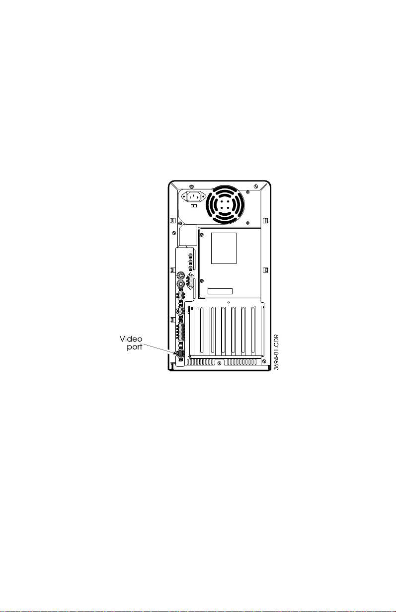
To connect a monitor to the computer:
Set up your monitor according to the instructions that
1.
accompany it.
Connect the monitor interface cable to the video port on
2.
the back of the computer (Figure 1), or to the add- in video
connector if you have installed a video adapter.
To use a multifrequency monitor in standard VGA mode,
3.
set the monitor to analog mode.
Plug the monitor power cord into a grounded outlet.
4.
Figure 1. Video Port Location
Connecting the Keyboard, Mouse, and
Peripheral Devices
If a plastic cap covers the end of the keyboard cable, remove it.
Plug the keyboard and mouse into their connectors at the back
of the computer. Be sure that the arrows on the cable plugs point
to the right as you face the rear of the system.
6 Advantage! 9000 Series User’s Manual
Page 14
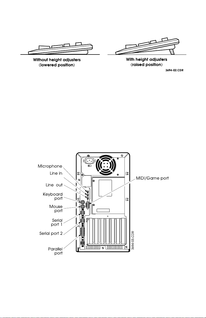
To adjust the height of the keyboard, flip the height adjusters on
the bottom of the keyboard up to the raised position (Figure 2).
Figure 2. Adjusting Keyboard Height
Two serial ports and one parallel port are located on the back
panel of the computer (Figure 3). Connect serial peripheral
devices to these ports. For instance, a printer commonly
connects to the parallel port, but some types connect to a serial
port.
The audio and peripheral ports are also located on the rear panel
of the computer. The rear panel Microphone port is disabled: To
add a microphone, use the modem’s port illustrated in the
Getting Started guide.
Figure 3. Rear Panel Connectors
Setting Up Your Computer 7
Page 15
If you are uncertain how to connect a peripheral device, see the
documentation that accompanied it. Information on connecting
your speakers is provided in your Getting Started guide.
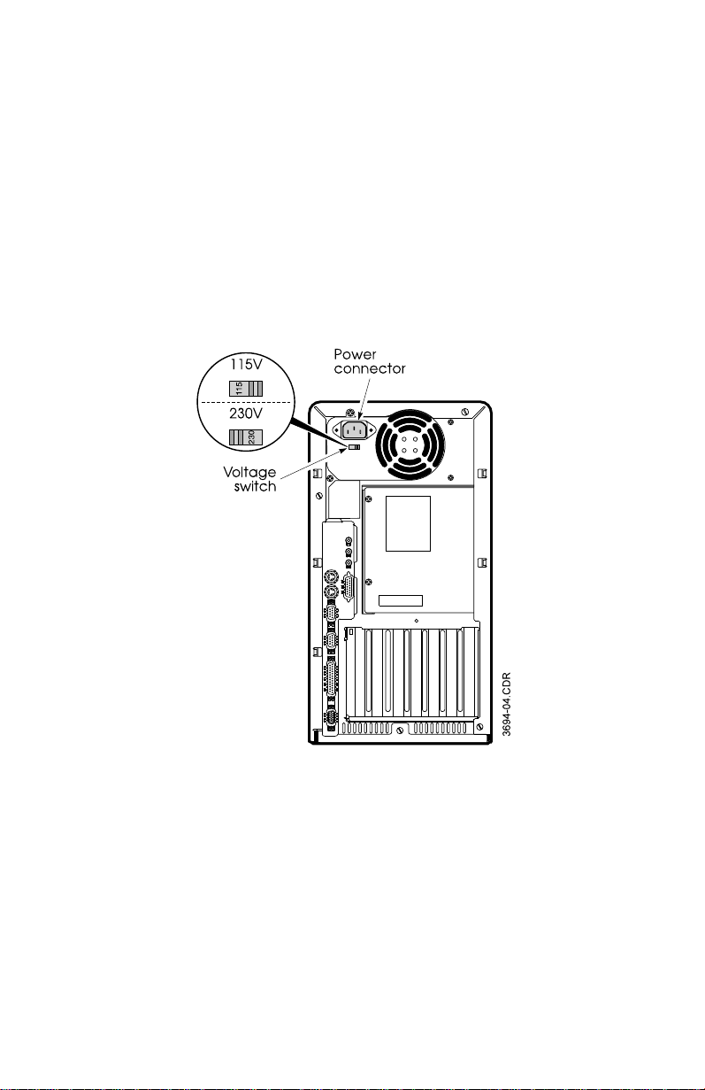
Connecting the Power Cord
Check that the voltage switch on the power supply is set to the
appropriate voltage: 115 V or 230 V (Figure 4). Plug one end of
the power cord into the power connector on the rear of the
computer and the other into a grounded outlet.
Figure 4. Power Connector Location
Turning the Computer On
Before turning the computer on, press the power button on the
monitor. (For its location, see the monitor’s user manual.) The
computer power button is located at the upper-right corner of
8 Advantage! 9000 Series User’s Manual
Page 16
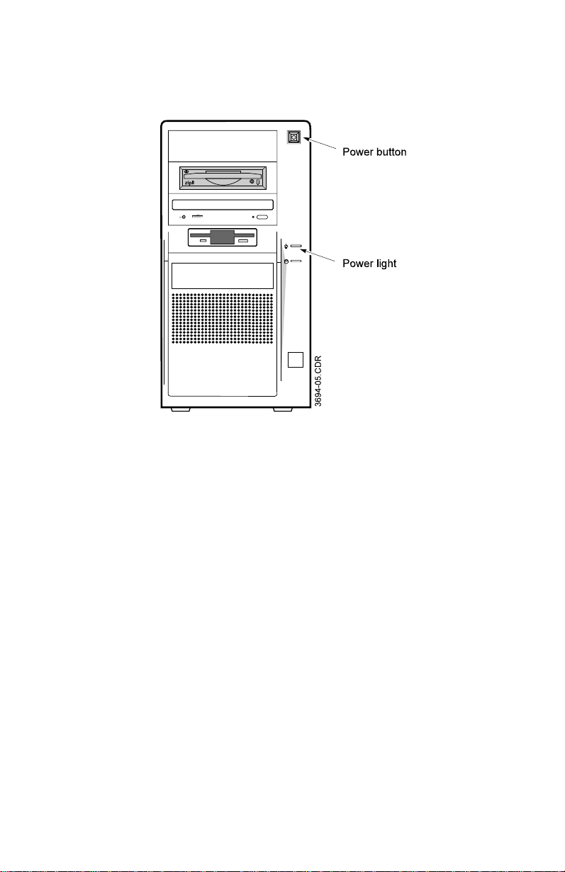
the front panel (Figure 5). Press it to turn the computer on. While
the computer is on, the green power light on the front panel of
the computer should be on.
Figure 5. Power Button and Light
As the computer starts, messages appear on the monitor screen.
Note the prompt to run System Setup, a program that configures
your system.
Once the computer is on, you can:
•
Make master disks of the programs installed on your
computer’s hard drive.
•
Use System Setup to configure the computer (see “Using
System Setup” on page 43).
•
Begin using the computer hardware (see “For the FirstTime User” on page 12).
You can also install and use application programs that you have
purchased for the computer. See the instructions that
accompany the application programs.
When you have finished using the computer, exit all
applications, shut down Windows 95, and press the power
buttons to turn the computer and monitor off.
Setting Up Your Computer 9
Page 17

Using Your Computer’s Power Management Features
Your computer has an advanced power management feature
that enables it to automatically save power when it is not in use.
“Not in use” is defined as a period during which your computer
receives no input from the keyboard or mouse. When your
system goes into its power management mode, it will blank the
monitor screen, spin down the hard drive, and put the CPU into
an “idle” mode.
To wake the system up, press any key on the keyboard or move
the mouse. If the password is enabled, enter the password, then
move the mouse or press a key.
Power conservation is most effective with DPMS monitors and
hard drives.
Your system comes configured from the factory with the
advanced power management feature enabled and set to 30
minutes. This means that the computer will go into its power
management mode if it does not receive any keyboard or mouse
input for 30 minutes.
Some Considerations on Using Power Management
If your computer is engaged in activities that require no
keyboard or mouse input for long periods of time, you can either
increase the delay period or turn off the advanced power
management mode. Under certain conditions, power
management may automatically start, interrupting what your
computer is doing at the time. Some examples of usage which
may lead to this condition include:
•
Playing games that use only the joystick
•
Transferring long files over your modem or infrared
receiver (available on some models)
•
Printing long documents
•
Making tape backups of your data
10 Advantage! 9000 Series User’s Manual
Page 18

•
Using programs that schedule events for unattended
operation
See “Power Management Configuration” on page 51 for the
procedure for changing the inactivity timer for power
management.
Be sure to set the Inactivity Timer field to a period of
time greater than any activities which may be
interrupted by the power management feature.
Disabling Power Management
It is not necessary to go into System Setup to disable power
management. Power management can be disabled from within
Windows
Power management should now be disabled.
®
95. To disable power management:
Click on the Start button on the Task Bar, then Settings,
1.
then Control Panel.
Double-click on the Power icon to open the Power window.
2.
From within the field labeled “Power Management,” select
3.
“none.”
Setting Up Your Computer 11
Page 19

For the First-Time User
This section provides basic information about using the
keyboard, mouse, drives, and other features of your computer.
Using the Keyboard
Your system includes an upgraded Windows 95 keyboard,
which features special software application keys for use with
Windows 95.
The four types of keys found on your keyboard are shown in
Figure 6.
Figure 6. Keyboard Layout
12 Advantage! 9000 Series User’s Manual
Page 20

Using the Mouse
Your computer comes with a PS/2-type port for connecting the
mouse that came with your system. This port also supports
other PS/2-compatible pointing devices.
Optionally, you can attach a serial mouse, but doing so will
occupy a serial port.
The function of different mouse types varies. Refer to the
device’s user manual for more information. Keep the following
in mind while using a mouse:
•
Use the mouse on a level surface, such as a mouse pad. A
mouse pad provides better traction and a cleaner surface
than a desktop.
•
Be sure there is enough work space in which to move the
mouse.
•
Keep the contact portion of the mouse free from dust,
lint, or hair. You may occasionally need to remove the
mouse roller ball and clean the contacts inside the mouse
if cursor movement becomes erratic.
•
If you use the mouse constantly, give your mouse hand
an occasional break.
Using Disks
A computer stores information on floppy or hard disks. A
computer retrieves information from these disks, as well as CDROM discs if your computer has a CD-ROM drive installed. The
operating system determines how you use disks. For more
information, read the user’s manual for your operating system.
Using Floppy Disks
The computer comes with a 3.5-inch, high-density drive. You
can install another floppy drive, either 3.5- or 5.25-inch.
For the First-Time User 13
Page 21

Your 3.5-inch drive can:
•
Read, write, and format 3.5-inch, high-density disks. This
type of disk stores up to 1.44 MB of data.
•
Read, write, and format 3.5-inch, double-density disks.
This type of disk stores up to 720 KB of data.
The capability of a 5.25-inch floppy drive depends on whether it
is high-density or low-density:
•
The high-density drive can read, write, and format 5.25inch, high-density disks. This type of disk stores up to 1.2
MB of data.
•
Either type of drive can read, write, and format 5.25-inch,
double-density disks. This type of disk stores up to 360
KB of data. Data written on a 360-KB disk in a highdensity drive may not be readable in a double-density
drive.
Floppy disks are designed so that you can easily insert one into
the computer when you need it, and then remove it when you
are finished with it. With the 3.5-inch drive, simply insert the
disk; push the button on the drive to eject the disk. If you install
a 5.25-inch drive, insert a disk and then flip the drive lever down
to lock the disk in place; flip the lever up again to remove the
disk.
A light near the floppy disk drive opening (Figure 7) comes on
when the computer reads from or writes to a floppy disk.
Do not remove a disk or turn the system off when this
light is on – you may damage the disk and its data.
For more information about your Zip drive and disk use,
see the Zip drive’s
14 Advantage! 9000 Series User’s Manual
User’s Guide
.
Page 22

Figure 7. Drive Activity and Status Lights
Once information is saved to a floppy or Zip disk, it remains
there until it is overwritten or erased, or the disk is formatted.
Turning off the computer does not affect this data.
Using Hard Disks
Unlike a floppy disk, a hard disk (also called a fixed disk) is
installed inside the computer and is not meant to be removed
routinely. While the storage capacity of hard disks varies
according to model, any hard disk holds much more than a
floppy. Also, the computer reads and works with a hard disk
more rapidly than with a floppy disk.
While the hard drive is searching for information, or storing
information to the disk, the hard drive activity light on the front
panel of the computer (Figure 7) is on.
Once information is stored on a hard disk, it remains there until
it is overwritten. Turning off the computer does not affect the
data.
For the First-Time User 15
Page 23

Using Zip Disks
Your computer comes with a 100MB Iomega® Zip™ drive. This
drive functions in a manner similar to the 3.5 inch drive, but
with an increased capacity of 100MB per disk. A formatted tools
disk is included with your computer. You store information on
and retrieve data from Zip disks as you would the 3.5 inch disks.
For more information about your Zip drive, see its user’s guide.
Using Compact Discs
Your computer comes with a CD-ROM drive. This drive
retrieves data and runs programs stored on compact discs.
Like floppy disks, compact discs are designed so that you can
easily insert one into the computer when you need it, then
remove it when you are done. Press the button on the CD-ROM
drive, and its tray slides out. (Do not lean on the tray; it does not
support much weight.) Insert a CD, label side up (or remove a
disk, if you have finished using it). Then press the button again
or gently push the tray in to close the drive tray.
Install and start a CD-based program as you would any other.
Generally, the name of a CD-ROM drive is the letter following
the letter assigned to your last hard drive. For instance, if you
have one hard drive, it is drive C and your CD-ROM is drive D.
See your operating system or Windows documentation for more
information on running programs.
The laser beam used in CD-ROM drives may be harmful
to the eyes - do not attempt to disassemble the CD-ROM
drive. Service should be performed by qualified
personnel only. Do not place reflective objects other than
a CD in the disc slot, due to possible hazardous radiation
exposure.
Restarting the Computer
You can restart (reboot) the computer in three ways:
•
From within Windows 95, restart the computer by:
Clicking on the Start icon
a.
Selecting “Shut Down.”
b.
16 Advantage! 9000 Series User’s Manual
Page 24

When the “Shut Down Windows” dialog box
c.
appears, select the “Restart the Computer” option,
then press the “Yes” button.
This is the preferred method for restarting your
computer (assuming your system is working
normally), because it allows Windows 95 to save
configuration information and shut down in an
orderly manner before it restarts. However, if your
system has become erratic or nonresponsive (i.e.,
“crashed”), you should:
•
Press <Ctrl+Alt+Del> twice to perform a warm (or soft)
boot. A warm boot clears system memory and restarts
the computer.
•
If the computer still does not respond, you must do a
cold (or hard) boot: press the power button to turn the
power off, wait ten seconds, then press the power button
again to turn the power on. If a password has been
assigned, you will be required to enter it.
When you restart the system, you lose any data that you
have not saved.
For the First-Time User 17
Page 25

Upgrading Your Computer
You can enhance the capabilities and performance of your
computer by installing upgrade components. You can install
any of the following components:
•
8- or 16-bit ISA-compatible add-in boards.
•
32-bit PCI-compatible add-in boards.
•
A video adapter board. However, the computer includes
built-in 64-bit VGA hardware, which provides enhanced
video and graphics capabilities without using an
expansion slot. Install a video adapter board only if you
do not want to use built-in VGA.
The computer is compatible with most ISA- or PCIcompatible video adapters, including CGA, EGA, VGA,
SVGA, and specialized video adapters.
•
A 3.5- or 5.25-inch floppy drive.
•
A tape-backup drive.
•
A 3.5-inch half-height IDE hard drive.
•
Additional system memory.
•
Additional Video memory
•
An upgrade Intel microprocessor.
As part of the upgrade process, you may need to change the
system configuration by setting jumpers or running the System
Setup program. See “Configuring Your Computer” on page 41
for more information.
If you are not familiar or comfortable with add-in board,
floppy drive, hard drive, SIMM or chip handling and
installation procedures, ask an authorized AST service
technician to upgrade your system. In no case will AST
Research, Inc., be liable for damage to the system and its
components, or loss of data, caused by improper or
faulty installation. Contact your AST reseller for the
location of the nearest AST authorized service center.
18 Advantage! 9000 Series User’s Manual
Page 26
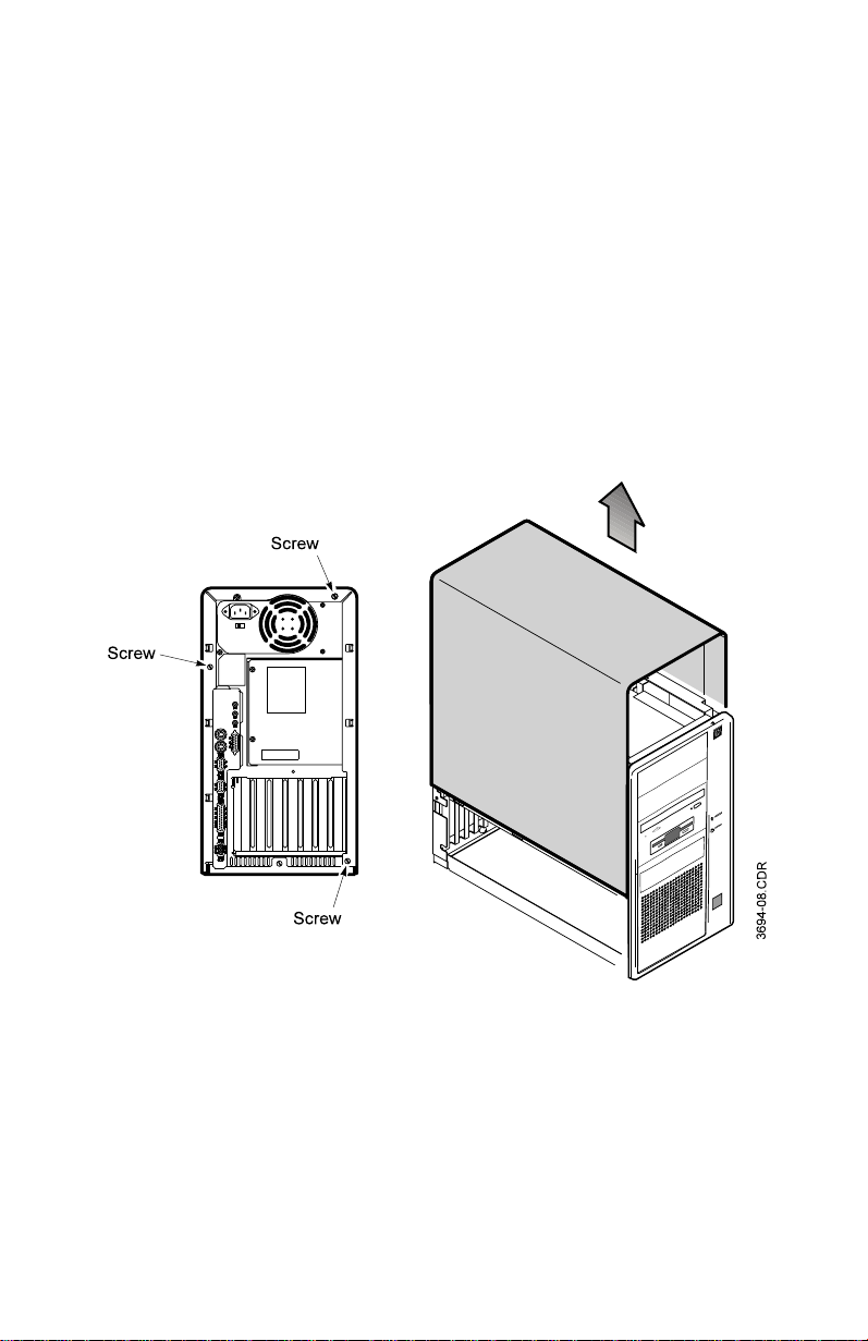
Removing the System Cover
Before installing internal components, you must turn off and
unplug the computer, and remove the system cover.
To remove the system cover:
If the computer is on, turn it off.
1.
Unplug the power cord and disconnect any peripheral
2.
devices.
Loosen the three thumbscrews on the rear of the system
3.
(Figure 8). If the screws are too tight to remove by hand,
use a flat-bladed screwdriver to loosen them.
Figure 8. Removing the System Cover
Slide the cover back approximately one-half inch, until a
4.
space opens between the front of the cover and the front
of the system.
Upgrading Your Computer 19
Page 27

Lift the cover straight up until it clears the system. Set it
5.
aside.
Removing the Front Panel
To remove the front panel of the system:
Push in the three tabs that attach the left side of the front
1.
panel to the chassis (Figure 9).
Figure 9. Removing the Front Panel
Swing the front panel to the right.
2.
Pull out the front panel until the tabs on the right side of
3.
the front panel clear their slots.
20 Advantage! 9000 Series User’s Manual
Page 28

Replacing the System Cover
After adding optional components and making adjustments,
replace the system cover. Follow these steps:
Make sure you have not left any tools or loose parts inside
1.
the system. Make sure everything is properly installed
and tightened.
Lower the cover straight down over the chassis.
2.
Slide the cover forward until the rear of the cover aligns
3.
with the rear of the chassis. Make sure the cover screws fit
into the notches on the sides of the system cover.
Tighten the screws on the rear of the system.
4.
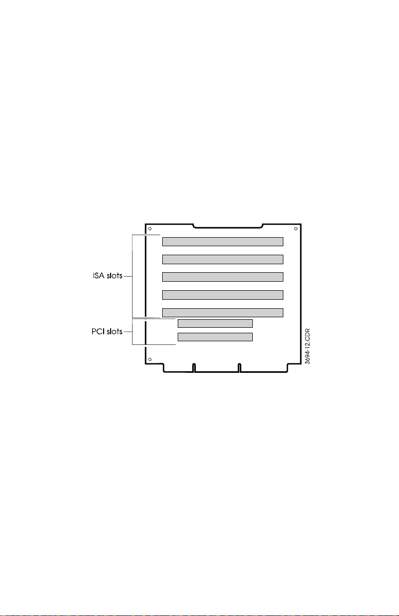
Installing Add-in Boards
The computer has expansion slots for installing add-in boards,
such as modems, sound cards, or video adapters. The system
has five 16-bit ISA slots and two 32-bit PCI slots.
The expansion slots are on a circuit board, called the riser card,
which is perpendicular to the system board.
Removing the Bottom Panel
Before adding or removing cards from your system, you will
need to remove the bottom panel. To remove the bottom panel
of the system:
Gently tilt the system onto its right side (as you face the
1.
front of the system).
Upgrading Your Computer 21
Page 29

Figure 10. Removing the Bottom Panel
Remove the screw that holds the bottom panel in place
2.
(Figure 10).
Slide the bottom panel toward the rear of the system until
3.
the two tabs at the bottom front of the system clear their
slots.
Remove the bottom panel from the chassis.
4.
Board Installation
Follow this procedure to install an add-in board.
Run any software that is required before installing the
1.
board:
•
If you are installing an ISA add-in board that does not
comply with the Plug and Play specification, you will
need to configure it manually, using the Windows 95
Add New Hardware Wizard. See your Windows 95
documentation for more information.
•
If you are installing an ISA or PCI add-in board that
complies with the Plug and Play specification, the
board is ready to install.
22 Advantage! 9000 Series User’s Manual
Page 30
•
You may need to run an installation program
provided by the board manufacturer before or after
installing or removing an add-in board. Refer to the
board documentation for more information.
Turn the computer off, unplug the power cord,
2.
disconnect all peripheral devices, and remove the system
cover (see “Replacing the System Cover” on page 21).
Set all the necessary jumpers or switches on the add-in
3.
board. See the add-in board documentation for details.
Determine whether your add-in card is a PCI or ISA card,
4.
then select an unused expansion slot (Fi gure 11). Be aware
that any cables that attach the add-in board to the system
board must be threaded around the riser card.
Figure 11. Riser Card Slot Locations
Remove the bracket screw and the bracket for the selected
5.
expansion slot.
Install the add-in board:
6.
Line up the board with the expansion slot (Figure
a.
12).
Upgrading Your Computer 23
Page 31

Figure 12. Installing an Add-in Board
Insert the board until its edge connector is aligned
b.
with an expansion-slot receptacle.
Using evenly distributed pressure, push the board
c.
straight in until it is fully inserted in the slot.
Reinstall the bracket screw you removed in step 5.
d.
Attach any cables needed to connect the add-in board to
7.
internal components. For more information, see the
manufacturer’s user’s manual. Note the following:
•
If the board requires a cable to be attached to a device
on the other side of the chassis, a slot on the riser card/
fan support provides a way to route cables without
interfering with the system cover.
•
If the board is a video-capture or other video board
that requires a pass-through VGA connection, connect
the pass-through cable to the VESA feature connector
(see the illustration in the back of this manual).
Replace the bottom panel. Set the system upright and
8.
replace the system cover. Reconnect peripheral devices,
plug in the power cord, and boot the system.
24 Advantage! 9000 Series User’s Manual
Page 32

Run any configuration software required to complete the
9.
installation of the add-in board.
Configuring Add-in Parallel Ports and Sound Cards
If you install an add-in board with a parallel port, it must be
configured to use an interrupt other than IRQ7, since that
interrupt is reserved for the onboard parallel port. Optionally,
you can disable the onboard parallel port. Refer to the Peripheral
Configuration section of the Advanced Options part of System
Setup for more information.
If you install an add-in sound card, disable the integrated audio
adapter. Refer to the Audio Configuration section of the
Advanced Options part of System Setup for more information.
Installing Drives
One 3.5-inch floppy drive, one 3.5-inch hard drive, one Zip
drive, and one CD-ROM drive come with your computer. You
can add one additional floppy drive and one additional IDE
drive. Examples of additional drives are:
•
Half-height 3.5- or 5.25-inch floppy drives. The system
board has a floppy controller that supports up to two
floppy drives, one of which is the 3.5-inch drive that
comes with the computer.
•
Half-height 3.5- or 5.25-inch hard drives.
The system board has two IDE connectors that support
up to two drives each.
To use another type of hard drive, such as a SCSI drive,
install an add-in hard drive controller board.
•
Tape backup. Some models of tape backup drive can use
the onboard floppy controller; other models require addin controllers.
Before installing a drive, read the instructions for preparing the
drive. You can then install a drive on any of the drive- mounting
brackets located inside the computer (Figure 13).
Upgrading Your Computer 25
Page 33

Figure 13. Drive Bay Locations
You can install these drives in a front drive bay or a rear drive
bay:
•
A 3.5-inch floppy drive comes attached to the underside
of the front drive bay. The CD-ROM is mounted in the
bottom slot of the bay, and the Zip drive is located in the
middle slot directly above the CD-ROM drive. The bay
can hold an additional drive in the upper slot, positioned
so that it is accessible from outside the computer. Install
a floppy or a tape-backup drive there.
•
The rear drive bay contains an IDE hard drive and space
for two additional drives, positioned so that they are
inaccessible from outside the computer. Install only hard
drives there.
The system board has three connectors to support the additional
drives you may install:
•
A built-in floppy controller that supports up to two
floppy drives, one of which comes installed on your
system.
•
Two IDE connectors, each of which supports up to two
IDE devices. The Primary connector supports your hard
26 Advantage! 9000 Series User’s Manual
Page 34

drive, and has one additional connector available. The
Secondary connector supports your CD-ROM as a
master and your Zip drive as a slave. To locate these
connectors, see the illustration in the back of this manual.
Preparations for Installing Drives
To avoid accidental discharge of static electricity as you
handle components or switches, use a grounding wrist
strap, or refer this procedure to qualified service
personnel.
As you install drives, keep the following in mind:
•
AST tests the drives it distributes to ensure that they are
compatible with AST computers. These drives are
recommended for use in this system.
•
To ensure that a newly installed drive is properly
grounded, tighten all screws completely.
To prepare a drive for installation, read the documentation that
came with it. Also do the following:
•
Note its capacity in kilobytes or megabytes.
•
For a tape-backup drive, configure the device in
accordance with the instructions that came with the
drive.
•
For an IDE hard drive, position the drive-select jumper to
configure the drive as master or slave. Your system ships
with the hard drive as master, and the master should be
the drive from which the system boots.
•
If a hard drive has a defect list, copy down the
information and save it.
Installing a Drive in the Front Drive Bay
To install the drive:
Turn the computer off, unplug the power cord, and
1.
disconnect all peripheral devices. Remove the system
cover and the front panel (see “Replacing the System
Cover” on page 21 and “Removing the Bottom Panel” on
page 21).
Upgrading Your Computer 27
Page 35
If you are installing a drive that requires an add-in
2.
controller, install the controller board (see “Installing
Add-in Boards” on page 21).
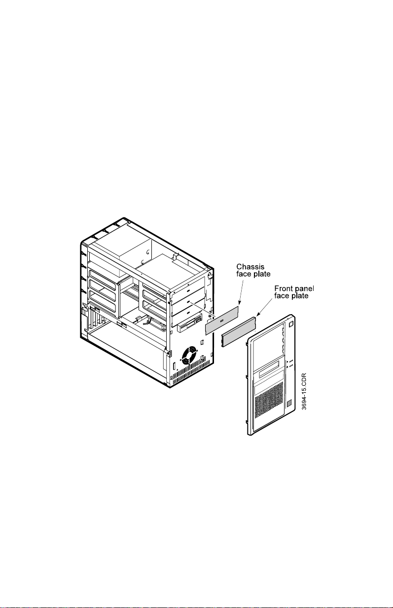
Remove a face plate from the front panel and the
3.
corresponding face plate from the chassis (Figure 14):
From the front of the front panel, press on the
a.
sides of the face plate until it comes out of the
panel.
Select the face plate on the chassis that
b.
corresponds to the face plate you removed from
the front panel. Insert a screwdriver into the slot in
the center of the face plate, and twist it until the
face plate pops off the chassis.
Zip drive not shown in this illustration.
Figure 14. Accessing the Front Drive Bay
Attach one guide rail to each side of the drive:
4.
A metal grounding clip should be attached to each
a.
guide rail on the side that faces the drive. If the
grounding clip has not been attached, slide the
grounding clip over the round mounting hole. The
28 Advantage! 9000 Series User’s Manual
Page 36
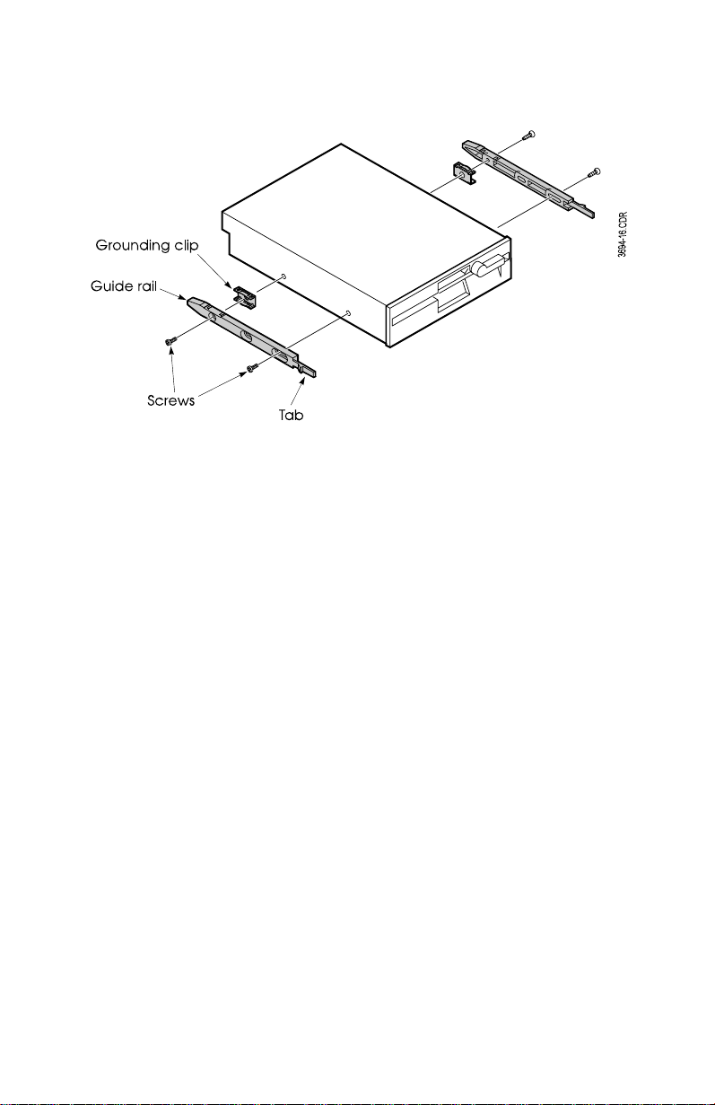
clip fits into indentations at the top and bottom of
the rail and snaps into place (Figure 15).
Figure 15. Installing Guide Rails
Position each guide rail so that the end with the
b.
tab faces the front of the drive, and the grounding
clip is next to the drive. Align the mounting holes
on the drive with the holes on the guide rail.
Attach the guide rails to each side of the drive by
c.
installing four mounting screws (Figure 15).
Slide the drive into the bay, until the tabs on the guide
5.
rails snap into the slots on the drive bay (Figure 16). To
remove a drive, press the tabs on the guide rails until the
drive slides freely.
Upgrading Your Computer 29
Page 37

Zip drive not shown in
this illustration.
Figure 16. Inserting a Drive Into A Drive Bay
Attach a cable (Figure 17) from the power supply to the
6.
drive, then attach a controller cable:
Figure 17. Drive Cables
•
To use the built-in floppy controller, connect the
controller cable that extends from the floppy drive
controller connector on the system board (see the
illustration in the back of this manual).
30 Advantage! 9000 Series User’s Manual
Page 38

•
If you are installing a second hard disk or other device
with an IDE interface, connect it to an IDE interface
connector on the system board. If only a single hard
drive is connected to the primary IDE controller (your
shipping configuration), you can connect a new hard
drive there. To locate the IDE connectors, see the
illustration in the back of this manual.
•
To use an add-in controller board, connect the drive to
the controller cable extending from the controller board.
See the documentation for the add-in controller board for
more information.
Each controller cable has an indicator (typically a colored
7.
stripe) along one side, and the edge connector on the cable
has a small triangle on the same side as the stripe. The
connector on the drive has a notch on one side. As you
connect the cable to the drive, the stripe, triangle, and
notch belong on the same side. If the cable connector does
not fit easily on the drive connector, check that you have
positioned the stripe correctly. Do not force the cable
connector. For the locations of the system board
connectors, see the illustration in the back of this manual.
Replace the front panel: Insert the tabs along the right
8.
edge of the front panel into their openings on the system.
Swing the front panel shut, using its right edge as an axis,
until the tabs along the left edge of the front panel snap
into place.
Replace the system cover. Reconnect peripheral devices
9.
and plug in the power cord. Turn on the system.
If you have installed a floppy drive or hard drive, run
10.
System Setup and indicate the drive. You do not need to
run System Setup if you have installed a drive that uses an
add-in controller.
After installing a new hard drive, refer to the
11.
documentation that came with your drive to determine
whether you need to partition and format it. Refer to your
Windows 95 documentation for details on partitioning
and formatting the hard drive.
Upgrading Your Computer 31
Page 39
Do not perform a low-level format on an AST IDE drive;
you might damage the format data. IDE drives sold by
AST have been low-level formatted at the factory.
You do not need to perform FDISK or FORMAT on the
hard drive that came with your computer. If you ever need
to repartition or reformat this hard drive, back up its data
first. Partitioning and formatting a hard drive deletes all
of the data on it
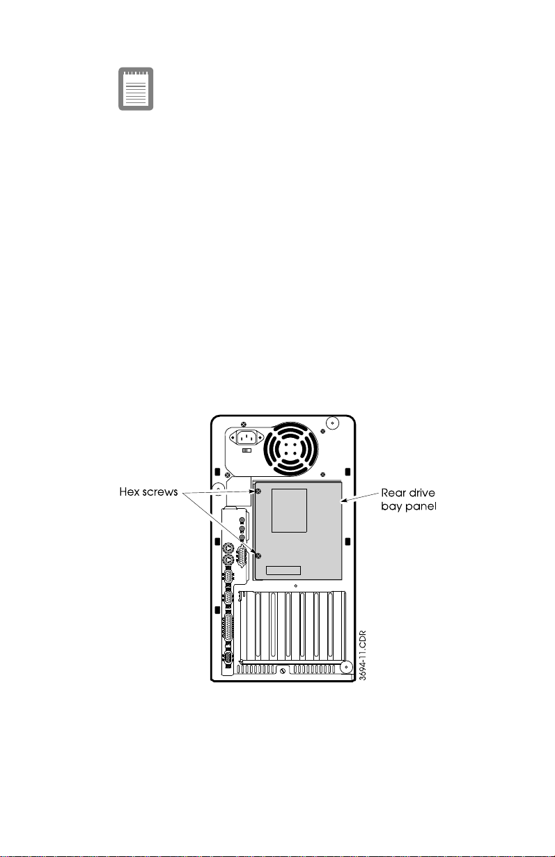
Installing a Drive in the Rear Drive Bay
Before installing a drive in the rear drive bay, you must first
remove the rear drive bay panel.
Removing the Rear Drive Bay Panel
To remove the rear drive bay panel from the back panel of the
system:
Remove the two screws on the left edge of the rear drive
1.
bay panel (Figure 18).
Figure 18. Removing the Rear Drive Bay Panel
Lift the panel off the chassis.
2.
32 Advantage! 9000 Series User’s Manual
Page 40

After adding optional components and making adjustments to
the system, replace the cover and access panels by reversing the
removal procedures.
Installing the Drive
Turn the computer off, unplug the power cord, and
1.
disconnect all peripheral devices. Remove the system
cover and rear drive bay panel (see “Removing the
System Cover” on page 19).
Attach a guide rail to each side of the drive. Attach each
2.
rail to the bottom set of holes on the drive. Align each rail
so its tapered end is close to the back of the drive.
Slide the drive into the bay until it snaps into place. (To
3.
remove a drive, press the tabs on the guide rails until the
drive slides freely.)
Attach a power-supply cable to the drive, then attach the
4.
primary IDE controller cable to the drive. Refer to the
appropriate step in “Installing a Drive in the Front Drive
Bay” on page 27 for details.
Close the rear panel, and reinstall the screws you
5.
removed in step 1. Replace the system cover. Reconnect
peripheral devices and plug in the power cord. Turn on
the system.
If you have installed a hard drive, run System Setup and
6.
use the hard-disk type field under the appropriate menu
– Primary Hard Drives or Secondary Hard Drives – to
configure the drive. You do not need to run System Setup
if you have installed a drive that uses an add-in controller.
After installing a new hard drive, refer to the
7.
documentation that came with your drive to determine
whether you need to partition and format it. If you are
using DOS, perform FDISK and FORMAT (refer to your
DOS documentation for details).
When using FDISK and FORMAT, make sure you are
addressing the new drive, and not an existing drive that
contains data. FDISK and FORMAT will delete all data on
a hard drive.
Upgrading Your Computer 33
Page 41

If you are using a different operating system, see its
documentation for partitioning and formatting the hard drive.
Do not perform a low-level format on an AST IDE drive; you
might damage the format data. IDE drives sold by AST have
been low-level formatted at the factory.
You do not need to perform FDISK or FORMAT on the
hard drive that came with your computer. If you ever need
to repartition or reformat this hard drive, back up its data
first. Partitioning and formatting a hard drive deletes all
of the data on it.
Adding System Memory
By installing SIMMs on the system board, you can increase the
amount of system memory to a maximum 128 MB. This
generally improves computer performance, especially for
graphics- and computation-intensive programs.
Purchase SIMMs from your AST reseller. Use only the SIMMs
that AST has specified for your computer. Otherwise, your
computer may malfunction. Make sure the SIMMs meet the
following specifications:
•
72 tin-plated pins
•
32 bits
•
Single- or double-sided
•
+5V
•
70 ns fast page mode or 60 ns EDO DRAM.
Memory Configurations
The system board has two banks of SIMMs, Bank 0 and Bank 1.
You can use SIMMs of the following sizes:
•
4 MB (1M x 32)
•
8 MB (2M x 32)
•
16 MB (4M x 32)
•
32 MB (8M x 32).
34 Advantage! 9000 Series User’s Manual
Page 42
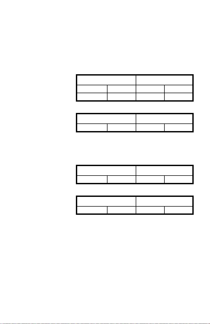
Minimum memory configuration is 8 MB, and maximum is 128
MB. You can mix different sizes of SIMMs to achieve a wide
variety of memory configurations, as long as you adhere to the
following rules:
•
You must use the same size and type of SIMM in both
slots of bank 0 or bank 1. The following examples show a
correct and an incorrect configuration:
Correct:
Bank 0 Bank 1
4 MB 4 MB 2 MB 2 MB
2 MB 2 MB 4 MB 4 MB
Incorrect:
Bank 0 Bank 1
4 MB 2 MB 4 MB 2 MB
•
Banks cannot be partially populated (i.e., a SIMM in one
slot, and none in the other). For example:
Correct:
Bank 0 Bank 1
4 MB 4 MB Empty Empty
Incorrect:
Bank 0 Bank 1
4 MB Empty 4 MB Empty
Adding and Removing SIMMs
To add a SIMM, or to replace an existing SIMM, complete these
steps:
Turn the computer off, unplug the power cord,
1.
disconnect all peripheral devices, and remove the system
cover.
Upgrading Your Computer 35
Page 43

To access the SIMM slots, you must first remove the rear
2.
drive bay:
Remove the rear drive bay panel (see “Removing
a.
the Rear Drive Bay Panel” on page 32).
Remove any drives that may be mounted in the
b.
rear drive bay panel by pressing in on the tabs on
the drive rails and pulling the drives out of the
drive bay.
Slide the drive cage out of the tabs that secure it to
c.
the chassis, and remove from the chassis.
Locate the SIMM slots on the system board. Refer to the
3.
illustration in the back of this manual.
If necessary, remove any add-in boards that block easy
4.
access to the SIMM slots.
If you need to remove a SIMM, carefully pull the retaining
5.
clips from the edges of the SIMM (Figure 19). At the same
time, push the SIMM slightly forward from the back.
Remove the SIMM carefully to avoid damage.
36 Advantage! 9000 Series User’s Manual
Page 44
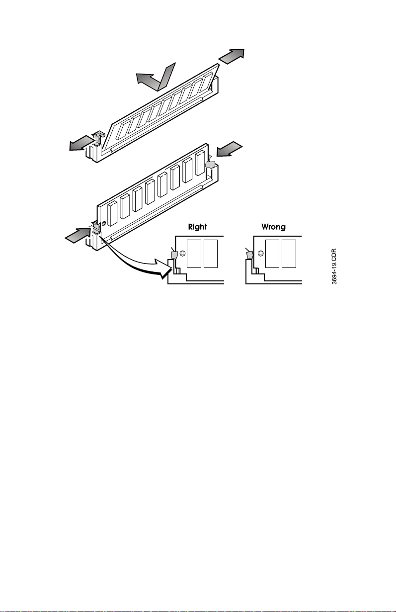
Figure 19. Installing a SIMM
To install a SIMM, slide it into the first empty bank and
6.
push it back until the retaining clips snap into place
(Figure 19). Make sure the SIMM is securely in its bank.
If you removed any add-in boards to reach the SIMM
7.
banks, replace the add-in boards.
Replace the system cover. Reconnect peripheral devices
8.
and plug in the power cord. Turn on the system.
Upgrading the Microprocessor
The system board has a ZIF microprocessor socket for installing
an upgrade Intel microprocessor for enhanced system
performance.
To install an upgrade Intel microprocessor in the socket, do the
following:
Upgrading Your Computer 37
Page 45
Turn the computer off, unplug the power cord, and
1.
disconnect all peripheral devices.
Remove the system cover (see “Removing the System
2.
Cover” on page 19).
Carefully lay the system over on its right side.
3.
Remove any add-in boards (see “Installing Add-in
4.
Boards” on page 21) that may block access to the
microprocessor socket.
Locate the microprocessor ZIF socket (see the illustration
5.
in the back of this manual).
When you install the microprocessor, do not touch the
edges of the empty bracket for the 3.5-inch floppy drive.
The edges are sharp.
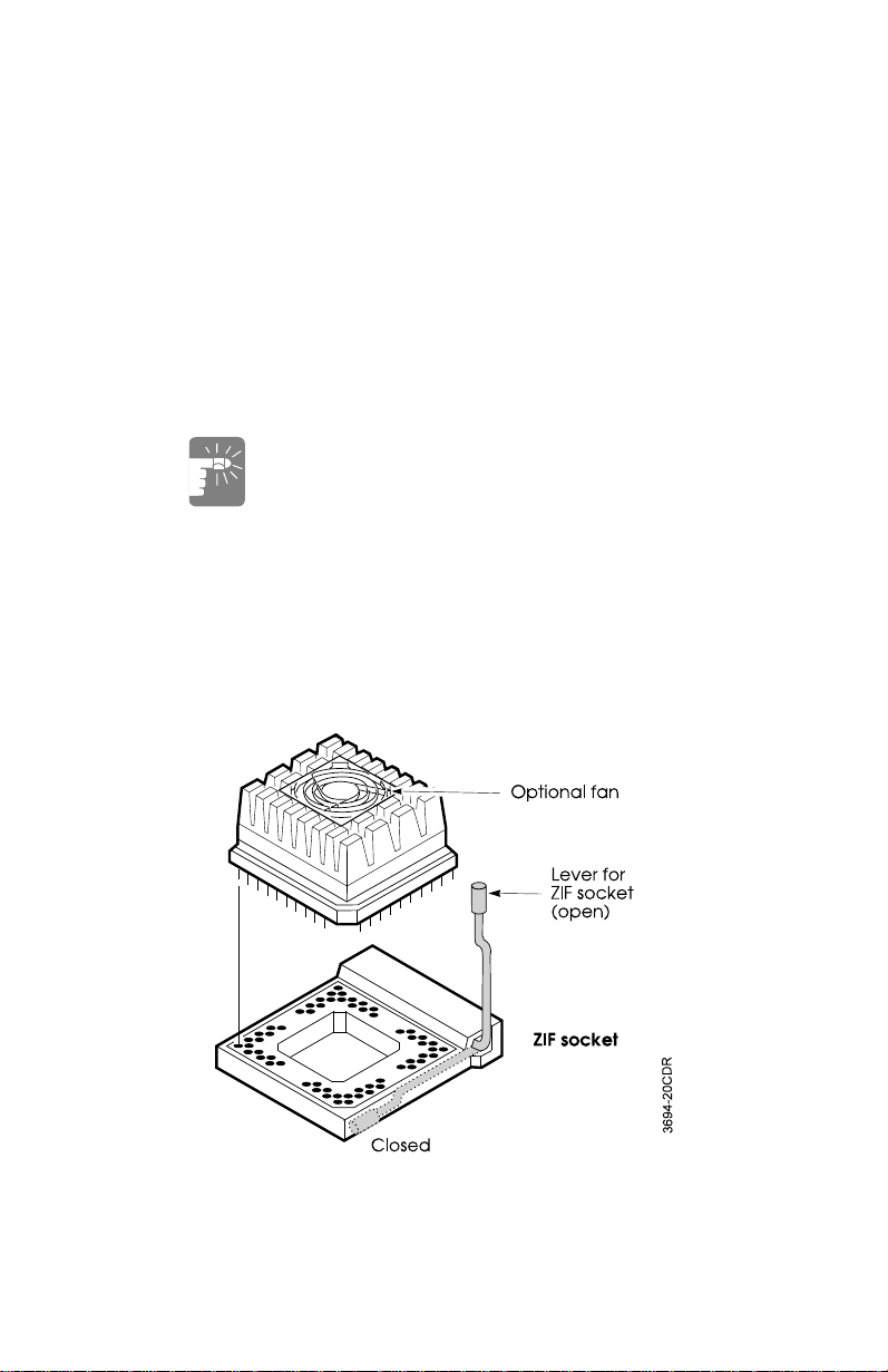
Insert the microprocessor into the socket (Figure 20):
6.
Locate the lever on the side of the socket. Pull the
a.
lever slightly away from the socket, then upward
until it is perpendicular to the system board.
Remove the existing microprocessor and store it in
an antistatic bag.
Figure 20. Installing the CPU
38 Advantage! 9000 Series User’s Manual
Page 46

Align the beveled edge of the upgrade
b.
microprocessor with the beveled edge on the
microprocessor socket.
Insert the microprocessor in the socket. Be careful
c.
not to bend any pins.
Push the lever down to secure the microprocessor.
d.
Be sure to fasten the lever under the retaining clip
on the side of the socket.
Set the system upright and replace its cover. Reconnect
7.
peripheral devices and plug in the power cord. Turn on
the system.
Adding Video Memory
Your computer has video memory sockets that enable you to
upgrade the system from 1 MB to 2 MB of video memory. To
add video memory, obtain a video upgrade kit from your AST
reseller.
To install the video memory devices, do the following:
Turn the computer off, unplug the power cord, and
1.
disconnect all peripheral devices. Remove the system
cover (see “Removing the System Cover” on page 19).
Gently tilt the system onto its right side (as you face the
2.
front of the system).
If add-in boards are installed in the system, you will need
3.
to remove them to access the video memory sockets. See
“Installing Add-in Boards” on page 21 for information on
removing add-in boards.
Locate the two empty video memory sockets (see the
4.
illustration in the back of this manual) on the system
board.
Install the video memory chips by aligning each device
5.
with its socket (Figure 21).
Upgrading Your Computer 39
Page 47
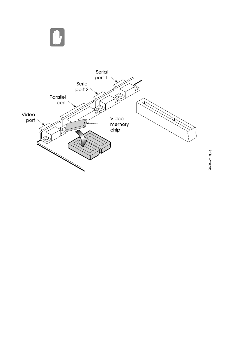
Each device has a small round depression, or a notch in
the end that corresponds to the beveled corner of the
socket. Make sure the chips are correctly oriented to
their sockets before inserting them, or damage to the
chips, the computer, or both may result.
Figure 21. Adding Video Memory
Press each device until it is completely inserted in the
6.
socket.
If you removed add-in boards, replace them.
7.
Set the system upright and replace the system cover (see
8.
“Replacing the System Cover” on page 21). Reconnect
peripheral devices and plug in the power cord. Turn on
the system.
The system automsteatically detects and uses the additional
video memory.
40 Advantage! 9000 Series User’s Manual
Page 48

Configuring Your Computer
This section shows how to change the system configuration by
setting system board switches, running System Setup, setting
passwords, and updating the BIOS.
Setting Jumpers
The system board contains jumpers that you can use to change
the system configuration. You may need to change these jumper
settings to prevent conflicts with an add-in board you just
installed or to enable or disable passwords. See the illustration
in the back of this manual for the location of the jumpers.
Altering jumper settings while the computer is on can
permanently damage the computer and its components.
To avoid accidental discharge of static electricity as you
handle components or jumpers, you can use a grounding
wrist strap. Static electricity can damage computer
components.
You can use one of the following methods to change a jumper
setting:
•
To remove a jumper block, pull it off the pins. (A jumper
block is a plastic piece that fits over two jumper pins.
When you remove a jumper block, save it for future use.)
•
To install a jumper block, slide it onto a pair of pins.
•
To move a jumper block from one position to another
(such as moving from pins 1 and 2 to pins 2 and 3), pull it
off the current pair of pins and then slide it onto the other
pair of pins.
Jumper Settings
Table 1 shows the setting options for the system board jumpers
(see the illustration at the back of this manual).
Configuring Your Computer 41
Page 49
.
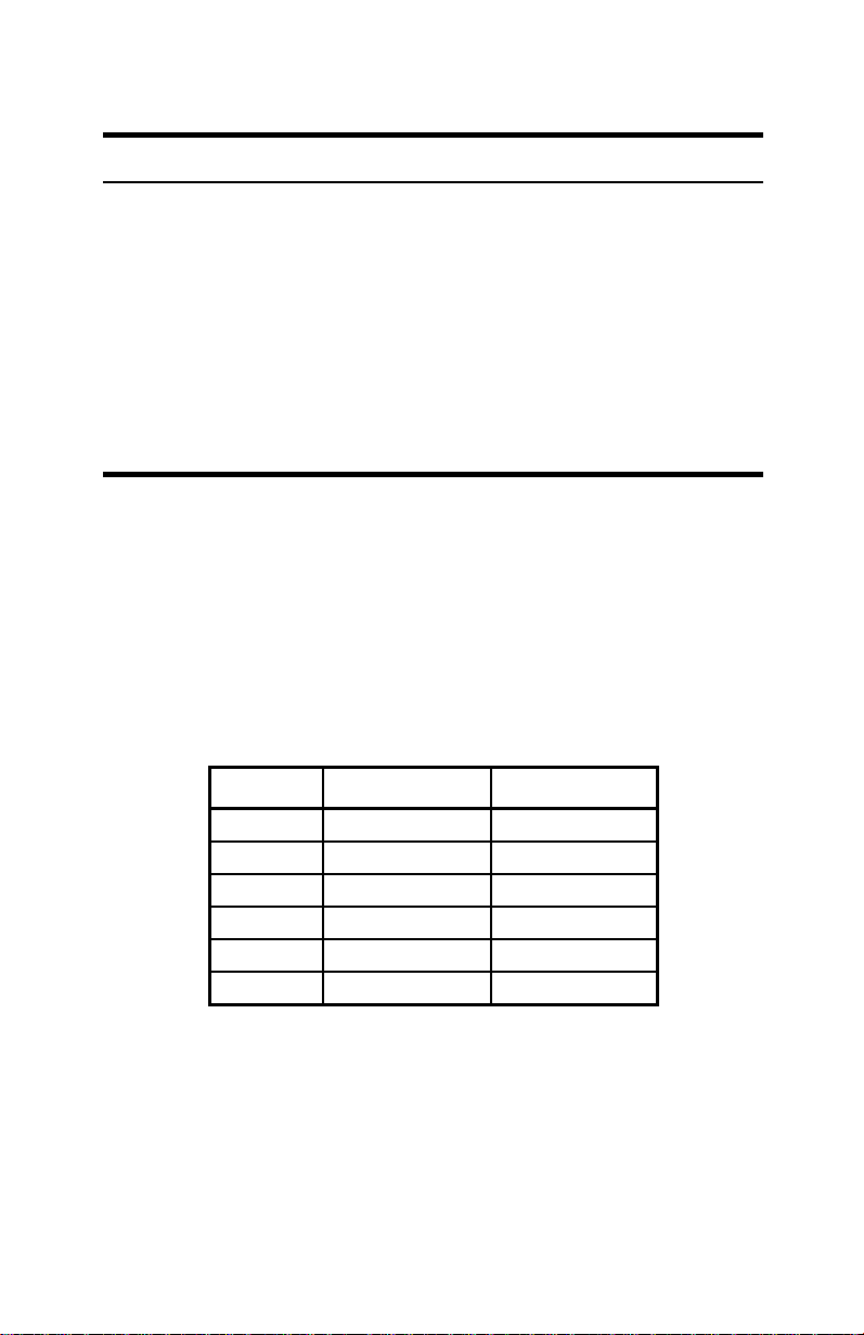
Table 1. System Board Jumper Settings
Description Jumper Setting Options
CPU Configuration J1F1-C, D See “Setting Microprocessor Jumpers”
CMOS Clear J1F1-A Pins 4&5: Normal
Pins 5&6: Clear
Password Clear J1F1-A Pins 1&2: Password enabled*
Pins 2&3: Password clear/disabled
CMOS Setup
Access
Processor
Voltage**
** Consult the documentation that came with your CPU
J1F1-B Pins 1&2: Enable System Setup*
Pins 2&3: Disable System Setup
J1F1-B Pins 4&5: Standard Voltage (3.3V)
Pins 5&6: VRE (3.6 V)
* Default setting.
for voltage requirements
Setting Microprocessor Jumpers
The configuration of the microprocessor-related jumpers varies
with the system’s microprocessor speed. Table 2 shows the
default settings for the system board jumpers.
Table 2. Microprocessor Speed Jumpers
CPU Freq. J1F1-C Settings J1F1-D Settings
200 1&2, 5&6 1&2, 5&6
180 2&3, 4&5 1&2, 5&6
166 1&2, 5&6 2&3, 5&6
150 2&3, 4&5 2&3, 5&6
133 1&2, 5&6 2&3, 4&5
120 2&3, 4&5 2&3, 4&5
*
42 Advantage! 9000 Series User’s Manual
Page 50

System Setup
System Setup is a program that configures your computer and
saves the configuration in battery-maintained memory.
Ordinarily, you do not need to use this program. However, you
may wish to run System Setup to set the date or time, to establish
a password, or to alter the settings for other features. You may
need to run the program to configure a newly installed piece of
hardware.
The computer includes security features, such as password
creation, port locking, and screen blanking. These are
configured in System Setup.
Starting System Setup
Turn the computer on. The computer will display the following
message as it starts:
To run System Setup, press <F1> now.
To start System Setup, press <F1> while the message is on
screen. If you do nothing, the computer bypasses System Setup
and continues its start-up routine.
You can deny users access to the System Setup program
by setting jumper block J1F1-B on the system board. See
“Setting the Password Jumper” on page 54 for more
information.
For the location of the jumper, see the illustration in the back of
this manual.
Using System Setup
When you start System Setup, the Main Menu appears. From
the Main Menu you can:
•
Set the date and time.
•
View your current hardware configuration
•
Access a secondary menu, such as Floppy or Boot.
Configuring Your Computer 43
Page 51

•
Initiate a BIOS update.
•
Exit System Setup.
The System Setup screen is divided into two parts.
The left part of the screen displays the menus and fields you use
to run the program. Generally, you select one of the secondary
menus listed under the words Advanced Options on the Main
Menu. The secondary menu contains a list of fields. Move the
cursor to a field and select a value for it. (The Date and Time
fields, however, are available directly from the Main Menu.)
The right part of the screen tells you how to use the secondary
menus and fields you select. This information changes
automatically as you make new selections.
Use the following keys in the System Setup program:
•
<Down arrow> or <Tab> moves the cursor forward to a
secondary menu or the next field.
•
<Up arrow> or <Shift+Tab> moves the cursor backward
to a secondary menu or the previous field.
•
<Enter> selects a secondary menu – causes it to display a
list of fields.
•
<Left arrow> and <Right arrow> move the cursor
between options in a field.
System Setup Fields
The following descriptions of the System Setup fields are
organized by the secondary menus under which the fields
appear.
Some fields are for reference only (you cannot enter new values
in them). Some fields may not appear at all, depending upon
your computer model.
44 Advantage! 9000 Series User’s Manual
Page 52

Main Menu
System Date: Use two-digit numbers to indicate month, day,
and year.
System Time: Use two-digit numbers to indicate hour, minute,
and second. Use a 24-hour clock.
Floppy Options
Press <Enter> to view or change the configuration of the floppy
drives.
Floppy A: Indicates whether floppy A is installed. This
field is for reference only.
Floppy B: Indicates whether floppy B is installed. This
field is for reference only.
Floppy A Type: This field specifies the type of the first
floppy drive, if installed. To select the floppy A type,
highlight the field and press <Enter>. Scroll up or down
through the selections in the dialog box using the
direction arrows. Press <Enter> to make your selection.
The options are None, 360 KB (5.25-inch), 1.2 MB (5.25-
inch), 720 KB (3.5-inch), 1.44/1.25 MB (3.5-inch), or
Disabled.
Floppy B Type: This field specifies the type of the second
floppy drive, if installed. To select the floppy B type,
highlight the field and press <Enter>. Scroll up or down
through the selections in the dialog box using the
direction arrows. Press <Enter> to make your selection.
The options are the same as those for Floppy A.
Floppy Access: Allows you to set the floppy drives to
either read/write or read only. The default is read/write.
Primary IDE Master, Primary IDE Slave, Secondary IDE
Master, and Secondary IDE Slave:
These fields report if an IDE device is connected to the system.
When selected, each of these fields brings up an identical
secondary menu for configuring the IDE device, as described
below.
Configuring Your Computer 45
Page 53

As described on the last page in your Zip drive
, the Zip drive’s IDE Device configuration must be
Guide
Disabled
set to
the configuration) or your system may hang. Your Zip
drive will be detected and configured when you start
Windows 95. If you enter System Setup and use the
option to return to default values, be sure to reset or
check that the field for the Zip drive is set to
See the Zip drive
the drive in Windows 95 DOS mode.
(which will allow Windows 95 to perform
User’s Guide
for information on using
User’s
Disabled
.
IDE Device Configuration: In this field, you specify
whether the system will automatically configure your
IDE device, or whether you intend to manually enter the
information. The options are Auto Configured, User
Definable, or Disabled.
If you choose the Auto Configured option, the Number of
Cylinders, Number of Heads, Number of Sectors, and
Maximum Capacity fields are automatically calculated by
the BIOS; no input is necessary or possible. These fields
will be for reference only.
If you choose the User Definable option, you will need to
know how many cylinders, heads, and sectors to specify
for your IDE device. Refer to the documentation that
came with your IDE device for this information.
Set this field to Disabled for any unused IDE connectors.
Notes on Drive Configurations:
If you are configuring your system to use only SCSI or
other non-IDE drive(s) connected to an add-in board, they
will be installed by the BIOS on the add-in board. Do not
attempt to install these drives through this Setup
program. Select
installed.
Do not set up a second hard-disk type unless you also
have set up a first hard-disk type.
If a CD-ROM drive is attached to the secondary IDE
connector, its drive type is
Attach an IDE hard drive to the IDE 2 connector
two IDE devices already use the IDE 1 connector. Do not
46 Advantage! 9000 Series User’s Manual
Disabled
if you have no IDE drives
Auto.
only
if
Page 54

set up a second hard-disk type unless you also have set
up a first hard-disk type.
Do not change the settings for the hard drive that came
with your computer.
Boot Options
Press <Enter> to view the boot options:
First Boot Device: Tells the system which device to first
check to find an operating system to boot from. The
options are Disabled, Floppy, Hard Disk, CD-ROM, and
Network.
Second Boot Device: Tells the system which device to
boot from if the first boot device fails. The options are:
Disabled, Floppy, Hard Disk, and Network.
Third Boot Device: Tells the system which device to boot
from if the first two devices fail. The options are:
Disabled, Floppy, Hard Disk, and Network.
Fourth Boot Device: Tells the system which device to
boot from if all three of the other devices fail. The options
are: Disabled, Floppy, Hard Disk, and Network.
Num Lock: Select this field to make the Num Lock
feature either active or inactive when the system starts.
Choose On to activate the feature or Off to deactivate it.
(Default is Off.)
Video Mode: Displays the video type. This field is for reference
only.
Mouse: Reports whether the mouse is active when the
computer starts. This field is for reference only.
Base Memory: Reports the amount of base (DOS) memory
available. This field is for reference only.
Extended Memory: Reports the amount of extended memory
available. This field is for reference only.
BIOS Version: Displays the version number of the installed
BIOS. This field is for reference only.
Configuring Your Computer 47
Page 55

Advanced Menu
Processor Type: Displays the name/type of processor installed.
This field is for reference only.
Processor Speed: Displays the speed of processor installed.
This field is for reference only.
Cache Size: This field is visible only if a secondary cache
memory module is installed. This field is for reference only.
Peripheral Configuration
Press <Enter> for the secondary menu.
Primary IDE Interface: Use this option to enable or
disable the onboard primary IDE controller. You would
want to disable this controller if you were installing a
board with an IDE or SCSI controller on it.
Secondary IDE Interface: Use this option to enable or
disable the onboard secondary IDE controller. You would
want to disable this controller if you were installing a
board with an IDE or SCSI controller on it.
Floppy Interface: Use this option to enable or disable the
onboard floppy device. You would want to disable this
controller if you were installing a board with a floppy
controller on it.
Serial Port 1 Address: Use this option to assign a serial
port address to port 1. The following options are
available:
Disabled
COM1, 3F8, IRQ4 (Default)
COM2, 2F8, IRQ3
COM4, 2E8, IRQ 3
COM1, 3F8, IRQ3
COM2, 2F8, IRQ4
COM4, 2E8, IRQ4
Auto
48 Advantage! 9000 Series User’s Manual
Page 56

Serial Port 2 Address: Use this option to assign a serial
port address to port 2. The following options are
available:
Disabled
COM2, 2F8, IRQ4
COM3, 3E8, IRQ3
COM4, 2E8, IRQ 4
COM2, 2F8, IRQ3
COM3, 3E8, IRQ4
COM4, 2E8, IRQ3
Auto
Serial Port 2 IR Mode: Enables/disables the onboard IR
controller, if your system came configured with the IrDA
(Infrared Data Association ) feature. If your computer did
not come with the IrDA feature, this field should always
be set to Disabled.
Your computer can support either serial port 2 or the
onboard IrDA controller, but not both at the same time. If
Serial Port 2 IR Mode is enabled, serial port 2 will be
automatically disabled. However, the BIOS field will not
be updated to reflect this.
If you are attaching an infrared device, such as a remote
control, to the serial port, DO NOT enable Serial Port 2 IR
Mode: this field is for the onboard IrDA controller ONLY.
If you enable Serial Port 2 IR Mode, you will actually be
disabling the serial port you are trying to attach to.
Parallel Port Address: Use this option to assign a parallel
port address. The following options are available:
Disabled
LPT3, 3BC, IRQ7
LPT1, 378, IRQ7
LPT2, 278, IRQ7 (Default)
LPT3, 3BC, IRQ5
LPT1, 378, IRQ5
LPT2, 278, IRQ5
Auto
Configuring Your Computer 49
Page 57

Parallel Port Mode: Select Compatible for standard AT-
mode, Bi-Directional for extended mode, ECP for
Extended Capability Port, or EPP for Enhanced Parallel
Port.
Audio Configuration
Press <Enter> to enter the secondary menu. The following fields
are available:
Configuration Mode: Tells the system whether you want
it to automatically configure your audio system (Auto
option), whether you intend to configure it yourself
(Manual option), or whether you want to disable the
audio system (Disabled option). If you choose Auto, the
other fields on this screen (except for Game Port) become
shaded out, and are for reference only.
SB Base Port Address: Can be set to 220h, 240h, or
Disabled.
WSS Base Port Address: Can be set to 530h, E80h, F40h,
604h, or Disabled.
MPU401 Base Port Address: Can be set to 330h, 332h,
334h, 300h, or Disabled.
WSS Interrupt: Can be set to IRQ 7, 9, 10 or 11, or
Disabled.
SB Play/MPU401 Interrupt: Can be set to IRQ 5, 7, 9, 10,
or Disabled.
WSS Play DMA: Can be set to Channel 0 or Disabled. If SB
Play/WSS Capture DMA is disabled, WSS Play DMA can
be set to channel 0, 1, or 3.
SB Play/WSS Capture DMA: Can be set to Channel 1 or
Disabled.
Game Port: Can be set to Auto, Enabled, or Disabled.
Game Port Status: Shows the current port address. This
field is for reference only.
FM Synthesizer Port Status: Shows the current port
address. This field is for reference only.
50 Advantage! 9000 Series User’s Manual
Page 58

Advanced Chipset Configuration
This screen shows the status of the memory banks. It detects
whether the banks are populated, and what mode (EDO or FPM)
the installed SIMMs are.
Power Management Configuration
Press <Enter> to enter the secondary menu.
IDE Drive Power Down: Use this option to enable IDE
power down during periods of no activity.
AST hard drives recognize when power-conservation is
enabled. Other drives, particularly ones that require an
add-in controller board, may not.
VESA Video Power Down: Use this field to enable VESA
power down during periods of no activity. The proper
setting is dependent upon the VESA mode(s) supprted by
your monitor. Consult your monitor doccumentation for
more details. Options are: Disabled, Standby, Suspend, and
Sleep.
Inactivity Timer (Minutes): Use this option to specify the
number of minutes of inactivity before power
management is activated. The acceptable range is 1-255.
To deactivate this feature, set the value to 0.
Plug and Play Configuration
Boot With PnP OS: Enables the PC to boot with an
operating system capable of managing Plug and Play
add-in cards. The options are None, Other, and
Windows 95.
Security Menu
User Password is: Reports whether a User password is enabled.
This field is for reference only.
Set User Password: Use this option to specify, change, or delete
the password. For more information on passwords, see “Using
Passwords” on page 52.
Configuring Your Computer 51
Page 59

Exiting System Setup
To exit System Setup, go to the Exit menu. Choose from one of
the options below:
Exit Saving Changes: Saves the new values you have
entered in System Setup and exits the setup program.
Exit Discarding Changes: Cancels any new values
entered and exits the setup program.
Load Setup Defaults: Resets all of the setup options to
their defaults.
Discard Changes: Restores the values in System Setup to
their previously saved state. This undoes any changes
you may have made to System Setup.
Using Passwords
A password prevents an unauthorized person from using the
computer.
Creating or Changing a Password
To create a user password, use System Setup:
From the Main Menu, select Security.
1.
Move the cursor to the Set User Password field.
2.
Select Enable. Then press <Enter>.
3.
The cursor moves to the Enter the Password field. Type the
4.
password you want to use. No characters appear on
screen as you type, so that other people cannot see the
password.
As you type, follow these rules:
5.
•
Create a password of one to seven characters. If you
type more than seven keystrokes and press <Enter>,
the computer beeps, and you must reenter the
password. Use any combination of letters and
numbers.
52 Advantage! 9000 Series User’s Manual
Page 60

•
The system distinguishes between numeric keys above
the letter keys and those in the numeric keypad at the
right of the keyboard. For instance, if you enter a
keypad 8 when enabling the password, you may not
enter the 8 above the letter keys to use the password.
•
The system does not distinguish between uppercase
and lowercase letters in a password. For instance, D is
the same as d.
•
If you press an invalid key, the computer beeps, and
you must reenter the password.
•
If you make a mistake, use <Backspace> to erase the
characters up to the mistake, then retype the correct
characters.
•
You cannot leave the Enter the Password field without
establishing a password. If you begin to create a
password and decide you do not want to use it, finish
creating it and then cancel it. See the next section,
“Canceling a Password.”
When you finish typing, press <Enter>. The cursor
6.
moves to the Verify field. Reenter the password and press
<Enter>.
If the passwords match exactly, the password is enabled. If not,
the computer beeps. Press <Enter> again and repeat the
process.
To change a password, cancel the existing password and then
create a new one. See the next section, “Canceling a Password.”
Canceling a Password
To cancel a password, use System Setup or turn off the password
jumper on the system board. To use System Setup:
From the Main Menu, select Security.
1.
Move the cursor to the Set User Password field.
2.
Use the left or right arrow key to select None. Then press
3.
<Enter>. The password is canceled.
Configuring Your Computer 53
Page 61

Setting the Password Jumper
The password jumper allows you to disable the passwords
entered in System Setup.To set the password jumper:
Turn off the computer and open the system cover
1.
(see“Removing the System Cover”).
Altering jumper settings while the computer is on can
permanently damage the computer and its components.
To avoid accidental discharge of static electricity as you
handle components or jumpers, use a grounding wrist
strap. Static electricity can damage computer
components.
Locate jumper block J1F1-A (see “Jumper Settings” on
2.
page 41 for an illustration of this jumper).
Move the jumper from pins 1 and 2 to pins 2 and 3.
3.
Turn the computer on again.
4.
After the BIOS messages appear, turn the system off.
5.
Move the jumper back from pins 2 and 3 to pins 1 and 2.
6.
Close the system cover and restart the computer. Once
you have cleared the password, you can create a new one.
Refer to the section “Set User Password” for directions on
how to create a user password.
Updating the System BIOS
Your computer uses flash BIOS, which enables you to update the
BIOS easily from a floppy disk. If AST releases a BIOS update
for your computer, contact your AST reseller to obtain a copy of
the BIOS update disk. Or, if you have a modem, copy the
necessary files from the AST On-Line BBS or Website onto a
high-density floppy disk. See the customer-service reference
that accompanied your computer for connecting online to AST.
It is rare, though possible, for the flash BIOS contents to become
corrupted, causing certain configuration parameters to be lost.
If this occurs, the following message appears on your screen:
54 Advantage! 9000 Series User’s Manual
Page 62

“Personality Identification Data has been
lost. Contact AST Technical Support.”
If this occurs, your system will still operate, but less efficiently.
Contact your local AST Technical Support.
Performing the BIOS Update
To perform the BIOS update:
Turn off the computer.
1.
Place the BIOS Update disk in drive A. If you have
2.
downloaded the BIOS file from a BBS, you need to make
sure that you have copied the file to a bootable, system
disk.
Turn the computer back on. A title screen should appear,
3.
with the words “FLASH Memory Update Utility.”
Follow the prompts on the screen to install the new BIOS.
4.
If the update is completed successfully, the program will
inform you of this fact. Proceed to step 4. If the program
indicates that the BIOS did not install successfully, refer to
the next section, “Troubleshooting the BIOS Update” on
page 55 for more information.
Remove the BIOS Update disk from drive A and press
5.
<Enter>. The program will end, and the computer will
begin its normal boot-up sequence. When prompted,
press <Ctrl+Alt+Esc> to access System Setup. Verify
your configuration by reading the BIOS version field of
the Main menu.
Once you have verified your configuration, reboot your
6.
system to use the new BIOS.
Troubleshooting the BIOS Update
If the FLASH BIOS Update Utility indicates that the BIOS
upgrade was unsuccessful, make sure that:
•
You have the correct BIOS update disk for your machine.
•
The system battery does not need to be replaced. If you
have received low-battery warnings, replace the system
Configuring Your Computer 55
Page 63

battery (see “Replacing the Computer Battery” on page
58).
Retry the BIOS update. If the problem persists, contact your
AST reseller.
56 Advantage! 9000 Series User’s Manual
Page 64

Troubleshooting
If your computer does not start, check the following:
•
Are all the cables properly connected to the computer?
(See “Connecting a Monitor” on page 5 and subsequent
sections.)
•
If you have installed an add-in board, have you installed
it correctly? (See “Installing Add-in Boards” on page 21.)
•
Is the voltage setting on the back panel set to 115 V, or
230 V if your power outlet uses that voltage? (See
“Connecting the Power Cord” on page 8.)
If the computer starts, but nothing appears on the screen, check
the following:
•
Is the monitor cable attached to the monitor port on the
back of the computer? Is the monitor turned on? Are th e
brightness and contrast controls correctly adjusted?
Check your monitor manual.
•
Is your software correctly configured for your monitor
and video adapter? Check the software user’s manual.
•
If you installed an add-in video board, have you installed
and configured it correctly?
If the computer comes on, but does not finish booting, check the
following:
•
Are the Num Lock, Caps Lock, and Scroll Lock lights
flashing? If so, type the user password (see “Using
Passwords” on page 52).
•
Does the computer beep more than once when you turn
it on? The computer might not be configured correctly.
Run System Setup to fix the configuration (see
“Configuring Your Computer” on page 41).
If the computer still beeps more than once, your
computer may have a malfunction. Contact your AST
reseller for assistance.
•
Does a configuration error message appear on the
screen? If so, run System Setup to correct the problem
(see “Configuring Your Computer” on page 41).
Troubleshooting 57
Page 65

•
Does the computer report a CMOS or battery failure
error? Run System Setup to check your configuration. If
the configuration settings are lost, the computer battery
has run out and needs to be replaced (see “Replacing the
Computer Battery” on page 58).
As you use the CD-ROM drive, you may encounter one of three
errors:
•
A Windows “Invalid Path” dialogue box presents the
message, “The working directory is invalid.” In this
case, there is no CD in the drive. Press <Esc>, insert the
correct CD, and double-click the icon again.
•
A Windows “Application Execution Error” dialogue box
appears on the screen. The wrong CD is in the drive.
Press <Esc>, insert the correct CD, and double-click the
icon again.
•
No error message appears but the program does not run.
Insert the correct CD and run the program again.
If the computer boots but your printer does not print, make sure
the printer is properly connected and turned on. Most printers
require that you install printer driver software from a floppy
disk before the printer works correctly with the computer. (See
the manual for the device for instructions.)
If the computer boots but does not run properly, is the compute r
unable to use the hard disk you installed? Make sure it is
configured in System Setup (see “Configuring Your Computer”
on page 41). Also, make sure you have partitioned and
formatted the drive (See your Windows 95 documentation).
Replacing the Computer Battery
If the computer reports a CMOS or battery failure error, you
may need to replace the battery. Run System Setup to check
your configuration settings. If the settings are lost, replace the
battery.
To replace the battery:
58 Advantage! 9000 Series User’s Manual
Page 66

Turn off the computer, unplug the power cord, and
1.
disconnect any peripheral devices. Remove the cover (see
“Removing the System Cover” on page 19).
Locate the battery socket (see the illustration in the back
2.
of this manual).
Remove any add-in boards that prevent you from
3.
reaching the battery.
Remove the old battery by holding it by its me tal rim and
4.
pulling it out of the socket. (Pull on the battery, not the
socket.)
Insert the new battery into the socket with the “+” side
5.
facing up. Press down on the battery until it snaps into
place.
Replace the battery with AST part number 175000-015
(3.3-V) only. Use of other batteries may present a risk of
fire or explosion.
Batteries may explode if mishandled. Do not recharge,
disassemble, heat above 100 C, incinerate, or expose
contents to water.
Batteries contain hazardous material and should be
recycled. In some cases, it is illegal to dispose of these
batteries as solid waste. Make sure you follow all state
and local regulations. If you want, send used batteries to
the following address:
AST Computer
1001 N.E. Loop 820 Dock 5
Fort Worth, TX 76131
Attn. Safety Department
Replace any add-in boards you removed. Replace the
6.
system cover. Reconnect peripheral devices and plug in
the power cord. Turn on the system.
Run System Setup to configure the system (see
7.
“Configuring Your Computer” on page 41).
Troubleshooting 59
Page 67

Abbreviations
The following abbreviations are used in this manual:
APM. . . . . . .Advanced power management
BIOS . . . . . .Basic input/output system
BBS . . . . . . .Bulletin board system
CD-ROM . .Compact disc, read-only memory
CGA. . . . . . .Color graphics adapter
CMOS . . . . .Complementary metal-oxide semiconductor
DMA . . . . . .Direct memory access
DPMS . . . . .Display power-management signaling
DOS. . . . . . .Disk operating system
DRAM. . . . .Dynamic random-access memory
ECP . . . . . . .Extended Capabilities Port
EGA . . . . . . .Enhanced graphics adapter
EPP. . . . . . . .Enhanced Parallel Port
EPROM . . .Erasable programmable read-only memory
Hz. . . . . . . . .Hertz
I/O . . . . . . . .Input/output
IDE. . . . . . . .Integrated drive electronics
IrDA. . . . . . .Infrared Data Association
IRQ . . . . . . .Interrupt request
ISA. . . . . . . .Industry standard architecture
KB . . . . . . . .Kilobyte
MB . . . . . . . .Megabyte
MDA . . . . . .Monochrome display adapter
MHz. . . . . . .Megahertz
PCI . . . . . . . .Peripheral Connect Interconnect
PnP. . . . . . . .Plug and Play
POST . . . . . .Power-on self test
PS/2 . . . . . . .Personal System/2
RAM . . . . . .Random-access memory
SIMM . . . . .Single in-line memory module
®
60 Advantage! 9000 Series User’s Manual
Page 68

VGA. . . . . . .Video graphics array
ZIF . . . . . . . .Zero-insertion force
Abbreviations 61
Page 69

Glossary
AUTOEXEC.BAT file
A DOS file on your boot disk that contains commands
carried out automatically whenever you start the computer.
Base I/O address
The memory location that the computer uses to
communicate with a device attached to it. Unless otherwise
specified, each device installed in or attached to the
computer uses its own unique I/O address.
BIOS (basic input/output system)
Software (independent of any operating system) built into
the computer that communicates with the screen, keyboard,
and other peripheral devices.
Boot
The computer’s starting process. You can start the computer
with either of the following methods:
•
•
Cold boot: If you turn the computer on or press the reset
button, the computer clears out RAM, resets, runs
through all computer self-tests, and loads the
AUTOEXEC.BAT and CONFIG.SYS files.
Warm boot: If you press <Ctrl+Alt+Del> while the
computer is on, the computer clears out RAM only.
Boot disk
A disk containing programs required to start your
computer. A boot disk can be a floppy disk or hard disk.
Built-in VGA (video graphics array)
The video display adapter that is built into the system
board. This adapter is compatible with software that runs in
VGA, a high-resolution video standard. You do not need to
install a separate video display adapter if you are using a
VGA-compatible monitor.
62 Advantage! 9000 Series User’s Manual
Page 70

Bus
A communication channel carrying signals from any device
used by the system to another device. For example, data
being transferred to and from a hard disk travels on a bus.
Byte
The basic unit of measure for computer memory. A
character, such as a letter of the alphabet, uses one byte of
memory. Computer memory is often measured in kilobytes
or megabytes. Each byte is made up of eight bits.
Check box
An element of a dialog box. A check box is either filled or
left blank, indicating a yes-or-no decision.
Click
To press the left mouse button and then release it.
CD-ROM (compact disc read-only memory)
A disk, which is similar in appearance to an audio compact
disc, that can store large amounts of data, video, and sound.
Data can be read from, but not written to, a CD-ROM.
CMOS (complementary metal-oxide semiconductor) memory
The memory that stores the configuration you establish by
running the computer’s setup program. CMOS memory
uses very little power and stores the configuration
information even when the computer is turned off.
Command
A word or series of words you use to initiate an operating
system action.
Command line
The commands and their parameters that you type at the
(MS-DOS) command prompt of an operating system.
Command prompt
A character or string of characters that indicate the
beginning of the operating system command line.
CONFIG.SYS file
A file on the boot disk that configures MS-DOS. The
commands in a CONFIG.SYS file (if one exists on your boot
Glossary 63
Page 71

disk) are carried out before those in an AUTOEXEC.BAT
file. Usually, the commands load device drivers, which are
files that enable the computer to use specialized hardware
and software.
Configuration file
A file that contains resource assignment options for a
particular board. The configuration management software
uses this information to configure the board.
Current directory
The directory in which you are currently working.
Cursor
A flashing character that indicates where the text that you
type will appear on the screen.
Dialog box
A temporary window that asks you for information or a
decision before it executes a command
Default
For hardware, the way a switch or jumper is set at the
factory. For software, the value of a parameter unless you
specify otherwise.
Device driver
A program that controls how software communicates with
a physical device (e.g., a mouse, memory, or a printer).
Directory
A group of files on a disk. A directory can also contain other
directories.
Disk
The device used by the computer to store and retrieve
information. Disk can refer to a floppy disk or hard disk.
Display adapter
Computer circuitry that produces video images on the
monitor. Your computer includes built-in VGA, a display
adapter that is built into the system board. You can also
install an add-in video board, a display adapter on a
separate plug-in board.
64 Advantage! 9000 Series User’s Manual
Page 72

DMA (direct memory access)
The process of transferring data directly between memory
and peripheral devices without microprocessor
intervention.
Double click
Press twice, in rapid succession, on a mouse button.
DPMS (data power-management signaling)
Describes monitors that can conserve power when the
system is inactive by blanking the screen.
Drag
To press and hold down the left mouse button when the
mouse pointer is positioned over an object, and then move
the mouse to a new position and release the mouse button.
The object moves along with the mouse pointer to the new
position.
Drive
A hierarchical organization of directories, stored on a disk.
A drive usually corresponds to the medium stored in a
specific physical storage device, such as a floppy disk in a
disk drive. See directory, directory tree, subdirectory.
Driver
See Device driver.
ECP (extended capabilities port)
A parallel port that supports bi-directional and DMA data
transfer.
EPP (enhanced parallel port)
A parallel port that supports high-speed, bidirectional data
transfer.
Extended memory
System memory above 1 MB that can be accessed directly by
some operating systems.
FDISK
A DOS utility program that enables you to create partitions,
which DOS can recognize as a drive, on a hard disk. FDISK
Glossary 65
Page 73

can turn an entire hard disk into a single partition or divide
a hard disk into smaller partitions.
File
A collection of information that has been stored in an
operating system file system.
Filename
The name of a file. A filename has two parts that are
separated by a period. To the left of the period is the name
of the file, which can contain one to eight characters, and to
the right of the period is the extension. The filename usually
describes the contents of the file. See extension.
Floppy disk
A removable disk, also called “floppy” or “diskette.” Data
written to a floppy disk remains until it is overwritten or
erased.
Hard disk
A large-capacity data-storage device that is installed inside
the computer. Data written to the hard disk remains unt il it
is overwritten or erased.
IDE (integrated drive electronics) hard drive
A hard drive with a built-in controller. You can install an
IDE drive without installing a separate controller board,
thereby freeing an expansion slot for other uses.
I/O (input/output)
Describes the transfer of data to and from the computer –
primarily between the computer and peripheral devices
such as printers.
ISA (industry standard architecture) expansion slot
An expansion slot that is designed for 8- or 16-bit ISA addin boards. The ISA expansion bus operates at 8 MHz.
KB (kilobyte)
1,024 bytes. For example, 8 KB is shorthand for 8,192 bytes.
Local bus
A bus that connects peripheral devices directly to the
microprocessor. The bus usually runs at the external clock
66 Advantage! 9000 Series User’s Manual
Page 74

rate of the microprocessor and can transfer at one time the
maximum number of bits supported by the microprocessor
and peripheral devices (for example, 32 bits).
MB (megabyte)
1,024 kilobytes or 1,048,576 bytes. For example, 16 MB is
16,384 KB or 16,777,216 bytes.
Menu bar
The horizontal stripe across the top of a window containing
the names of an application program’s menus.
MHz (megahertz)
A measure of frequency that equals a million cycles per
second. The speed of the microprocessor is measured in
MHz.
ns (nanosecond)
A measure of speed that equals a billionth of a second. The
speed at which memory and other chips communicate with
the system is measured in ns.
Parameter
Information that you need to provide before MS-DOS can
execute a command.
Partition
A portion of a hard disk that DOS recognizes as an
individual drive. For example, you can divide an 80-MB
hard disk into two 40-MB partitions that DOS would
identify as drives C and D.
PCI (peripheral component interconnect)
A 32-bit local bus that provides connections for 32-bit +5-V
add-in boards and on-board video. The bus operates at the
external clock speed of the microprocessor (up to 33 MHz).
PCI devices are configured automatically by the system.
Plug and Play boards
Boards that comply with the Plug and Play specification.
Such boards are configured automatically when the system
starts.
Glossary 67
Page 75

POST (power-on self-test)
A test performed by the computer whenever you turn on the
power or press the reset button. POST checks system
integrity.
RAM (random-access memory)
A portion of the computer system’s memory that is
designed as a temporary storage area for data and
programs. RAM includes conventional and extended
memory. You can write to and read from RAM.
Information stored in RAM is erased when the system is
turned off. To preserve your data, you need to save it to a
disk.
ROM (read-only memory)
Permanent computer memory dedicated to a particular
function. For example, the instructions for starting the
computer when you first turn on power are contained in
ROM. You cannot write to ROM. (ROM is not the same as
random-access memory).
Root directory
The main directory in a drive.
SIMM (single inline memory module)
A small circuit board with memory chips.
Window
A rectangular area on you screen in which you view an
application program or a file.
68 Advantage! 9000 Series User’s Manual
Page 76

Appendix A: Regulatory Information
FCC Class-B Warning
This computer generates and uses radio-frequency energy. If
not installed and used properly, the computer may interfere
with radio or television reception. The computer has been tested
and certified to comply with the limits for a class-B digital
device, as defined in part 15 of the FCC rules. Class-B limits are
designed to provide reasonable protection against radio/
television interference in a residence. To comply with FCC
regulations, you must use shielded cables with this computer.
Operation with unapproved equipment or unshielded cables is
likely to result in interference with radio or television reception.
Changes made to this computer without the approval of AST
Research could void your authority to operate the computer.
The computer may cause interference even though it meets
class-B limits. (As a test, turn the computer off and on, and
gauge the effect on an operating radio or television.) If there is
interference, try to eliminate it by:
•
Reorienting or relocating the receiving antenna of the
radio or television.
•
Increasing the distance between the computer and
receiver.
•
Connecting the computer to an outlet on a circuit
different from that to which the receiver is connected.
•
Consulting your authorized AST reseller or an
experienced radio/television technician for help.
DOC Notice
This digital apparatus does not exceed the Class B limits for
radio noise emissions from digital apparatus as set out in the
interference-causing equipment standard entitled “Digital
Apparatus”, ICES-003 of the Department of Communications.
Appendix A: Regulatory Information 69
Page 77

Cet appareil numérique respecte les limites de bruits
radioélectriques applicables aux appareils numériques de
Classe B prescrites dans la norme sur le matérial brouilleur:
“Appareils Numériques”, NMB-003 édictée par le ministre des
Communications.
Warning
Replace the battery with an AST battery part number 175000015, contact your authorized AST reseller for a replacement. Use
of another battery may present a risk of fire or explosion. Do not
disassemble, heat above 100 C or incinerate. Make sure that you
follow all state and local requirements when you dispose of the
old battery.
Avertissement
Ne remplacez la batterie que par un modèle AST 175000-015,
commandez-en un autre à votre revendeur agréé AST. L’emploi
de tout autre modèle présente des risques d’incendie ou
d’explosion. Ne démontez pas la batterie, ne portez pas sa
température au-dessus de 100 C et ne l’incinérez pas. Pour vous
débarrasser d’une batterie usagée, veillez à respecter tous les
règlements nationaux et locaux en vigueur.
Advarsel
Eksplosjonsfare ved fellektig skifte av batteri. Benytt samme
batteritype eller en tilsvarande type anbefalt av
apparatfabrikanten. Brukte batterierr kasseres i hanhold til
fabrikantans instruksjoner.
70 Advantage! 9000 Series User’s Manual
Page 78

CE Compliance
CE marked AST computers comply with the following
standards:
Electromagnetic Compatibility – Application of Directives: 89/
336/EEC, 92/31/EEC, 93/68/EEC
Emissions – EN 55022 (1987) Performance criteria: Class B
Immunity – EN 50082-1 (1992) subset:
IEC 801-2 (1991) – CD Level 2 (4 kV), AD Level 3
(8 kV) Performance criteria: Level 2
IEC 801-3 (1984) – Level 2 (3 V/m, 80% AM
modulation w/ 1 kHz signal) Performance
criteria: Level 1
IEC 801-4 (1988) – Level 2 (1 kV AC power input,
0.5 kV I/O lines) Performance criteria: Level 2
Product safety – Application of Directives: 73/23/EEC. 93/68/
EEC
Safety of ITE – EN 60950 (1992) and amendments 1 and 2
Manufacturer: AST Research Incorporated (AST Computer)
16215 Alton Parkway
Irvine, CA 92718 USA
Signed Declaration of Conformity documents for AST products
are on file at the AST Ireland facility.
European Address: AST Ireland Limited
National Technology Park
Plassey
Limerick
Ireland
This product contains a Class 1 laser product with a Class 1 laser
source employing a laser diode that emits invisible laser
radiation at 5mW. The wavelength of the laser radiation is 760800nm.
Appendix A: Regulatory Information 71
Page 79

CLASS 1 LASER PRODUCT
CAUTION
The laser beam used by this CD-ROM drive unit can be harmful
to the eyes. Do not attempt to open the unit. All service
procedures should be performed by an authorized dealer or
distributor.
WARNING
Never use any optical instruments in conjunction with this unit.
To do so will greatly increase the hazard to your eyes.
ADVARSEL
USYNLIG LASERSTRÅLING VED ÅBNING, NÅR
SIKKERHEDSAFBRYDERE ER UDE AF FUNKTION. SE IKKE
IND I STRÅLEN - HELLER IKKE MED OPTISKE
INSTRUMENTER.
ADVARSEL
USYNLIG LASERSTRÅLING NÅR DEKSEL ÅPNES OG
SIKKERHEDSLÅS BRYTES. STIRR IKKE INN I STRÅLEN
ELLER SE DIREKTE MED OPTISKE INSTRUMENTER.
LUOKAN 1 LASERLAITE
VAROITUS
LAITTEEN KÄYTTÄMINEN MUULLA KUIN TÄSSÄ
KÄYTTöOHJEESSA MAINITULLA TAVALLA SAATTAA
ALTISTAA KÄYTTÄJÄN TURVALLISUUSLUOKAN 1
YLITTÄVÄLLE NÄKYMÄTTöMÄLLE LASERSÄTEILYLLE.
72 Advantage! 9000 Series User’s Manual
Page 80

KLASS 1 LASERAPPARAT
VARNING
OM APPARATEN ANVÄNDS PÅ ANNAT SÄTT ÄN I
DENNA BRUKSANVISNING SPECIFICERATS, KAN
ANVÄNDAREN UTSÄTTAS FöR OSYNLIG LASERSTRÅLNING, SOM öVERSKRIDER GRÄNSEN FöR
LASERKLASS 1.
Labels appearing on the drives:
CAUTION - INVISIBLE LASER RADIATION WHEN OPEN.
AVOID EXPOSURE TO BEAM.
VORSICHT! UNSICHTBARE LASERSTRAHLUNG TRITT
AUS, WENN DECKEL GEöFFNET. NICHT DEM STRAHL
AUSSETZEN!
VARNING - OSYNLIG LASERSTRÅLNING NÄR DENNA
DEL ÄR öPPNAD. STRÅLEN ÄR FARLIG.
ADVARSEL - USYNLIG LASERSTRÅLING VED ÅBNING.
UNDGÅ UDS/ETTELSE FOR STRÅLING.
CLASS 1 LASER PRODUCT LASERSCHUTZKLASSE 1
PRODUKT TO EN 60825
Appendix A: Regulatory Information 73
Page 81

74 Advantage! 9000 Series User’s Manual
Page 82

Index
A
Abbreviations
60
listed
Add-in boards
configuring after installing
installing
PCI
21
18
B
Battery
replacing
safety warning
troubleshooting during flash
BIOS update
BIOS
downloading flash
flash, described
performing update
updating
BIOS update
troubleshooting
Boot
cold
options in System Setup
warm
Bottom panel
removing, illustrated
58
59
55
2
54
55
17
17
C
CD-ROM
laser beam caution
16
using
Chassis
removing bottom panel
Clip, grounding
Computer
clearances
configuring
3
28
41
54
55
16
features
restarting
setting up
turning on
25
unpacking
1
16
5
8
2
D
Date
setting
Disks
using
DPMS
SVGA monitor
Drive bay
front
locations, illustrated
rear
removing rear
removing rear panel
Drives
CD-ROM type on secondary
configuring power conserva-
47
22
installing
installing in front bay
installing in rear drive bay
locations
maximum number
preparations for installing
using floppy
45
13
5
26
26
32
46
25
25
1
13
IDE connector
tion in System Setup
26
32
51
27
32
27
F
21
FCC Class-B Warning
Floppy drive
cables, illustrated
connecting controller to
types supported
69
30
30
18
Index 75
Page 83

Front panel
removing, illustrated
G
Guide rails
29
attaching
installing, illustrated
I
IDE
device configuration
Installation
21
add-in boards
precautions
Introduction
18
1
J
Jumper block
defined
Jumpers
microprocessor, setting
setting
41
41
K
Keyboard
7
adjusting height of
connecting
safety
types of keys, illustrated
using
6
3
12
L
Lights
location of activity and status,
15
illustrated
M
Memory
34
adding system
battery-maintained
configurations
43
34
54
35
35
35
5
5
5
13
21
43
48
22
7
7
correct configuration
20
29
46
42
12
incorrect configuration
maximum
minimum and maximum
video, adding
Microprocessor
description
installing
upgrading
Monitor
connecting
connecting to video port
power management
safety
types supported
Mouse
cautions while using
connecting
using
1
39
1
37
37
5
3
6
13
P
Panel
removing bottom
Password
running System Setup
setting
Passwords
canceling
changing
creating
setting jumper
using
Peripheral devices
configuring in System Setup
connecting
Plug and Play
manual configuration for non-
Port
audio port location
parallel port location
51
53
53
52
52
6
compliant ISA boards
76 Advantage! 9000 Series User’s Manual
Page 84

peripheral port location
serial port location
Power
connector location, illustrated
conserving
Power Management
default time settings
when to disable
10
7
10
R
Regulatory Information
Riser card
21
defined
69
10
7
8
44
fields
43
45
43
43
main menu
overview
security menu
starting
using
51
T
Time
45
setting
Troubleshooting
computer does not start
printer
57
58
S
Safety
3
modem
option
static
Security
menu in System Setup
SIMMs
adding
compatibility
installing
installing, illustrated
removing
Slots, expansion
number of
Sound Cards
configuring
System board
illustrated
System configuration
System cover
removing
replacing
System Setup
advanced menu
auto configuration
exit menu
3
3
35
34
37
36
2
25
78
19
21
52
U
Upgrading
list of options
system memory
video memory
51
37
V
VESA Connector
Video
add-in adapter option
connecting a monitor
Video adapters
supported
18
34
34
24
5
5
18
Z
ZIF socket
Zip disks
using
Zip drive
41
48
50
setting configuration for
37
16
46
Index 77
Page 85
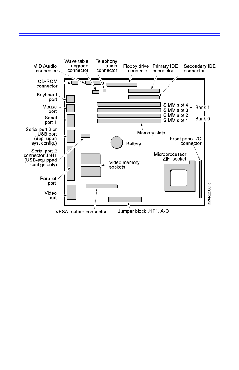
System Board
78 Advantage! 9000 Series User’s Manual
 Loading...