

Invivo WBT1 Users Manual

Invivo Corporation
PRECESS MRI PATIENT MONITORING SYSTEM
OPERATIONS MANUAL

NOTE
Notified body number 0413 is only relevant for the MDD 93/42/EEC Directive.

TABLE OF CONTENTS
Paragraph Number Page Number
Equipment Classification................................................................................................................. i
Precautions...................................................................................................................................... ii
User Responsibility...................................................................................................................... xvi
User Responsibility Precess MRI Patient Monitoring Accessories............................................ xvii
Part Number Precess MRI Patient Monitoring Accessories...................................................... xviii
1.0 INTRODUCTION. ........................................................................................................ 1-1
1.1 Product Description ......................................................................................................... 1-1
1.1.1 System Parameters............................................................................................... 1-2
1.1.2 User Interface....................................................................................................... 1-3
1.1.3 Versatility............................................................................................................. 1-3
1.2 Wireless Processor Unit (WPU) ...................................................................................... 1-3
1.2.1 Operating Environment........................................................................................ 1-3
1.2.2 Power Supply....................................................................................................... 1-3
1.3 Patient Connections ......................................................................................................... 1-3
1.3.1 NIBP and Agent Monitoring................................................................................ 1-3
1.3.2 Invasive Pressure Monitoring .............................................................................. 1-3
1.3.3 Temperature Monitoring...................................................................................... 1-3
1.4 ECG Monitoring .............................................................................................................. 1-3
1.5 SpO2 Monitoring ............................................................................................................. 1-4
1.6 Display Control Unit (DCU)............................................................................................ 1-4
1.6.1 DCU Controls ...................................................................................................... 1-4
1.6.2 DCU Display...................................................................................................... 1-10
1.7 Cleaning. ........................................................................................................................ 1-18
1.7.1 Cleaning Accessories......................................................................................... 1-18
2.0 INSTALLATION........................................................................................................... 2-1
2.1 Unpacking The System.................................................................................................... 2-1
2.2 System Configuration. ..................................................................................................... 2-1
2.3 Battery Installation and Removal. ................................................................................... 2-1
2.3.1 Battery Locations................................................................................................. 2-1
2.3.2 WPU And DCU Battery Installation And Removal ............................................ 2-2
2.3.3 WECG And WSpO2 Battery Installation And Removal..................................... 2-3
2.4 Battery Charging.............................................................................................................. 2-5
2.4.1 WPU And DCU Battery Charging....................................................................... 2-5
2.4.2 WECG/WSpO2 Battery Charging ....................................................................... 2-5
2.5 Battery Operation........................................................................................................... 2-10
2.6 System Setup.................................................................................................................. 2-10
2.6.1 WPU and DCU .................................................................................................. 2-10
2.7 System Location ............................................................................................................ 2-13
2.8 Before Connecting To A Patient.................................................................................... 2-13
3.0 PATIENT PARAMETERS........................................................................................... 3-1
3.1 ECG Monitoring .............................................................................................................. 3-1
3.1.1 Wireless ECG Module and ECG Patient Lead Wires.......................................... 3-1
3.1.2 ECG Electrode - Use only Invivo Quadtrode MRI ECG Electrodes.................. 3-2
3.1.3 Associated Waveforms and Displays .................................................................. 3-4
3.1.4 The ECG Menu.................................................................................................... 3-4

3.1.5 ECG Alarm Limits............................................................................................... 3-8
3.1.6 ECG Trended Data............................................................................................... 3-8
3.1.7 ECG Messages..................................................................................................... 3-9
3.2 Non-Invasive Blood Pressure (NIBP) Monitoring .......................................................... 3-9
3.2.1 Theory of Oscillometric Measurement .............................................................. 3-11
3.2.2 NIBP Patient and Cuff Preparation.................................................................... 3-12
3.2.3 Associated NIBP Displays................................................................................. 3-12
3.2.4 The NIBP Menu................................................................................................. 3-14
3.2.5 NIBP Menu Options .......................................................................................... 3-14
3.2.6 Using the Automatic NIBP Interval Mode ........................................................ 3-17
3.2.7 Manually Starting/Stopping an NIBP Reading Cycle ....................................... 3-17
3.2.8 NIBP STAT Mode Operation ............................................................................ 3-17
3.2.9 NIBP Alarm Limits............................................................................................ 3-17
3.2.10 NIBP Adult vs. Neonatal Mode Operation........................................................ 3-17
3.2.11 NIBP Trended Data ........................................................................................... 3-18
3.2.12 NIBP Messages.................................................................................................. 3-18
3.3 SpO2 Monitoring ........................................................................................................... 3-19
3.3.1 Wireless SpO2 Module and Fiber-Optic SpO2 Sensor ..................................... 3-19
3.3.2 SpO2 Sensor Positioning ................................................................................... 3-19
3.3.3 Associated SpO2 Waveforms and Displays ...................................................... 3-20
3.3.4 SpO2 Menu ........................................................................................................ 3-20
3.3.5 SpO2 Alarm Limits............................................................................................ 3-21
3.3.6 SpO2 Trended Data ........................................................................................... 3-22
3.3.7 SpO2 Messages.................................................................................................. 3-22
3.4 End-tidal CO2 (ETCO2) Monitoring............................................................................. 3-23
3.4.1 Water Trap and Sampling Line Preparation ...................................................... 3-23
3.4.2 Water Trap Replacement ................................................................................... 3-25
3.4.3 Associated ETCO2 Waveforms and Displays ................................................... 3-25
3.4.4 ETCO2 Menu..................................................................................................... 3-26
3.4.5 Calibration of CO2 Measurement System ......................................................... 3-27
3.4.6 ETCO2 Alarm Limits ........................................................................................ 3-29
3.4.7 ETCO2 Trended Data ........................................................................................ 3-29
3.4.8 ETCO2 Messages .............................................................................................. 3-29
3.5 Anesthetic Agent/Oxygen Monitoring........................................................................... 3-29
3.5.1 Anesthetic Agent Patient and Tubing Preparation............................................. 3-30
3.5.2 Associated Anesthetic Agent Displays .............................................................. 3-30
3.5.3 Agent Menu ....................................................................................................... 3-32
3.5.4 Gas Calibration .................................................................................................. 3-33
3.5.5 Agent Alarm Limits ........................................................................................... 3-34
3.5.6 Agent Trended Data........................................................................................... 3-34
3.5.7 Agent/O2 Messages ........................................................................................... 3-34
3.5.8 Oxygen Monitoring............................................................................................ 3-35
3.6 Invasive Pressure Monitoring ........................................................................................ 3-36
3.6.1 Invasive Pressure Transducer Preparation......................................................... 3-36
3.6.2 Associated Invasive Pressure Waveforms and Displays ................................... 3-37
3.6.3 The Invasive Pressure Menu.............................................................................. 3-38
3.6.4 Invasive Pressure Alarm Limits......................................................................... 3-40
3.6.5 Invasive Pressure Trended Data ........................................................................ 3-41
3.6.6 Invasive Pressure Messages............................................................................... 3-41

3.7 Temperature Monitoring................................................................................................ 3-41
3.7.1 Associated Temperature Displays ..................................................................... 3-41
3.7.2 TEMP Menu ...................................................................................................... 3-42
3.7.3 Temperature Alarm Limits ................................................................................ 3-43
3.7.4 Using the Fiber-Optic Surface Temperature Sensor.......................................... 3-43
3.7.5 Temperature Trended Data ................................................................................ 3-44
3.7.6 Temperature Messages ...................................................................................... 3-44
3.8 Respiration Monitoring.................................................................................................. 3-45
3.8.1 Associated Respiration Displays ....................................................................... 3-45
3.8.2 Respiration Patient Preparation ......................................................................... 3-45
4.0 PREPARATION FOR USE.......................................................................................... 4-1
4.1 Introduction...................................................................................................................... 4-1
4.2 Setups Menu .................................................................................................................... 4-1
4.2.1 DCU Setups Menu. .............................................................................................. 4-1
4.2.2 Store/Recall Setups .............................................................................................. 4-3
4.3 Monitor Initialization..................................................................................................... 4-16
4.3.1 Default Initialization .......................................................................................... 4-16
4.3.2 Pre-Configured Initialization ............................................................................. 4-16
5.0 RECORDING AND TRENDING. ............................................................................... 5-1
5.1 Introduction...................................................................................................................... 5-1
5.1.1 Record Key .......................................................................................................... 5-1
5.2 The Recorder Menu ......................................................................................................... 5-1
5.3 Recording Charts ............................................................................................................. 5-3
5.3.1 Strip Chart Record ............................................................................................... 5-3
5.3.2 Tabular Chart Record........................................................................................... 5-4
5.3.3 Trend Chart .......................................................................................................... 5-4
5.3.4 System Data Report ............................................................................................. 5-5
5.4 Loading Recorder Paper .................................................................................................. 5-5
5.5 Trending Feature.............................................................................................................. 5-5
5.5.1 History Menu Options ......................................................................................... 5-5
6.0 ALARMS. ....................................................................................................................... 6-1
6.1 Introduction...................................................................................................................... 6-1
6.2 Alarm Limits.................................................................................................................... 6-1
6.2.1 Default (Pre-Set) Alarm Limits ........................................................................... 6-1
6.2.2 Range of High and Low Alarm Limits ................................................................ 6-3
6.3 Alarm Setup ..................................................................................................................... 6-4
6.3.1 Parameter Alarms Status Screen.......................................................................... 6-7
6.4 Turning Alarms OFF on Individual Parameters .............................................................. 6-7
6.5 Alarm Violations.............................................................................................................. 6-7
6.6 Adjusting the Alarm Tone Volume ................................................................................. 6-8
6.6.1 Disabling the Alarm Tone.................................................................................... 6-8
6.7 Standby Mode .................................................................................................................. 6-9
specifications .............................................................................................................................. A-1
repair ............................................................................................................................................B-1
warranty .......................................................................................................................................C-1
Declaration of conformity........................................................................................................... D-1
List of symbols.............................................................................................................................E-1
EMC.............................................................................................................................................F-1
NOTES........................................................................................................................................ G-1

EQUIPMENT CLASSIFICATION
Classification according to IEC-60601-1
According to the type of protection against
electrical shock:
Class I equipment.
According to the degree of protection against
electrical shock:
According to the degree of protection against
harmful ingress of water:
According to the methods of sterilization or
disinfection:
According to the mode of operation: Continuous operation.
Equipment not suitable for use in the presence of flammable anesthetic mixture with air or with
oxygen or nitrous oxide.
Type CF (defibrillator-proof) equipment.
Ordinary equipment (enclosed equipment
without protection against ingress of water).
Non-sterilizable. Use of liquid surface
disinfectants only.
i

PRECAUTIONS
General
Laws in the USA, Canada and E.U. restricts this device to sale by, or on, the order of a physician.
The Precess MRI Patient Monitoring System should not be used to transport a patient outside of a
healthcare facility.
The position of the patient and the patient’s physiological condition may affect the accuracy of the
measurements. Always consult a physician for interpretation of measurements made by the
Precess MRI Patient Monitoring System.
Secure all components on mounting solutions recommended in the Accessory Listing section.
Failure to secure all components could result in damage to the Precess MRI Patient Monitoring
System.
Do not use the Precess MRI Patient Monitoring System in the presence of flammable anesthetics.
Using the Precess MRI Patient Monitoring System in the presence of flammable anesthetics
would create an explosion hazard.
The operator must read and thoroughly understand this operations manual before attempting to
use the Precess MRI Patient Monitoring System.
Perform operational checkout before each use. If the Precess MRI Patient Monitoring System
fails to fuction accurately, remove it from use, and refer it to Invivo service personnel.
When an “X” appears in the Alarm Bell symbol, the audible alarm tone will not sound for any
reason.
Use only recommended Invivo patient cable, lead wires, cuffs, hoses, sensors, tubing, etc. Using
other brands will compromise the safety and accuracy of the Precess MRI Patient Monitoring
System. A list of all Invivo brand accessories can be found in the Accessories section within this
manual.
For continued operation, always connect the Precess MRI Patient Monitoring System to AC Main
Power when a Low Battery indication signal occurs. Failure to do this can lead to the interruption
of monitoring and/or damage to the batteries.
The Precess MRI Patient Monitoring System must be used and stored according to the following
environmental specifications:
Operating Temperature:10 to 40°C (50 to 104°F), or 15 to 35°C (59 to 95°F) when EtCO2
or anesthetic agents parameters are operating.
Storage Temperature: Batteries (Invivo Part Numbers 9093 or 9064, and 9065):
0 to 40°C (32 to 104°F).
Disposable Oxygen (O2) Cell (Invivo Part Number 9445):
-40 to 45°C (-40 to 113°F).
WPU, DCU, wireless modules, and additional accessories:
-40 to +70°C (0 to 158°F). When storing the 3160 system in
temperatures beyond the minimum ranges mentioned above,
remove the designated component and store it appropriately.
Relative Humidity: 0 to 80%, non-condensing
Failure to follow these specifications may affect the accuracry of the Precess MRI Patient
Monitoring System.
Do not apply unnecessary pressure to the screen area of the Display Control Unit (DCU). Severe
pressure applied to the screen area of the DCU could result in damage or failure of this screen.
ii

All equipment not complying with IEC 60601-1 must be placed outside the patient environment.
Only connect IEC 60601-1-compliant equipment to the Precess MRI Patient Monitoring System.
Always check the summation of leakage currents when several items of equipment are
interconnected.
Annual preventative maintenance is recommended unless stated otherwise in the service manual.
For proper equipment maintenance, perform the service procedures at the recommended intervals
as described in the service manual, Part Number 9568.
Single-use devices should be disposed of after use and must never be reused.
Organic vapors (e.g. from cleaning agents) in sampling line or room air may alter anesthetic agent
readings.
Alcohol in patient's breath may modify the anesthetic agent readings.
Always consult a physician for interpretation of waveforms and values.
All system alarms are categorized as high priority, unless otherwise specified.
Warning Statement
The manufactuer is not responsible for any radio or TV interference caused by unauthorized modifications
to this equipment. Such modification could void the user's authority to operate the equipment.
iii
PRECAUTIONS
Electrical Safety
Always disconnect the Precess MRI Patient Monitoring System from AC Main Power before
performing cleaning or maintenance system. To avoid an electrical hazard, never immerse any
part of the patient monitoring system in any cleaning agent fluid or attempt to clean it with liquid
cleaning agents.
If the Precess MRI Patient Monitoring System becomes accidentally wet during use, discontinue
operation until all affected components have been cleaned and permitted to dry completely.
Contact Invivo Service Support if additional information is required.
Shock hazard exists if operated without chassis cover. Refer servicing to Invivo Service Support
personnel only.
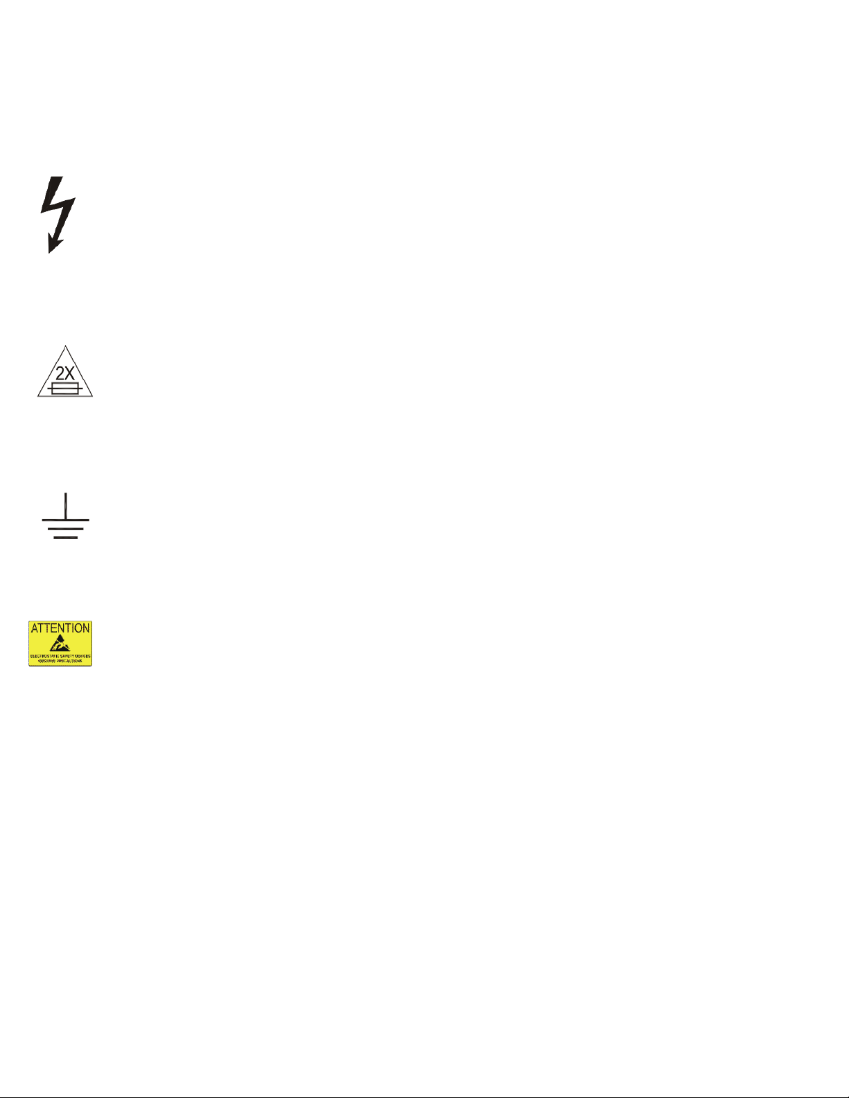
For continued protection against fire hazard, replace fuses with same type and rating only.
Connect the Precess MRI Patient Monitoring System to a three-wire, grounded, hospital-grade
receptacle only. The three-conductor plug must be inserted into a properly wired three-wire
receptacle.
Do not under any circumstances remove the grounding conductor from the power plug.
Avoid use of electrical power extension cords. Electrical power extension cords will create a
safety hazard by compromising the grounding integrity of the Precess MRI Patient Monitoring
System.
None of the interconnection ports on the rear of the DCU or WPU (e.g. Communication Ports,
Auxiliary Input/Output port [AUX I/O], USB port, Keyboard, Gating Connection or Video Input)
are intended for direct patient connection. An electric shock hazard can exist if the patient is
electrically connected to any of these connections.
The Precess MRI Patient Monitoring System and its listed accessories may be safely powered by
the voltages 100-240 VAC having a frequency of 50 or 60 Hz.
If the integrity of the earth ground conductor of the AC main power cable is in doubt, operate the
Precess MRI Patient Monitoring System on internal battery power until proper earth ground
connection is confirmed.
iv

PRECAUTIONS
Patient Safety
Whenever a patient is under anesthesia or connected to a ventilator constant attention by
qualified medical personnel is needed. Some equipment malfunctions may occur in spite of
equipment or monitoring alarms.
Always test the sampling line adapter for a tight connection and proper operation before attaching
to a patient.
As with all medical equipment, carefully route patient cabling to reduce the possibility of patient
entanglement or strangulation.
Occupational Safety
Connect the sample gas outlet on the monitor's rear panel to a scavenging system to prevent
pollution of room air.
Handle the Patient Sampling Line and its contents as you would any body fluid. Infectious hazard
may be present.
v

PRECAUTIONS
MRI Use Precautions
Certain components of the Precess MRI Patient Monitoring System will be affected by the
magnetic and radio frequency fields present in your MRI magnet room. Confer with your MRI
physicist and/or Radiology staff to identify the proper placement and use areas for the Precess
MRI Patient Monitoring System and its accessories, as defined on the system or accessory
labeling. Failure to properly place the Precess MRI Patient Monitoring System and its accessories
in the magnet room will result in system or accessory failure, and possible patient or user injury.
Possible damage to the NIBP or ETCO2 pump could occur. A dB/dT above 40T/second may
saturate the ECG amplifier of this device, leading to erratic readings. Always verify proper
communication of the Precess MRI Patient Monitoring System with the corresponding Remote
Monitor (Display Control Unit (DCU)) prior to patient use.
MRI Magnet Room Placement
The Precess MRI Patient Monitoring System is designed to be used in conjunction with a Remote
Monitor (Display Control Unit (DCU)).
The Precess MRI Patient Monitoring System is specially designed not to interfere with MRI
operations. IT MAY BE USED INSIDE THE MRI MAGNET ROOM IN A
LOCATION AT OR OUTSIDE THE 5,000 (5,000 OR LESS) GAUSS (0.5T)
FIELD LINE OF THE MRI SYSTEM, AS MEASURED FROM THE
CENTER LINE OF THE MRI BORE, BUT IN NO CASE CLOSER THAN
3 FEET (1 METER) FROM THE MRI SYSTEM. ALWAYS ENSURE THAT
THE WHEELS ARE IN THE LOCKED POSITION WHEN THE
MONITORING SYSTEM IS LEFT UNATTENDED.
Field strength variations in a particular MRI magnet room (which may be due to active shielding
technology, manufacturer variability, future enhancements, etc) can make distinguishing the 5,000
Gauss level difficult and therefore the Precess MRI Patient Monitoring System must never be
placed closer than 3 feet (1 meter) from the MRI System. This variation may require moving the
Precess MRI Patient Monitoring System away from the magnet if system abnormalities or
malfunctions are observed. Prior to clinical use, the operator must be aware of the minimum
distance from the MRI System for proper operation.
If brought closer than 3 feet (1 meter) and/or the 5,000 Gauss Field Line, system failure and/or
patient or user injury may result.
vi
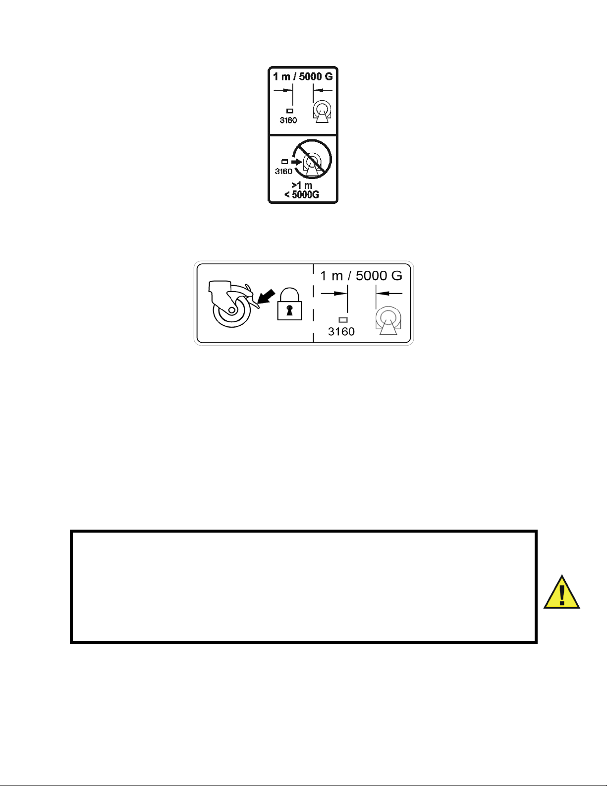
5,000 G/3 FT (1M), WHICHEVER IS FARTHER FROM THE MRI SYSTEM
ALWAYS ENSURE THAT THE WHEELS ARE IN THE LOCKED
POSITION WHEN THE MONITORING SYSTEM IS LEFT
UNATTENDED.
The Remote Monitor (Display Control Unit (DCU)) is also specifically designed not to interfere
with MRI operations. If the recorder option is present, it may be used in the magnet room at or
outside the 1,000 Gauss (0.1T) Field Line of the MRI System. Do not move the Remote Monitor
closer than the specified Gauss Field Line or damage (failure to operate) to the recorder may
result. If the recorder option is not present, the Remote Monitor may be used at or outside the
5,000 Gauss (0.5T) Field Line or no closer than 3 feet (1 meter) from the MRI System.
WARNING
If the Precess MRI Patient Monitoring System rolls to the face of the MRI
system due to magnetically induced pull force, DO NOT ATTEMPT TO
DISLODGE THE PRECESS MRI PATIENT MONITORING SYSTEM BY
PULLING FROM THE DOCKED REMOTE MONITOR OR GUIDE
HANDLE AT THE TOP OF THE PRECESS MRI PATIENT MONITORING
SYSTEM.
Dislodge the Precess MRI Patient Monitoring System by gently pulling from the base of the
system pole at its lowest point. This will prevent the base of the unit from experiencing higher
MRI pull forces in the vertical direction.
vii

PRECAUTIONS
Risk of RF current burn
Cables which become inadvertently looped during MRI act as conductive lines for RF induced
currents. When lead wires or other cables form a conductive loop in contact with the patient's
tissue, minor to severe burning can result.
Perform the following to minimize risk of RF current burn:
a. Place cables and lead wires neatly in straight alignment with no looping.
b. Use only the ECG Lead Wires designated for use with this product. See Accessory
List.
c. RF burn risk increases when multiple sensors/cables are in use. Such combinations
are not recommended.
d. The high radio frequency (RF) power used in MRI scanning poses an ever-present
risk of excessive heat at the monitoring sites and, therefore, the risk of RF current
burn. Power levels greater than S.A.R. of 4 w/kg increase the risk of patient
burns. As a result, monitoring of ECG at power levels of greater than 4 w/kg is not
recommended for the general patient population. Such monitoring must only be
attempted on conscious patients with good temperature reflex so they may warn
the operator of excessive heat at the monitoring sites.
e. High RF Power may cause patient heating or burns. Use caution for scan times
greater than 15 minutes. It is recommended that ECG electrode temperature be
checked during scans greater than 15 minutes.
MRI Compatibility
The Quadtrode MRI ECG Electrodes (Invivo Part Numbers 9303, 9371 and 9372), and ECG
Patient Lead Wires (Invivo Part Numbers 9224, 9223 and 9222), are compatible with Magnetic
Resonance Imaging (MRI) Systems within the following guidelines:
• MRI systems with static magnetic field strengths up to 3.0 Tesla.
• Usable within the MRI system bore with Specific Absorption Ratios (S.A.R.'s) up to
4.0 w/kg. Use with higher S.A.R.'s greatly increases the risk of patient burns. If scanned
directly across the plane of the ECG electrode element, a slight image distortion may be seen
at the skin surface where the electrode element is positioned.
viii

PRECAUTIONS
ECG
An inoperative ECG parameter or WECG module is indicated by absence of an ECG waveform
and a simultaneous Lead Fail alarm.
For best ECG, heart rate, and/or respiration monitoring, always select the optimal lead
configuration which has the least artifact and largest waveform(s) being detected for monitoring
use.
Failure to respond to a Lead Fail alarm will cause a lapse in your patient’s monitoring. Always
respond promptly to this and any other alarms.
Heart rate values may be adversely affected by cardiac arrhythmia, or by operation of electrical
stimulators.
NIBP
Always use recommended NIBP cuffs and hoses. Avoid compression or restriction of NIBP cuff
hose.
When using the NIBP portion of this instrument to measure blood pressure, remember that the
patient’s blood pressure readings are not continuous, but are updated each time a blood pressure
measurement is taken. Set a shorter interval for more frequent updating of the patient’s blood
pressure.
Do not attach the cuff to a limb being used for infusion. Cuff inflation can block infusion, possibly
causing harm to the patient.
Arrhythmias and/or erratic heart beats (or severe motion artifact, such as tremors or convulsions)
can result in inaccurate readings and/or prolonged measurements. If questionable readings are
obtained, re-check patient’s vital signs by alternate means before administering medication.
To ensure accurate and reliable measurements, use only recommended patient cuffs/hoses. Use
the appropriate cuff size for each patient as recommended by the current American Heart
Association (AHA) guidelines for blood pressure monitoring to ensure patient safety and
accuracy.
Routinely inspect the cuff and hose assemblies for proper attachment and orientation. Replace
cuff and/or hose assemblies with cracks, holes, tears, cuts, etc. that could cause leaks in the
system. If cuff and/or hose assemblies with damage which could result in leaks are used,
prolonged and/or inaccurate patient readings could result.
Use only cuffs designated by Invivo. See Accessory List on page xv.
This equipment complies in full to EN 1060-1:1996 + A1:2002, Specification for non-invasive
sphygmomanometers - Part 1: General requirements.
ix

PRECAUTIONS
SpO2
Avoid placement of the SpO2 sensor on the same limb with an inflated blood pressure cuff. Cuff
inflation could result in inaccurate readings and false alarm violations.
SpO2 monitoring requires the detection of valid pulses to correctly determine SpO2 and Heart
Rate values. During conditions of gross artifact, or in the absence of valid pulses, the SpO2/rate
values will not be correct.
The SpO2 patient monitoring portion of this system is intended to measure arterial hemoglobin
oxygen saturation of functional hemoglobin (saturation of hemoglobin functionally available for
transporting oxygen in the arteries). Significant levels of dysfunctional hemoglobins, such as
carboxyhemoglobin or methemoglobin, will affect the accuracy of the measurement. Also,
Cardiogreen and other intravascular dyes may, depending on their concentration, cause
inaccuracy of the SpO2 measurement.
Always shield the SpO2 sensor from extraneous incident light sources. Such extraneous light can
cause SpO2 reading or pulse detection errors.
Frequently inspect the SpO2 sensor site for possible pressure tissue necrosis during prolonged
monitoring. Reposition the sensor at least every four (4) hours. Special care must be exercised
when tape is used to secure the sensor, as the stretch memory properties of most tapes can easily
apply unintended pressure to the sensor site.
The numeric measurement values are updated every one (1) second on the system display.
A pulse oximeter should be considered an early warning device. As a trend towards patient
deoxygenation is indicated, blood samples must be analyzed by a laboratory co-oximeter to
completely understand the patient’s condition.
The pulse oximeter feature in this system is designed to display functional SpO2 values.
The pulse oximeter pulsatile waveform is not proportional to the pulse volume, but adjusts the
waveform amplitude as needed for proper viewing.
Arrhythmias and/or erratic heart beats (or severe motion artifact, such as tremors or convulsions)
can result in inaccurate readings and/or prolonged measurements. If questionable readings are
obtained, re-check patient’s vital signs by alternate means before administering medication.
Ambient light (including photodynamic therapy), physical movement (patient and imposed
motion), diagnostic testing, low perfusion, electromagnetic interference, electrosurgical units,
dysfunctional hemoglobin, presence of certain dyes and inappropriate positioning of the pulse
oximeter probe can all lead to inaccuracies of the pulse oximeter equipment.
x

PRECAUTIONS
Invasive Pressures
For best invasive pressure monitoring, always select the appropriate waveform scale for the
waveform being observed.
For invasive pressure monitoring, routinely inspect the catheter and/or pressure line for leaks after
zeroing. Always follow the pressure transducer/catheter manufacturer’s use recommendations.
Never place the pressure transducer(s) within the MRI bore. Transducer failure, inaccurate
readings or noisy MRI images can result.
Invasive blood pressure transducers are sensitive to vibrations that can occur during MRI
scanning, which can lead to pressure reading inaccuracies. Always mount the invasive blood
pressure transducer away from areas where vibration is likely to occur.
Non-physiological pulsatile invasive pressure waveforms (e.g., such as found during intra-aortic
balloon pump use) can lead to inaccurate blood pressure readings. If questionable values are
observed, re-check patient’s pressures by alternate means before administering medication or
therapy.
The fluid within the pressure transducer system is a conductive connection to the patient, and
must not contact other conductive parts, including earth ground.
Use only approved pressure transducers and cables, as listed in the Accessory Section.
Follow the safe use instructions that are supplied with the pressure transducer.
Respiration
When setting up respiration monitoring, always observe and adjust the respiration gain of the
system while watching the patient’s breathing efforts before completing selection of the gain
setting. Failure to do this can result in inaccurate readings, or false respiration detection.
xi

PRECAUTIONS
End-tidal CO2 (ETCO2)
Verify that the patient’s breathing efforts and timing coincide with the DCU waveform before
completion of the patient set-up.
The ETCO2/N2O measurement displays the sampled value within 1 second of when the gas was
sampled.
Frequently inspect the ETCO2 patient tubing. Avoid kinking of the ETCO2 patient tubing that can
result in leaking, reduction, or cut-off of the sample gas flow. Inaccurate gas measurements could
result.
ETCO2 patient tubing and its associated components are intended for single-patient use only.
Avoid cleaning or disinfecting these items for reuse. Inaccurate gas measurements could result.
To prevent inaccurate or missed readings, keep the ETCO2 patient tubing clear of any moving
mechanisms which may kink, cut or dislodge the patient tubing.
Do not allow tubing to become kinked so that the sample flow is reduced or cut off.
Do not overtighten the patient gas sample line to the water trap connector. Overtightening this
connector can cause failure of the water trap assembly and resultant inaccurate patient gas
measurements.
Leaks or internal venting of sampled gas will lead to inaccurate measurements.
CO2 and Anesthetic Agent calibration cylinders and test gas mixtures must be completely drained
of pressure before disposal.
Do not block the gas exhaust port on the rear of the Wireless Processing Unit (WPU).
Always inspect patient tubing after attachment to the system by following the patient tubing
manufacturer's recommendations.
Consult the instructions that come with the ETCO2 accessories, as they contain guidance
regarding the length of time that the components may be used.
An internal leak may result in condensation within the system. If this is suspected, please contact
Invivo.
The Precess contains an exhaust port at the rear of the WPU that may be connected to the facility's
anesthetic gas scavenging system, using the appropriate exhaust tube accessory. Follow the
facility's guidelines for connecting to the scavenging system, including proper disposal of
sampled gas.
Mainstream cyclical pressure of 10kPa can damage the equipment since this system uses
sidestream technology as the measurement technique.
Return of the sampled gas to the PCU will cause a positive pressure that can reduce flow which
can affect accuracy at higher breath rates. Accuracy is reduced because ETCO2 value will
decrease and inspired CO2 will, in turn, increase.
Temperature
Use only MRI-compatible fiber-optic temperature sensor accessories (see MRI Accessory List in
this section).
The fiber-optic temperature sensors are constructed of fiber-optic glass and must always be
handled with care to prevent damage. Improper handling can result in inaccurate readings and
shorten the temperature sensor's useful life.
xii

During longer term monitoring sessions (4 hours or more), frequent medical attention must be
given to the sensor site for possible pressure tissue necrosis , especially on tender skin of neonatal
patients.
Do not immerse complete sensor in any type of liquid.
xiii

PRECAUTIONS
Anesthetic Agents
Inadequate ventilation of the system will cause inaccurate readings or damage to electronic
components.
Do not block the gas exhaust port on the rear of the Wireless Processing Unit (WPU).
Ensure that the exhaust gas is not removed from the system under too strong a vacuum. To
prevent this condition, there must always be an opening to the room air. Too high a vacuum level
will change the operating pressure of the system and cause inaccurate readings or internal
damage.
Inspect gas exhaust/waste gas line for deterioration on a regular basis. Replace as needed.
Remove sampling line from patient airway whenever nebulized medications are being delivered.
Use only Invivo sampling lines and accessories; other sampling lines will cause inaccurate
readings and malfunctions.
Some Hydrocarbons (e.g. Acetone, Methane) will cause a mixed agent alarm to occur.
Replace the sampling line and inspect water trap between each patient use.
Do not overtighten the patient gas sample line to the water trap connector on the PCU.
Overtightening this connector can cause failure of the water trap assembly and result in inaccurate
patient gas measurements.
Routinely inspect the hose assemblies for proper attachment and orientation. Replace hose
assemblies with cracks, holes, tears, cuts, etc. that could cause leaks in the system. If hose
assemblies with damage that could result in leaks are used, prolonged and/or inaccurate patient
readings could result.
If questionable anesthetic agent gas measurements are observed, recheck patient connections,
anesthesia gas machine and/or vaporizer before re-adjusting anesthesia delivery.
With no gas reading (Agent Icon box with white X for agent identification and agent values of
“---”) when Agent Vaporizer is first turned on, it may take 30 seconds to 1.5 minutes for agent
identification and reading to be displayed. Once identification is established, changes in
concentration are virtually immediate. With a 200% change in concentration, an auto Zero will
occur, and full accuracy of the changed concentration will be accomplished within approximately
30 seconds.
Whenever the Precess MRI Patient Monitoring System Agent sensor changes from steady state
condition, the Precess MRI Patient Monitoring System will perform an auto zero to restabilize the
sensor readings. During this time, 15 seconds to 1.5 minutes, it is possible for a false
identification and concentration value to occur. Examples are as follows:
• No gas, during warm-up and when sample line is disconnected.
• Applying sample line for the first time.
• When switching from one Agent to another.
• Applying N2O in concentrations of 70% or more.
• Going from N2O of greater than 50% to 0%.
• When going from high Agent concentrations to low or off.
Leaks or internal venting of sampled gas will lead to inaccurate measurements.
CO2 and Anesthetic Agent calibration cylinders and test gas mixtures must be completely drained
of pressure before disposal.
xiv

PRECAUTIONS
Other
This product, or any of its parts, must not be repaired other than in accordance with written
instructions provided by Invivo, or altered without prior written approval of Invivo Corporation.
The user of this product shall have the sole responsibility for any malfunction which results from
improper use, faulty maintenance, improper repair, damage, or alteration by anyone other than
Invivo, or its authorized service personnel.
This patient monitoring system is equipped with a demonstration mode which displays simulated
electronic patient data for training or demonstration purposes. Do not attach a patient to the
system whenever this simulation is present on the DCU. (“SIMULATION” can also be seen in the
DCU. Failure to properly monitor the patient could result.
The patient connector inputs for all parameters are protected against the use of a defibrillator by
internal circuitry when the recommended patient cables or accessories are used. The use of this
circuitry and these recommended cables and accessories also protects against the hazards
resulting from use of high frequency surgical equipment.
Do not use two Precess MRI Patient Monitoring Systems in the same MRI room. This will lead
to communication errors.
A small but noticeable degradation for the ECG and SpO2 radio system will occur in the presence
of high powered radios.
There are no known electromagnetic interference or other hazardous interference between the
Precess MRI Patient Monitoring System and other devices. However, care must be taken to
avoid the use of cellular phones or other unintended radio-frequency transmitters in the proximity
of the monitoring system.
This system uses rechargeable batteries that contain hazardous material. These batteries must be
recycled, or disposed of properly. For proper disposal methods, contact Invivo representative or
distributor.
Avoid ammonia, phenol or acetone based cleaners for they will damage the system surfaces.
Dispose of the system and parts thereof according to local regulations.
The Precess MRI Patient Monitoring System has a defibrillation-proof type degree of
protection. When using a defibrillator, make sure to follow all precautions related to both the
system and the defibrillator equipment. During a defibrillation procedure, the ECG waveform will
saturate then recover in less than eight (8) seconds in accordance with AAMI/ANSI EC13.
When using a defibrillator, do not introduce discharges of 360 joules or more, repeated five (5)
times over five (5) minutes. Read safety instructions provided with the defibrillator. The Precess
is designed to withstand defibrillation and will recover within five (5) seconds (per IEC 60601-1).
xv

USER RESPONSIBILITY
This product will perform in conformity with the description contained in this operators manual
and accompanying labels and/or inserts, when assembled, operated, maintained and repaired in
accordance with the instructions provided. This product must be checked and calibrated
periodically. A malfunctioning product must not be used. Parts that are broken, missing, plainly
worn, distorted or contaminated must be replaced immediately. Should such repair or replacement
become necessary refer unit to qualified service personnel. This product or any of its parts must
not be repaired other than in accordance with written instructions provided by the manufacturer,
or altered without written approval of Invivo. The user of the product shall have the sole
responsibility for any malfunction which results from improper use, faulty maintenance, improper
repair, damage or alteration by anyone other than Invivo or Invivo authorized service personnel.
Using this Manual
Whenever the various options are discussed, “XXX” is used to indicate a variable setting. It is
required that every operator read this manual completely, including any patient information in
sections about monitoring features the operator’s system does not have, before attempting to
operate the Precess MRI Patient Monitoring System.
The figures contained in this manual show a fully equipped system. Therefore, figures within this
manual may depict monitoring features that your system may not contain. For information on
features and enhancements that are not contained in your system, contact Invivo at (407)
275-3220, or (US Toll-Free) 800-331-3220.
Precautions (listed earlier in this section) cover of wide ranges of information crucial to the safe
monitoring of patients. It is required that every operator read the PRECAUTIONS completely,
including the precautions associated with monitoring features that the operator’s system does not
have, before attempting to operate the Precess MRI Patient Monitoring System.
This device is covered under one or more of the following U.S. Patents: 5,482,036; 5,490,505;
5,632,272; 5,685,299; 5,758,644; 5,769,785; 6,002,952; 6,036,642; 6,067,462; 6,206,830;
6,157,850; 6,277,081 and international equivalents. U.S.A. and international patents pending.
Possession or purchase of this device does not convey any express or implied license to use the
device with replacement parts which would, alone, or in combination with this device, fall within
the scope of one or more of the patents relating to this device.
For further information or assistance with this product:
Invivo Corporation
407-275-3220, or
Toll-Free (US) 800-331-3220

Precess MRI Patient Monitoring Accessories
Item Description Part Number
General
Precess 14.8V Battery (each).....................................................................................................9093
Precess 14.4V Battery (each).....................................................................................................9064
Power Supply to Precess Cable, 5 Feet (1.6 M) ................................................................. AC517A
Power Supply to Precess Cable, 25 Feet (7.6 M) ............................................................... AC517B
Precess Power Adapter .......................................................................................................... AS201
Wireless Module Battery Charger
Precess Wireless Module Battery Charger.................................................................................9023
Power Cord 110V..................................................................................................................... AS18
Power Cord 10A 220-230V Europe.......................................................................................AS18G
Power Cord 220V Universal..................................................................................................AS18A
ECG
Quadtrode MRI ECG Electrode (box 10) ...............................................................................9303A
Quadtrode CV MRI ECG Electrode (box 10) ........................................................................9371A
Neonatal Quadtrode MRI ECG Electrode (box 10)................................................................9372A
Quadtrode MRI ECG Cable.......................................................................................................9224
Quadtrode CV MRI ECG Cable ................................................................................................9223
Neonatal Quadtrode MRI ECG Cable .......................................................................................9222
ECG Skin Prep Gel ....................................................................................................................9009
ECG Electrode Impedance Meter ..............................................................................................9392
Wireless ECG Module (Note: Wireless Network must be specified)........................................9312
Wireless Module Batteries.........................................................................................................9065
SpO2
Adult Grip Sensors (package of 3) ......................................................................................9399AA
Pediatric Grip Sensors (package of 3) ................................................................................. 9399AP
Infant Grip Sensors (package of 3) ....................................................................................... 9399AI
Neonatal Foot/Hand Grip Sensors (package of 3) ............................................................... 9399AN
SpO2 Grip Sensor ...................................................................................................................9399B
Wireless SpO2 Module (Note: Wireless Network must be specified).......................................9311
Wireless Module Batteries.........................................................................................................9065
SpO2 Clip Sensor................................................................................................................. 9399BC
NIBP
MRI Pediatric NIBP Cuff (9-25 cm) ......................................................................................9092B
MRI Adult Cuff (17-45 cm).................................................................................................... 9092C
MRI Large Adult NIBP Cuff (39-62 cm) ...............................................................................9092D
MRI Adult NIBP Hose ...........................................................................................................9092A
MRI Neonatal NIBP Hose ...................................................................................................... 9092E
Disposable Neonatal NIBP Cuff (6-11 cm) ............................................................................ 9092F
Disposable Neonatal NIBP Cuff (8-15 cm)............................................................................9092G
xvii

Precess MRI Patient Monitoring Accessories
Item Description Part Number
ETCO2
ETCO2 Sample Line Kit..........................................................................................................94021
ETCO2 Water Trap ..................................................................................................................94020
Adult Disposable Cannula .........................................................................................................9012
Pediatric Disposable Cannula ....................................................................................................9013
Infant Disposable Cannula.........................................................................................................9014
Small Infant Disposable Cannula ..............................................................................................9015
Adult Divided Cannula ..............................................................................................................9016
Pediatric Divided Cannula ...................................................................................................... 9016C
Infant Divided Cannula...........................................................................................................9016A
Small Infant Divided Cannula ................................................................................................9016B
Anesthetic Agents
Anesthetic Agents Sample Kit.................................................................................................94018
Anesthetic Agent Water Trap...................................................................................................94012
Disposable Oxygen (O2) Sensor................................................................................................9445
Anesthetic Agents Airway Adapter (package of 50) .................................................................9025
Temperature
Fiber-Optic Temperature Sensor ................................................................................................9320
Temperature Sensor Applicator .................................................................................................9321
Pneumatic Respiration
Chest Pneumograph Sensor .....................................................................................................94023
Invasive Pressures
Edwards Lifesciences TruWave Reusable Cable, Model PX1800.
Edwards Lifesciences Pressure Monitoring Kit with TruWave Disposable Pressure Transducer,
PX Series.
Gating
Philips Achieva Gating Interface Cable.....................................................................................9294
GE Excite Gating Interface Cable..............................................................................................9292
Siemens Avanto/Espree/Trio Gating Interface Cable ................................................................9291
Hitachi/Toshiba Gating Interface Cable.....................................................................................9293
xviii

SECTION 1
INTRODUCTION
1.0 INTRODUCTION.
This manual describes a fully configured Precess MRI Patient Monitoring System, and may
include features and/or options that are not included in your system. For additional information,
contact your local sales representative or Invivo Customer Service.
The Precess MRI Patient Monitoring System is intended for use by health care professionals. It is
intended to monitor vital signs for patients undergoing MRI procedures and to provide gating
signals for synchronization for the MRI scanner.
Specific training is required to operate this device. For available training options, please contact
Invivo Customer Service at 407-275-3220 or Toll-Free 1-888-221-1592.
Indications for Use
The Precess MRI Patient Monitoring System is intended to monitor vital signs for patients
undergoing MRI procedures and to provide signals for synchronization of the MRI scanner.
The Precess MRI Patient Monitoring System is intended for use by health care professionals.
1.1 Product Description. The Precess MRI Patient Monitoring System is designed to assist
clinicians in monitoring patient vital signs in the midst of the dynamic and evolving Magnetic
Resonance environment. The Precess combines the latest wireless communication, radio
frequency (RF) shielding, digital signal processing (DSP), and adaptable mounting technologies
to address the challenges associated with patient monitoring in the MRI area. Built on Invivo’s
strong heritage in MRI patient vital signs monitoring, the Precess provides accurate, continuous,
and reliable performance during MRI applications.
The standard Precess configuration consists of wireless interfaced electrocardiogram (ECG),
wireless interfaced pulse oximetry (SpO2), and non-invasive blood pressure (NIBP). Optional
parameters include end-tidal CO2 (ETCO2), anesthetic agents, invasive blood pressure (IBP) and
fiber-optic temperature.
The Precess system consists of the following components (See Figure 1-1):
a. Wireless Processing Unit. The Wireless Processing Unit (WPU) houses the
circuitry and hardware for support of the standard and optional patient monitoring
parameters. The transceivers and antennas that support wireless communication
with the ECG and SpO2 modules as well as the Display Controller Unit are also
part of the WPU. The unit is powered by an AC – DC power adapter or two
removable batteries that are recharged by the same power adapter. The batteries
provide approximately 8 hours of continuous operation when NIBP, ECG, and
SPO2 parameters are runing at 5-minute intervals. Refer to section 2.5 for more
information.
b. Patient Connection Unit. The Patient Connection Unit (PCU) contains the
connectors that support all the non-wireless parameters (i.e. NIBP, ETCO2, etc.).
c. Display Controller Unit. The WPU communicates to the Display Controller Unit
(DCU) via a bi-directional 2.4 GHz communication link. The large color LCD
display, keypad, and recorder of the DCU form an easy-to-use user interface for
display, control, and documentation of the system patient monitoring parameters.
1-1
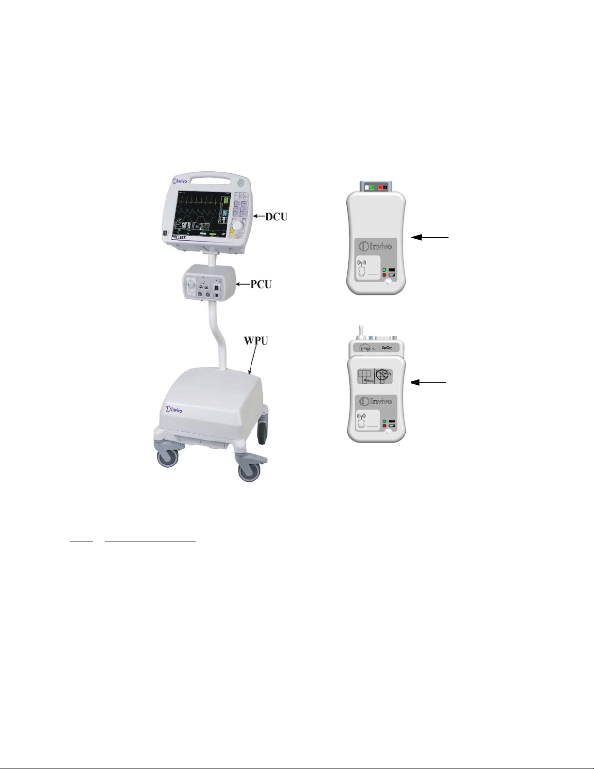
d. Wireless ECG Module. The Wireless ECG (WECG) module communicates two
leads of ECG simultaneously to the WPU. These two leads of ECG can be
displayed at the DCU and are output from the WPU unit for interface to the MRI
system cardiac gating input.
e. Wireless SpO2 Module. The Wireless SpO2 (WSpO2) communicates the SpO2
value and pulse waveform to the WPU. The information is available for display at
the DCU and is output from the WPU for interface to the MRI system pulse
peripheral gating input.
Wireless ECG
Module
Wireless SPO2
Module
Figure 1-1. Precess Components
1.1.1
simultaneous processing and display of up to eight (8) parameters, six (6) waveforms, and
associated numeric values from each different parameter. All of the patient information is clearly
displayed on a flat panel display screen.
The Precess MRI Patient Monitoring System includes the following vital sign parameters:
System Parameters. The Precess MRI Patient Monitoring System parameters allow
• Dual Lead ECG • Pulse Oximetry (SpO2) • NIBP
• ETCO2 • Pneumatic Respiration • Anesthetic Agents
• Temperature • Invasive Pressure (IBP)
1-2
1.1.2
learning time. On the Display Control Unit (DCU), there is a Rotary Knob (which detents from
selection to selection) that is used to access the parameter menus, access the various setup features
and finalize any changes to the setup of the system. Frequently used menus (such as Alarms,
Trends and Recorder) have a Control Key which, when pressed, will open the associated menu.
1.1.3 Versatility. With its diverse offering of vital sign parameters, the Precess MRI Patient
Monitoring System may be configured to meet the monitoring needs of a wide spectrum of
patients from Neonate to Adults. Every available parameter may be easily accessed and adjusted
to the unique needs, condition and situation of each patient.
1.2 Wireless Processor Unit (WPU). The WPU contains wireless transceivers, data
acquisition and processing circuitry that communicate with the wireless Display Control Unit
(DCU), ECG (WECG) module and SpO2 (WSpO2) module.
1.2.1 Operating Environment. The WPU is designed to operate at the 5,000 Gauss line in the
generated RF field of an MRI system measured from the center line of the bore.
1.2.2 Power Supply. The WPU Power Supply is designed to operate on the floor at least 10 feet
from a 3.0 Tesla unshielded MRI system (200 Gauss). When attached, the power supply charges
the WPU (and DCU) battery packs whether the WPU is operating or not.
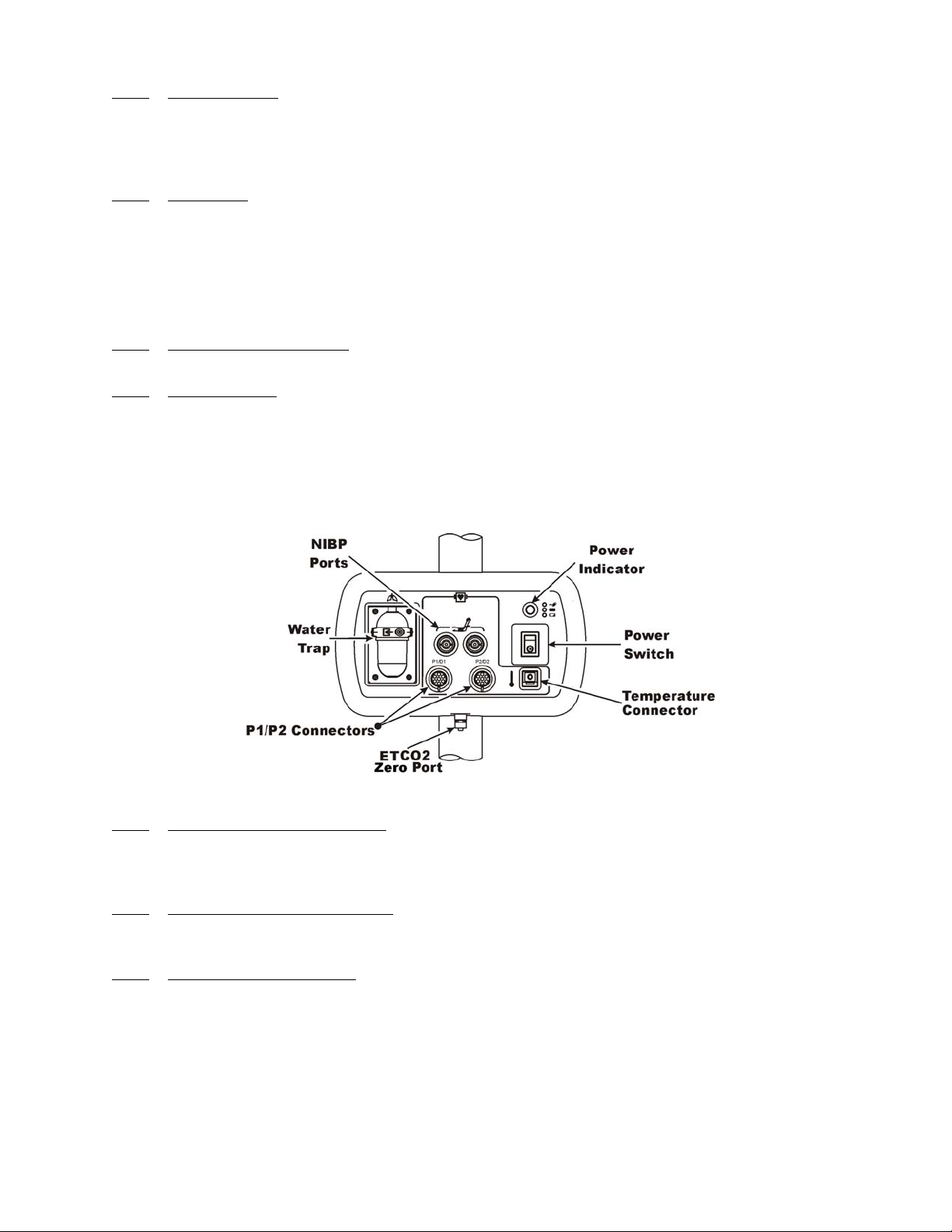
1.3 Patient Connections. The physical patient connections for NIBP, Invasive Pressure and
the Anesthetic Agents options are located on the Patient Connection Unit (PCU) (See Figure 1-2).
ECG, SpO2 and Pneumatic Respiration all use wireless technology to deliver their measurements
to the Wireless Processor Unit (WPU).
User Interface. A simple-to-use interface has been developed to minimize operator
Figure 1-2. Patient Connection Unit (PCU)
1.3.1
Invasive Blood Pressure (NIBP) and, when installed, the optional Anesthetic Agents parameters.
If Anesthetic Agents is installed, the PCU also contains a water trap to prevent moisture
contamination of the agent components.
1.3.2
invasive pressure channels, P1 and P2. Use the recommended Invasive Pressure Transducers that
are listed in the Accessories Section page xvii.
1.3.3 Temperature Monitoring. The PCU contains the physical connection for one temperature
channel. This Temperature Connector is for use with the fiber optic probe or sensor listed in the
Accessories Section on page xvii. Temperature values are displayed in °C or °F, as selected by the
operator.
1.4 ECG Monitoring. ECG is monitored using a Wireless ECG Module (WECG). The
WECG module converts the ECG signals into radio signals for transmission to the Wireless
Processor Unit (WPU). The module also receives information through the wireless link, converts
the information to electrical signals and performs the commanded task (i.e. lead configuration
change, scaling, etc.).
NIBP and Agent Monitoring. The PCU contains the physical connections for the Non-
Invasive Pressure Monitoring. The PCU contains the physical connections for two
1-3

• Compatibility. The WECG module supports the Quadtrode family of MRI
compatible ECG Electrodes.
• Visual Indicators. The WECG module contains one (1) bi-color LED that
indicates the status of the battery charge.
• Battery Life. The WECG module will operate at least eight (8) hours on a fully
charged battery.
1.5 SpO2 Monitoring. SpO2 is monitored using a Wireless SpO2 Module (WSpO2). The
Wireless SpO2 Module consists of a wireless transceiver to communicate with the Wireless
Processor Unit and convert the SpO2 pulse signal into radio signals for transmission to the
Wireless Processor Unit (WPU).
• Compatibility. The Wireless WSpO2 module utilizes a fiber optic SpO2 sensor.
• Visual Indicators. The WSpO2 module contains one (1) bi-color LED that
indicates the status of the battery charge.
• Battery Life. The WSpO2 module will operate at least eight (8) hours on a fully
charged battery.
1.6 Display Control Unit (DCU). The DCU provides control and display of the monitored
parameters.
1.6.1
for complete patient monitoring. Control is provided by the push button keys and Rotary Knob.
The Power Indicator is a three color LED that provides a visual indication of the DCU power
status with monitor power being turned off and on using the Power Switch. There is also a
Speaker to provide the sounds which the monitor produces and an Antenna for transmission/
reception of wireless signals. The following is a general description of the DCU.
DCU Controls. (See Figure 1-3) The DCU front panel contains all the controls and access
a. The Rotary Knob. The Rotary Knob is located to the right of the Display Screen.
The function of the Rotary Knob is menu specific. For this reason, its various
functions are described throughout this document where it is used; in general,
however, the Rotary Knob operates as described below:
(1) As the Rotary Knob is rotated, either clockwise or counterclockwise, the
DCU display “scrolls” through the various screen items (screen icons,
menu options and patient parameters) which are available for selection.
When the appropriate item is “highlighted,” it may be selected by pressing
and releasing the Rotary Knob. All menus have a RETURN option which
will return the display to the previous menu selection.
1-4
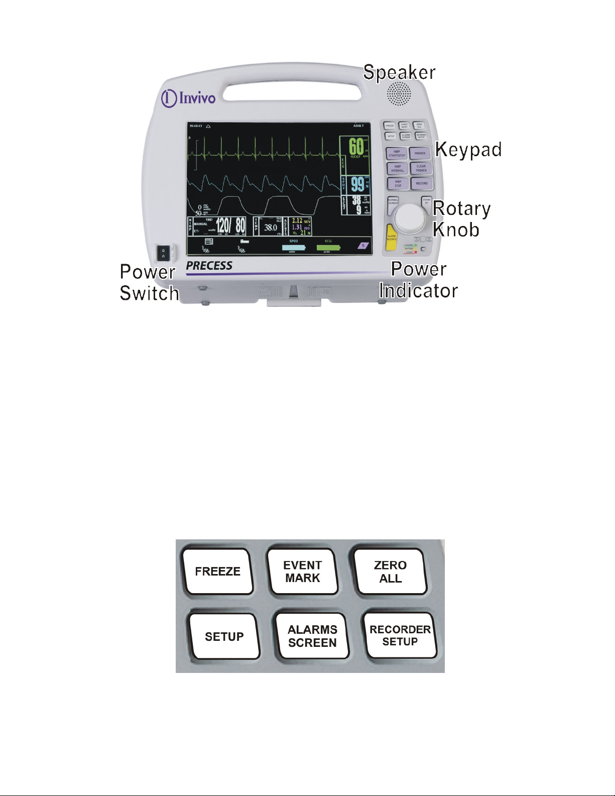
Figure 1-3. The DCU Front Panel
(2) During normal operation each active parameter has a Menu-Select icon on
the DCU display. When the Rotary Knob is rotated, the Menu-Select icon
which is being pointed at becomes “highlighted.” Rotating the Rotary
Knob will cause the display to “scroll through” the available menu
selections. Once the appropriate Menu-Select icon is highlighted, pressing
the Rotary Knob completes the selection and brings up the required menu.
Once the menu is selected, the Rotary Knob is used to scroll through the
available menu choices and make adjustments to the selected parameter.
The following Menu-Select Icons may be available on the Normal Screen
(depending on which parameters are available, enabled and turned on):
ECG, NIBP, SpO2, ETCO2, Agents, Invasive Pressures, and Temperature.
b. The Top Keypad Set. (See Figure 1-4) There are six push keys in the top keypad
set. The top three (FREEZE, EVENT MARK and ZERO ALL) provide direct
control of a system feature while the bottom three (SETUP, ALARMS SCREEN
and RECORDER SETUP) provide access to operational menus. The six push keys
are described below.
Figure 1-4. The DCU Top Keypad Set
1-5

:
(1) FREEZE. The Precess MRI Patient Monitoring System freezes the ECG
waveform from Trace A for closer examination upon user demand. When
the ECG trace is active, pressing the FREEZE key will freeze it into the
Trace B location while Trace A remains active. When the trace is frozen,
pressing the FREEZE key will release it. A “Blue Box” appears around the
frozen waveform as a visual indication that the waveform is not active.
While the Freeze feature is active, the monitor will not allow any changes
to the Parameter Setups or Display; if the operator attempts to access the
Parameter Selection Menu, a WARNING Box alerts the operator that entry
to the selected menu is not allowed while FREEZE is Enabled.
(2) EVENT MARK. The EVENT MARK key prints a marker on the ECG
Recorder Strip when the printer is running. If the printer is not running,
pressing this key has no effect.
(3) ZERO ALL. The ZERO ALL key initiates a zero of the pressure
transducer of all available invasive pressure channels.
(4) SETUP. The SETUP key allows the operator to access the various
available setup options.
(5) ALARMS SCREEN. The ALARMS SCREEN key is a dual function key
that allows the operator to setup the Alarms monitoring feature. When the
monitor display is in the Normal Screen and the ALARMS SCREEN key
is pressed, the Main Alarm Setup Screen will appear. When the monitor
display has any icon highlighted and the ALARMS SCREEN key is
pressed, an Alarm Setup Screen for the highlighted parameter appears.
(6) RECORDER SETUP. The RECORDER SETUP key allows the operator
to setup the Recorder option.
c. The Middle Keypad Set. (See Figure 1-5) The middle keypad set contains six
push keys. The three on the left provide control of the NIBP monitoring feature
with two of the keys (NIBP START/STOP and NIBP STAT) providing direct
control of NIBP measurements and the third (NIBP INTERVAL) bringing up a
menu that allows adjustment of the NIBP Auto Mode Interval feature. On the right
side of this set are two keys which control the Trending feature of the monitor
(TRENDS and CLEAR TRENDS) while a third (RECORD) provides a hardcopy
printout of selected parameters as specified by operator adjustments in the
Recorder Menu. The six push keys are described below.
1-6
 Loading...