


To navigate within this document:
1.Click the "Table of Contents" Bookmark on the left.
2.Click on the blue hyperlinked text to view the desired information.
Invivo Research, Incorporated
Millennia® 3155MVS/3155A Monitors
Service Manual
INVIVO
RESEARCH
INCORPORATED
12601 Research Parkway Orlando, FL 32826 1-800-331-3220 1-407-275-3220 www.invivoresearch.com


TABLE OF CONTENTS
Paragraph Number |
Page Number |
List of Figures . . . . . . . . . . . . . . . . . . . . . . . . . . . . . . . . . . . . . . . . . . . . . . . . . . . . . . . . . . . . . . . iii General Service Precautions . . . . . . . . . . . . . . . . . . . . . . . . . . . . . . . . . . . . . . . . . . . . . . . . . . . iv MRI Service Precautions . . . . . . . . . . . . . . . . . . . . . . . . . . . . . . . . . . . . . . . . . . . . . . . . . . . . . . . v User Responsibility . . . . . . . . . . . . . . . . . . . . . . . . . . . . . . . . . . . . . . . . . . . . . . . . . . . . . . . . . vii
1.0 THEORY OF OPERATION . . . . . . . . . . . . . . . . . . . . . . . . . . . . . . . . . . . . . . . . . . . . 1-1 1.1 General Description . . . . . . . . . . . . . . . . . . . . . . . . . . . . . . . . . . . . . . . . . . . . . . . . . . . . 1-1 1.1.1 System Parameters . . . . . . . . . . . . . . . . . . . . . . . . . . . . . . . . . . . . . . . . . . . . . . . 1-2 1.1.2 User Interface . . . . . . . . . . . . . . . . . . . . . . . . . . . . . . . . . . . . . . . . . . . . . . . . . . . 1-2 1.1.3 Versatility . . . . . . . . . . . . . . . . . . . . . . . . . . . . . . . . . . . . . . . . . . . . . . . . . . . . . . 1-2
1.2 Power Supply . . . . . . . . . . . . . . . . . . . . . . . . . . . . . . . . . . . . . . . . . . . . . . . . . . . . . . . . . 1-3 1.2.1 AB69 and AB69A Location . . . . . . . . . . . . . . . . . . . . . . . . . . . . . . . . . . . . . . . . 1-3 1.2.2 Charger Circuit . . . . . . . . . . . . . . . . . . . . . . . . . . . . . . . . . . . . . . . . . . . . . . . . . . 1-3 1.2.3 Power On/Off System . . . . . . . . . . . . . . . . . . . . . . . . . . . . . . . . . . . . . . . . . . . . 1-4 1.2.4 +5 and +3.3 Vdc Power Supplies . . . . . . . . . . . . . . . . . . . . . . . . . . . . . . . . . . . . 1-5 1.2.5 +12 and -12 Vdc Supplies . . . . . . . . . . . . . . . . . . . . . . . . . . . . . . . . . . . . . . . . . 1-6 1.2.6 Clock Generator . . . . . . . . . . . . . . . . . . . . . . . . . . . . . . . . . . . . . . . . . . . . . . . . . 1-7 1.2.7 Audio . . . . . . . . . . . . . . . . . . . . . . . . . . . . . . . . . . . . . . . . . . . . . . . . . . . . . . . . . 1-7 1.2.8 Power Sense for POWER GOOD . . . . . . . . . . . . . . . . . . . . . . . . . . . . . . . . . . . 1-7 1.2.9 Battery/AC Power Sense . . . . . . . . . . . . . . . . . . . . . . . . . . . . . . . . . . . . . . . . . . 1-7 1.2.10 Recorder Power . . . . . . . . . . . . . . . . . . . . . . . . . . . . . . . . . . . . . . . . . . . . . . . . . 1-8
2.0 CALIBRATION AND VERIFICATION . . . . . . . . . . . . . . . . . . . . . . . . . . . . . . . . . . |
2-1 |
2.0.1Required Test Equipment. . . . . . . . . . . . . . . . . . . . . . . . . . . . . . . . . . . . . . . . . . 2-1
2.0.2 Agents Test Equipment. . . . . . . . . . . . . . . . . . . . . . . . . . . . . . . . . . . . . . . . . . . . 2-1 2.1 Turning the Monitor On . . . . . . . . . . . . . . . . . . . . . . . . . . . . . . . . . . . . . . . . . . . . . . . . . 2-1 2.2 Front Panel Control Verification . . . . . . . . . . . . . . . . . . . . . . . . . . . . . . . . . . . . . . . . . . 2-2 2.2.1 Rotary Knob Verification . . . . . . . . . . . . . . . . . . . . . . . . . . . . . . . . . . . . . . . . . . 2-2 2.2.2 Control Key Verification . . . . . . . . . . . . . . . . . . . . . . . . . . . . . . . . . . . . . . . . . . 2-3
2.3 System Cold Start Procedure . . . . . . . . . . . . . . . . . . . . . . . . . . . . . . . . . . . . . . . . . . . . . 2-5 2.4 Sound System Verification and Adjustment . . . . . . . . . . . . . . . . . . . . . . . . . . . . . . . . . 2-5 2.5 Time Set Verification . . . . . . . . . . . . . . . . . . . . . . . . . . . . . . . . . . . . . . . . . . . . . . . . . . . 2-6 2.6 Store and Recall Setups . . . . . . . . . . . . . . . . . . . . . . . . . . . . . . . . . . . . . . . . . . . . . . . . . 2-7 2.6.1 Cold Start Verification . . . . . . . . . . . . . . . . . . . . . . . . . . . . . . . . . . . . . . . . . . . . 2-8 2.7 Remote Communication System Verification . . . . . . . . . . . . . . . . . . . . . . . . . . . . . . . . 2-8 2.7.1 Remote Parameter Verification . . . . . . . . . . . . . . . . . . . . . . . . . . . . . . . . . . . . . 2-9
2.8 Recorder Verification . . . . . . . . . . . . . . . . . . . . . . . . . . . . . . . . . . . . . . . . . . . . . . . . . . . 2-9 2.9 Agents Verification (Millennia® 3155A Only) . . . . . . . . . . . . . . . . . . . . . . . . . . . . . . . 2-10
3.0 ASSEMBLY/DISASSEMBLY PROCEDURES . . . . . . . . . . . . . . . . . . . . . . . . . . . . 3-1
3.0.1Required Tools. . . . . . . . . . . . . . . . . . . . . . . . . . . . . . . . . . . . . . . . . . . . . . . . . . 3-1
3.1 Monitor Disassembly/Reassembly . . . . . . . . . . . . . . . . . . . . . . . . . . . . . . . . . . . . . . . . . 3-1 3.2 AB69 and AB69A Removal/Replacement . . . . . . . . . . . . . . . . . . . . . . . . . . . . . . . . . . 3-1 3.3 EMI Gasket Removal/Replacement . . . . . . . . . . . . . . . . . . . . . . . . . . . . . . . . . . . . . . . . 3-2 3.4 Battery Removal/Replacement . . . . . . . . . . . . . . . . . . . . . . . . . . . . . . . . . . . . . . . . . . . . 3-2 3.5 DC Fuse Removal/Replacement . . . . . . . . . . . . . . . . . . . . . . . . . . . . . . . . . . . . . . . . . . 3-3 3.6 AS153/AS153J Removal/Replacement . . . . . . . . . . . . . . . . . . . . . . . . . . . . . . . . . . . . . 3-3
3.6.1 AC Fuse Removal/Replacement . . . . . . . . . . . . . . . . . . . . . . . . . . . . . . . . . . . . 3-3 3.7 Anesthetic Oxygen Sensor Removal/Replacement (Millennia® 3155A Only) . . . . . . . 3-3 3.8 HE61 Radio Antenna Removal/Replacement . . . . . . . . . . . . . . . . . . . . . . . . . . . . . . . . 3-4
i

TABLE OF CONTENTS
Paragraph Number |
Page Number |
4.0 ADJUSTMENT PROCEDURES . . . . . . . . . . . . . . . . . . . . . . . . . . . . . . . . . . . . . . . . 4-1 4.1 Introduction. . . . . . . . . . . . . . . . . . . . . . . . . . . . . . . . . . . . . . . . . . . . . . . . . . . . . . . . . . . 4-1 4.2 Setup . . . . . . . . . . . . . . . . . . . . . . . . . . . . . . . . . . . . . . . . . . . . . . . . . . . . . . . . . . . . . . . 4-1 4.3 Power Supply Calibration . . . . . . . . . . . . . . . . . . . . . . . . . . . . . . . . . . . . . . . . . . . . . . . 4-2 4.4 Agents Adjustment Procedure (Millennia® 3155A Only). . . . . . . . . . . . . . . . . . . . . . . . 4-4
4.5Clock Adjustment Procedure. . . . . . . . . . . . . . . . . . . . . . . . . . . . . . . . . . . . . . . . . . . . . 4-6
5.0 PROGRAMMING INSTRUCTIONS . . . . . . . . . . . . . . . . . . . . . . . . . . . . . . . . . . . . 5-1 5.1 Introduction . . . . . . . . . . . . . . . . . . . . . . . . . . . . . . . . . . . . . . . . . . . . . . . . . . . . . . . . . . 5-1 5.2 Required Test Equipment . . . . . . . . . . . . . . . . . . . . . . . . . . . . . . . . . . . . . . . . . . . . . . . . 5-1 5.3 Com24 Setup . . . . . . . . . . . . . . . . . . . . . . . . . . . . . . . . . . . . . . . . . . . . . . . . . . . . . . . . . 5-1 5.4 Monitor Setup . . . . . . . . . . . . . . . . . . . . . . . . . . . . . . . . . . . . . . . . . . . . . . . . . . . . . . . . 5-2 5.5 HE60 Programming for Single 3155 Communications . . . . . . . . . . . . . . . . . . . . . . . . . 5-3 5.6 HE60 Programming for 3150/AS163 Communications . . . . . . . . . . . . . . . . . . . . . . . . 5-5 5.7 AB182B Programming for Dual 3155 Communications . . . . . . . . . . . . . . . . . . . . . . . . 5-7
6.0 TROUBLESHOOTING FLOW CHARTS . . . . . . . . . . . . . . . . . . . . . . . . . . . . . . . . 6-1
Appendix A: List of Symbols . . . . . . . . . . . . . . . . . . . . . . . . . . . . . . . . . . . . . . . . . . . . . . . . A-1
Appendix B: Repair . . . . . . . . . . . . . . . . . . . . . . . . . . . . . . . . . . . . . . . . . . . . . . . . . . . . . . . . . B-1
Appendix C: Warranty . . . . . . . . . . . . . . . . . . . . . . . . . . . . . . . . . . . . . . . . . . . . . . . . . . . . . . C-1
Appendix D: Electromechanical Specifications . . . . . . . . . . . . . . . . . . . . . . . . . . . . . . . . . D-1
ii

LIST OF FIGURES
Figure Number |
Page Number |
1-1. Sample 3155A Telecommunications Link Label . . . . . . . . . . . . . . . . . . . . . . . . . . . . . . 1-2 2-1. The Millennia® 3155MVS/3155A Monitor Front Panel . . . . . . . . . . . . . . . . . . . . . . . . 2-3 4-1. Power Supply Test Setup . . . . . . . . . . . . . . . . . . . . . . . . . . . . . . . . . . . . . . . . . . . . . . . . 4-2 4-2. TF0088 Assembly Instructions . . . . . . . . . . . . . . . . . . . . . . . . . . . . . . . . . . . . . . . . . . . 4-4 B-1. Sample Monitor ID Label . . . . . . . . . . . . . . . . . . . . . . . . . . . . . . . . . . . . . . . . . . . . . . . B-1 B-2. Sample Assembly/Subassembly Label . . . . . . . . . . . . . . . . . . . . . . . . . . . . . . . . . . . . . . B-2
iii
GENERAL SERVICE PRECAUTIONS
Obtain a thorough understanding of each of the following precautions before attempting to perform any disassembly or service procedure. Damage to the instrument or injury to yourself may result if these precautions, as well as common sense, are not used.
Service to this product should be performed at the recommended intervals only by trained, qualified service personnel familiar with the operation and service documentation for this monitor.
Shock Hazard exists when this monitor is operated without the chassis cover. Use caution when working on units with power applied.
Always disconnect monitor from AC Main Power before performing service on internal assemblies.
Due to the monitor's internal battery, power may be present even when disconnected from the AC Main Power. When necessary, disconnect the internal battery prior to performing service.
For continued protection against fire hazard, replace fuses with same type and rating only.
Always follow proper electrostatic discharge (ESD) procedures during component and assembly handling to prevent static discharge damage to sensitive parts.
Use only replacement parts specified in this manual; ensure that defective or worn parts are properly disposed of in accordance with local regulations.
When cleaning the unit, do not permit liquid to enter the case. When cleaning, use proper materials and ensure total dryness before powering the monitor. Use care that cleaning fluids do not attack plastic or painted surfaces (e.g., avoid ammonia, phenol or acetone based cleaners that may damage the monitor surface). Use care that wiping rags do not abrade the surfaces.
Assembly hardware has been secured with a thread disassembly cycles new locking agent will be required. near PVC or acrylic plastics.)
locking agent. After several assembly/ (Use Loctite 42540 or similar type for use
In general, handle all Printed Circuit Boards by their edges. Oils, sweat, dirt, etc. can induce leakage paths in high impedance circuits which impede their operation. Such contamination will also promote corrosion of circuits yielding a long term reliability problem.
Avoid rough handling of all exposed chassis parts and front panel overlay. These parts can be scratched causing obtrusive cosmetic defects.
iv

MRI SERVICE PRECAUTIONS
NOTE
In addition to these precautions, cautions and warnings are located in paragraphs 3.1 (Page 3-1), 4.0 (Page 4-1), Section 6 (Pages 6-1 through 6-10) and Appendix B (Page B-2).
CAUTION
Federal law in the USA and Canada restricts this device to sale by, or on the order of, a licensed medical practitioner.
This monitor is not intended for use in the presence of FLAMMABLE ANESTHETICS. An explosion hazard exists.
Never immerse the monitor in any fluid or attempt to clean it with liquid cleaning agents. An electrical hazard exists.
Do not remove the monitor's cover. A shock hazard exists. Refer servicing to qualified personnel only. No repair should be undertaken or attempted by anyone not having a thorough understanding of the repair and safety assurance of patient monitors.
Risk of RF current burn. Cables which become inadvertently looped during MRI act as conductive lines for RF induced currents. When lead wires or other cables form conductive loop in contact with the patient's tissue, minor to severe burning can result.
Perform the following to minimize risk of RF current burn:
1.Place cables and lead wires neatly in straight alignment with no looping.
2.Keep the length of lead wires and patient cable within the bore to a minimum.
3.RF burn risk increases when multiple sensors/cables are in use. Such combinations are not recommended.
4.The high radio frequency (RF) power used in MR scanning poses an ever-present risk of excessive heat at the monitoring sites and, therefore, the risk of RF current burn.
Should power levels greater than S.A.R. of 4 w/kg peak (0.4 w/kg average) be used, the risk of patient burn greatly increases. As a result, monitoring of ECG or Respiration (derived from ECG leads) at power levels of greater than 4 w/kg peak (0.4 w/kg average) is not recommended for the general patient population. Such monitoring should only be attempted on conscious patients with good temperature reflex so they may warn the operator of excessive heat at the monitoring sites.
5.High RF Power may cause patient heating or burns. For scans with average S.A.R. > 1 w/kg, limit scan time to 5 minutes and pause at least 3 minutes between scans to allow ECG Cable to cool.
NOTE
Use only Invivo Research Fiber Optic Sensors with this monitor.
v

MRI Compatibility
The QuadtrodeTM MRI ECG Electrode Pad, and ECG Patient Lead Wires and Cable, are compatible with Magnetic Resonance Imaging (MRI) Systems within the following guidelines:
!MRI Systems with static magnetic field strengths up to 1.5 Tesla.
!Usable within the MRI system bore with Specific Absorption Ratios (S.A.R.'s) up to 4.0 w/kg (peak). Use with higher S.A.R.'s greatly increases the risk of patient burns.
!Non-magnetic materials are used in the construction of these assemblies.
!If scanned directly across the plane of the ECG electrode element, a slight image distortion may be seen at the skin surface where the electrode element is positioned.
vi
USER RESPONSIBILITY
This product will perform in conformity with the description contained in the Operations Manual for the Millennia® 3155A/3155MVS Monitors (IRI Part Number 9545) and accompanying labels and/or inserts, when assembled, operated, maintained, and repaired in accordance with the instructions provided. This product must be checked and calibrated periodically. Recommended calibrations should be performed every six months. Operational checks should be done with each use.
A defective product should not be used. Parts that are broken, missing, plainly worn, distorted, or contaminated should be replaced immediately. Should such repair or replacement become necessary, Invivo Research, Incorporated (IRI) recommends that a telephone call or written request for service be made to the nearest factory service center. This product or any of its parts should not be repaired other than in accordance with written instructions provided by IRI or altered without the prior written approval of IRI. The user of the product shall have the sole responsibility for any malfunction which results from improper use, faulty maintenance, improper repair, damage, or alteration by anyone other than IRI authorized service personnel.
There are no user maintenance requirements. All maintenance requirements are to be done by qualified Service Personnel only.
vii
[THIS PAGE INTENTIONALLY LEFT BLANK.]
viii
SECTION 1
THEORY OF OPERATION
1.0THEORY OF OPERATION
NOTE
This manual describes a fully configured monitor, and may include features and/or options that are not included in your monitor. For additional information, contact your local sales representative, or Invivo Research, Inc. Customer Service.
NOTE
The drawings referenced in this section are located in Volume II of the Service Manual.
NOTE
Refer to the Millennia® 3155A/3155MVS Monitor Operations Manual
(IRI Part Number 9545) for the installation instructions and operating procedures pertaining to this unit.
1.1 General Description. The Millennia® 3155MVS/3155A Monitor is the Remote Control Unit in the Invivo Research, Incorporated 3150 Series MRI Monitoring System. This monitor provides Remote Control (through a cable or RF Radio Link) to a Omni-TrakTM 3150/MagnitudeTM 3150M MRI Patient Monitor (located in the MRI Magnet Room). Used with the Omni-TrakTM
3150 MRI Patient Monitor, the Millennia® 3155MVS/3155A Monitor provides four waveform traces compiling, processing, analyzing and displaying patient data from up to seven different patient parameters. The information that this Monitoring System is capable of supplying to the physician may be used as an aid in the determination of a diagnosis concerning the condition of a patient. There is no direct patient connection to the Millennia® 3155MVS/3155A Monitor (patient connection is performed in the Magnet Room with the Omni-TrakTM 3150/MagnitudeTM 3150M MRI Patient Monitor) except in the case of Agent monitoring when the Millennia® 3155A is used with the patient sample line connected directly into the front of the monitor. The Millennia® 3155MVS/3155A Monitor is compact, comes equipped with up to three batteries to supply emergency and/or transport power plus may "float" between the Magnet Room and Control Room (as determined by the needs of each unique monitoring situation). It also contains (as a optional feature) a recorder designed to provide printouts of the concise charts and trends required by today's specialists for analysis and documentation. The Millennia® 3155MVS/3155A can be used inside the MRI Magnet Room when positioned at or outside the 1000 Gauss (0.1T) Field Line. For the purposes of this manual, the Omni-TrakTM 3150 and MagnitudeTM 3150M MRI Patient Monitors will be referred to as the 3150/3150M and the Millennia® 3155A and 3155MVS Monitors will be referred to as the 3155MVS/3155A.
During MRI procedures that require anesthetic agents monitoring, where the 3155A is used in the MRI exam room, the dual monitor system (software MDC01 and higher) allows the operator to add a 3155MVS to the MRI monitoring system. The 3155MVS and 3155A interact through the 3150/3150M to allow monitoring at a remote site (such as the MRI control room).
1-1
NOTE
The 3150/3150M ETCO2 is turned Off when the Agent/ETCO2 is turned On at the Millennia® 3155A.
When the Millennia® 3155A is used to monitor Agent/ETCO2, it must be located in the Magnet Room with the gas sample line connected directly to the front of the 3155A.
If operating a dual monitor system, the 3155MVS and 3155A patient monitors are interactive with one another through the 3150/3150M. As the “communication unit” the 3150/3150M acts to keep the commands that control patient parameter function synchronized throughout the MRI monitoring system. Should the 3150/3150M be turned off, it is possible to have patient parameters on the 3155A set to a particular configuration with the 3155MVS set to a different configuration; when the 3150/3150M is turned on the system will synchronize and all patient configurations will reflect the 3155A configuration.
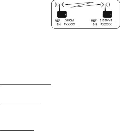
In a dual monitor system, a Telecommunications Link Label (See Figure 1-1) is affixed to each monitor. On the 3150 monitor, the label is located on the base assembly next to the “CE” compliance label. This label is located below the Monitor ID Label (See Figure B-1) on the rear panels of the 3155MVS and 3155A monitors. Each label identifies the Model and Serial Number of the remaining two units that make up the dual monitor system. The AB182B transceivers located in the three units are specifically preprogrammed at the factory for wireless radio telemetry intercommunication.
Figure 1-1. Sample 3155A
Telecommunications Link Label
The 3155MVS/3155A Monitor provides control and display of the following Vital Sign Parameters:
! ECG |
! |
NIBP |
! Two Invasive Blood Pressures |
! Pulse Oximetry |
! |
ETCO2 |
! Respiration |
! N2O |
! |
O2 |
! Identifies and measures Five (5) Major |
|
|
|
Anesthetic Agents |
1.1.1System Parameters. The 3155MVS/3155A System Parameters allow simultaneous processing and display of up to four parameter waveforms and associated numeric values from each different parameter. All the Patient Information is clearly displayed on a Flat Panel Display Screen.
1.1.2User Interface. A simple to use interface has been developed to minimize operator learning time. A Rotary Knob, which detents from selection to selection, is used to access the parameter menu's, access the various setup features and finalize any changes to the setup of the monitor. Frequently used menus (e.g., Alarms, Trends and Recorder) have a Control Key which, when pressed, will open the associated menu.
1.1.3Versatility. With its complete offering of vital sign parameters, the 3155MVS/3155A Monitor may be configured to meet the monitoring needs of a wide spectrum of patients from
1-2

Neonate to Adults. Every available parameter may be easily accessed and adjusted to the unique needs, condition and situation of each patient.
1.2 Power Supply. Power is supplied to this monitors operational circuits by the AB69 and AB69A Power Supply Boards. AB69 and AB69A supply +12 Vdc, -12 Vdc, +5 Vdc, -5 Vdc and +3 Vdc to the different operational areas of the Millennia® 3155 MVS/3155A Monitor. This power is used to run the recorder, provide alarm audio drive to the speaker and to provide front-panel LED illumination as an indication of the state of the input power and the condition of the batteries. In terms of the battery system: the AB69 and AB69A boards charge and monitor the charge-state of the batteries, provide operation from the batteries in the event of power failure or AC Line Power adapter disconnection, issues an early warning when the batteries are low and provides for controlled shut down of the monitor when the batteries are discharged.
1.2.1AB69 and AB69A Location. The AB69 and AB69A Power Supply Boards are stacked with the AB69A on top. They are located immediately in front of the Processor Motherboard in the center of the case.
1.2.2Charger Circuit. The charger circuit is located on the AB69A board (upper board, on the left half of the board. Please refer to the left half of drawing 185C197. The circuit is a buck-type switching regulator with current limiting and a charge-cutoff circuit.
Consider the charger switcher first: Q1, the current switch transistor, is driven by transistor Q4. A typical cycle of switching proceeds as follows: transistor Q1 turns on and applies the supply voltage (typically 18 to 14 volts) to inductor L1. The current through inductor L1 ramps up until the voltage across resistor R17, and the voltage between the emitter and the base of transistor Q3 rises enough to turn on transistor Q3. When transistor Q3 turns on, it shorts out the base-emitter drive into transistor Q2, and Q2 turns off. Transistor Q4 shuts off as there is now no current through resistor R14, and thus no voltage drop. When transistor Q4 turns off, transistor Q1 has no drive, and its output voltage falls to zero. The current through inductor L1 decays according to its time-constant, with diode D8 supplying the decaying current. Capacitor C4 smooths the output voltage from inductor L1. The overall action produces a set of rising and falling current-ramp waveforms that average out to a controlled charging current into the battery.
When the battery has charged sufficiently, the voltage on op amp U1 pin 2 now rises above the voltage on pin 3, and pin 1's voltage falls to ground. This forward-biases diode D3 with current being drawn through resistors R9 and R11. The voltage across resistor R11 is now enough to turn on transistor Q5. When transistor Q5 turns on, the base-emitter voltage across transistor Q2 becomes zero, and transistor Q2 turns off. This action will override the switching action just described and turn the charger off. The charger stays off until the battery voltage drops enough to initiate charging.
When the voltage on U1 pin 2 falls below that of pin 3, then pin 1 of U1 rises, turning off diode D3, and allowing the transistor Q2 to again have bias. The charger restarts. The circuit of resistor R8 and the diode D4 apply hysterises to avoid rapid charger cycling. Typically, the charger stops charging at approximately 15.4 volts and restarts at approximately 13.2 volts.
A trickle current is supplied to the batteries by the resistors R12 and R20. This current is about 17mA, safe for a single battery (worst case). If the battery voltage is very low (about 7 volts), then U1 pin 6 has a lower voltage than U1 pin 5, and pin 7 of U1 is high. Current flows through diode D1, keeping pin 2 of U1 at a voltage greater than pin 3, keeping the charger off.
Voltage regulator U2 provides a temperature-adjusted voltage (matching the temperature coefficient of the battery by using diodes D5, D6, and D7) for comparing with the battery voltage. Diode D9 prevents the battery from discharging through the charger circuit when no line power is available. The charger may be shut off by turning ON transistor Q7 from the CHGSHUTDWN line (connector
1-3

J2 pin 6), which manipulates U1B in the same way as for a dead battery. The other part of the AB69A board carries the transformer and the switching transistor for the flyback for +,-12 volts, and -5 volts.
1.2.3 Power On/Off System. (Please refer to schematic 185C187, sheet 1.) Note connector P1 in the top left corner of the schematic. This connector receives rectified and filtered power from the AS153 AC Power Adapter through the external DC Input of the monitor. The supply receives RAWPWR all the time, even when the front-panel switch is turned off. The current drain (from various ICs) is minimized to extend battery life.
The power is turned on and off by indirect means to allow an orderly shutdown by the Millennia® 3155 processor when a turn-off is requested by the user. Shutdown commands may come from the following:
!Loss of keep-alive pulses.
!Turning OFF of the front-panel switch.
!Battery discharge.
The above listed items operate as follows:
The keep-alive arrangement allows the supply to run while a stream of pulses is received from the processor. If this stream ceases, either from a processor problem, or after an orderly shutdown, the power supply will time-out monostable, and control voltages inside the power supply will command the power-control ICs to turn off.
The keep-alive circuit performs the following:
a.Respond to a string of pulses to keep the power supply running.
b.Shuts off the power supply and beep if the string stops, except for:
1)Run unconditionally during the initial start-up time, except for when the front panel power switched is toggled to OFF (then the monitor shuts down immediately).
2)Does not shut down for any condition if the TEST switch SW1 is ON.
c.In the event of a keep-alive continuing after the front-panel switch is turned OFF, unconditionally stops the power supply after a short pause.
The keep-alive circuit consists of gate U2D, transistor Q29, monostables U1A and U1B, and their associated circuitry. The function of the circuit is to keep the power supply running as long as a series of pulses are received from the processor (these pulses are referred to as the "Keep-alive pulses").
Start up: When the front-panel switch is turned ON, a pulse is received into VSTY through resistor R32 and diodes D5 and D12. This pulse discharges C2 into the "A" inputs of both monos, starting them both. (Because STBY_15V is present, the monos and gate are ready to operate). Diode D47 clamps the pulse to no higher than the mono supply voltage; resistor R4 establishes the quiescent voltage on capacitor C2 before initial operation.
For the inital operation, while the processor is starting up, there will be no keep-alive pulses. The mono U1B has a long active interval (about 40 seconds), enough to keep the power supply running until keep-alive pulses are received. Its /Q output pulls resistor R2 and diode D1 LOW, and keeps the timing circuit on pin 2 of U1A low, thus keeping U1A in its active state. The outputs of U1A continue to control both supply switching ICs (U14 and U11) in the power-on condition. This situation is maintained until U1B times out, at which time, U1A must be receiving keep-alive pulses
1-4

to continue in its active state. If the pulses are absent, U1A will quickly time out and the power supply will stop, as U14 and U11 will go into shutdown (having lost their enables).
The test switch SW1, if in its leftward position (ON), will hold the cathode of diode D1 low, and maintain mono U1A in its active state indefinitely. In this case, the power supply will stop only if power is removed by turning off the back-panel switch and removing the batteries, or by moving the TEST switch back to its rightward position (OFF).
The keep-alive pulses are received from pin 4 of connector P9. The transistor Q29 conditions the pulses for the larger logic swing required by gate U2 pin 13 (the U2 supply can go as high as 15 volts). Also, the input to transistor Q29 is AC-coupled, preventing the resting level of the keep-alive pulses from affecting the state of transistor Q29. Capacitor C88 provides the AC-coupling, resistor R5 is a protection resistor, capacitor C3 is a noise filter, diode D10 re-establishes the unidirectional swing at the base of transistor Q29, and resistor R35 discharges capacitor C3 to ensure that transistor Q29 is turned off when no pulses are received. Resistor R113 is the collector resistor for transistor Q29, and gate U2 pin 13 receives this string of pulses. As long as pin 12 is high, the string of pulses is passed through into mono U1A, keeping it active.
When the front-panel switch is turned OFF, the comparator U14 pin 4 (right side of schematic sheet 3) is pulled LOW through diode D24, taking the /UP_SHUTDOWN line LOW. This is a signal to the processor to immediately perform a shutdown routine and stop the keep-alive pulses. To over-ride the processor if it is in a loop, a shutdown signal also comes through transistors Q6 and Q5 (schematic sheet 3), turning off Q5, and causing gate U2 pin 12 to fall LOW after a delay established by resistor R34 and capacitor C97 (schematic sheet 1), and so blocking the keep-alive pulses from mono U1A.
In the event that the front-panel switch is turned OFF during mono U1B's 40-second start-up time, resistor R43 and capacitor C29 will pull U2 pin 13 low after a short delay, resetting U1B and, in conjunction with pin 12 of gate U2 (as described before), the mono U1A will quickly time out and shut down the power-control Ics.
Because the voltage on SWPWR may exceed the voltage on STDY_15, diode D15 clamps the voltage on U1B pin 13 to no more than the STDY_15 value. Resistor R44 limits the maximum D15 current. Diode D14 prevents a too-fast discharge of C29 when the front-panel switch is turned OFF. The diode D16 between SWPWR and U2 pin 6 squelches the power-fail beep during shutdown. So that the processor may control the actual shutdown, the voltage at VSTY is maintained through diode D4 from the +12V supply, keeping the keep-alive circuit able to run even after the front-panel switch is turned OFF.
If any event causes the power supply to shut down with the front-panel switch still ON, the gate U2C pin 8 raises its pin 10, turns on the local oscillator U2B and U2A, and produces a loud sound from the speaker under the batteries.
Low battery voltage will also shut down the power supply, if the warning /EARLY_WARN is ignored. If RAWPWR goes too low, the comparator U14 pin 8 goes low to effect this operation through transistor Q6 turning transistor Q5 OFF, as described above.
The transistor Q8 and its associated circuitry will be described in the section dealing with the battery indicator.
1.2.4 +5 and +3.3 Vdc Power Supplies. The +5V and +3.3V supplies are provided from U14 and the associated circuitry (on schematic sheet 3). U14 is a MAX786 chip, which is a synchronous-rectifier switcher. This design yields the greatest efficiency, as the rectifier for the energy discharge in the power inductor is now a switched FET with much lower voltage drop.
1-5

The description of the 5V supply will also suffice for the 3.3V section, with exceptions as noted. The input power to U14 is RAWPWR, and it is applied all the time that the power supply has an input voltage. Turn-on of U14 is done via the /SHDN pin brought HIGH. When U14 becomes active, the gate drive to transistor Q26 turns it ON. Transistor Q26 switches RAWPWR into the energy-storage inductor L10, causing the inductor current to ramp up, delivering current to the 5V devices on the 5V bus. After a period of time, transistor Q26 is turned OFF, and the stored energy in inductor L10 maintains its current as a decaying current ramp, with transistor Q17 supplying the current. Diode D37 passes current if Q17 is not ON when the transistor Q26 is turned OFF.
After some time, transistor Q17 is turned OFF, and transistor Q26 is turned ON to repeat the cycle. U14 adjusts the duty cycle of the transistors so that the output voltage is regulated. Because the gate of Q26 must swing volts above its source, which swings the full amount of the input power, U14 provides a bootstrapping action via pin 18 capacitively sensing the swing of the inductor through pin 17. Diode D38 acts as a rectifier pumping the Q17-drive voltage supply up to approximately five volts above the peak of the inductor swing. The drive from pin 16 then tracks the inductor waveform about five volts above it, allowing transistor Q26 to stay firmly ON as needed.
Current limiting is provided by controlling the voltage drop across R97, a low-value resistor, and the voltage-sensing for the regulation is into U14, pin 21.
The 3.3-V supply is similar, except that it has its own circuit section, including transistors Q24, Q18, and inductor L9. A similar bootstrapping is provided for this side, also. Current-limiting is done with resistor R96, and the voltage sense is into pin 1.
Diode D46's voltage drop provides a slightly higher output voltage for the five volt supply than U14 normally supplies, to overcome wiring voltage drops.
Capacitors C70 and C85 allow a soft start of U14; capacitor C27 bypasses the internal reference of U14; diode D14 clamps the highest turn-on voltage to a safe level for U14. Transistor Q30 is the local five-volt source for the bootstraps. Note that transistor Q30 is OFF if U14 is OFF.
The resistor R103 may be removed to put the three-volt section of U14 on standby, if there is no use for the three-volt supply. The three-volt supply will be used for motherboard power needs whenever three-volt processors are used.
1.2.5 +12 and -12 Vdc Supplies. (Please refer to 185C187, sheet 2, and 185C197.) A flyback transformer (T1, on AB69A) supplies voltages used for analog functions. The operation cycle starts when power-control IC U11 is turned ON by mono U1A (pin 10 goes LOW). U11 delivers a drive pulse to the gate of transistor Q6 (on AB69A) that turns it ON; current from RAWPWR begins to flow in the transformer primary, storing magnetic energy in transformer T1's primary. At this time, none of the output rectifier diodes are conducting.
After a period of time, the drive to the gate of transistor Q6 is shut OFF, and it ceases conducting. A voltage spike occurs on transistor Q6's drain at this time (arising from the energy discharge of the leakage inductance of T1's primary). The rest of transformer T1's stored energy is available to the loads, and the rectifier diodes all turn on, delivering this energy to their various output capacitors until either all the stored energy in transformer T1 is dissipated, or transistor Q6 is turned on again.
After a period of time, transistor Q6 is turned ON again by U11, and the cycle repeats. Voltage feedback is provided from the +12V output through resistors R75 and R76 to regulate the +12V output; the other outputs approximate the 12V output according to their relative transformer turns ratios. Current limiting is provided by sensing the drop across resistor R22 (on AB69A) and comparing it with a voltage determined by resistors R39, R78, and R79 (all on AB69). Resistor R39 causes the in-limit current to reduce as the output loading increases further (limiting internal dissipation in the event of a dead short). This is called "fold-back" current limiting.
1-6

Op amp U4B amplifies the difference of the voltage sensed across resistor R22 and the voltage from the resistors R39, R78, and R79, and controls transistor Q11. When the current rises excessively, transistor Q11 conducts enough to pull U11 pin 9 LOW through diode D29 to reduce the duty cycle of the drive into transistor Q6, effectively reducing the output current from the supply. When the current limit is not effective, diode D29 is not conducting, and the voltage on U11 pin 9 is not affected.
Snubbers on the rectifier diodes D11 and D12 (both on AB69A) protect them from voltage spikes arising from the leakage inductance of the transformer. Diode D10 is comfortably enough below its voltage breakdown rating to not need a snubber; similarily, transistor Q6 is protected from damage by its avalanche capability.
1.2.6Clock Generator. (Please refer to 185C187, sheet 2.) The oscillator transistor Q27 operates from VSTY to accomplish the largest voltage swing. The crystal Y1 controls the oscillator's frequency and the output is delivered to the frequency dividers U10 and U6. The two divide-by-five sections of U10 are cascaded to deliver 320KHz to synchronize U14. A divide-by-two section then produces 160KHz to synchronize U11, and two further divide-by-two sections (part of U10 and half of U6) deliver 40KHz to the A/D board. An output of 4 MHz is taken from another divide-by-two (half of U6) for the A/D board.
1.2.7Audio. (Please refer to 185C187, sheet 1.) Audio signals are provided by the audio amplifier U3. Outputs go to an external speaker; inputs come from the A/D board and from a local fail-signal oscillator U2B and U2A. Compensation and bypassing for U3 is provided by capacitors C22, C13, C11, and resistor R15. The output capacitor C12 blocks the DC quiescent voltage from the speaker.
The fail-signal oscillator is two sections of the gate U2 wired as a free-running oscillator. It is turned ON and OFF by the voltage into U2B pin 5. When the voltage is HIGH, the oscillator sounds through the speaker; otherwise, it is OFF. Transistor Q31 inverts the polarity and conditions the external FAIL_SOUND level from the A/D board (it comes in as a 5-volt logic level, and the U2 supply may be as high as 16 volts).
1.2.8Power Sense for POWER GOOD. (Please refer to 185C187, sheet 1.) The op amp U4A provides the nucleus of the power-sense system. It compares the voltages between a divided-down sample of the five-volt reference from power-control IC U11 and the fiveor three-volt lines (selectable by jumpers). The circuit is a basic voltage comparator, with resistor R16 providing hysterises, and a threshold circuit for sensing sudden drops exceeding a few hundred millivolts. Capacitor C18 is charged to about half the sensed voltage by the shunting resistor R22 and resistors R23 and R30. If a sudden drop comes in that swings the negative terminal of C18 below one diode drop below the nominal voltage of 2.4 volts, the op amp output will swing negative and signal any power problems. Capacitor C15 performs a similar operation for the 3-volt supply, if the jumper is set accordingly. For a slow input drop, resistor R22 will cause the negative terminal of capacitor C18 to track the dropping input voltage, causing the threshold to be about 200mV down.
1.2.9Battery/AC Power Sense. A bicolor LED on the front panel is driven by transistors Q2 and Q3 so that:
!External DC Power present: LED is GREEN.
!No External DC Power, but batteries are OK: LED is YELLOW.
!Batteries getting LOW: LED is RED
When External DC Power is present, resistor R61 and diode D22 will keep the GREEN half of the LED lit, while transistor Q1's saturation will keep the base voltage to transistor Q3 low enough so that the RED half of the front-panel LED is OFF. When External DC Power fails, resistor R61 ceases to supply current to the GREEN half, and because transistor Q1 turns OFF (base drive is lost), transistor Q3's base will be pulled up by resistor R19, and Q3 supplies current to the RED half of the
1-7

LED. As long as the battery is good, the /EARLY_WARN line will be HIGH, and transistor Q2 will be ON. Hence, the LED shows YELLOW (RED plus GREEN). When the /EARLY_WARN line goes low (active), transistor Q2 will turn OFF; because transistor Q3 is still ON, the LED will show RED.
When the fail-safe circuit is energized (power fails with the front-panel switch still ON), transistor Q8's gate is still high (the front-panel switch is still closed). Because gate U2C is now enabled (pin 8 is high), the high voltage from pin 10 is coupled into the base of transistor Q7, turning it on, and causing the GREEN LED drive to be diverted into the RED LED. Diode D22 increases the voltage across transistor Q7 to guarantee that all the current will be diverted into the RED LED. Note that transistor Q8 is wired as a source-follower to keep its substrate diode from conducting when the voltage on U2C pin 10 exceeds the base voltage of transistor Q7.
1.2.10 Recorder Power. (Please refer to 185C187, sheet 1). Transistor Q4 supplies recorder power regulated by its base voltage of 12 volts.
1-8
SECTION 2
CALIBRATION AND VERIFICATION
2.0CALIBRATION AND VERIFICATION
2.0.1Required Test Equipment. The following test equipment is required to perform calibration, verification and adjustment procedures on the Millennia® 3155MVS/3155A Monitor:
!Digital Multimeter (DMM) (4.5 digit accuracy or better).
!PC Computer Keyboard (101 keys) or equivalent.
!Battery Charge/Discharge Test Fixture (TF0088).
!Model 3150/3150M MRI Patient Monitor
!Power Assembly AS153.
!Cable Adapter AC348.
2.0.2Agents Test Equipment. The following test equipment is only required if the monitor contains the Agents option:
!Check Gas Canister Kit (see paragraph 2.9)
2.1Turning the Monitor On. Perform the following procedure to apply power to the monitor:
a.Ensure that the Millennia® 3155MVS/3155A monitor Power Switch on the front panel is set to the OFF (F) position.
b.Verify the rocker-type Line Switch on the AS153 is initially set to the OFF (F) position.
c.Connect the AS153 AC Power Adapter to the Millennia® 3155MVS/3155A monitor by plugging the male DB-15 connector of power adapter cable assembly AC348 into the DC POWER jack on the AS153, and the remaining female DB-15 receptacle into the 1822 VDC INPUT jack on the rear panel of the monitor.
d.Plug the AS153 AC line cord into the AC wall outlet.
e.Turn the AS153 Line Switch to the ON ( I ) position.
f.Verify that the LED on the monitor front panel illuminates green.
g.Turn the Millennia® 3155MVS/3155A monitor Power Switch on the front panel to the ON ( I ) position.
h.Verify that Millennia® 3155MVS or Millennia® 3155A appears on the display screen before the operational display appears.
i.Allow 15 minutes for the monitor to warm-up before performing any test or adjustment.
2.1.1 MRI System Communication Verification. Perform the following procedure to verify proper operation of the Remote Communication System of the 3150/3150M and 3155/3155A MRI System:
a.Turn the Millennia® 3155MVS/3155A front panel Power Switch to the ON ( I ) position.
b.Apply power to the 3150/3150M MRI Patient Monitor.
c.Verify that Remote Communication is established by observing the following:
2-1

(1)The lower right corner of the Millennia® 3155MVS/3155A Display Screen contains a box labeled REMOTE.
(2)Both squares inside the REMOTE box are together and the Status Box is green (not red).
(3)Depress (press and release) the NIBP START/STOP Control Key on the front panel of the Millennia® 3155MVS/3155A.
(4)Verify that a manual NIBP Measurement is initiated at the 3150/3150M monitor.
(5)Depress (press and release) the NIBP START/STOP Control Key on the front panel of the Millennia® 3155MVS/3155A.
(6)Verify that the manual NIBP Measurement is terminated.
d.Verify that the waveforms are consistent between the 3150/3150M and Millennia® 3155MVS/3155A monitors as follows:
(1)Connect a patient simulator to the 3150/3150M monitor.
(2)Perform a visual inspection to verify that all the parameter waveforms match on both Display Screens.
NOTE
Loss of communication, or no communication, between the 3150/3150M and Millennia® 3155MVS/3155A monitors will cause the following to be displayed:
On the 3150/3150M monitor: the messages "COMMAND LINK: LOST" and "DATA LINK: UNKNOWN" appear on the Display Screen.
On the Millennia® 3155MVS/3155A monitor: the two squares inside the REMOTE box will come apart to be displayed with a gap between them, the STATUS display will turn to RED and there will be no waveforms displayed on the Display Screen.
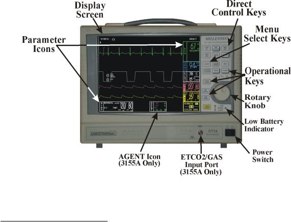
2.2 Front Panel Control Verification. (See Figure 2-1) Perform the following procedures to verify the proper operation of the Rotary Knob and Control Keys on the monitor front panel.
2.2.1 Rotary Knob Verification. The Rotary Knob is located to the right of the Display Screen under the Control Keys. This knob performs two functions: rotating (turning) this knob allows the operator to "highlight" Parameter Icon's and, while in a menu, to "highlight" menu selections; pushing this knob allows the operator to select the "highlighted" icon or menu item. Perform the following procedure to verify proper operation of the Rotary Knob:
a.Rotate the knob in the clockwise direction while verifying that the highlight moves from icon to icon with a clockwise movement.
b.Rotate the knob in the counterclockwise direction while verifying that the highlight moves from icon to icon with a counterclockwise movement.
c.With any Parameter Icon highlighted, press the knob and verify that the Parameter Menu "comes up" on the Display Screen.
d.Rotate the knob in the clockwise direction while verifying that the highlight moves from selection to selection with a top to bottom movement.
e.Rotate the knob in the counterclockwise direction while verifying that the highlight moves from selection to selection with a bottom to top movement.
2-2
f.Highlight the RETURN menu item, press the knob and verify that the menu is removed from the Display Screen.
Figure 2-1. The Millennia® 3155MVS/3155A Monitor Front Panel
2.2.2 Control Key Verification. The Control Keys are located to the right of the Display Screen. Pressing a control key will open a function menu then, with the Rotary Knob, menu items may be selected and executed within the opened menu. Perform the following procedure to verify proper operation of the Control Keys:
a.Verify the NIBP START/STOP Control Key as follows:
(1)Connect an NIBP Cuff to the SENSE and INFLATE ports on the 3150/3150M monitor Parameter Panel.
(2)Press the NIBP START/STOP Control Key on the Millennia® 3155MVS/3155A monitor.
(3)Observe that the 3150/3150M monitor attempts to take an NIBP measurement.
(4)Press the NIBP START/STOP Control Key on the Millennia® 3155MVS/3155A monitor.
(5)Observe that the 3150/3150M monitor NIBP Pressure Pump turns off.
b.Verify the NIBP STAT Control Key as follows:
(1)Press the NIBP STAT Control Key on the Millennia® 3155MVS/3155A.
(2)Observe that the 3150/3150M monitor attempts to take an NIBP measurement.
(3)Press the NIBP START/STOP Control Key on the Millennia® 3155MVS/3155A.
(4)Observe that the 3150/3150M monitor NIBP Pressure Pump turns off.
c.Verify the FREEZE Control Key as follows:
(1)Press the FREEZE Control Key.
(2)Observe that the display screen Trace A "Freezes" in Trace B location.
2-3
 Loading...