

Page 1

VERSION 3.0 QUICK REFERENCE GUIDE
Technical Support
(USA) 1-877-468-4861
International + 44 07867908926
© 2018 Invivo Corporation All Rights Reserved
4598-015-71681 Rev 1
Page 2

Please visit our Customer Resources Portal to view our complete
UroNav instructional video library.
You can create a new account on our Customer Resources Portal
through the following link: http://www.invivocorp.com/member-
registration-uronav
Once you’ve created an account, you can access the UroNav Customer
Resources Portal anytime via this following link:
http://www.invivocorp.com/customerresources/uronav
Page 3

Section 1: UroNav Pre-Procedure
Note: for detailed instructions on how to operate UroNav 3.0, please refer to the Instructions
for Use provided with your system.
1.1 Connections to Peripheral Equipment
1.2 Power ON Sequence
1.3 Shut Down - Power OFF UroNav
1.4 Import MRI data
1.5 Downloading MRI data using DynaLync (sold separately)
1.6 Patient Worklist & Schedule
• Patient Scheduling
• Timeline
• Screen layout / Icons
UroNav
Pre-Procedure
Page 4
Page1
Section 1: UroNav Pre-Procedure
Rear Panel Connections
Front Panel Connections
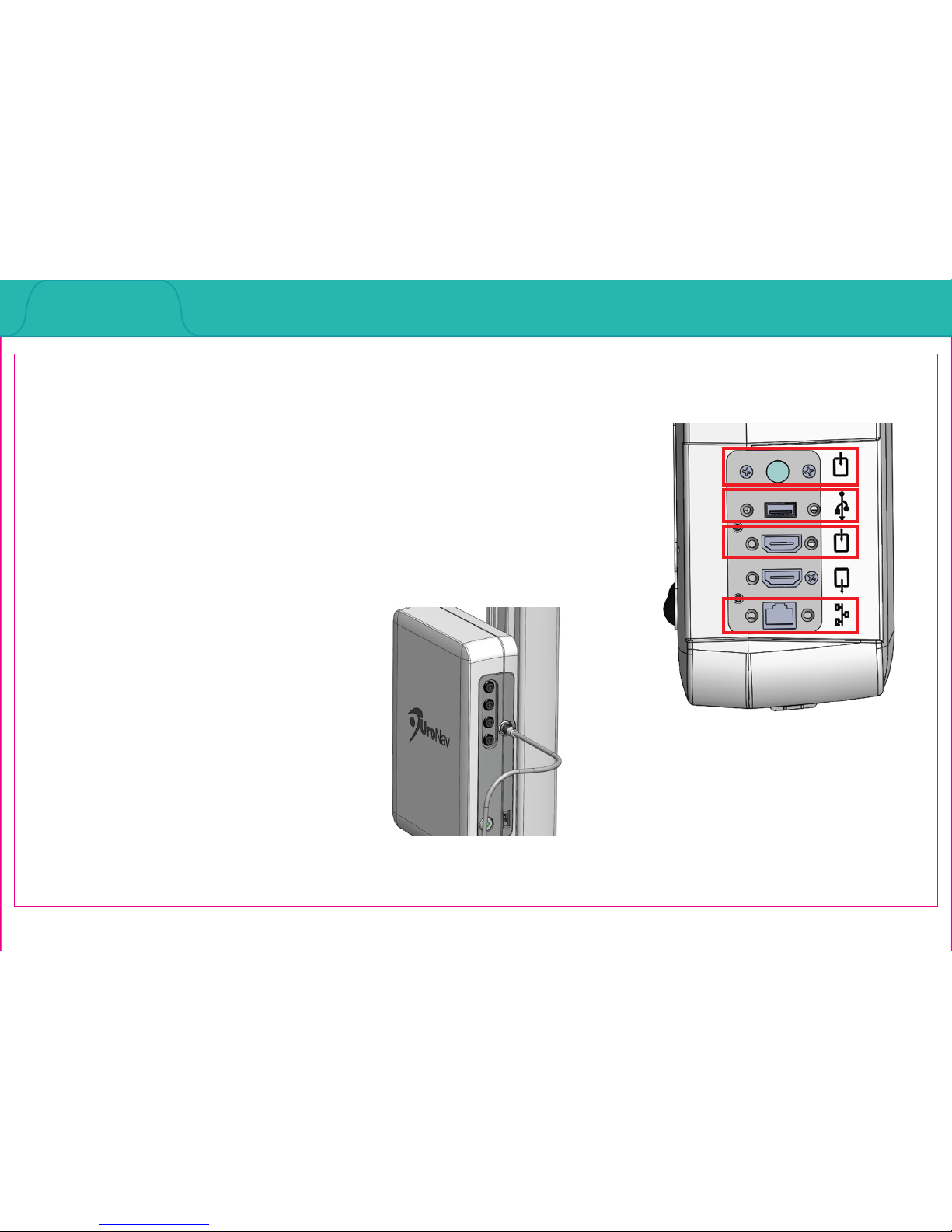
Section 1.1: Connections to Peripheral Equipment
1. Wireless: Keyboard, mouse (not pictured)
2. S-video Input: Ultrasound video input
3. USB: 3-pedal foot switch, supplied with UroNav
system, and end-user supplied portable USB
memory drives
4. HDMI Video Input: Ultrasound video input
5. RJ-45 Network Coupler: End user hospital or outpatient oce network
3
5
4
2
Page 5
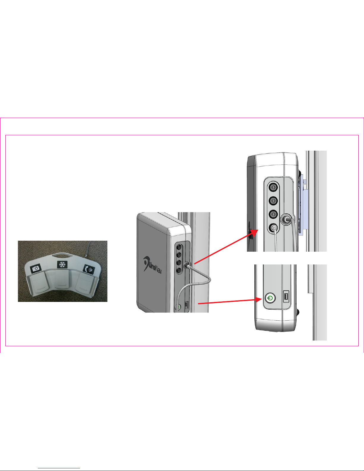
6. EM Tracker connectors x 4 (arrows on the cable connector face
forward)
7. Field Generator cable connector (red dot on the cable connector
faces forward)
8. USB: 3-pedal foot switch, supplied with UroNav system, and end-user
supplied portable USB memory drives
9. Power ON button
Front Panel Connections
Foot Pedal Switch
7
6
9
8
7
6
8
9
.
.
Page 2
Section 1.1: Connections to Peripheral Equipment (continued)
Page 6
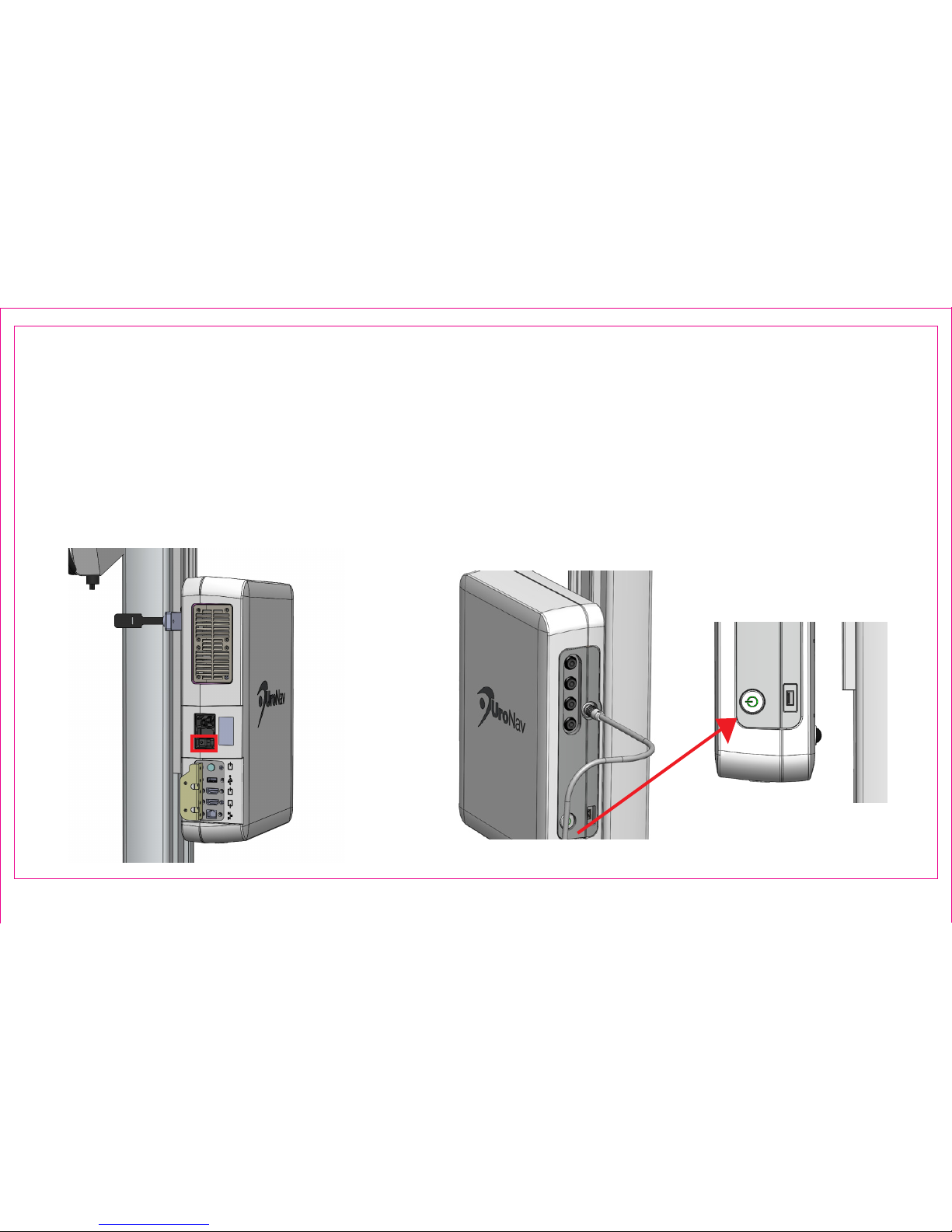
1. Connect the AC Mains cord set plug to the AC Mains source (not pictured)
2. Turn On the UroNav Fusion Biopsy System Mains power switch on the rear panel Mains AC appliance inlet
3. Press the power button on the front panel to power the system on. Green power switch LED will illuminate
4. The UroNav application will automatically launch, and the system is now ready for operation
Magnied Front View
Rear View
Page 3
Section 1.2: Power ON Sequence
3
3
2
Page 7
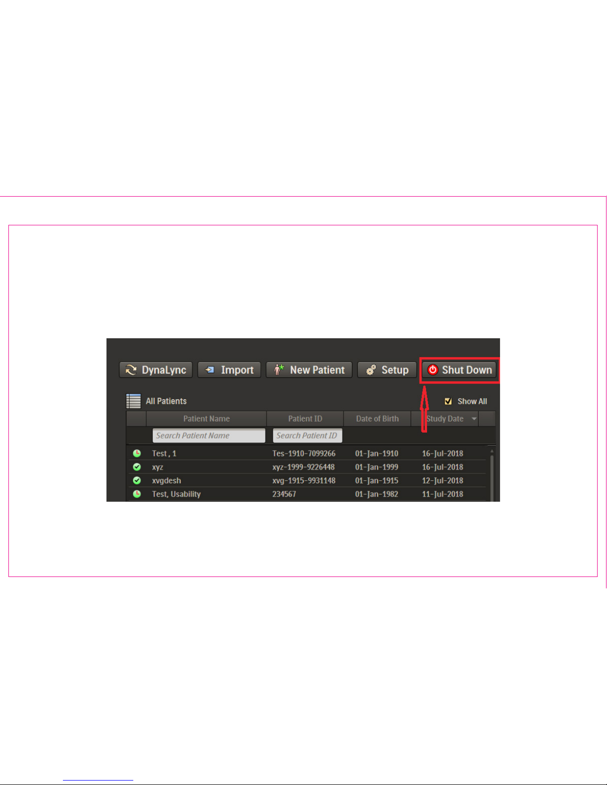
1. Press Shut Down from the Patient Browser Window
Shut Down exits the application and powers o UroNav hardware
Exit from Patient Browser
Page 4
Section 1.3: Shut Down - Power OFF UroNav
Page 8
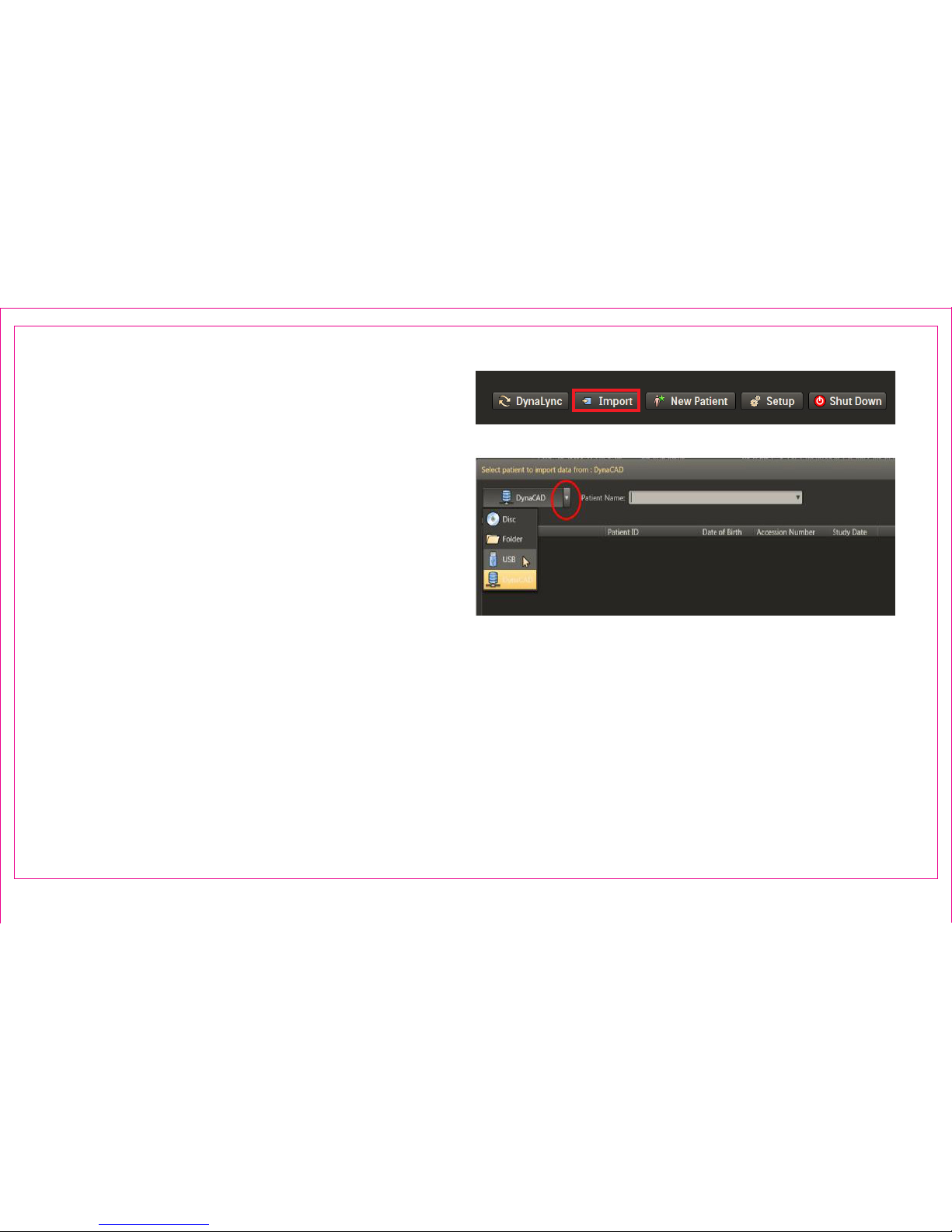
1. Press Import from the Patient Browser Window
Note: The last selected import option becomes the
default query node and automatically populates
patient names
2. Import from external media using the drop down
list
3. Patient Import will automatically retrieve three
series types:
• DCAD STL Prostate Boundary
• DCAD ROI (targets, if provided)
• High resolution T2 axial MRI
Note: It is suggested to import and view the MRI data
in advance of the procedure to verify data preparation
Import Drop Down List
Page 5
Section 1.4: Import MRI Data
2
1
Page 9
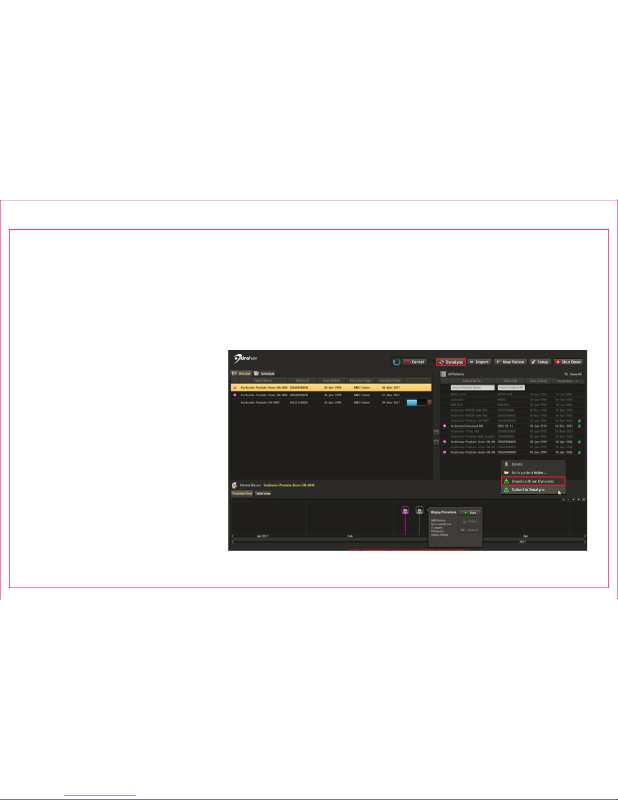
*DynaLync Prostate is an optional feature, sold separately
1. Press DynaLync from Patient Browser Window
a. Automatic download of MRI data for all procedures scheduled in DynaLync for the current day
b. Manual download MRI data with the Show All lter
i. “Dimmed” entries represent the DynaLync patient database only
ii. “Bright” entries result from
successful download onto
UroNav
2. Right-click on patient entry, select
Download from DynaLync from
the context menu
3. Patient Import will retrieve three
series types:
a. DCAD STL Prostate Boundary
b. DCAD ROI (targets, if provided)
c. High resolution T2 axial MRI
Page 6
Section 1.5: Download MRI Data from DynaLync Server
1
2
Page 10
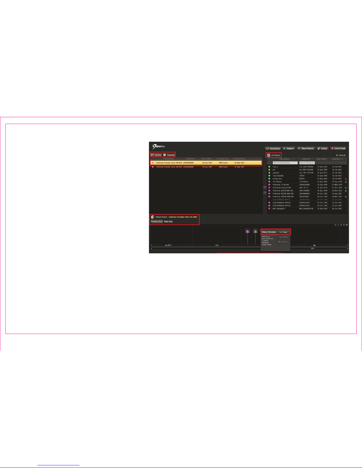
1. Select patient study from the All Patient
List
2. Move patient into a Schedule or active
Worklist
Preview or Begin a New Procedure:
3. Select patient from Worklist
4. Select study from chronological Patient
History Timeline
5. Click Start to proceed to Review
Segmentation and Targets Screen
Patient Worklist & Timeline
Page 7
Section 1.6: Patient Worklist – Schedule – Timeline
3
2
1
4
5
Page 11
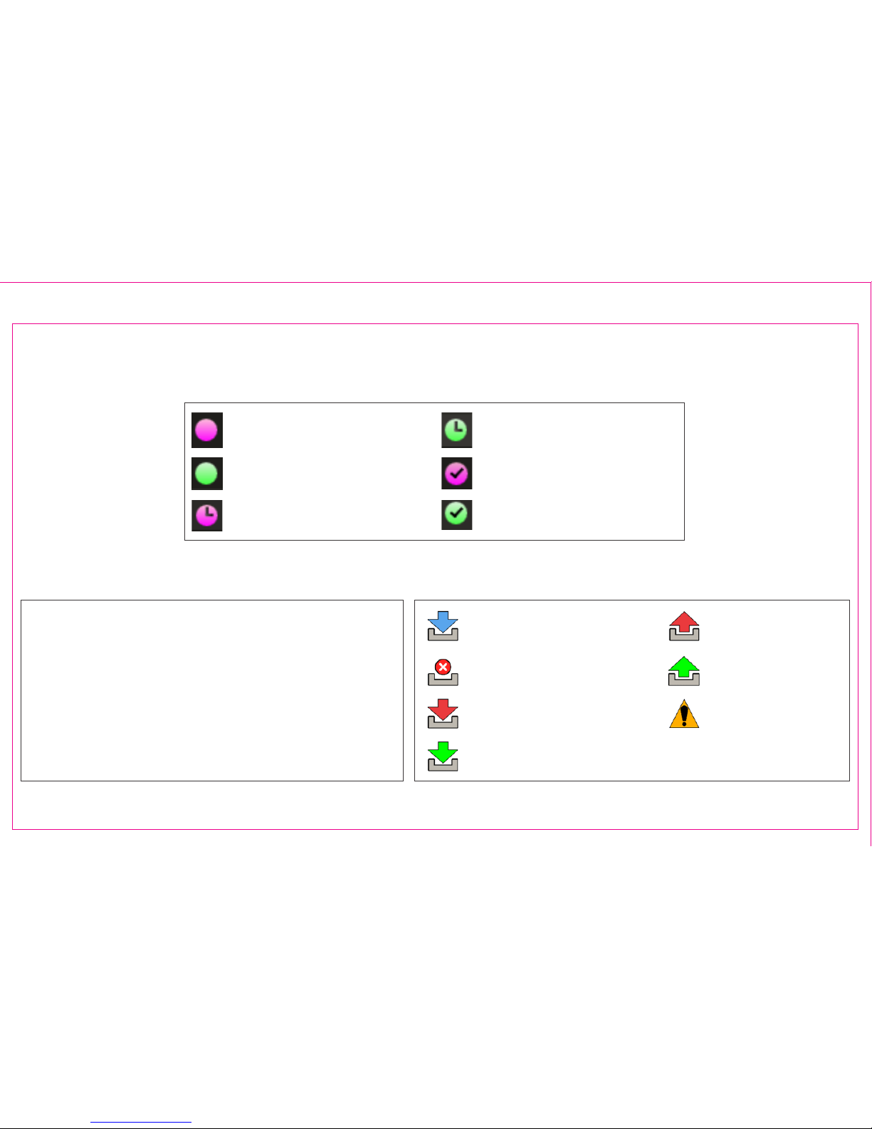
Delete: Deletes the patient data from the UroNav
system.
Go to patient folder: Takes the user directly to the
folder storing the patient’s procedure data.
Download from DynaLync: Transfers patient procedure
data from DynaLync Prostate to UroNav.
Upload to DynaLync: Transfers patient procedure data
from UroNav to DynaLync Prostate.
Procedure Status Icons for DynaLync (sold separately)
Procedure Status Icons (Note: Not all shown)
Download in Progress
Download Failed
Upload Failed
Upload Completed
Upload Not Ready
Download Completed
Download Cancelled
Right Click Context Menu Options
Page 8
Section 1.6: Patient Worklist – Schedule – Timeline (Continued)
MRI Fusion Patient Ready
U/S Only Patient Ready
MRI Fusion Biopsy Procedure
(Scheduled)
U/S Only Biopsy Procedure
(Scheduled)
MRI Fusion Biopsy Procedure
(Biopsied)
U/S Only Biopsy Procedure
(Biopsied)
Page 12

UroNav
Intra-Procedure
Section 2: UroNav Intra-Procedure
2.1 Review Segmentation & Targets Screen
2.2 Tool Setup/Field Generator Positioning
2.3 TRUS Sweep & 3D Segmentation
• Start/Stop – Side/End Fire probes
• Edit 3D Segmentation
• Anatomical Landmarking
• Segmentation Edit Commands
2.4 Registration – Align US Volume with MR
• Edit Fusion Overlay
• Elastic Deformation
2.5 Biopsy Navigation – Rotational
Adjustment*
*End-re TRUS probe only
2.6 Transrectal Biopsy Targeting Procedure
Steps
1. Navigate to Targets / Maintain Anatomical
Alignment
2. Activate Target from list for viewing
3. Target Icon Appearance
4. Use color-coded guidance bars to locate
target
5. Advance needle when target intersects
biopsy needle guideline
6. Press Freeze after sample is taken
Scroll to visualize needle tip to record biopsy location
7. Double Click to mark needle tip location
8. Press Add to date stamp and associate
the location to the current target and
resume real-time, cine imaging
9. Repeat for subsequent targets or
Systematic Regions
10. Post Procedure Screenshots, Export,
Shutdown
Overview of Transrectal Targeting Steps
Page 13
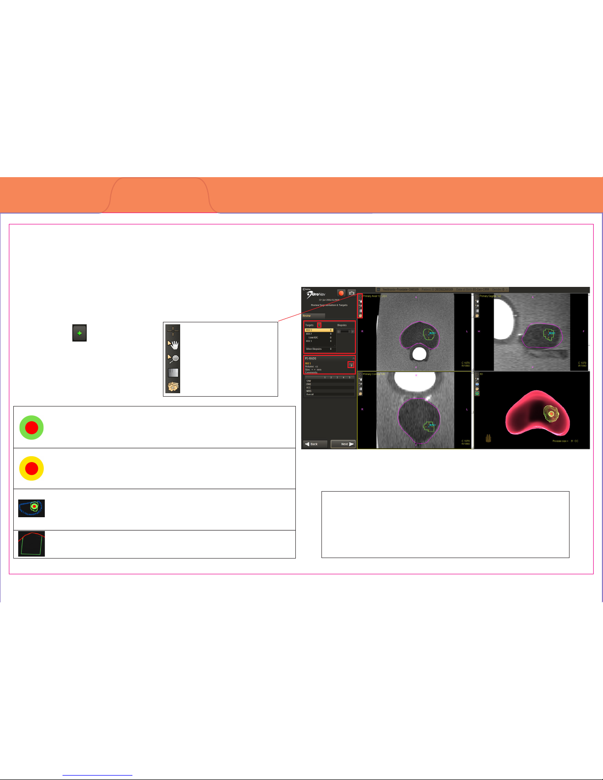
Rename: Allows changes to a selected target label.
Delete: Removes selected target.
PI-RADS: Displays Prostate Imaging Reporting and
Data System information for the selected target.
Right Click Context Menu Options
MRI-imported target
Note: The bull’s-eye for MRI-imported targets represents
the calculated center of the identied target
Manually-added target
Note: Manually added targets are visually distinct from
imported targets
MRI-imported sub-region
Note: A sub-region target is drawn in relation to the
parent target (blue)
Systematic plan region
Note: Systematic plan regions do not include a bull’s-eye
Section 2.1: Review Segmentation & Targets Screen
Section 2: UroNav Intra-Procedure
Page 9
Preview MRI-dened prostate boundary and biopsy targets in Tri-planar MRI format
1. Image Action Icons
2. MRI-dened Target and
Biopsy list or Add New
Targets
3. PI-RADS Target
Metadata
4. Target Identication
3
2
1
4
Mouse pointer
Pan image
Zoom the image
Auto Window & Level
Show/Hide all targets
Page 14
Page 10
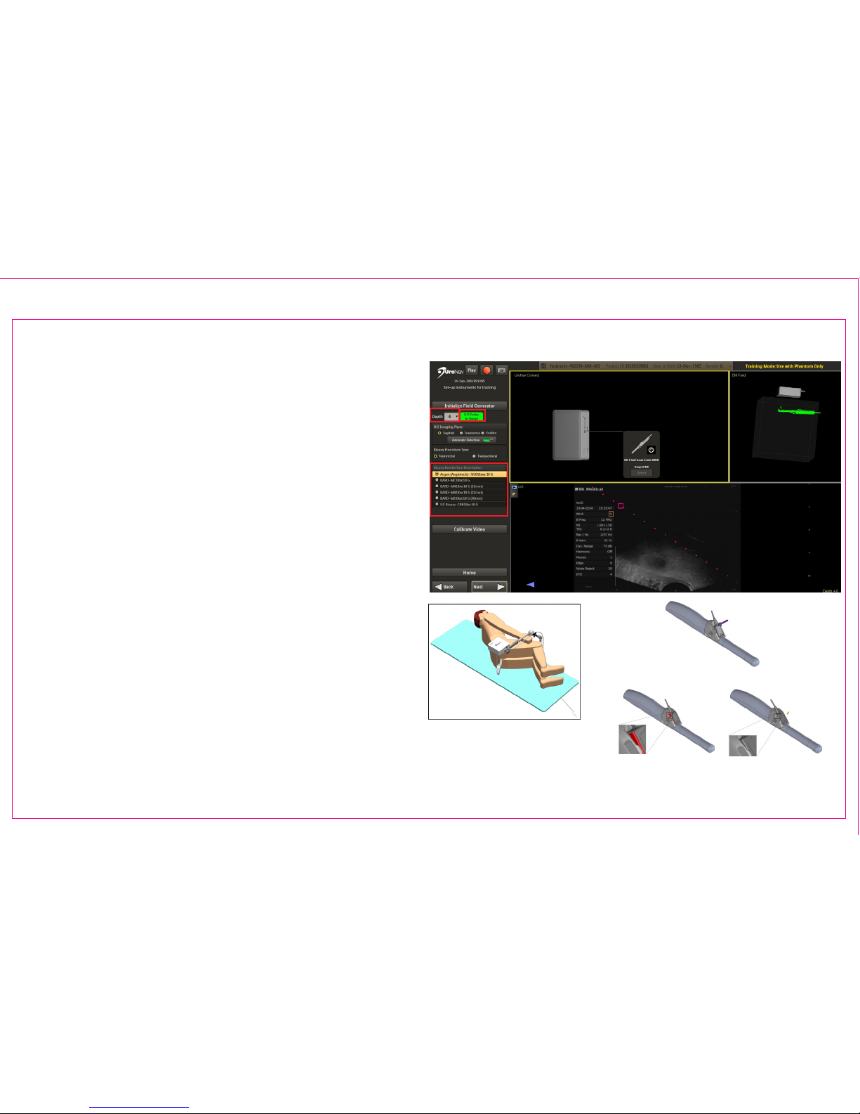
Section 2.2: Tool Setup / Field Generator Positioning
Initialize Navigation Tools to create Electromagnetic
(EM) Field for Fusion Registration, Targeting, and
Recording Biopsy Core Samples
1. Match Depth on UroNav to Depth Display on US
2. Conrm Biopsy Needle/Gun
3. Verify FG Tracker Connection, US Model and
Probe Selection
4. EM Tracker Status
A. The color represents the range found
within the generated EM eld
B. Green color shows tracking “In Range”
5. Verify live US Video feed and Biopsy Needle
Trajectory
3
2
4
1
5
Position FG directly
over tracking device(s)
following US probe
insertion
Attach Tracker to Probe Holder
Apply Force Until Flush
*TRUS probe and holder may vary
Note: See Section 5: UroNav Supported Supplies
of this document for list of US models, probes and
biopsy supplies compatible with UroNav.
4
Page 15
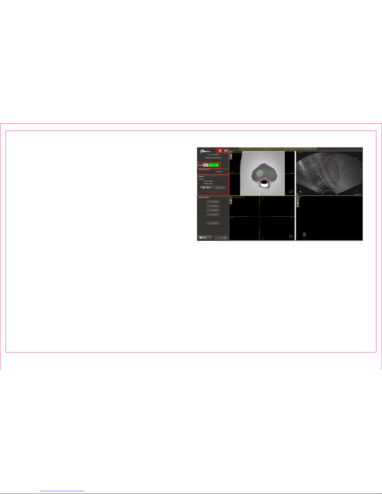
Acquire US Sweep to Reconstruct a 3D Model of the
Prostate
1. Recording Commands
2. TRUS Information / EM Tracker Status and Depth
Selection
3. Ultrasound Imaging Plane
4. Sweep Commands
A. Alternatively, the 3-pedal foot switch
may be used.
i. Press the Start button or depress
and hold the Sweep Pedal on the
supplied 3-pedal foot switch to
begin collecting ultrasound images
of the prostate gland
ii. Press the Stop button or lift the foot
o the Sweep Pedal to halt image
collection and allow for 3D
reconstruction
The sweep is best performed as a smooth, steady
motion, applying constant pressure. Sweeps of the
gland are supported with the patient in the left
decubitus, right decubitus, or lithotomy positions.
For end-re TRUS: Sweep transversely from base to
apex (or apex to base) of the prostate without rotation
and keeping the needle guide upward, closest to the FG.
For side-re TRUS: Sweep in the sagittal view and
completely from one side of the prostate to the other.
Alternatively, the sweep can be performed in the
transverse plane, perpendicular to the gland, from the
base to apex, or apex to base.
Page 11
Section 2.3: TRUS Sweep and 3D Segmentation
1
3
2
4
Page 16
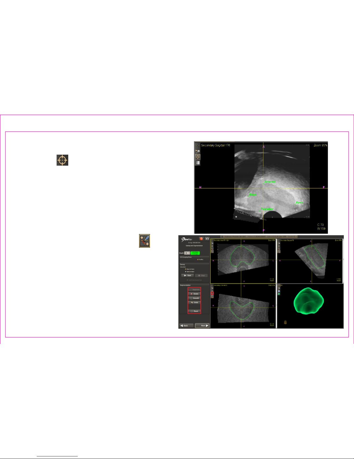
Following a sweep, the default Anatomical Fiducial
Landmark Tool allows as many as six axis
endpoints be placed to support 3D reconstruction.
Segmentation Action Commands to Edit 3D Boundary:
1. Press Segment button to complete segmentation
and view 3D rendering
2. Modify boundary by clicking Action Commands
or, by dragging the left mouse button using the
default Adjust Mesh US Boundary Tool in any
viewport
Page 12
Section 2.3: TRUS Sweep & 3D Segmentation (continued)
1
2
Page 17
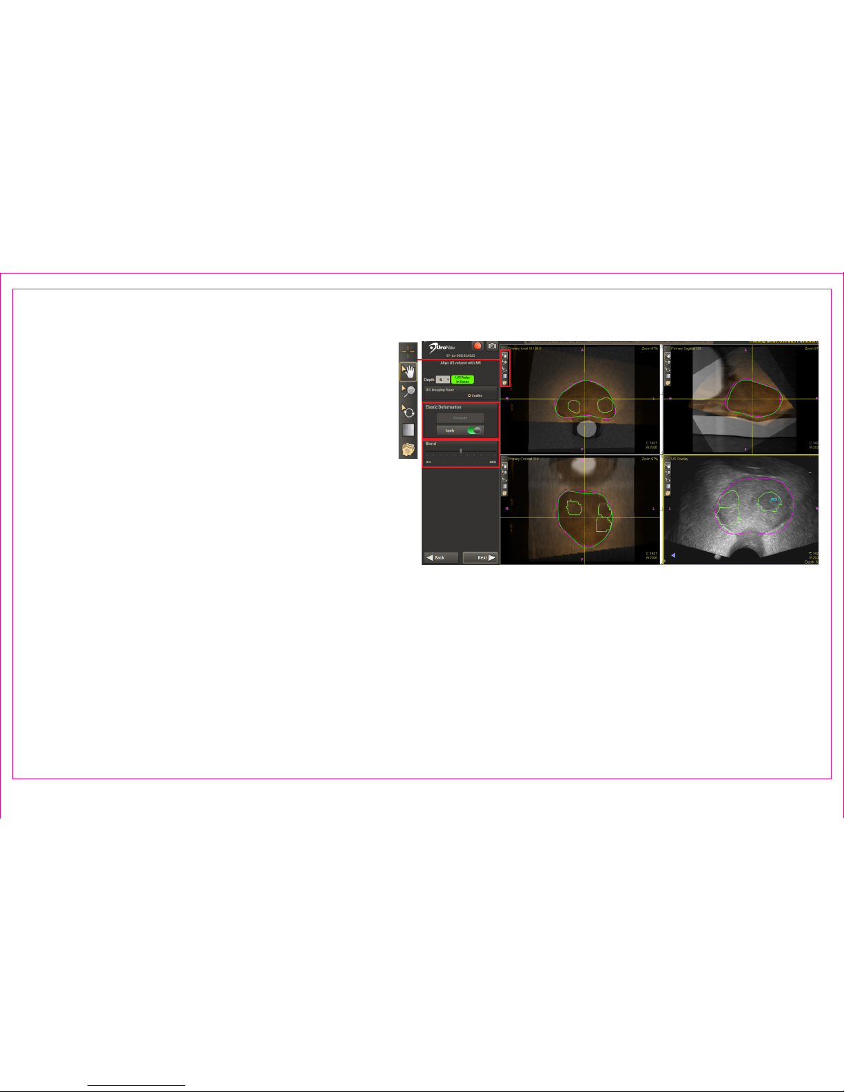
A semi-automatic 3D rigid registration is applied to
both volumes. Align and superimpose the green US
prostate boundary with the magenta MR prostate
boundary using anatomical landmarks.
1. Image Action Commands
• Manually complete registration through pan,
zoom, and rotation tools
• Conrm complete alignment using multiple
anatomical landmarks in at least two planes
Verify depth setting selection when switching
imaging planes with multi-planar US probes.
2. Elastic Deformation (toggle)
• Compute Elastic Deformation only after initial, rigid registration alignment
• Based on segmentation results, Elastic Deformation maps the MR volume elastically to the US volume
3. Multi-Modality Blend Tool adjusts blending superimposition for optimal visualization
Page 13
Section 2.4: Registration - Align US Volume with MR
1
2
3
Page 18
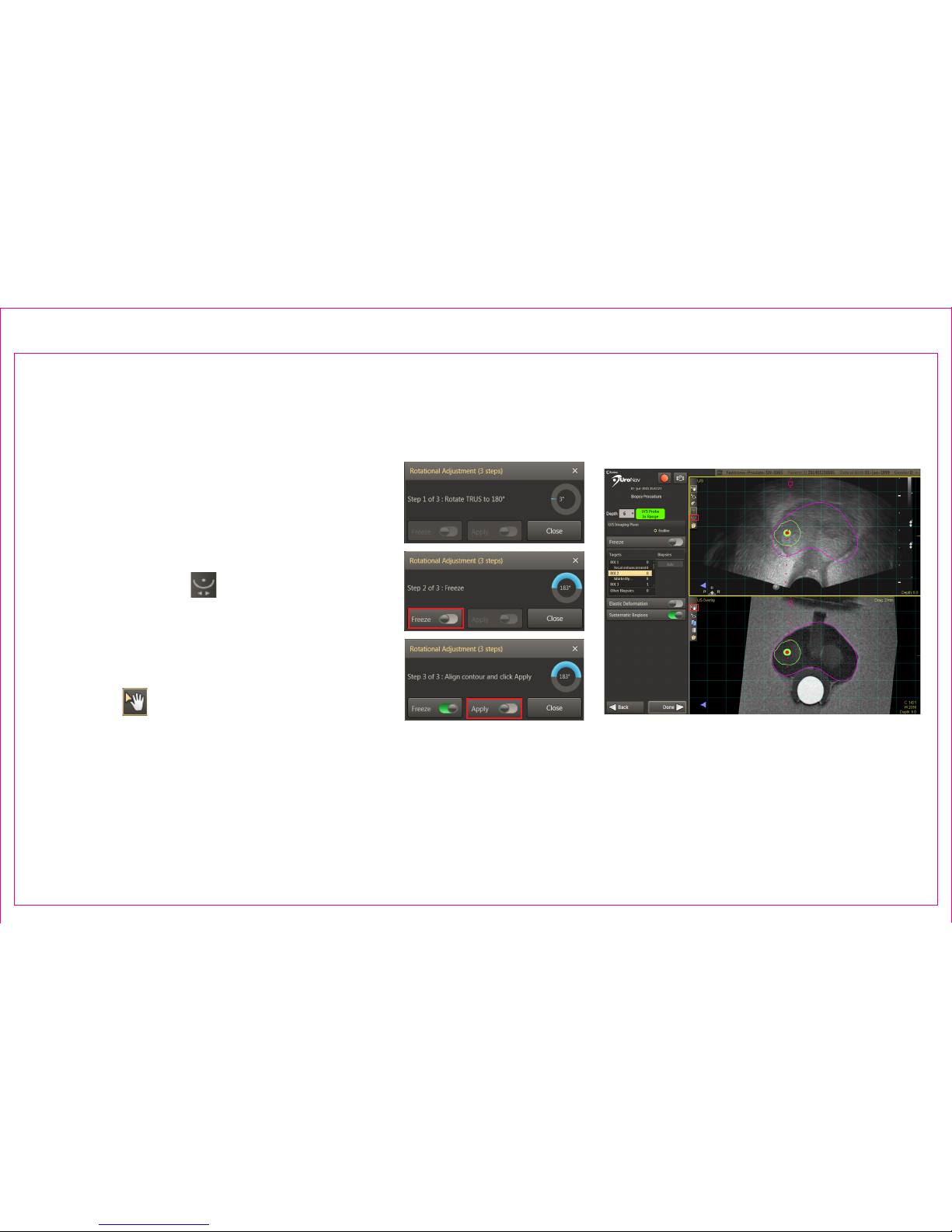
*(end-re US TRUS probe only)
Fine tune the initial registration for possible
variances in the apex location after rotating
the probe 180° from the original sweep
orientation.
1. Select Rotational Adjustment icon in the
top left viewport
2. Follow screen prompts to rotate the
TRUS probe 180± 5° from original sweep
position
3. When indicated, press Freeze
4. Use Pan from the MR view (bottom
panel) to align the magenta contour
with the live, U/S view (top panel). Press
Apply.
Page 14
Section 2.5: Biopsy Navigation – Rotational Adjustment
2
3
4
4
1
Page 19
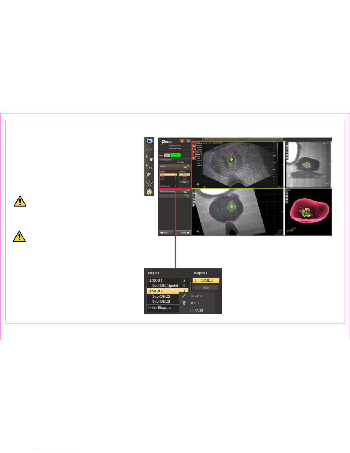
Navigation Guidance to Pre-Dened Targets
and Anatomical Alignment Maintenance
1. Image Action Commands within any
2D viewport realign the anatomical
landmarks of the magenta MR boundary
to be in line with the US image
Maintaining alignment is necessary
throughout the procedure and may
require multiple adjustments
Failure to successfully align the US
with the MRI requires returning to the
Sweep and Segmentation screen
2. Targets and Biopsies List / PI-RADS
Metadata
Right Click for a Context Menu to:
• Delete / Rename biopsy
• View PI-RADS (if available)
• Add to record a screenshot of biopsy
location
Page 15
Section 2.6: Transrectal Biopsy Procedure
1
2
Page 20
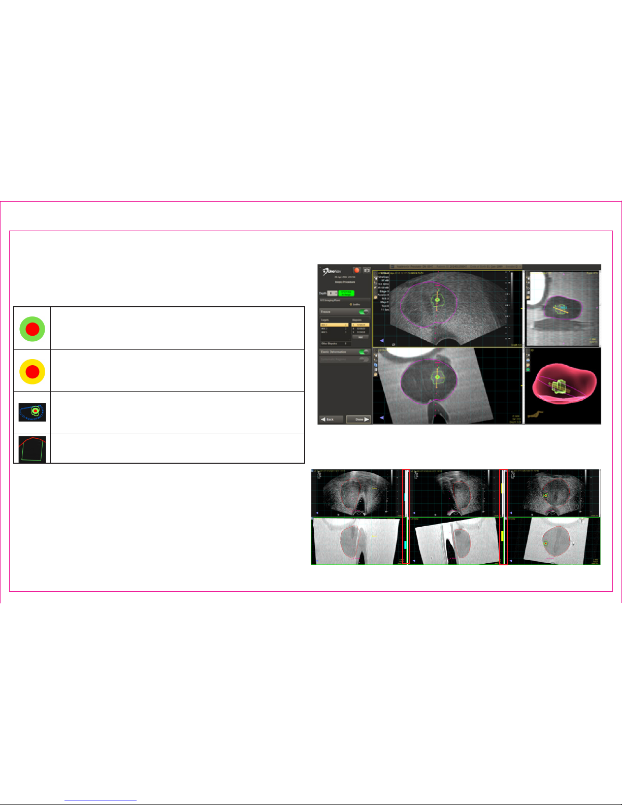
Locate pre-dened targets
3. Biopsy Procedure: Target Icon Appearance
MRI-imported target
Note: The bull’s-eye for MRI-imported targets represents
the calculated center of the identied target
Manually-added target
Note: Manually added targets are visually distinct from
imported targets
MRI-imported sub-region
Note: A sub-region target is drawn in relation to the
parent target (blue)
Systematic plan region
Note: Systematic plan regions do not include a bull’s-eye
4. Color-coded guidance bars (blue/yellow) assist to
navigate to the selected target
Page 16
Section 2.6: Transrectal Biopsy Procedure (continued)
2
3
4
Page 21
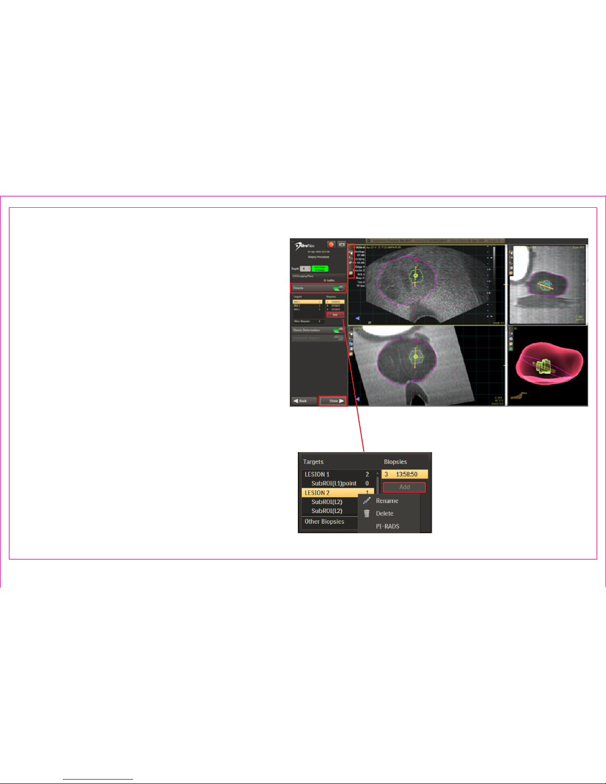
Section 2.6: Transrectal Biopsy Procedure (continued)
Acquiring a Biopsy Sample
5. Ensure the biopsy guideline intersects the
target
• Advance the needle / Monitor needle
trajectory
6. After the biopsy sample is taken, select
Freeze or depress/release the foot pedal to
interrupt real-time, cine viewing
• Scroll through the US frames to where
the distal tip of the biopsy needle is
visualized
7. Double Click to mark the distal tip
8. Press Add to automatically record a
screen capture of the biopsy location and
associate it with the current target and
resume real-time, cine viewing
9. Repeat alignment registration for
additional samples or select next lesion
and proceed to navigate
10. Press Done when complete
Page 17
5
6
8
10
Page 22

Section 3: Post-Procedure/Support
3.1 Post Procedure Overview and Exporting DICOM Data
3.2 Uploading Procedure Data to DynaLync Server (sold separately)
3.3 UroNav Data Backup
3.4 UroNav Service Support
3.5 Customer Resources Portal
3.6 Shut Down - Power OFF UroNav
UroNav Post-
Procedure/Support
Page 23
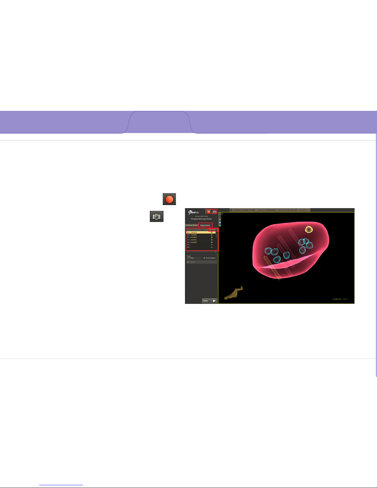
Section 3: Post-Procedure/Support
Section 3.1: Post Procedure Overview and Exporting DICOM Data
Page 18
1
4
3
2
The 3D image can be zoomed and examined from
multiple viewpoints
1. Recording Commands
• Video Recording - Start/Stop acquiring
Mp4-formatted video recording
• Acquire Additional Screen Captures
2. Images Review displays all targets and associated
biopsies in 2D tri-planar MRI format
3. Target List includes screen captures collected
during the current procedure
• Each biopsy has a corresponding screen
capture
4. The Export checkbox identies screen captures to
be exported
• Select Export to choose a predened
DICOM destination
Page 24
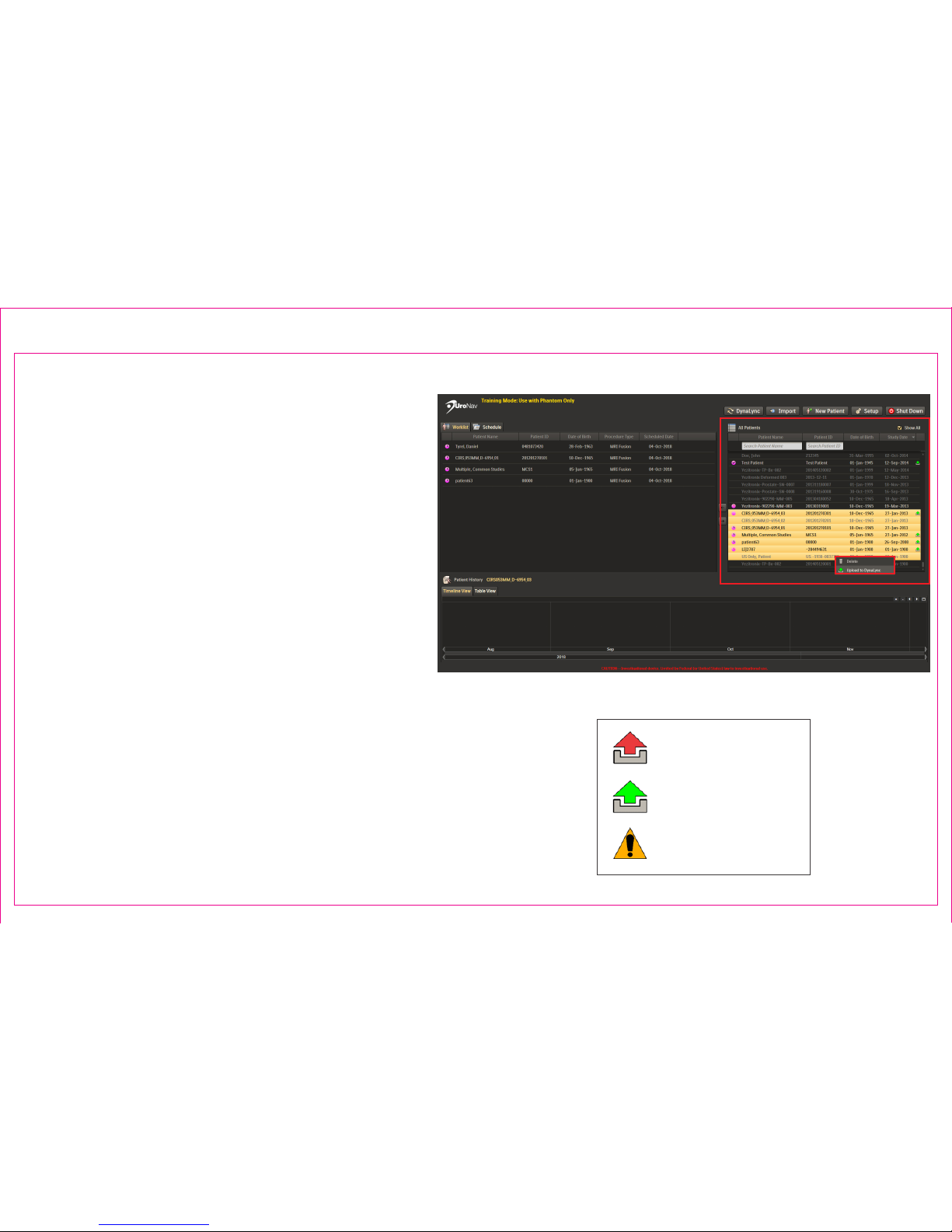
*DynaLync Prostate is an optional feature, sold
separately
Upload procedure data to the DynaLync Prostate
system for permanent storage, and subsequent
removal from the UroNav computer.
If connected to the network, data will be
uploaded automatically to DynaLync following
each procedure.
To manually transfer all biopsy data:
1. Select patient(s) from the All Patients list
2. Right Click to Upload to DynaLync
Upload Status Icons
Upload Failed
Upload Completed
Upload Not Ready
Page 19
Section 3.2: Uploading Procedure Data to DynaLync Server
1
2
Page 25
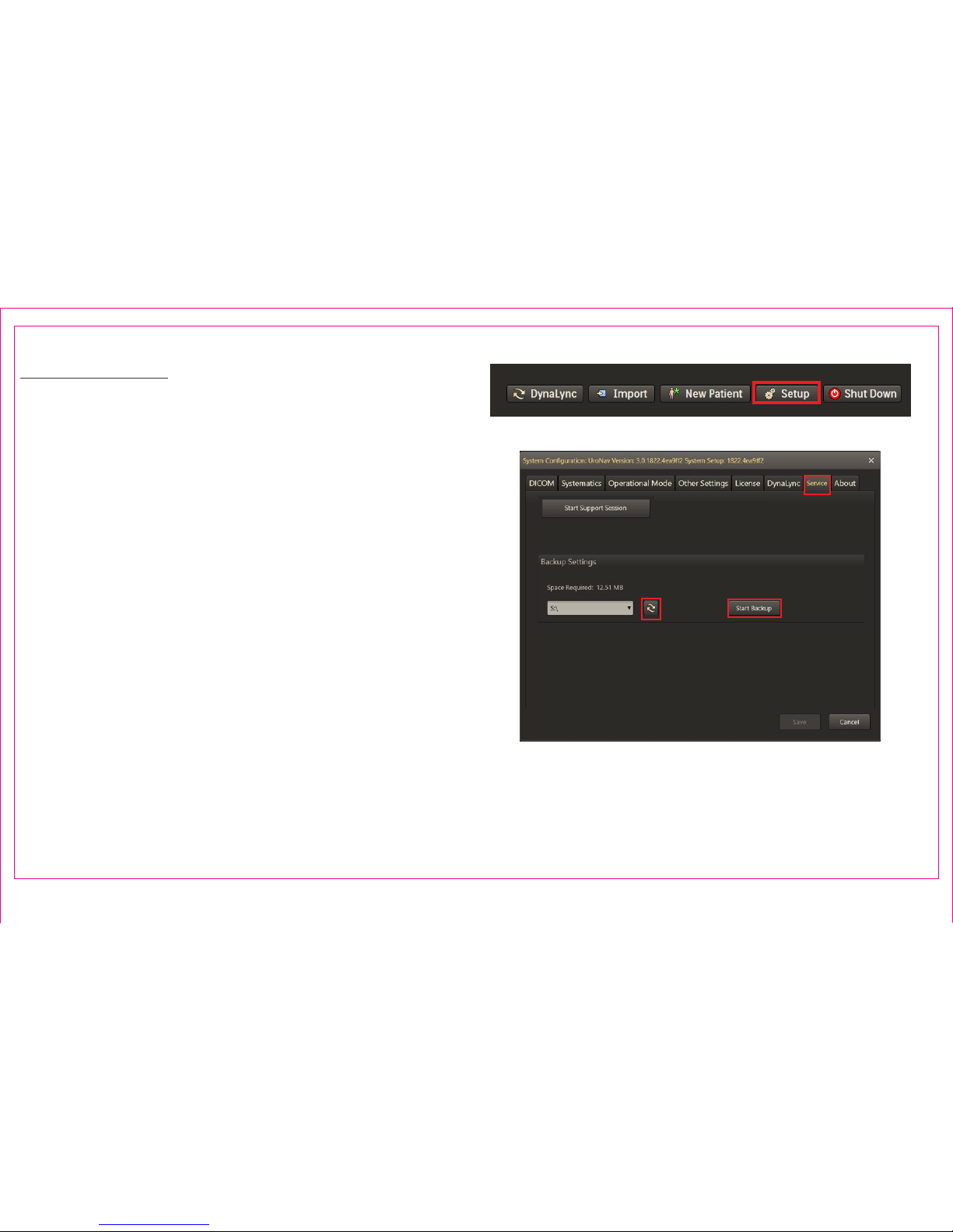
Backup Overview:
1. Select Setup from the main browser menu
2. Select the Service tab
3. Click the Start Backup button to backup UroNav data
to the selected external drive. Backup operation is
indicated by a progress bar. Once complete, UroNav
data is available in the external media.
4. Click the Refresh button to refresh the available
external drives in the dropdown list.
1
Page 20
2
34
Section 3.3: UroNav Data Backup
Page 26
Page 21
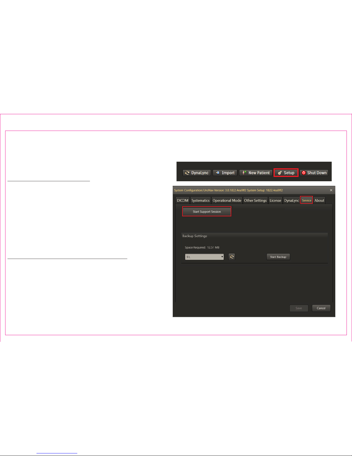
The UroNav system can be connected remotely with a service representative via a support session. Support
sessions require a live network connection.
To Start a Support Session:
1. Select Setup from the main browser menu
2. Select the Service tab
3. Select Start Support Session to establish a remote
connection to a service representative. The service
representative will need to validate credentials to
gain access to UroNav.
Technical Support Contact Information:
email: [email protected]
Phone: (USA) 1-877-468-4861
Phone: (International) + 44 07867908926
2
3
Section 3.4: UroNav Service Support
1
Page 27
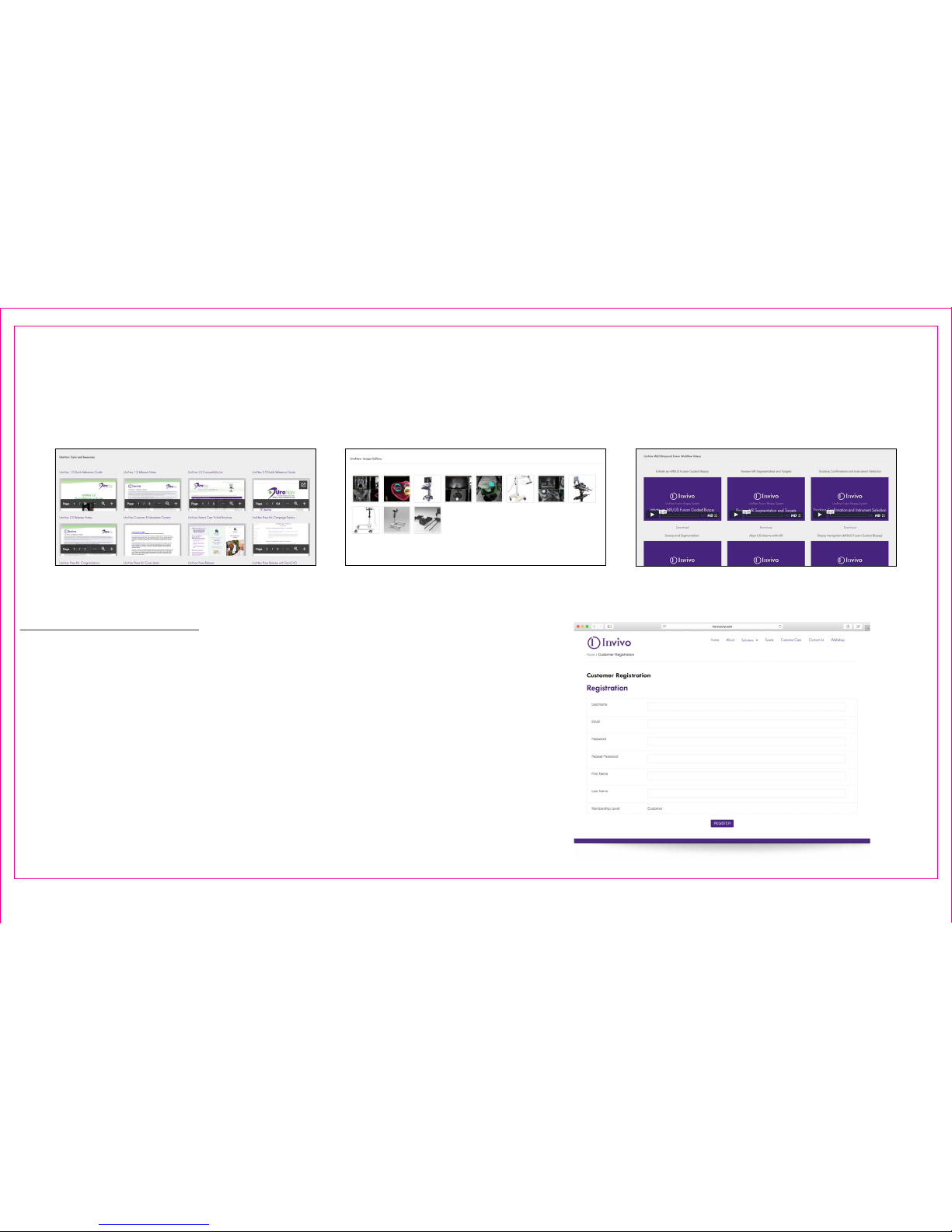
Please visit our Customer Resources Portal to view instructional video libraries, image galleries, and written
resources for UroNav.
To Create an Account:
1. You can create a new account on our Customer
Resources Portal via the following link: http://www.
invivocorp.com/customer-registration/
2. Once you have created an account, you can access
the Customer Resources Portal anytime via
the following link: http://www.invivocorp.com/
customerresources/
Written Resources Image Gallery Video Library
Section 3.5: Customer Resources Portal
Page 22
Page 28
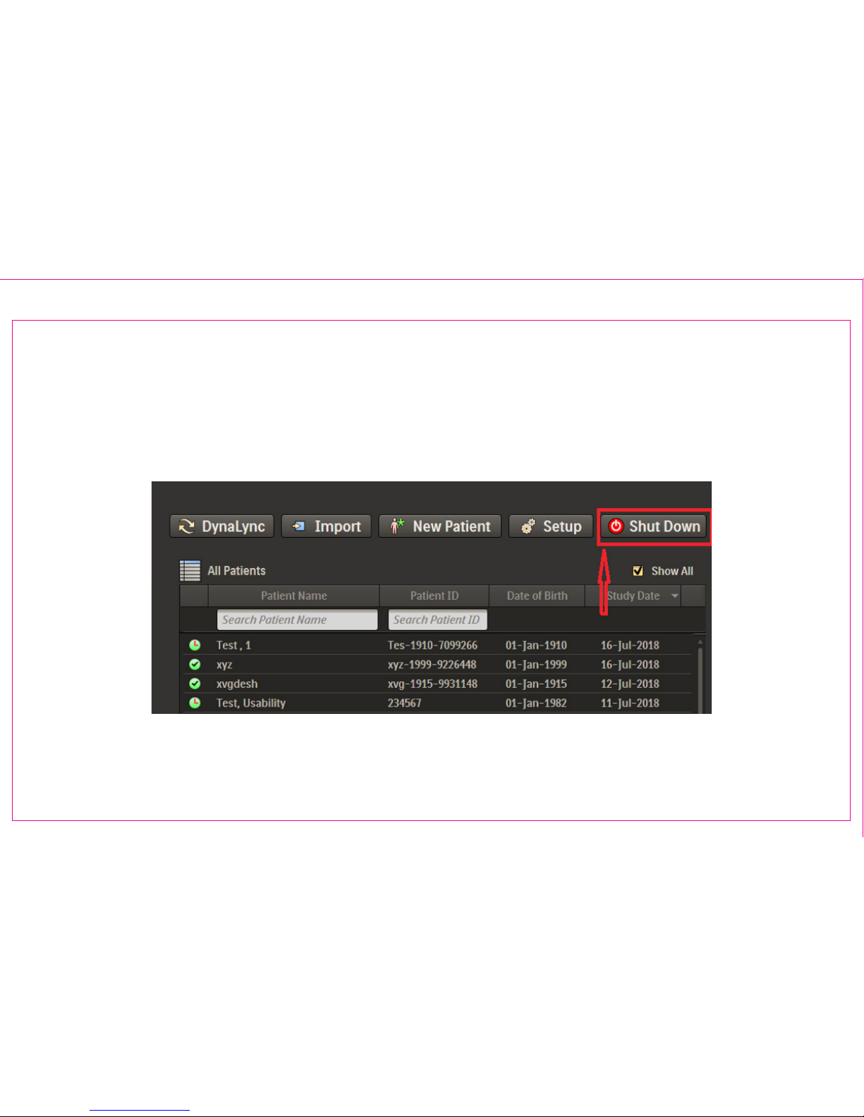
1. Press Shut Down from the Patient Browser Window
Shut Down exits the application and powers o UroNav hardware
Exit from Patient Browser
Page 23
Section 3.6: Shut Down - Power OFF UroNav
Page 29

Section 4: UroNav Tips & Cleaning
4.1 UroNav Keyboard Shortcuts
4.2 DynaCAD to UroNav Data Preparation
4.3 MR Scan Recommendations
4.4 Cleaning Overview
UroNav Tips &
Cleaning
Page 30

Page 24
Section 4.1: UroNav Keyboard Shortcuts
Section 4: UroNav Tips & Cleaning
Key Stroke Function Workow Context
F12 Toggle patient information bar visible/hidden N/A
V Display prostate volume information 2D viewport
Cursor Keys Pan U/S registration, small step U/S-MR blended viewports
Shift + Cursor Keys Pan U/S registration, large step U/S-MR blended viewports
Right-Mouse Drag Adjust window/level values U/S-MR blended viewports
Mouse Wheel Scroll through image frames/slices/cine Sweep, MR volume, cine
PgUp/PgDn Scroll through images frames/slices Sweep, MR volume
Left-Mouse Drag Add segmentation points Sweep and Segmentation, U/S
Right-Mouse Drag Erase segmentation points Sweep and Segmentation, U/S
G Toggle needle guideline Biopsy Procedure, US Viewport
Mouse Wheel Reposition needle guideline depth cursor Biopsy Procedure (Freeze Mode)
Left-Mouse Click Reposition needle guideline depth cursor Biopsy Procedure (Freeze Mode)
Left-Mouse Drag Reposition needle guideline depth cursor Biopsy Procedure (Freeze Mode)
Left-Mouse
Double-Click
Place needle tip marker o of needle
guideline and reposition depth cursor
Biopsy Procedure (Freeze Mode)
Q Toggle uniform grid overlay On/O Biopsy Procedure
ALT-F Applies a horizontal ipping transformation
to the ultrasound coordinate system
Setup, Sweep Biopsy Procedure
Page 31

Page 25
Section 4.2: DynaCAD to UroNav Data
Preparation
Section 4.3: MR Scan Recommendations
The following steps should be followed on DynaCAD to
ensure proper data preparation for use with UroNav:
1. Congure DynaCAD to automatically calculate the
gland segmentation using the recommended T2W
Axial High Resolution images.
2. Optimize the gland segmentation on the T2 and
approve it using the Approve button.
3. Draw 2D or 3D (preferred) ROIs for each target associated with T2W Axial High Resolution images. Create
additional sub ROI targets if desired.
4. Characterize the ROIs / targets using the PI-RADS
menu.
5. Save all the target results using the Save All
button.
6. Select the following series to export DynaCAD data
to an external media device or network DICOM
connection
- T2W Axial high resolution series
- DynaCAD STL Prostate Boundary series
- DynaCAD ROI Series
T2W Axial High Resolution
Slice coverage from bladder to pubis, with slices
angled perpendicular to the prostate/rectal
plane.
Fast/Turbo Spin Echo
2D or 3D Acquisition
Thickness ≤ 3mm
Gap 0mm
Slice Spacing ≤ 3mm
FOV ≤ 20cm
Voxel Size 1x1x3mm
Averages 2
Page 32
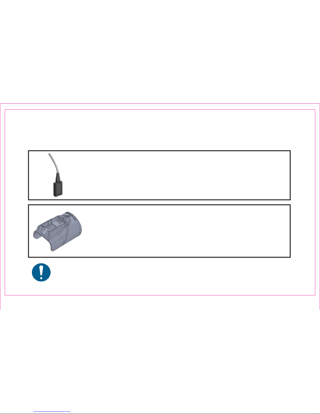
EM Tracker
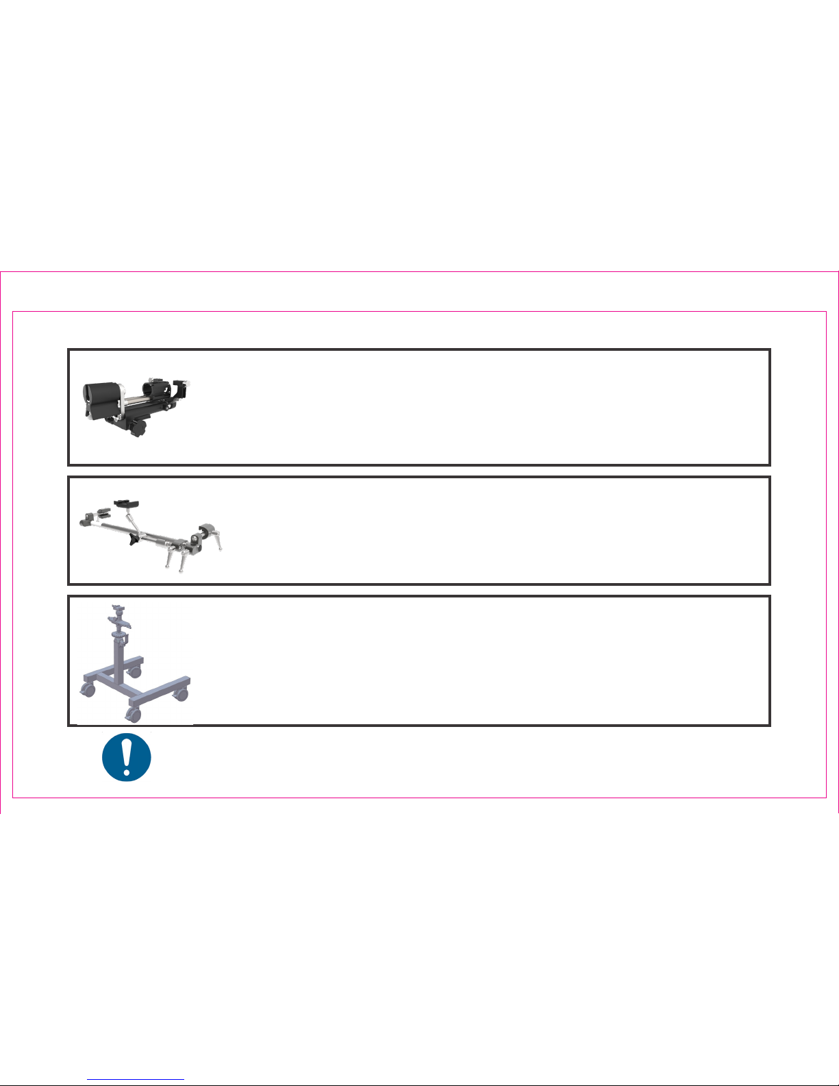
Refer to the "Cleaning and Disinfection of the UroNav EM Tracker"
Section of the UroNav Instructions for Use provided with your
system.
Refer to the Instructions for Use for detailed cleaning instructions.
• Users are responsible to provide the highest degree of infection control to patients, co-workers, and
themselves.
• Follow all infection control policies established by your facility to avoid cross-contamination.
EM Tracker Probe Holder
Refer to the "Cleaning of the disposable EM Tracker Probe Holder
before use" Section of the UroNav Instructions for Use provided with
your system.
Page 26
Section 4.4: Cleaning Overview
Page 33
Page 27
Refer to the Instructions for Use for detailed cleaning instructions.
Section 4.4: Cleaning Overview (Continued)
Stepper
Refer to the "Cleaning of the Stepper" Section of the UroNav Instructions
for Use provided with your system.
Stepper Stand
Refer to the "Cleaning of the Stepper Stand" Section of the UroNav
Instructions for Use provided with your system.
Stepper Arm
Refer to the "Cleaning of the Stepper Arm" Section of the UroNav
Instructions for Use provided with your system.
Page 34

Section 5: Supported Supplies
5.1 Probe Holder Attachment
5.2 Supported Biopsy Guns & Needles for Transrectal Procedures
5.3 Supported Biopsy Guns & Needles for Transperineal Procedures
UroNav Supported
Supplies
Page 35
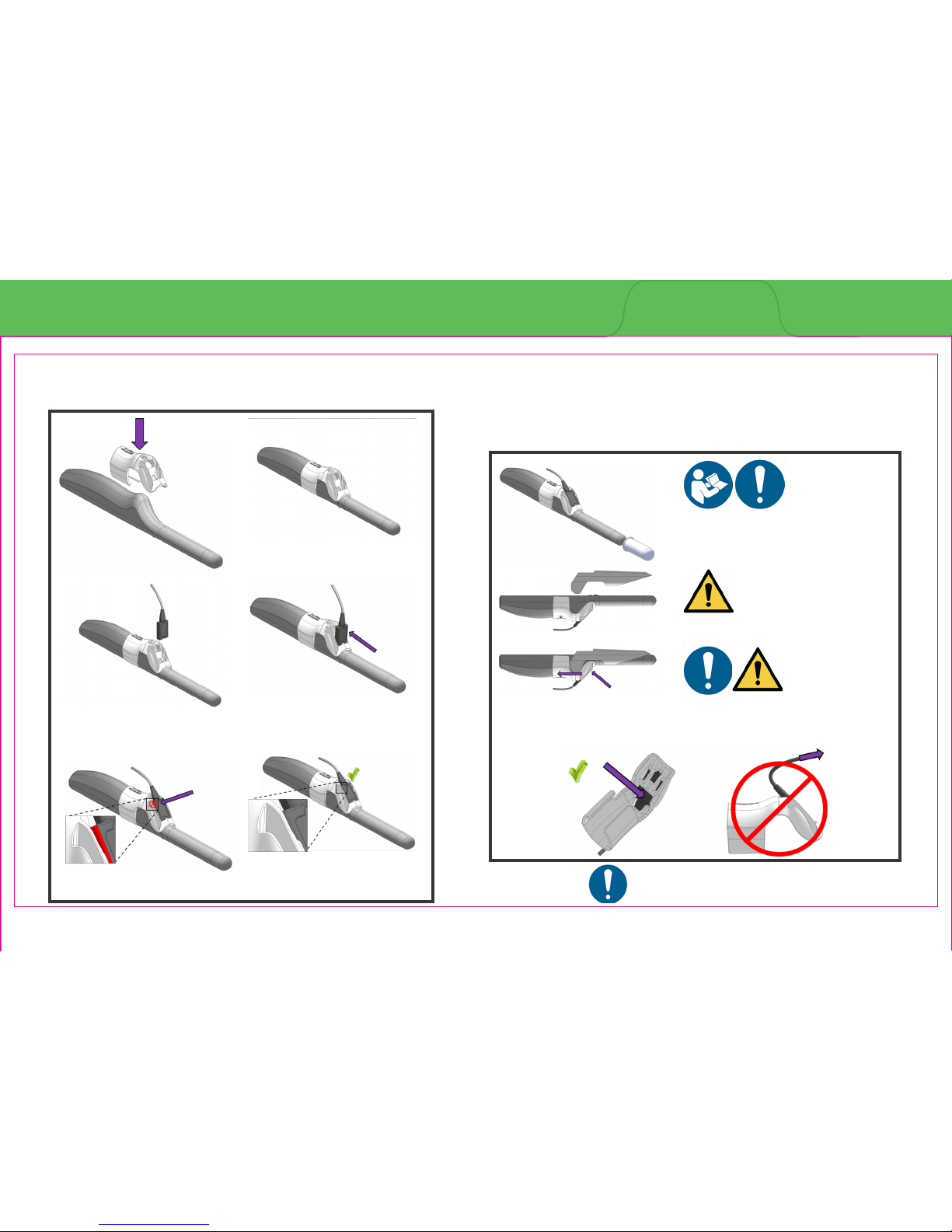
*TRUS probe make/model and probe holder may vary.
Please refer to the UroNav Instructions for Use (Section
C) for probe holder installation instructions specic to
your compatible TRUS probe.
Section 5.1: Probe Holder Attachment
Section 5: UroNav Supported Supplies
Page 28
Apply force until ush.
Install cover per the manufacturer’s
instructions over transducer and
UroNav probe and holder.
The transducer cover is not shown.
Apply force to reseat.
The transducer cover is not shown.
Page 36
Page 29
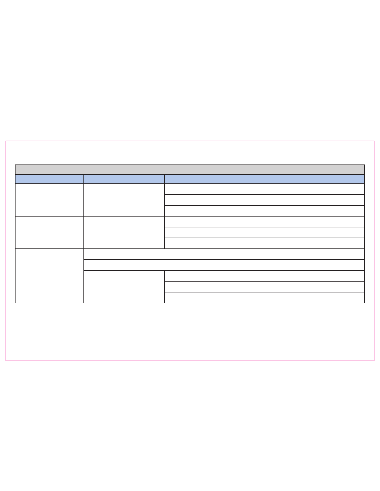
Section 5.2: Supported Biopsy Guns & Needles for Transrectal Procedures
Supported Biopsy Guns & Needles for Transrectal Procedures
Manufacturer Gun Needles
Argon Medical Devices
(US Biopsy®)
Fully Automated Core
Biopsy System, MBD-23
Core Biopsy Needle, 18Gx20cm, CBN1820
Core Biopsy Needle, 18Gx25cm, CBN1825
Core Biopsy Needle, 18Gx30cm, CBN1830
Argon Medical Systems
(Angiotech)
Pro-Mag™ Ultra Automatic
Biopsy Instrument 7675
Pro-Mag™ Biopsy Needle, 18Gx20cm, 765018200
Pro-Mag™ Biopsy Needle, 18Gx25cm, 765018250
Pro-Mag™ Biopsy Needle, 18Gx30cm, 765018300
BARD®
MAX-CORE® Disposable Core Biopsy Instrument, 18Gx20cm, MC 1820
MAX-CORE® Disposable Core Biopsy Instrument, 18Gx25cm, MC 1825
MAGNUM® Reusable Core
Biopsy Instrument, MC 1522
MAGNUM® Disposable Core Tissue Biopsy Needle, 18Gx20cm, MN1820
MAGNUM® Disposable Core Tissue Biopsy Needle, 18Gx25cm, MN1825
MAGNUM® Disposable Core Tissue Biopsy Needle, 18Gx30cm, MN1830
Page 37
To order additional Invivo supplies, consumable instrumentation, or accessories, please contact:
Invivo Customer Service at 1-877-468-4861
Page 30
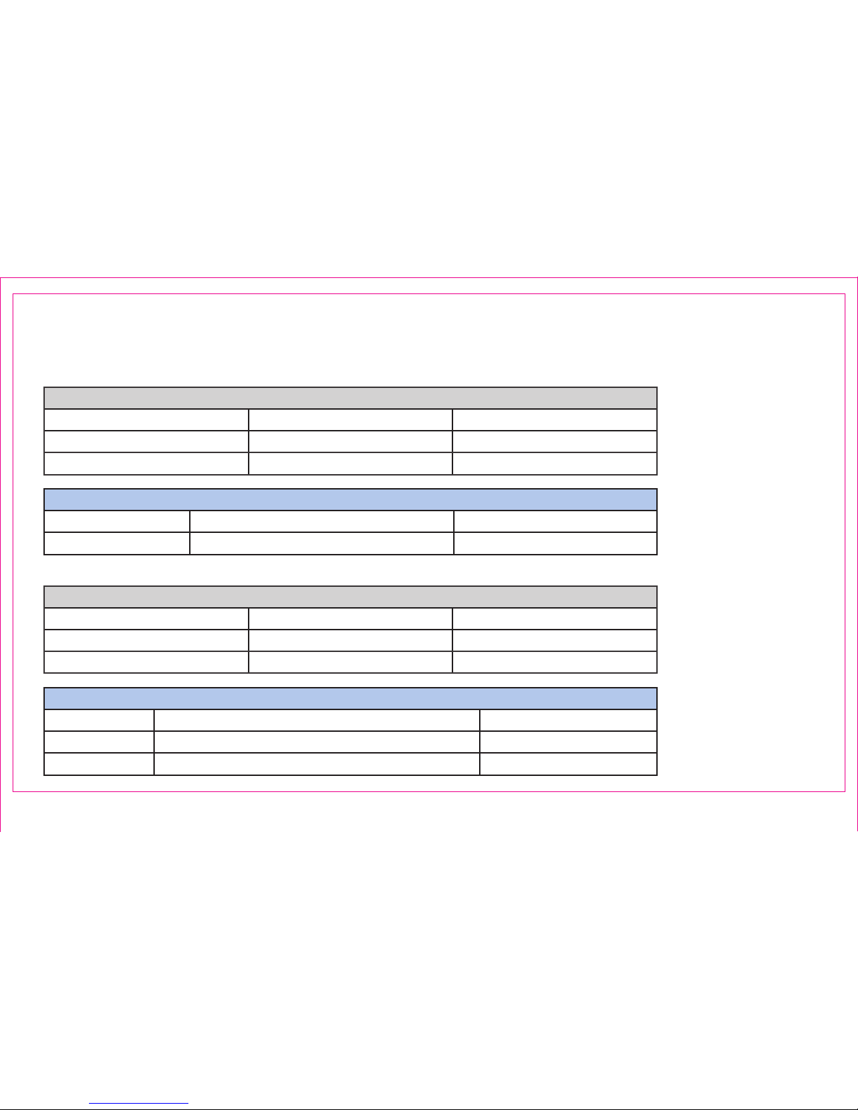
BK 3000/5000 and E10C4
Needle Guides - Available through CIVCO
Manufacturer Description Manufacturer’s part no.
CIVCO Extended, Single-Use Biopsy Guide 610-958
Section 5.2: Supported Biopsy Guns & Needles for Transrectal Procedures
Supported Accessories - Available through Invivo
Description Part Number Reorder Part Number
EM Tracker Assembly 4598-007-83602
FCS0140 (Set of 3)
Probe Holder 4598-007-92361
FCS0136 (Set of 25)
BK 3000/5000 and E14C4T
Needle Guides - Available through BK Medical
Manufacturer Description Manufacturer’s part no.
BK Medical Single-Use Dual Biopsy Guide (All) UA1329-S
BK Medical Single-Use Biplane Biopsy Guide (Sagittal only) UA1322-S
Supported Accessories - Available through Invivo
Description Part Number Reorder Part Number
EM Tracker Assembly 4598-007-83602
FCS0140 (Set of 3)
Probe Holder 4535-303-64631
FCS0135 (Set of 25)
Page 38
Page 31
BK Falcon EXL and 8808
Needle Guides - Available through BK Medical
Manufacturer Description Manufacturer’s part no.
BK Medical Extended, Single-Use Biopsy Guide UA1257S17E
Section 5.2: Supported Biopsy Guns & Needles for Transrectal Procedures (Continued)
Supported Accessories - Available through Invivo
Description Part Number Reorder Part Number
EM Tracker Assembly 4598-007-83602
FCS0140 (Set of 3)
Probe Holder 4535-303-65881
FCS0134 (Set of 25)
BK Flex Focus and 8808e
Needle Guides - Available through BK Medical
Manufacturer Description Manufacturer’s part no.
BK Medical Single-Use Biplane Biopsy Guide UA1322-S
Supported Accessories - Available through Invivo
Description Part Number Reorder Part Number
EM Tracker Assembly 4598-007-83602
FCS0140 (Set of 3)
Probe Holder 4535-303-64631
FCS0135 (Set of 25)
Page 39
Page 32
BK Flex Focus and 8818
Needle Guides - Available through CIVCO
Manufacturer Description Manufacturer’s part no.
CIVCO Extended, Single-Use Biopsy Guide 610-958
Section 5.2: Supported Biopsy Guns & Needles for Transrectal Procedures (Continued)
Supported Accessories - Available through Invivo
Description Part Number Reorder Part Number
EM Tracker Assembly 4598-007-83602
FCS0140 (Set of 3)
Probe Holder 4535-303-64631
FCS0135 (Set of 25)
BK Flex Focus and 8819
Needle Guides - Available through BK Medical
Manufacturer Description Manufacturer’s part no.
BK Medical Single-Use Dual Biopsy Guide (All) UA1329-S
BK Medical Single-Use Biplane Biopsy Guide (Sagittal only) UA1322-S
Supported Accessories - Available through Invivo
Description Part Number Reorder Part Number
EM Tracker Assembly 4598-007-83602
FCS0140 (Set of 3)
Probe Holder 4598-007-92361
FCS0136 (Set of 25)
Page 40
Page 33
BK Hawk and 8808
Needle Guides - Available through BK Medical
Manufacturer Description Manufacturer’s part no.
BK Medical Extended, Single-Use Biopsy Guide UA1257S17E
Section 5.2: Supported Biopsy Guns & Needles for Transrectal Procedures (Continued)
Supported Accessories - Available through Invivo
Description Part Number Reorder Part Number
EM Tracker Assembly 4598-007-83602
FCS0140 (Set of 3)
Probe Holder 4535-303-65881
FCS0134 (Set of 25)
BK Pro Focus and 8818
Supported Accessories - Available through Invivo
Description Part Number Reorder Part Number
EM Tracker Assembly 4598-007-83602
FCS0140 (Set of 3)
Probe Holder 4535-303-64631
FCS0135 (Set of 25)
Needle Guides - Available through BK Medical
Manufacturer Description Manufacturer’s part no.
BK Medical Single-Use Dual Biopsy Guide (All) UA1329-S
BK Medical Single-Use Biplane Biopsy Guide (Sagittal only) UA1322-S
Page 41
Page 34
GE Logiq F8 (software version R2.x.x) and BE9CS
Needle Guides - Available through CIVCO
Manufacturer Description Manufacturer’s part no.
CIVCO Needle Guide 742-338
Section 5.2: Supported Biopsy Guns & Needles for Transrectal Procedures (Continued)
Supported Accessories - Available through Invivo
Description Part Number Reorder Part Number
EM Tracker Assembly 4598-007-83602
FCS0140 (Set of 3)
Probe Holder 4535-303-71191
FCS0055 (Set of 25)
GE Logiq F8 (software version R2.x.x) and E8CS
Needle Guides - Available through CIVCO
Manufacturer Description Manufacturer’s part no.
CIVCO Needle Guide 742-306
CIVCO Needle Guide with latex cover 742-270
Supported Accessories - Available through Invivo
Description Part Number Reorder Part Number
EM Tracker Assembly 4598-007-83602
FCS0140 (Set of 3)
Probe Holder 4535-303-71181
FCS0054 (Set of 25)
Page 42
Supported Accessories - Available through Invivo
Description Part Number Reorder Part Number
EM Tracker Assembly 4598-007-83602
FCS0140 (Set of 3)
Probe Holder 4535-303-71181
FCS0054 (Set of 25)
Supported Accessories - Available through Invivo
Description Part Number Reorder Part Number
EM Tracker Assembly 4598-007-83602
FCS0140 (Set of 3)
Probe Holder 4535-303-71181
FCS0054 (Set of 25)
Page 35
GE Logiq F8 (software versions R1.x.x and R2.x.x) and E8C
Section 5.2: Supported Biopsy Guns & Needles for Transrectal Procedures (Continued)
GE Logiq P5/A5/A5Pro/P6/P6 Pro and E8CS
Needle Guides - Available through CIVCO
Manufacturer Description Manufacturer’s part no.
CIVCO Needle Guide 742-306
CIVCO Needle Guide with latex cover 742-270
Needle Guides - Available through CIVCO
Manufacturer Description Manufacturer’s part no.
CIVCO Needle Guide 742-306
CIVCO Needle Guide with latex cover 742-270
Page 43
Supported Accessories - Available through Invivo
Description Part Number Reorder Part Number
EM Tracker Assembly 4598-007-83602
FCS0140 (Set of 3)
Probe Holder 4535-303-71181
FCS0054 (Set of 25)
Page 36
GE Logiq P5/A5/A5Pro/P6/P6Pro and E8C
Section 5.2: Supported Biopsy Guns & Needles for Transrectal Procedures (Continued)
GE Logiq S7 (software versions R2.x.x) and IC5-9-D
Supported Accessories - Available through Invivo
Description Part Number Reorder Part Number
EM Tracker Assembly 4598-007-83602
FCS0140 (Set of 3)
Probe Holder 4535-303-71181
FCS0054 (Set of 25)
Needle Guides - Available through CIVCO
Manufacturer Description Manufacturer’s part no.
CIVCO Needle Guide 742-306
CIVCO Needle Guide with latex cover 742-270
Needle Guides - Available through CIVCO
Manufacturer Description Manufacturer’s part no.
CIVCO Needle Guide 742-306
CIVCO Needle Guide with latex cover 742-270
Page 44
Supported Accessories - Available through Invivo
Description Part Number Reorder Part Number
EM Tracker Assembly 4598-007-83602
FCS0140 (Set of 3)
Probe Holder 4535-303-71191
FCS0055 (Set of 25)
Supported Accessories - Available through Invivo
Description Part Number Reorder Part Number
EM Tracker Assembly 4598-007-83602
FCS0140 (Set of 3)
Probe Holder 4535-303-71181
FCS0054 (Set of 25)
Needle Guides - Available through CIVCO
Manufacturer Description Manufacturer’s part no.
CIVCO Needle Guide 742-338
Page 37
GE Logiq S7 (software versions R3.x.x) and BE9CS
Section 5.2: Supported Biopsy Guns & Needles for Transrectal Procedures (Continued)
GE Logiq S7 (software versions R3.x.x) and IC5-9-D
Needle Guides - Available through CIVCO
Manufacturer Description Manufacturer’s part no.
CIVCO Needle Guide 742-306
Page 45
Needle Guides - Available through CIVCO
Manufacturer Description Manufacturer’s part no.
CIVCO Needle Guide 644-068
Needle Guides - Available through CIVCO
Manufacturer Description Manufacturer’s part no.
CIVCO Needle Guide 644-068
Hitachi Noblus and C41V
Supported Accessories - Available through Invivo
Description Part Number Reorder Part Number
EM Tracker Assembly 4598-007-83602
FCS0140 (Set of 3)
Probe Holder 4598-013-25761
FCS0146 (Set of 25)
Page 38
Hitachi Arietta Precision and C41V
Section 5.2: Supported Biopsy Guns & Needles for Transrectal Procedures (Continued)
Supported Accessories - Available through Invivo
Description Part Number Reorder Part Number
EM Tracker Assembly 4598-007-83602
FCS0140 (Set of 3)
Probe Holder 4598-013-25761
FCS0146 (Set of 25)
Page 46
*NOTE: Probe Holder
re-orders for the
Philips C10-4ec
must be purchased
directly from CIVCO
(Manufacturer’s part
#667-145)
*NOTE: Probe Holder
re-orders for the
Philips C10-4ec
must be purchased
directly from CIVCO
(Manufacturer’s part
#667-145)
Page 39
Philips Epiq 5/7, Anity and C10-4ec
Needle Guides - Available through CIVCO
Manufacturer Description Manufacturer’s part no.
CIVCO Needle Guide End-re 667-133
CIVCO Tracking Bracket for Endocavity Transducer 667-145
Section 5.2: Supported Biopsy Guns & Needles for Transrectal Procedures (Continued)
Supported Accessories - Available through Invivo
Description Part Number Reorder Part Number
EM Tracker Assembly 4598-007-83602
FCS0140 (Set of 3)
Needle Guides - Available through CIVCO
Manufacturer Description Manufacturer’s part no.
CIVCO Tracking Bracket for Endocavity Transducer 667-145
CIVCO Needle Guide 667-133
Philips Aniti 50/70 and C10-4ec
Supported Accessories - Available through Invivo
Description Part Number Reorder Part Number
EM Tracker Assembly 4598-007-83602
FCS0140 (Set of 3)
Page 47
Page 40
Philips iU22 and C9-5ec
Section 5.2: Supported Biopsy Guns & Needles for Transrectal Procedures (Continued)
Supported Accessories - Available through Invivo
Description Part Number Reorder Part Number
EM Tracker Assembly 4598-007-83602
FCS0140 (Set of 3)
Probe Holder 4598-010-06681
FCS0105 (Set of 25)
Needle Guides - Available through CIVCO
Manufacturer Description Manufacturer’s part no.
CIVCO Needle Guide 613-246
CIVCO Needle Guide with Cover 613-245
Philips HD11XE and C9-5ec
Supported Accessories - Available through Invivo
Description Part Number Reorder Part Number
EM Tracker Assembly 4598-007-83602
FCS0140 (Set of 3)
Probe Holder 4598-010-06681
FCS0105 (Set of 25)
Needle Guides - Available through CIVCO
Manufacturer Description Manufacturer’s part no.
CIVCO Needle Guide 613-246
CIVCO Needle Guide with Cover 613-245
Page 48
Needle Guides - Available through CIVCO
Manufacturer Description Manufacturer’s part no.
CIVCO Needle Guide End-re 676-132
Supported Accessories - Available through Invivo
Description Part Number Reorder Part Number
EM Tracker Assembly 4598-007-83602
FCS0140 (Set of 3)
Probe Holder 4598-007-92371
FCS0164 (Set of 25)
Page 41
Siemens Acuson X150/X300 and EC9-4
Section 5.2: Supported Biopsy Guns & Needles for Transrectal Procedures (Continued)
Needle Guides - Available through CIVCO
Manufacturer Description Manufacturer’s part no.
CIVCO Needle Guide 676-157
Siemens Acuson S2000 / S3000 and MC9-4
Supported Accessories - Available through Invivo
Description Part Number Reorder Part Number
EM Tracker Assembly 4598-007-83602
FCS0140 (Set of 3)
Probe Holder 4598-007-92382
FCS0165 (Set of 25)
Page 49
Needle Guides - Available through CIVCO
Manufacturer Description Manufacturer’s part no.
CIVCO Needle Guide 674-015
Page 42
Section 5.2: Supported Biopsy Guns & Needles for Transrectal Procedures (Continued)
Sonosite MicroMaxx® and C8x
Supported Accessories - Available through Invivo
Description Part Number Reorder Part Number
EM Tracker Assembly 4598-007-83602
FCS0140 (Set of 3)
Probe Holder 4535-303-65891
FCS0078 (Set of 25)
Page 50
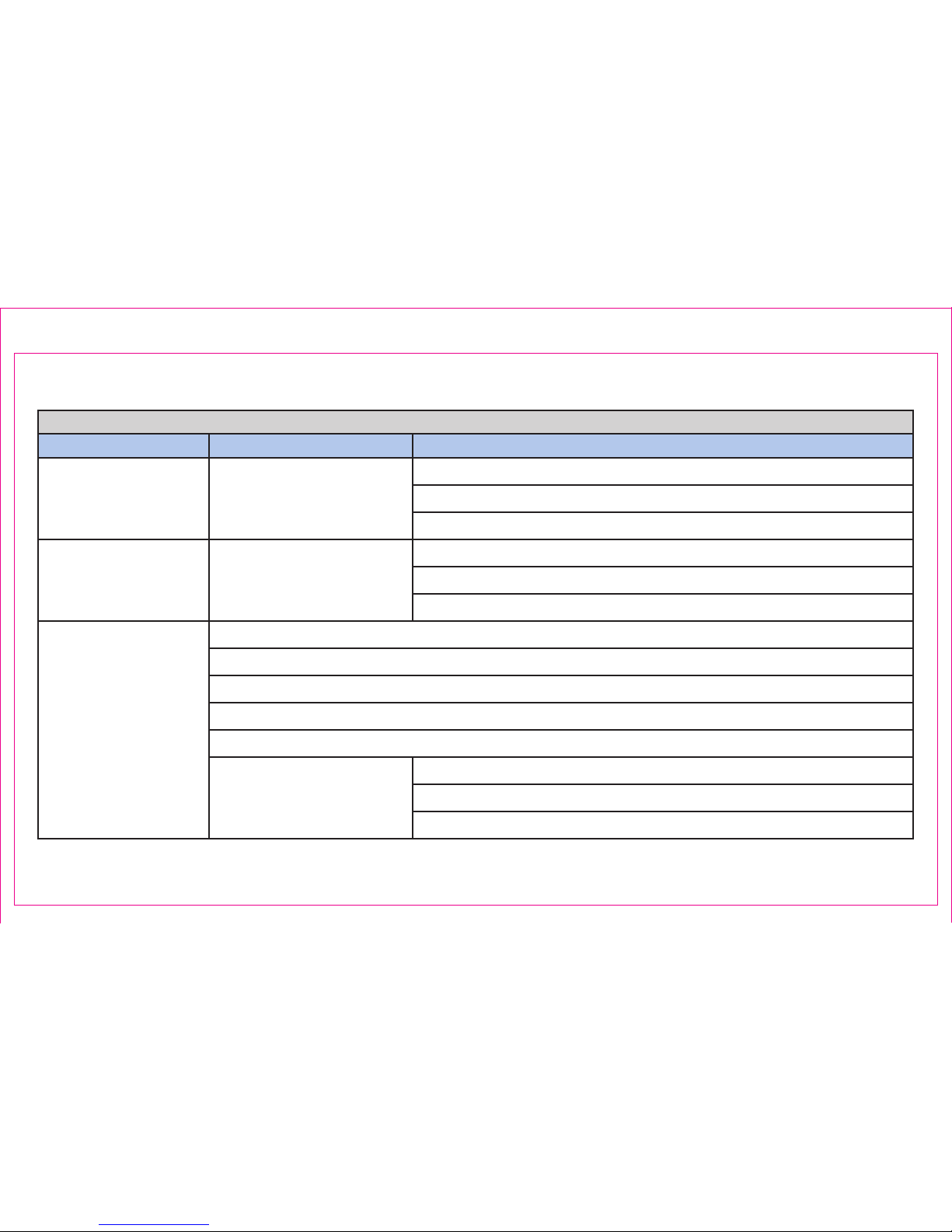
Supported Biopsy Guns & Needles for Transperineal Procedures
Manufacturer Gun Needles
Argon Medical Devices
(US Biopsy®)
Fully Automated Core
Biopsy System, MBD-23
Core Biopsy Needle, 18Gx20cm, CBN1820
Core Biopsy Needle, 18Gx25cm, CBN1825
Core Biopsy Needle, 18Gx30cm, CBN1830
Argon Medical Systems
(Angiotech)
Pro-Mag™ Ultra Automatic
Biopsy Instrument 7675
Pro-Mag™ Biopsy Needle, 18Gx20cm, 765018200
Pro-Mag™ Biopsy Needle, 18Gx25cm, 765018250
Pro-Mag™ Biopsy Needle, 18Gx30cm, 765018300
BARD®
MAX-CORE® Disposable Core Biopsy Instrument, 18Gx20cm, MC 1820
MAX-CORE® Disposable Core Biopsy Instrument, 18Gx25cm, MC 1825
Mission™ Disposable Core Biopsy Instrument Kit, 18Gx20cm, MC 1820MSK
Mission™ Disposable Core Biopsy Instrument, 18Gx20cm, MC 1820MS
TruGuide® Disposable Coaxial Biopsy Needle, 17Gx17.8cm, C1820A
MAGNUM® Reusable Core
Biopsy Instrument, MC 1522
MAGNUM® Disposable Core Tissue Biopsy Needle, 18Gx20cm, MN1820
MAGNUM® Disposable Core Tissue Biopsy Needle, 18Gx25cm, MN1825
MAGNUM® Disposable Core Tissue Biopsy Needle, 18Gx30cm, MN1830
Page 43
Section 5.3: Supported Biopsy Guns & Needles for Transperineal Procedures
Page 51
Page 44
*Note: Perineologic parts can be ordered directly from the manufacturer by phone (240-727-7662) or email ([email protected]).
Section 5.3: Supported Biopsy Guns & Needles for Transperineal Procedures (Continued)
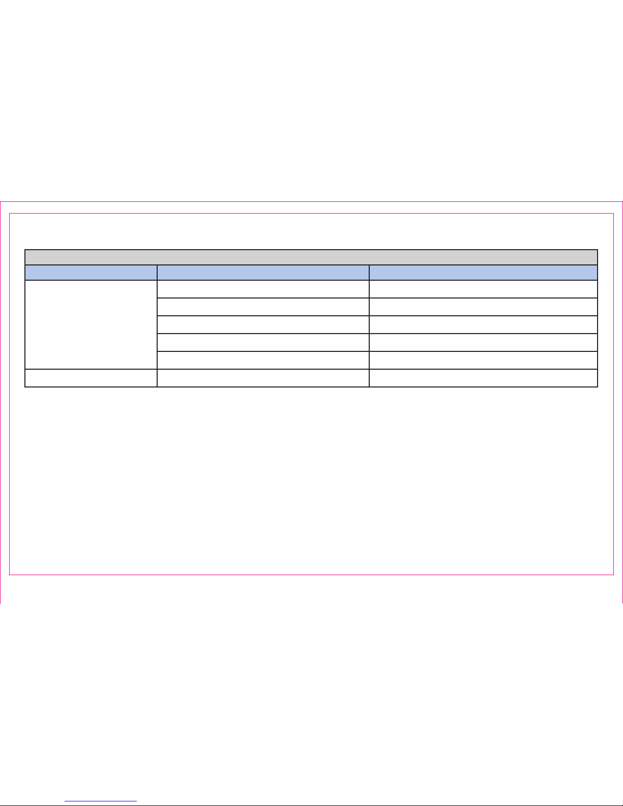
Supported Accessories for Transperineal Procedures
Manufacturer Description Manufacturer’s Part Number
CIVCO
Sterile 17G Grid 610-905
Sterile 18G Grid 610-906
Sterile 14G Grid 610-977
Sterile Flat Polyethylene Drape UA2007
Latex-Free Endocavity Balloon 610-898
Perineologic* PrecisionPoint™ Transperineal Access System P1001, P1002
Page 52
Page 45
Section 5.3: Supported Biopsy Guns & Needles for Transperineal Procedures (Continued)
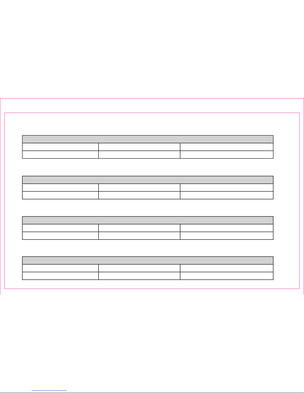
BK 3000/5000 and E14CL4b
Supported Accessories - Available through Invivo
Description Part Number Reorder Part Number
EM Tracker Assembly 4598-007-83602
FCS0140 (Set of 3)
Supported Accessories - Available through Invivo
Description Part Number Reorder Part Number
EM Tracker Assembly 4598-007-83602 FCS0140 (Set of 3)
BK Flex Focus and 8848
BK Pro Focus and 8848
Supported Accessories - Available through Invivo
Description Part Number Reorder Part Number
EM Tracker Assembly 4598-007-83602 FCS0140 (Set of 3)
Hitachi Noblus and C41L47RP
Supported Accessories - Available through Invivo
Description Part Number Reorder Part Number
EM Tracker Assembly 4598-007-83602 FCS0140 (Set of 3)
Page 53

Section 6: Transperineal Workow
6.1 Tool Setup / Field Generator Positioning
6.2 Transperineal Biopsy Procedure
Note: Refer to “Pre-Biopsy Steps” in Section 2: UroNav Intra-Procedure of this document for:
• Review Segmentation & Targets Screen
• TRUS Side-Fire Sweep & Edit 3D Segmentation
• Registration – Align US Volume with MR
Note: Refer to the Instructions for Use Appendix E for Transperineal Hardware Setup
UroNav Transperineal
Workow
Page 54
Page 46
Section 6: Transperineal Workow
Section 6.1: Tool Setup / Field Generator (FG) Positioning
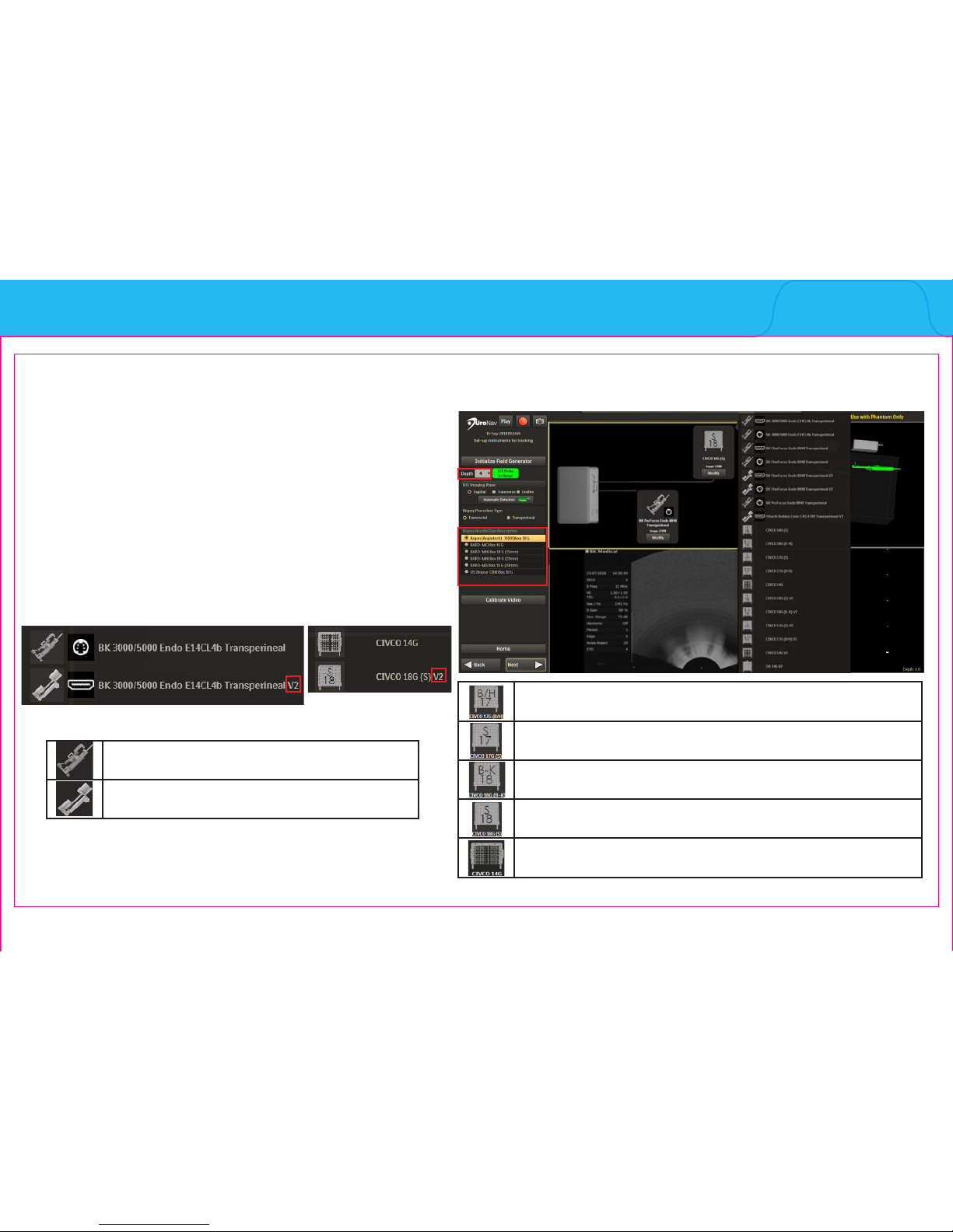
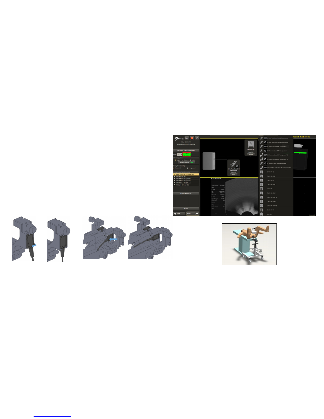
Initialize Navigation and Biopsy Instrument Tools
1. Match Depth on UroNav to Depth Display on US
2. Conrm Biopsy Needle/Gun
3. Verify FG Tracker Connection, US Model and
Probe Selection
Note: Transperineal V2 indicates second generation
stepper
Select for 17 gauge grid with B/H side facing user
Select for 17 gauge grid with S-side facing user
Select for 18 gauge grid with B-K side facing user
Select for 18 gauge grid with S-side facing user
Select for 14 gauge grid
Note: See Section 5: UroNav Supported Supplies
of this document for list of US models, probes and
biopsy supplies compatible with UroNav.
1
3
2
Indicates rst generation stepper
Indicates second generation stepper
Note:
Page 55
Page 47
Section 6.1: Tool Setup / Field Generator (FG) Positioning (Continued)
Initialize Navigation Tools to create Electromagnetic
(EM) Field for Fusion Registration, Targeting, and
Recording Biopsy Core Samples
4. EM Tracker Status
• The color represents the range found within
the generated EM eld
• Green color shows tracking “In Range”
4
4
Note: See Section 5: UroNav Supported Supplies
of this document for list of US models, probes and
biopsy supplies compatible with UroNav.
Position FG directly
over tracking device(s)
following US probe
insertion
Apply force until both EM trackers are ush.
(Second generation stepper shown)
Page 56
Page 48
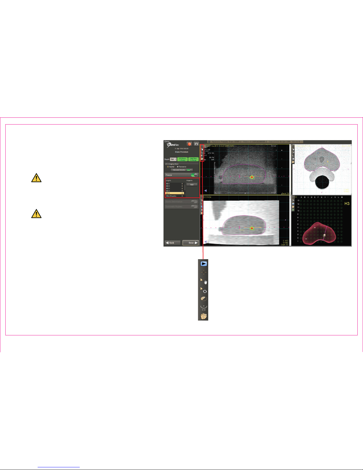
1. Image Action Commands within any 2D
viewport realign the anatomical landmarks of
the magenta MR boundary to be in line with
the US image
Maintaining alignment is necessary
throughout the procedure and may
require multiple adjustments using the
Stepper and Stepper Arm devices
Failure to successfully align the US
with the MRI requires returning to the
Sweep and Segmentation screen
2. Select Target(s) and Biopsies List
Right Click for a Context Menu to:
• Delete / Rename biopsy
• View PI-RADS (if available)
• Add to record a screenshot of biopsy
location
Section 6.2: Transperineal Biopsy Procedure
2
1
Page 57
4
3
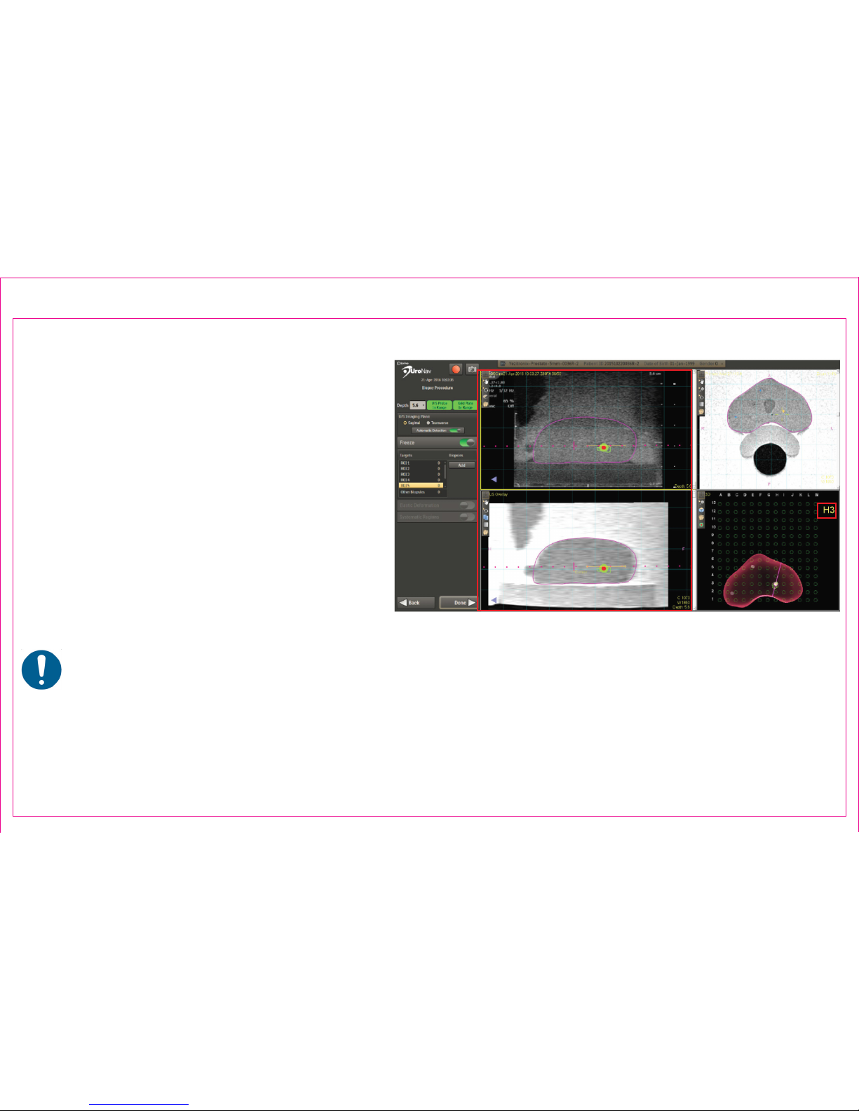
Navigation Guidance to Pre-Dened Targets
3. Rotate the transducer in the stepper
assembly. Use the projected U/S plane
intersection to view the target
• The rectangular grid array provides
navigation guidance on where the
needle is to be inserted
4. Ensure the biopsy guideline intersects the
target
• Advance the needle through the
highlighted grid hole (3)
• Monitor needle trajectory
The clinician has the exibility to use the
highlighted grid hole or manually override the
selection to insert the needle
Page 49
Section 6.2: Transperineal Biopsy Procedure (Continued)
Page 58
10
8
6
5
7
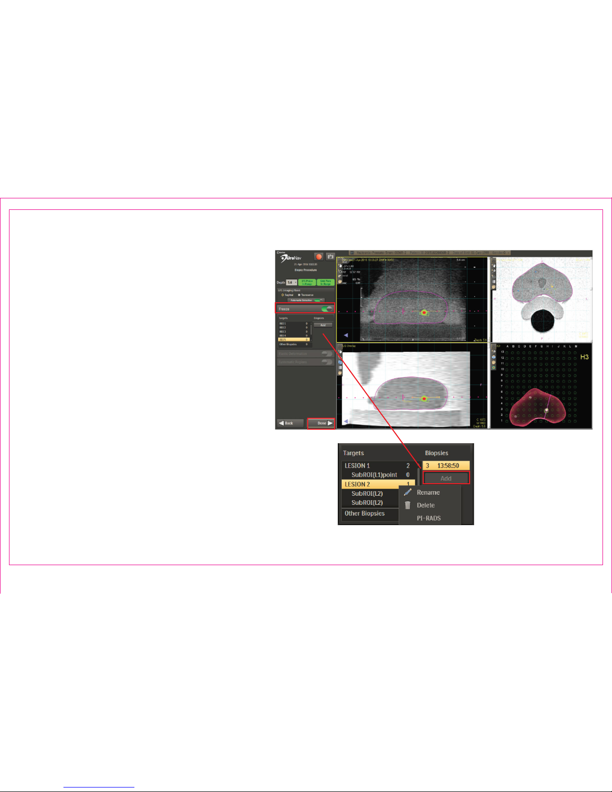
Acquiring a Biopsy Sample
5. When the biopsy sample is taken, select
Freeze or depress/release the foot pedal to
interrupt real-time, cine viewing
6. Scroll through the US frames to where
the distal tip of the biopsy needle is fully
deployed
7. Double Click to mark the distal tip
8. Press Add to automatically record a screen
capture the location and associate it with
the current target and resume real-time, cine
viewing
9. Repeat alignment registration for additional
samples or select next lesion and proceed to
navigate
10. Press Done when complete
Page 50
Section 6.2: Transperineal Biopsy Procedure (Continued)
Page 59

This Quick Reference Guide is intended for use only with UroNav software version 3.0
To determine version number, press F1 after logging into UroNav.
© 2018 Invivo Corporation All Rights Reserved
4598-015-71681 Rev 1
Page 51
Page 60

© 2018 Invivo Corporation All Rights Reserved
4598-015-71681 Rev 1
 Loading...