

Invivo MagnitudeTM 3150M MRI, Omni-TrakTM 3150 MRI User manual


Invivo Research, Inc
MagnitudeTM 3150M MRI Monitor
Omni-TrakTM 3150 MRI Monitor
Operations Manual
INVIVO
RESEARCH
INCORPORATED
12601 Research Parkway
Orlando, FL 32826
1-800-331-3220
1-407-275-3220
www.invivoresearch.com


TABLE OF CONTENTS
Paragraph Number Page Number
List of Figures ............................................................... iii
Equipment Classification ....................................................... iii
Precautions .................................................................. iv
User Responsibility ........................................................... xi
MRI Accessories ............................................................ xii
1. INTRODUCTION .................................................... 1-1
1.1 Features ............................................................. 1-1
1.2 Use of this Manual ..................................................... 1-2
1.3 Product Description .................................................... 1-2
1.3.1 System Parameters ............................................... 1-2
1.3.2 User Interface ................................................... 1-2
1.3.3 Versatility ...................................................... 1-2
1.4 Top Panel ............................................................ 1-2
1.4.1 Control Panel ................................................... 1-3
1.4.2 Flat Panel Display ............................................... 1-4
1.5 System Screen ........................................................ 1-6
1.6 Parameter Input Panel .................................................. 1-6
1.7 Monitoring System Location ............................................. 1-6
1.7.1 MRI Monitoring Components ...................................... 1-7
1.7.2 3150(M) MRI Monitoring Precautions ............................... 1-7
1.8 Cleaning Instructions ................................................... 1-8
1.8.1 Cleaning Accessories .............................................. 1-9
2. INSTALLATION ..................................................... 2-1
2.1 Introduction .......................................................... 2-1
2.2 Monitor Installation .................................................... 2-1
2.2.1 Monitor Location ................................................ 2-1
2.2.2 Preparing the 3150(M) MRI Monitor for Use .......................... 2-1
2.2.3 Monitor Start Up ................................................ 2-2
2.2.4 3150(M) MRI Monitor/Remote Monitor Communication ................ 2-2
3. MONITOR PREPARATION FOR USE .................................. 3-1
3.1 Introduction .......................................................... 3-1
3.2 ECG Setup ........................................................... 3-1
3.3 Pressure Zeroing ...................................................... 3-1
3.4 NIBP Setup .......................................................... 3-1
3.5 Alarm System ......................................................... 3-1
4. PATIENT PARAMETERS ............................................. 4-1
4.0 Introduction .......................................................... 4-1
4.1 ECG Monitoring ...................................................... 4-1
4.1.1 Monitoring Precautions ........................................... 4-1
4.1.2 Maintenance of Optimum ECG Waveform Integrity ..................... 4-3
4.1.3 Associated Displays .............................................. 4-4
i

TABLE OF CONTENTS
Paragraph Number Page Number
4.1.4 ECG Con trol Keys ............................................... 4-4
4.1.5 Alarm Limits ................................................... 4-4
4.2 NIBP Monitoring ...................................................... 4-4
4.2.1 Simplified Theory of Operation ..................................... 4-4
4.2.2 Patient and Cuff Preparation ....................................... 4-5
4.2.3 Associated Displays .............................................. 4-6
4.2.4 Adult/Neonate Selection .......................................... 4-6
4.2.5 NIBP Control Keys .............................................. 4-6
4.2.6 Alarm Limits ................................................... 4-6
4.2.7 Blood Pressure Reading Intervals ................................... 4-7
4.2.8 NIBP Normal Operation .......................................... 4-7
4.3 Invasive Pressure Monitoring ............................................ 4-7
4.3.1 Probe Preparation ................................................ 4-7
4.3.2 Zeroing Pressure Channels ......................................... 4-8
4.3.3 Associated Displays .............................................. 4-8
4.3.4 Alarm Limits ................................................... 4-8
4.4 SpO2 Monitoring ...................................................... 4-9
4.4.1 SpO2 Monitoring Considerations ................................... 4-9
4.4.2 Patient and Probe Preparation ...................................... 4-9
4.4.3 Associated Displays .............................................. 4-9
4.4.4 Alarms ....................................................... 4-10
4.4.5 SpO2 Messages ................................................ 4-10
4.5 End Tidal CO2 Monitoring (EtCO2) ...................................... 4-10
4.5.1 Theory of Capnography .......................................... 4-11
4.5.2 Patient Circuit Preparation ........................................ 4-11
4.5.3 Associated Displays ............................................. 4-12
4.5.4 EtCO2 Alarms ................................................. 4-13
4.5.5 EtCO2 Messages ............................................... 4-13
4.6 Cardiac/Peripheral Gating Option ........................................ 4-13
5.0 BATTERY OPERATION .............................................. 5-1
5.1 Introduction .......................................................... 5-1
5.2 Battery Location and Access ............................................. 5-1
5.3 Battery Charging ...................................................... 5-1
5.4 Battery Operation Time ................................................. 5-1
5.4.1 Battery Low Indication ............................................ 5-1
5.4.2 Maintaining Battery Life .......................................... 5-1
5.5 Battery Replacement ................................................... 5-1
Appendix A: Specifications ................................................... A-1
Appendix B: Repair ..........................................................B-1
Appendix C: Warranty ........................................................C-1
Appendix D: Declaration of Conformity ......................................... D-1
Appendix E: Primer for Patient ECG Monitoring During MRI Procedures ...............E-1
Appendix F: List of Symbols ...................................................F-1
ii

LIST OF FIGURES
Figure Number Page Number
1-1 3150(M) MRI Monitor Top Panel ......................................... 1-2
1-2 Control Panel ......................................................... 1-3
1-3 The Normal Screen .................................................... 1-4
1-4 The Informational Display ............................................... 1-4
1-5 Vital Signs Trace Display ................................................ 1-5
1-6 Vital Signs Numeric Display ............................................. 1-5
1-7 Parameter Input Panel .................................................. 1-6
2-1 The Power Adapter and RF Antenna Connectors ............................. 2-2
4-1 Patient Placed in Magnet Bore Head First ................................... 4-2
4-2 Electrode Placement .................................................... 4-2
4-3 Patient Placed in Magnet Bore Feet First .................................... 4-3
4-4 The ECG Display ...................................................... 4-4
4-5 Oscillometric Measurement Method ....................................... 4-5
4-6 The NIBP Display ..................................................... 4-6
4-7 The Invasive Pressure Display ............................................ 4-8
4-8 The SpO2 Display ..................................................... 4-9
4-9 The EtCO2 Display ................................................... 4-12
EQUIPMENT CLASSIFICATION
Classification according to IEC-601-1
According to the type of protection against
electrical shock:
According to the degree of protection against
electrical shock:
According to the degree of protection against
harmful ingress of water.
According to the methods of sterilization or
disinfection:
According to the mode of operation: Continuous operation.
Equipment not suitable for use in the presence of a flammable anesthetic mixture with air or
with oxygen or nitrous oxide.
Class I equipment.
Type CF (defibrillator-proof) equipment.
Ordinary equipment (enclosed equipment
without protection against ingress of water).
Non-sterilizable. Use of Liquid surface
disinfectants only.
iii

PRECAUTIONS
NOTE
This Operations Manual will describe both the MagnitudeTM 3150M and Omni-TrakTM 3150 MRI
Monitors in detail. For simplicity the manual will refer to both these systems by the name “3150(M) MRI
Monitor” except in the cases where a feature applies only to one of the two systems, in which case the
specific 3150(M) MRI system will be referenced.
General
Federal law in the USA or Canada restricts this device to sale by, or on , the order of a physician.
The 3150(M) MRI Patient Monitoring System is comprised of the 3150(M) MRI Monitor and a
Remote Monitor (Millennia® 3155MVS or 3155A). Always operate the 3150(M) MRI Monitor with
its designated remote monitor.
The accuracy of the measurements can be affected by the position of the patient, the patient’s
physiological condition, and other factors. Always consult a physician for interpretation of
measurements made by this monitor.
To avoid remote monitor fall, secure monitor on the shelf or bracket prior to use.
An explosion hazard exists if this monitor is used in the presence of flammable anesthetics.
The operator should read and thoroughly understand this manual and the associated remote monitor
manual (Invivo Research, Inc. Part Number 9545) completely before attempting to operate the 3150(M)
MRI Monitor.
If any system failure occurs (e.g. an unexplained continuous audible alarm) remove the monitor from
use, and refer it to qualified service personnel.
When the message “SOUND OFF”is displayed on the 3150(M) MRI Monitor (an “X” is displayed on
the screen of the remote 3155 MVS or 3155A monitor), the audible alarm tone will not sound for any
reason.
Perform operational checkout before each use. If monitor fails to function properly, refer to qualified
service personnel.
For safe and accurate operation and MRI compatibility, use only recommended Invivo Research patient
electrodes, cabling, lead wires, cuffs, hoses, sensors, tubing, etc. A listing of these can be found in the
Accessory Listing within this manual, or by contacting Invivo Research directly.
For continued operation, always connect the monitor to AC Main Power through the AS153 AC Power
Adapter when a Low Battery indication occurs. Failure to do this can lead to interruption of monitoring
and/or damage to the monitor’s battery(s).
The system may not conform to all performance specifications if stored or used outside the
environmental specifications identified in Appendix A in the rear of this manual.
Do not apply any unnecessary pressure to the screen area of the monitor. Severe pressure applied to this
portion of the monitor could result in damage or failure of this screen.
All equipment not complying with IEC 601-1 should be placed outside the patient environment. Only
connect IEC 601-1 compliant equipment to this monitor. To avoid potentially hazardous leakage
currents, always check the summation of leakage currents when several items of equipment are
interconnected.
For proper equipment maintenance, perform the service procedures at the recommended intervals as
described in the monitor’s service manual.
Single use devices should never be reused.
iv

PRECAUTIONS (Continued)
Electrical Safety
To avoid an electrical hazard, never immerse the unit in any fluid or attempt to clean it with liquid
cleaning agents. Always disconnect monitor from AC Main Power before performing cleaning or
maintenance.
Shock hazard exists if operated without chassis cover. Refer servicing to qualified service personnel
only.
For continued protection against fire hazard, replace fuses with same type and rating only.
Avoid use of electrical power extension cords. Electrical power extension cords may create a safety
hazard by compromising the grounding integrity of the monitor.
If the integrity of the earth conductor of the AC main power cable is in doubt, operate the monitor
on internal battery power until proper earth connection is confirmed.
If monitor becomes accidentally wet during use, discontinue operation of the monitor until all
affected components have been cleaned and permitted to dry completely. Contact your local Invivo
Research, Inc. representative if additional information is required.
This monitor and its listed accessories may be safely powered by the voltages 110-120/220-240 VAC
having a frequency of 50 or 60 Hz.
MRI Use Precautions
Certain components of this device will be affected by the magnetic and radio frequency fields present
in your MRI System. Confer with your MRI physicist and/or Radiology staff to identify the proper
placement and use areas for the monitor and its accessories, as defined on the monitor or accessory
labeling. Failure to properly place the monitor and its accessories in the Magnet Room will result
in monitor failure, and possible patient or user injury. Always position the 3150(M) MRI Monitor
at, or outside, the 5000 Gauss (0.5T) field line of the MRI system. A slight distortion of the MRI
magnetic field homogeneity could result or possible damage to either the monitor's NIBP or EtCO2
pump could occur.
Always verify proper communication of the 3150(M) MRI Monitor with the Remote Monitor(s)
prior to patient use.
MRI Magnet Room Placement. The 3150(M) MRI Monitor is designed to be used in conjunction
with one or two remote monitor(s). The 3150(M) MRI Monitor is specially designed not to
interfere with MRI operations and may be used inside the MRI Magnet Room in any location at or
outside the 5000 Gauss (0.5T) Field Line of the MRI System. If brought closer than the 5000 Gauss
Field Line, the NIBP monitor pump and EtCO2 pump may fail to operate.
The Remote Monitor(s) are also specifically designed not to interfere with MRI operations, and may
be used in the Magnet Room at or outside the 1000 Gauss (0.1T) Field Line of the MRI System. If
brought closer than the 1000 Gauss Field Line, monitor damage (failure to operate) may result.
Risk of RF current burn. Cables which become inadvertently looped during MRI act as conductive
lines for RF induced currents. When lead wires or other cables form a conductive loop in contact
with the patient's tissue, minor to severe burning can result.
v

PRECAUTIONS (Continued)
MRI Use Precautions (Continued)
Perform the following to minimize risk of RF current burn:
1. Place cables and lead wires neatly in straight alignment with no looping.
2. Keep the length of lead wires and patient cable within the bore to a minimum.
3. RF burn risk increases when multiple sensors/cables are in use. Such combinations are not
recommended.
4. The high radio frequency (RF) power used in MRI scanning poses an ever-present risk of
excessive heat at the monitoring sites and, therefore, the risk of RF current burn. Should
power levels greater than S.A.R. of 4 w/kg peak (0.4 w/kg average) be used, the risk of
patient burn greatly increases. As a result, monitoring of ECG or Respiration (derived
from ECG leads) at power levels of greater than 4 w/kg peak (0.4 w/kg average) is not
recommended for the general patient population. Such monitoring should only be attempted
on conscious patients with good temperature reflex so they may warn the operator of
excessive heat at the monitoring sites.
5. High RF Power may cause patient heating or burns. For scans with average S.A.R. > 1 w/kg,
limit scan time to 5 minutes and pause at least 3 minutes between scans to allow ECG Cable
to cool.
MRI Compatibility
The Quadtrode® MRI ECG Electrode Pad, and ECG Patient Lead Wires and Cable, are
compatible with Magnetic Resonance Imaging (MRI) Systems within the following
guidelines:
! MRI systems with static magnetic field strengths up to 1.5 Tesla.
! Usable within the MRI system bore with Specific Absorption Ratios (S.A.R.'s) up
to 4.0 w/kg (peak). Use with higher S.A.R.'s greatly increases the risk of patient
burns.
! Non-Magnetic materials are used in the construction of these assemblies.
! If scanned directly across the plane of the ECG electrode element, a slight image
distortion may be seen at the skin surface where the electrode element is
positioned.
ECG
For best ECG and Heart Rate monitoring, always select the optimum lead configuration which has
the least artifact and largest waveform(s) being detected for monitoring use.
Failure to respond to a Lead Fail alarm will cause a lapse in your patient’s monitoring. Always
respond promptly to this and any other alarms.
MRI induced radiofrequency artifact can sometimes cause inaccurate heart rates. Inspect the ECG
waveform during MRI scanning if spurious heart rates are observed.
vi

PRECAUTIONS (Continued)
ECG (Continued)
Bo (static) magnetic field artifact can present artificially-induced augmented T waves during ECG
monitoring. Due to the effects of the magnetic field on the moving blood of the patient, follow the
recommended ECG Electrode Placement to minimize this type of artifact.
An inoperative ECG monitor is indicated by absence of an ECG waveform and a simultaneous Lead
Fail alarm.
Heart rate values may be adversely affected by cardiac arrhythmia, or by operation of electrical
stimulators.
Pressures
For best invasive pressure monitoring, always select the appropriate waveform scale for the
waveform being observed.
For invasive pressure monitoring, routinely inspect the catheter and/or pressure line for leaks after
zeroing. Always follow the pressure transducer/catheter manufacturer’s use recommendations.
Never place the pressure transducer(s) within the MRI bore. Transducer failure or noisy MRI images
can result.
Invasive blood pressure transducers are sensitive to vibrations that can occur during MRI scanning,
which can lead to pressure reading inaccuracies. Always mount the invasive blood pressure
transducer away from areas where vibration is likely to occur.
Always zero the pressure transducer(s) prior to patient use.
Non-physiological pulsatile invasive pressure waveforms (e.g., such as found during intra-aortic
balloon pump use) can lead to inaccurate blood pressure readings. If questionable values are
observed, re-check patient’s pressures by alternate means before administering medication or
therapy.
Air that may be trapped within the pressure transducer or its associated tubing should be removed
by flushing the system following established hospital or catheter lab procedures.
The fluid within the pressure transducer system is a conductive connection to the patient, and should
not contact other conductive parts, including earth ground.
NIBP
Use only MRI Compatible NIBP Accessories (See MRI Accessory list in this Section).
When using the NIBP portion of this instrument to measure blood pressure, remember that the
patient’s blood pressure readings are not continuous, but are updated each time a blood pressure
measurement is taken. Set a shorter interval for more frequent updating of the patient’s blood
pressure.
Do not attach the cuff to a limb being used for infusion. Cuff inflation can block infusion, possibly
causing harm to the patient.
Frequent NIBP measurements can cause pooling of the blood in the limb (hemostasis), and
peripheral tissue/nerve damage. Allow sufficient time for blood recirculation to prevent pooling of
the blood in the limb.
Arrhythmic and/or erratic heart beats (or severe motion artifact, such as tremors or convulsions) can
result in inaccurate readings and/or prolonged measurements. If questionable readings are obtained,
re-check patient’s vital signs by alternate means before administering medication.
vii

PRECAUTIONS (Continued)
NIBP (Continued)
To prevent possible nerve damage to the limb, apply the NIBP cuff as recommended by current AHA
guidelines for blood pressure monitoring.
To ensure accurate and reliable measurements, use only recommended patient cuffs/hoses. For best
accuracy, use the appropriate cuff size for each patient as recommended by the current AHA
guidelines for blood pressure monitoring.
Always tighten the cuff air hose connections snugly into place for proper operation.
Some reusable NIBP cuffs contain a medical-grade latex rubber. Patients sensitized to latex rubber
can have an allergic reaction when exposed to this material. Avoid the use of cuffs which contain
latex rubber on patients who are allergic to this material.
Routinely inspect the cuff and hose assemblies for proper attachment and orientation. Replace cuff
and/or hose assemblies with cracks, holes, tears, cuts, etc. that could cause leaks in the system. If
cuff and/or hose assemblies with damage which could result in leaks are used, prolonged and/or
inaccurate patient readings could result.
To prevent skin abrasion, apply and remove cuff carefully. Keep Velcro® (hook and latch) retention
areas away from the skin.
Always use recommended NIBP cuffs and hoses. Avoid compression or restriction of NIBP cuff
hose.
SpO2
Use only MRI compatible fiberoptic SpO2 accessories (See MRI Accessory list in this Section).
Use only the Fiberoptic SpO2 sensors recommended by Invivo Research, Inc. A listing of these can
be found in the Accessory List within this manual, or by contacting Invivo Research, Inc. directly.
The Fiberoptic SpO2 sensors are constructed of fiberoptic glass and should always be handled with
care to prevent damage. Improper handling can reduce both the signal transmission quality and the
SpO2 measurement sensitivity. Improper handling can also shorten the SpO2 sensor's useful life.
The numeric measurement values are updated every 1 second on the monitor display.
The pulse oximeter feature in this monitor is designed to display functional SpO2 values.
The pulse oximeter pulsatile waveform is not proportional to the pulse amplitude, but adjusts the
waveform amplitude as needed for proper viewing.
All monitor alarms are categorized as medium priority, unless otherwise specified.
Avoid placement of the SpO2 probe on the same limb with an inflated blood pressure cuff. Cuff
inflation could result in inaccurate readings and false alarm violations.
SpO2 monitoring requires the detection of valid pulses to correctly determine SpO2 and Heart Rate
values. During conditions of gross artifact, or in the absence of valid pulses, the SpO2 /rate values
may not be correct.
viii

PRECAUTIONS (Continued)
SpO2 (Continued)
The SpO2 monitoring portion of this monitor is intended to measure arterial hemoglobin oxygen
saturation of functional hemoglobin (saturation of hemoglobin functionally available for transporting
oxygen in the arteries). Significant levels of dysfunctional hemoglobins, such as carboxyhemoglobin
or meth emoglobin, may affect the accuracy of the measurement. Also, Cardiogreen and other
intravascular dyes may, depending on their concentration, affect the accuracy of the SpO2
measurement.
Always shield the SpO2 sensor from extraneous incident light sources. Such extraneous light can
cause SpO2 reading or pulse detection errors.
Frequently inspect the SpO2 sensor site for possible pressure tissue necrosis during prolonged
monitoring. Reposition the sensor at least every 4 hours. Special care should be exercised when
tape is used to secure the sensor, as the stretch memory properties of most tapes can easily apply
unintended pressure to the sensor site.
EtCO2
Always select the appropriate EtCO2 Tubing Set and gas sampling flow rate for the patient being
monitored. Verify that the patient’s breathing efforts and timing coincide with the monitor’s
waveform before completion of the patient set-up.
Frequently inspect the EtCO2 patient tubing for proper gas flow. Avoid kinking of the EtCO2
patient tubing that can result in leaking, reduction, or cut-off of the sample gas flow. Inaccurate gas
measurements could result.
During EtCO2 monitoring, always use the appropriate water vapor evacuating tubing (i.e. Nafion
tubing) included in the patient circuit tubing kit to prevent inaccurate EtCO2 readings due to water
vapor content of the patient's exhaled breath.
For proper operation, check the EtCO2 calibration during routine service. Routine calibration should
not be required, but if the specified operation does not occur, have a qualified service person recheck
the calibration. Proper re-calibration can only be performed during factory service.
EtCO2 patient tubing and its associated components are intended for single-patient use only. Avoid
cleaning or disinfecting these items for reuse. Inaccurate gas measurements could result.
To prevent inaccurate or missed readings, keep the EtCO2 patient tubing clear of any moving
mechanisms which may kink, cut or dislodge the patient tubing.
Avoid connecting the EtCO2 calibration gas canister to the monitor by any method other than with
the designated calibration tubing. Connecting by any other method could invalidate the calibration,
and/or damage the monitor.
The EtCO2/N2O measurements are automatically pressure compensated over an ambient pressure
range of <645 to >795 mmHg.
®
The EtCO2/N2O measurement displays the sampled value within 1 second of when the gas was
sampled.
The alarm tone volume exceeds 60 dBA at a distance of 1 meter when the alarm tone volume
adjustment is set above selection number 4.
ix

PRECAUTIONS (Continued)
Other
Always secure the 3150(M) MRI Monitor’s wheel locks when placed within the MRI Magnet
Room.
This product, or any of its parts, should not be repaired other than in accordance with written
instructions provided by Invivo Research Inc., or altered without prior written approval of Invivo
Research Inc.
The user of this product shall have the sole responsibility for any malfunction which results from
improper use, faulty maintenance, improper repair, damage, or alteration by anyone other than Invivo
Research Inc., or its authorized service personnel.
This monitor is equipped with a demonstration mode which displays simulated electronic patient
data for training or demonstration purposes. Do not attach a patient to the monitor whenever this
simulation is present on the monitor displ ay (“SIMULATION” can also be seen in the screen center).
Failure to properly monitor the patient could result.
The patient connector inputs for all parameters are protected against the use of a defibrillator by
internal circuitry, and when the recommended patient cables or accessories are used. The use of this
circuitry and these recommended cables and accessories also protects against the hazards resulting
from use of high frequency surgical equipment.
There are no known electromagnetic or other hazardous interference between the monitor and other
devices. However, care should be taken to avoid the use of cellular phones or other unintended
radio-frequency transmitters in the proximity of the monitoring system.
This monitor uses rechargeable batteries which contain lead, which must be recycled, or disposed
of properly. For proper disposal methods, contact your local Invivo Research, Inc. representative
or distributor.
x

USER RESPONSIBILITY
This product will perform in conformity with the description thereof contained in this operating
manual and accompanying labels and/or inserts, when assembled, operated, maintained, and repaired
in accordance with the instructions provided.
This product must be checked periodically for proper operation. A defective or questionable product
should not be used. Parts that are broken, missing, plainly worn, distorted, or contaminated should
be replaced immediately.
Should such repair or replacement become necessary, Invivo Research Incorporated (IRI)
recommends that a telephone call or written request for service be made to the factory or nearest
service center. IRI's toll free number is: (800) 331 - 3220 or (407) 275 - 3220, ask for Technical
Assistance.
This product or any of its parts should not be repaired other than in accordance with written
instructions provided by IRI or altered without the prior written approval of IRI.
The user of the product shall have the sole responsibility for any malfunction which results from
improper use, faulty maintenance, improper repair, damage, or alteration by anyone other than IRI
or IRI authorized service personnel.
xi

MRI ACCESSORIES
ECG
Item Description Model Number
Quadtrode
Quadtrode
MRI ECG Patient Cable, unshielded, safety, 10 foot .............................. 9240B
MRI ECG Patient Lead Wire Set ............................................. 9240A
Electrode Impedance Meter / Patient Prep-Check ..................................9392
ECG/EEG Skin Prep Gel, 1 tube 4 ounce ........................................9009
Siemens Wireless Telemetry Option .......................................... 3153-1
Reusable BP Cuffs and Hoses
Twin-Lumen Adult Air Hose (18 ft. length) .................................... 9010M
Single-Lumen Neonatal NIBP Air Hose (18 ft. length) .......................... 9010NM
Infant MRI BP Cuff ....................................................... 9050M
Pediatric MRI BP Cuff .....................................................9060M
Adult Standard MRI BP Cuff ................................................ 9070M
Adult Large Arm MRI BP Cuff .............................................. 9080M
Adult Thigh MRI BP Cuff .................................................. 9090M
®
MRI ECG Patient Cable and Lead Wire Set ............................9240
®
MRI ECG Electrodes, 50/box ..................................... 9303N
NON-INVASIVE BLOOD PRESSURE
Disposable BP Cuffs
Single-Lumen Cuffs With Hook-and-Loop (Velcro) Closures
Premature Infant BP Cuff, Size A, Circumference range 5.5 to 7.5 cm.
Box of 20 Cuffs ...................................................9020NV
Case of 200 Cuffs ..................................................9020CV
Neonatal BP Cuff, Size B, Circumference range 7.5 to 10.5 cm.
Box of 20 Cuffs ...................................................9030NV
Case of 200 Cuffs ..................................................9030CV
Infant BP Cuff, Size C, Circumference range 10.5 to 15.0 cm.
Box of 20 Cuffs ...................................................9040NV
Case of 200 Cuffs ..................................................9040CV
Single-Lumen Cuffs With Tape Closures
Premature Infant BP Cuff, Size A, Circumference range 5.5 to 7.5 cm.
Box of 20 Cuffs .................................................... 9020N
Case of 200 Cuffs ................................................... 9020C
Neonatal BP Cuff, Size B, Circumference range 7.5 to 10.5 cm.
Box of 20 Cuffs .................................................... 9030N
Case of 200 Cuffs ................................................... 9030C
Infant BP Cuff, Size C, Circumference range 10.5 to 15.0 cm.
Box of 20 Cuffs .................................................... 9040N
Case of 200 Cuffs ................................................... 9040C
xii

PULSE OXIMETRY
Item Description Model Number
MRI Fiberoptic Finger Sensor w/cable (16 ft. length) ...............................9367
MRI Fiberoptic Wrap Sensor w/cable (16 ft. length) ................................9399
Oxi-Wrap Sensor Wrap, Large Fabric, 50/box ....................................9374
Oxi-Wrap Sensor Wrap, Large Foam, 50/box .....................................9375
Oxi-Wrap Sensor Wrap, Small Fabric, 50/box ....................................9376
Oxi-Wrap Sensor Wrap, Small Foam, 50/box .....................................9377
SpO2 GripTM MRI Sensor Kit ............................................... 9399A
Fiberoptic SpO2 GripTM Sensor Kit includes the fiberoptic cable and two (2) medium
(Pediatric) and one (1) large (Adult) size Grips. Cable is 16 foot in length.
SpO2 GripTM MRI Large (Adult) Replacements ................................9399AA
Replacement Grips for use with 9399A SpO2 GripTM MRI Sensor (Box of 3).
SpO2 GripTM MRI Medium (Pedriatric) Replacements ........................... 9399AP
Replacement Grips for use with 9399A SpO2 GripTM MRI Sensor (Box of 3).
END-TIDAL CO2
EtCO2 Sampling Kit ...................................................... 9010D
Contains 20 foot co-extruded sampling tube polyethylene inner core with PVC jacket,
Nafion® tube, elbow adapter and 0.8 micron disk filter.
Nasal ETCO2 Sampling Kit ................................................9010DA
Contains 10 foot co-extrude sampling tube, polyethylene inner core with PVC jacket,
Nafion® tube, elbow adapter and 0.8 micron disk filter.
EtCO2 Calibration Gas: aerosol 10% CO2, 50% N2O, Balance N2 .................. 9010F
QC Check Gas: 5% CO2, 45% N2O, 50% O2; 11 Liter Aerosol Container ............ 9034F
Sampling Kit Replacements
Nafion® tube, ME dryer (1 replacement) ....................................... 9010H
Endotracheal Tube Adapter, package of 50 .......................................9025
Hydrophobic Disk Filter, 0.8 Micron, Male/Female Locking Luer, package of 50 ........9026
Co-extruded Nasal ETCO2 Sampling Line .......................................9028
10 foot co-extruded polyethylene inner core with PVC jacket, male/female locking luer,
package of 50.
Nasal ETCO2 Supplies
Adult EtCO2 Cannula .......................................................9012
Pediatric EtCO2 Cannula .....................................................9013
Infant EtCO2 Cannula .......................................................9014
Intermediate Infant EtCO2 Cannula .............................................9015
Large Adult EtCO2 Cannula ..................................................9016
xiii

END-TIDAL CO2 (Continued)
Item Description Model Number
Nasal ETCO2 Supplies (Continued)
Infant Bifurcated/Divided Cannula -O2 and ETCO2 .............................. 9016A
7 foot O2 line and 7 foot CO2 line. For simultaneous delivery of oxygen and ETCO2
sampling.
Intermediate Infant Bifurcated/Divided Cannula-O2 and ETCO2 ................... 9016B
7 foot O2 line and 7 foot CO2 line. For simultaneous delivery of oxygen and ETCO2
sampling.
Pediatric Bifurcated/Divided ETCO2 Cannula -O2 and ETCO2 .................... 9016C
7 foot O2 line and 7 foot CO2 line. For simul taneous delivery of oxygen and ETCO2
sampling.
Adapter, Luer Lock, Female/Female ............................................9027
For conversion of Millennia male front panel connector for use with non-Invivo sampling
lines. Package of 10.
Water Trap Start Up Kit, Disposable ............................................9436
Includes water trap and connection tubing, Nafion® tube ME dryer, Hydrophobic disk filter
0.08 micron.
Waste Gas Scavenger Line ....................................................9471
Includes 8 foot waste gas line to redirect the waste gas.
INVASIVE BLOOD PRESSURE
Pressure Transducer Cable Assembly Kit ...................................... 9390K
Transducer Domes, bag of 10, disposable ...................................... 9390L
Pressure Transducer Cable Pole Mount Kit .......................................9462
Includes modular transducer mounting plate and horizontal manifold pole clamp. Enables
the Invasive pressure domes to be mounted on the 3150 MRI Pole and is adjustable to heart
level.
CARTS AND MOUNTS
MagnitudeTM 3150M and 3150 MRI Pole Mounting Replacement Basket Kit ............9456
Includes accessory storage basket, pole mounting bracket and all mounting hardware.
Pressure Transducer Cable Pole Mount Kit .......................................9462
Includes modular transducer mounting plate and horizontal manifold pole clamp. Enables
the Invasive pressure domes to be mounted on the Magnitude® or the 3150 MRI Pole and
is adjustable to heart level.
xiv

MRI GATING OPTIONS FOR MAGNITUDETM 3150M
GE Horizon/LX MagnitudeTM Gating Option for MRI ..............................9278
Provides cardiac and peripheral gating. Connects MagnitudeTM MRI Patient Monitor to GE
Horizon / LX 0.5T, 1.0T and 1.5T Magnets.
GE Signa 5X MagnitudeTM Gating Option for MRI ................................9279
Provides cardiac and peripheral gating. Connects MagnitudeTM MRI Patient Monitor to GE
Signa 5X 0.5T, 1.0T and 1.5T Magnets.
Hitachi Aris and Celeris MagnitudeTM Gating Option for MRI ........................9277
Provides cardiac and peripheral gating.
Marconi Polaris, Infinion, Eclipse and Infinion MagnitudeTM Gating Option for MRI ......9277
Provides cardiac and peripheral gating.
Siemens Vision and Expert 1.0T MagnitudeTM Gating Option for MRI .................9243
Provides cardiac and peripheral gating.
Siemens Symphony and Harmony interconnect/MagnitudeTM Gating Option for MRI .....9270
Provides cardiac and peripheral gating.
Phillips NT 1.5T/Intera 1.5 and 3.0T / InteraCV 1.5T MagnitudeTM Gating Option for MRI . 9280
Provides cardiac and peripheral gating.
Toshiba Opart and Excelart MagnitudeTM Gating Option for MRI .....................9277
Provides cardiac and peripheral gating.
xv

MRI GATING OPTIONS FOR 3150
Item Description Model Number
GE Horizon/LX 3150 MRI Gating Option .......................................9244
Provides cardiac and peripheral gating. Connects 3150 MRI Patient Monitor to GE
Horizon / LX 0.5T, 1.0T and 1.5T Magnets.
GE Signa 5X 3150 MRI Gating Option ..........................................9253
Provides cardiac and peripheral gating. Connects 3150 MRI Patient Monitor to GE Signa
5X 0.5T, 1.0T and 1.5T Magnets.
Hitachi Aris and Celeris Connection for 3150 MRI Gating Option ....................9572
Provides cardiac and peripheral gating.
Marconi Polaris, Infinion, Eclipse and Infinion Connection for 3150 MRI Gating Option ..9572
Provides cardiac and peripheral gating.
Siemens Vision & Expert 1.0T Connection for 3150 MRI Gating Option ...............9243
Provides cardiac and peripheral gating.
Siemens Symphony & Harmony Connection for 3150 MRI Gating Option .............9270
Provides cardiac and peripheral gating.
Phillips NT 1.5T Connection for 3150 MRI Gating Option ..........................9247
Provides cardiac and peripheral gating.
Phillips Intera 1.5 and 3.0T / InteraCV 1.5T Connection for 3150 MRI Gating Option ... 9247A
Provides cardiac and peripheral gating.
Toshiba Opart and Excelart Connection for 3150 MRI Gating Option ..................9272
Provides cardiac and peripheral gating.
xvi

MISCELLANEOUS
Item Description Model Number
MagnitudeTM 3150M and 3150/3155 Repeater Kit .................................9454
Service Technician Installation fee quoted separately.
3155 Millennia® Series Rechargeable Battery Pack, 12V ........................... HB10
MagnitudeTM 3150M or 3150 battery Pack 12 V 6.5 AH ...........................HB02
3155 Millennia® Software Upgrade Kit ..........................................9458
Includes both the current AM46 PCMCIA revision upgrade and a AM55 PCMCIA SRAM
Data Storage card and all instructions.
3155 Millennia® PCMCIA Card, AM46 .........................................9465
Contains the latest software revision.
3155 Millennia® PCMCIA Card, AM55 .........................................9466
SRAM Data Storage / Recall AM55 is used to Store and Recall the 3155 Millennia system
setups. This will eliminate the need to manually set up the 3155 Millennia to the user
preferred selections of display setup, alarm limit values, recorder functions, patient type,
NIBP interval, or other initial settings after a software update is done with the PCMCIA
card or to set up multiple monitors with identical settings.
AC Power Supply, 120 VAC, 50/60 Hz ........................................ AS153
AC Power Supply, 220-240 VAC, 50/60 Hz .................................. AS153-C
AC Power Supply, 100 VAC, 50/60 Hz ...................................... AS153-J
AC Power Cord ........................................................... AS18
3150/AS153 Interconnect Cable .............................................AC348
MagnitudeTM 3150M/Omni TrakTM 3150 Operations Manual .........................9538
MagnitudeTM 3150M/Omni TrakTM 3150 Service Manual ............................9539
Millennia® 3155A/3155MVS Operations Manual ..................................9545
Millennia® 3155A/3155MVS Service Manual ....................................9546
xvii


SECTION 1
INTRODUCTION
1. INTRODUCTION
The Magnitude
Among other features, the Magnitude
(DSP) and an MRI View Mode. DSP provides improved ECG performance and reduction of MRI
gradient artifact. The MRI View Mode provides adaptive ECG gradient filtering techniques for
enhanced ECG display during MRI sequences. Both models of the 3150 MRI Monitor provide the
operator with ECG, Respiration, SpO2, NIBP, EtCO2 and Invasive Pressures monitoring. Full control
of patient monitoring is provided via the Invivo Research, Inc. Millennia® 3155A/3155MVS Monitor
equipped with MRI shielding and set to Remote Communication Mode.
If operating a dual monitor system, the 3155MVS and 3155A patient monitors are interactive with one
another through the 3150/3150M. As the “communication unit” the 3150/3150M acts to keep the
commands that control patient parameter function synchronized throughout the MRI monitoring system.
Should the 3150/3150M be turned off, it is possible to have patient parameters on the 3155A set to a
particular configuration with the 3155MVS set to a different configuration; when the 3150/3150M is
turned on the system will synchronize and all patient configurations will reflect the 3155A
configuration.
This Operations Manual will describe both the MagnitudeTM 3150M and Omni-TrakTM 3150 MRI
Monitors in detail. For simplicity the manual will refer to both these systems by the name “3150(M)
MRI Monitor” except in the cases where a feature applies only to one of the two systems, in which
case the specific 3150(M) MRI system will be referenced. Also, in the case of the Millennia® 3155MVS
and 3155A Remote Monitors, they will be referred to (in this manual) only as “Remote Monitor(s).”
TM
3150M MRI Monitor is an evolution of the Omni-Trak
TM
3150M MRI Monitor includes Digital Signal Processing
TM
3150 MRI Monitor.
CAUTION
For continued patient safety and image integrity, use only those Invivo Research accessories
and equipment specifically designated for MRI.
1.1 Features. The 3150(M) MRI Monitor has been carefully engineered to take full advantage of the most
advanced technology.
! Integrated Control. Every feature of the 3150(M) MRI Monitor is synchronized with the Remote
Monitor. This removes the need to manually check each monitor before beginning a scan.
! Software Control. The integration of the 3150(M) MRI Monitor and the Remote Monitor into a
cohesive MRI Monitoring System is controlled by advanced software.
! Alarms and Trending. The 3150(M) MRI Monitor sends patient information to the Remote
Monitor, where it can be analyzed and stored. Setting of Alarm High and Low Limits, Alarm
Latching/Non-Latching, Alarm Tone and Volume, as well as all Trend Information Storage, is
performed at the Remote Monitor.
! Complete Parameter Monitoring. This monitor will provide accurate and up-to-the-minute
monitoring of a patient's ECG, NIBP, Invasive Blood Pressure, SpO2 and ETCO2.
! Digital Signal Processing (MagnitudeTM 3150M MRI Monitor only). Digital Signal Processing
(DSP) of the ECG waveform is an innovative approach in removal of MRI gradient interference
artifact from the ECG waveform.
1-1
1.2 Use of this Manual. For detailed information on any feature which the 3150(M) MRI Monitor
provides, consult the Table of Contents and, after you have located the particular paragraph which
you want to read, turn to the appropriate page. Every item in this document (such as pages,
paragraphs, figures, tables, etc.) is numbered with the Section Number first followed with the
Sequential Number of the item being numbered. For instance, if you want to look at Figure 3-1: turn
to the List of Figures in the Table of Contents, find Figure 3-1 in the list and follow the dotted line
to the page number where Figure 3-1 can be found. Appendix A contains the Specifications for this
monitor.
1.3 Product Description. The 3150(M) MRI Monitor is a comprehensive MRI Patient
Monitoring System that displays up to six (6) different patient parameters. The information that this
monitor is capable of supplying to the physician may be used as an aid in the determination of a
diagnosis concerning the condition of a patient. This monitor has been designed to perform to
specification in MRI Magnet rooms where observation of a patient's parameters is necessary. This
monitor is mounted on a four (4) wheeled base for stability during patient movement to and from the
Magnet Room.
The 3150(M) MRI Patient Monitor includes the following Vital Sign Parameters:
! ECG ! Invasive Blood Pressure ! Non-Invasive Blood Pressure
! SpO2 ! ETCO2 ! Respiration
1.3.1 System Parameters. The 3150(M) MRI Monitor System Parameters allow simultaneous
processing and display of up to four parameter waveforms and associated numeric values from each
different parameter. All the Patient Information is clearly displayed on a Flat Panel Display Screen.
1.3.2 User Interface. The Control Panel, located to the right of the display screen, provides user
interface with this monitor. From this Control Panel the operator may select the Lead and Size for
ECG, Zero Invasive Blood Pressure 1 and 2, select the Patient Type for NIBP, set the NIBP
automatic Cycle Time, Start/Stop an NIBP reading and turn monitor power On and Off.
1.3.3 Versatility. With its complete offering of vital sign parameters, the 3150(M) MRI Monitor
may be configured to meet the MRI monitoring needs of a wide spectrum of patients from Neonate
to Adult. Every available parameter may be easily accessed and adjusted from the MRI Control
Room utilizing the Remote Monitor.
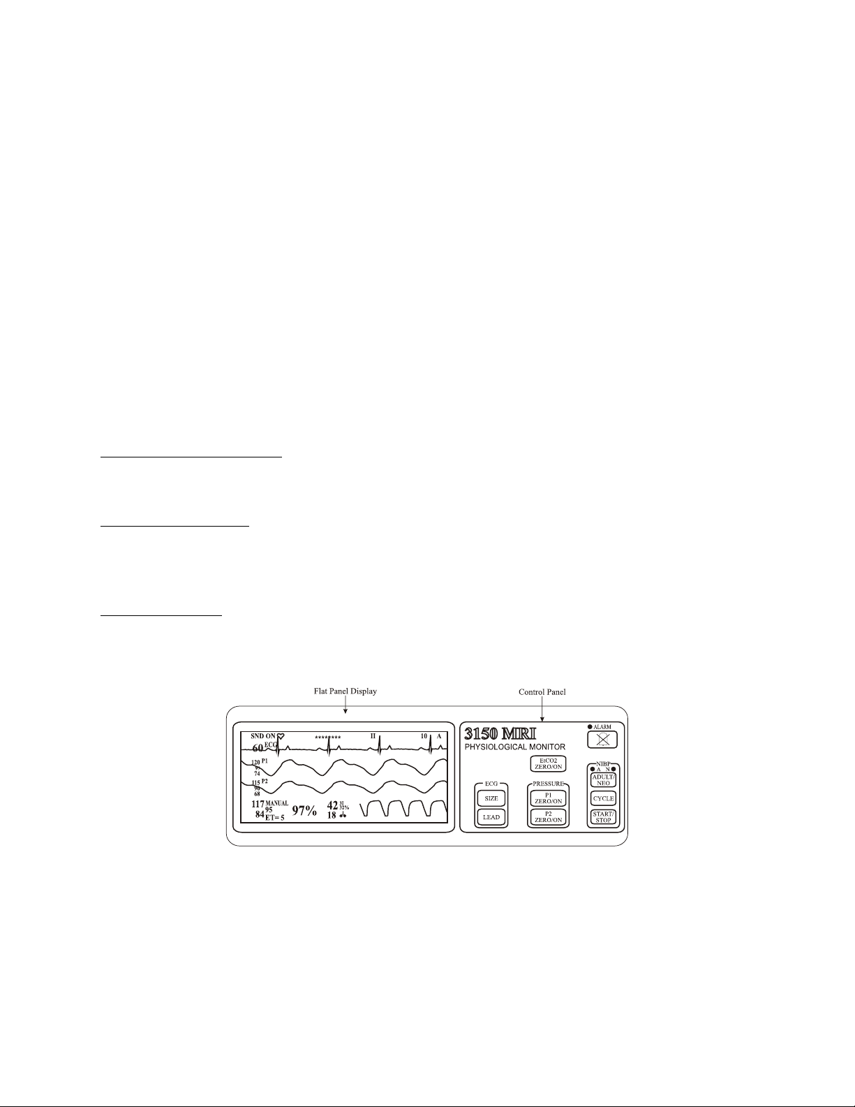
Figure 1-1. 3150(M) MRI Monitor Top Panel
1.4 Top Panel. (See Figure 1-1) The 3150(M) MRI Monitor has limited control of the
parameters which it monitors. Primary control is provided by the Remote Monitor. The Top Panel
of the 3150(M) MRI Monitor consists of a Flat Panel Display and a Control Panel. The Flat Panel
Display provides clear and accurate waveforms of monitored parameters. The Control Panel has
nine control keys to provide secondary control over some of the features of this monitor.
1-2
 Loading...