

Invivo MagnitudeTM 3150M, Omni-TrakTM 3150 User manual


Invivo Research, Incorporated
MagnitudeTM 3150M MRI Monitor
Omni-TrakTM 3150 MRI Monitor
Service Manual
INVIVO
RESEARCH
INCORPORATED
12601 Research Parkway
Orlando, FL 32826
1-800-331-3220
1-407-275-3220
www.invivoresearch.com


TABLE OF CONTENTS
Paragraph Number Page Number
List of Figures ............................................................... iv
General Service Precautions ....................................................v
MRI Service Precautions ...................................................... vi
User Responsibility ......................................................... viii
1.0 THEORY OF OPERATION ............................................. 1-1
1.1 ECG ISO Board AB86 ................................................... 1-1
1.2 ECG Analog Non-ISO Board AB87 ......................................... 1-1
1.3 Invasive Pressure ISO Board AB89 ......................................... 1-1
1.4 Invasive Pressure Non-ISO Board AB90 ..................................... 1-1
1.5 Interconnect Board AB75 ................................................. 1-2
1.6 Pneumatics Box AP45A .................................................. 1-2
1.7 Power Supply Board (AB76 Configuration) ................................... 1-2
1.7.1 Battery Charger .................................................. 1-2
1.8 Power Supply Board (AB152 Configuration) .................................. 1-3
1.8.1 Battery Charger .................................................. 1-3
1.9 MRI Gating/Analog AB116 (Option) ........................................ 1-5
1.10 Oximeter Board AB22 ................................................... 1-5
1.10.1 Isolation Section ................................................. 1-5
1.11 Mother Board AB67M ................................................... 1-5
1.11.1 Non-Invasive Blood Pressure (NIBP) Pump Circuitry .................... 1-5
1.11.2 NIBP Clock ..................................................... 1-6
1.11.3 Front Overlay Interface Circuitry .................................... 1-6
1.12 Signal Processor Board AB47 .............................................. 1-6
1.13 Master Processor AB119 .................................................. 1-6
1.13.1 Microprocessor .................................................. 1-6
1.13.2 Random Access Memory (RAM) .................................... 1-6
1.13.3 Read Only Memory (ROM) ......................................... 1-6
1.13.4 Input/Output Circuitry ............................................. 1-6
1.13.5 Audible Tones and Alarms ......................................... 1-6
1.14 Non-Invasive Blood Pressure (NIBP) Board AB06DJ ........................... 1-6
1.14.1 Microprocessor .................................................. 1-6
1.14.2 Analog to Digital Converter ........................................ 1-6
1.14.3 Programmable EPROM ............................................ 1-6
1.14.4 Pump and Valve Control ........................................... 1-6
1.14.5 Transducer ...................................................... 1-7
1.14.6 Adult Mode ..................................................... 1-7
1.14.7 Neonatal Mode .................................................. 1-7
1.14.8 Over-Pressure Switch ............................................. 1-7
1.15 End Tidal CO2 (ETCO2) Option ........................................... 1-7
1.15.1 Normal Operation ................................................ 1-7
1.15.2 ETCO2 Zero .................................................... 1-8
1.15.3 ETCO2 Occlusion ................................................ 1-8
2.0 CALIBRATION AND VERIFICATION ................................... 2-1
2.0.1 Required Test Equipment. .......................................... 2-1
2.0.2 ETCO2 Test Equipment ........................................... 2-1
2.0.3 GATING Test Equipment .......................................... 2-1
2.1 Turning The Monitor On .................................................. 2-1
i

TABLE OF CONTENTS
Paragraph Number Page Number
2.2 Front Panel Control Verification ............................................ 2-2
2.2.1 ECG Control Keys Verification ...................................... 2-2
2.2.2 ETCO2 ZERO/ON Control Key Verification ........................... 2-3
2.2.3 Invasive Pressure Control Keys Verification ............................ 2-3
2.2.4 ALARM Cont rol Key Verification ................................... 2-3
2.2.5 NIBP Control Keys Verification ..................................... 2-3
2.3 Patient Parameter Verification ............................................. 2-4
2.3.1 ECG Verification ................................................. 2-4
2.3.2 NIBP Verification ................................................ 2-6
2.3.3 SpO2 Verification ................................................ 2-9
2.3.4 ETCO2 Verification .............................................. 2-10
2.3.5 Invasive Pressure Verification ...................................... 2-11
2.3.6 Gating Verification .............................................. 2-12
3.0 DISASSEMBLY PROCEDURES. ......................................... 3-1
3.0.1 Required Tools. .................................................. 3-1
3.1 Printed Circuit Board and Battery Access .................................... 3-1
3.1.1 AS145 Electronics Assembly (Card Cage) Removal ..................... 3-1
3.2 Low Battery Circuit. ..................................................... 3-4
4.0 ADJUSTMENT PROCEDURES ......................................... 4-1
4.1 Introduction ............................................................ 4-1
4.2 Setup ................................................................. 4-1
4.3 Power Supply Calibration (AB76 Power Board Only) ........................... 4-2
4.4 Power Supply Calibration (AB152 Power Board Only) .......................... 4-4
4.5 LCD Module Intensity Adjustment .......................................... 4-6
4.6 Speaker Volume Adjustment (Model 3150M Monitor Only) ...................... 4-6
4.7 Signal Processor Reference Voltage Adjustment ............................... 4-6
4.8 NIBP Adjustments ...................................................... 4-7
4.9 ECG Amplifier Adjustments .............................................. 4-10
4.10 Invasive Pressure Adjustments ............................................ 4-11
4.11 ETCO2 Adjustment .................................................... 4-13
4.12 Gating Adjustment ..................................................... 4-14
5.0 PROGRAMMING INSTRUCTIONS ...................................... 5-1
5.1 Introduction ............................................................ 5-1
5.2 Required Test Equipment ................................................. 5-1
5.3 Setup ................................................................. 5-1
5.4 HE60 Programming for Single 3155 Communications .......................... 5-2
5.5 HE60 Programming for 3155/AS163 Communications .......................... 5-4
5.6 HE60 Programming for Dual 3155 Communications ............................ 5-6
6.0 CONFIGURATION SCREEN ............................................ 6-1
6.1 Introduction ............................................................ 6-1
6.2 Standard Configuration ................................................... 6-1
6.3 P1 and P2 ............................................................. 6-1
6.4 ETCO2 ............................................................... 6-1
6.5 ETCO2 Units .......................................................... 6-1
6.6 3150 Model ............................................................ 6-1
6.7 Language .............................................................. 6-2
ii

TABLE OF CONTENTS
Paragraph Number Page Number
APPENDIX A. WIRING BREAKOUT DIAGRAMS ............................ A-1
APPENDIX B. LIST OF SYMBOLS ...........................................B-1
iii

LIST OF FIGURES
Figure Number Page Number
Figure 1-1. ETCO2 Flow Diagram - Normal Operation .............................. 1-7
Figure 1-2. ETCO2 Flow Diagram - Zero ........................................ 1-8
Figure 1-3. ETCO2 Flow Diagram - Occlusion .................................... 1-9
Figure 2-1. The 3150/3150M Monitor Control Panel ................................ 2-2
Figure 3-1. Card Cage Removal Diagram ......................................... 3-2
Figure 3-2. Software Location Diagram (AB06DJ, AB22M, AB47 and AB119) .......... 3-3
Figure 3-3. Software Location Diagram (AB115 ETCO2 Board) ...................... 3-4
Figure 3-4. AB67M Location Diagram ........................................... 3-4
Figure 4-1. Power Supply Test Setup ............................................ 4-2
Figure 4-2. TF0088/TF0082 Assembly Instructions ................................. 4-4
Figure 4-3. AB06DJ Transducer Input Cable ...................................... 4-8
iv

GENERAL SERVICE PRECAUTIONS
Obtain a thorough understanding of each of the following precautions before attempting to
perform any disassembly or service procedure. Damage to the instrument or injury to yourself
may result if these precautions, as well as common sense, are not used.
Service to this product should only be performed by trained, qualified service personnel familiar with
the operation and service documentation for this monitor.
Shock Hazard exists when this monitor is operated without the chassis cover. Use caution when
working on units with power applied.
Always disconnect monitor from AC Main Power before performing service on internal assemblies.
Due to the monitor's internal battery, power may be present even when disconnected from the AC
Main Power. When necessary, disconnect the internal battery prior to performing service or shipping
the system to the manufacturer for repair.
Replace fuses with same type and rating only.
Always follow proper electrostatic discharge (ESD) procedures during component and assembly
handling to prevent static discharge damage to sensitive parts.
Use only replacement parts specified in this manual.
When cleaning the unit, do not permit liquid to enter the case. When cleaning, use proper materials
and ensure total dryness before powering the monitor. Use care that cleaning fluids do not attack
plastic or painted surfaces. Use care that wiping rags do not abrade the surfaces.
Assembly hardware has been secured with a thread locking agent. After several
assembly/disassembly cycles new locking agent will be required. (Use Loctite 42540 or similar type
for use near PVC or acrylic plastics.)
In general, handle all Printed Circuit Boards by their edges. Oils, sweat, dirt, etc. can induce leakage
paths in high impedance circuits which impede their operation. Such contamination will also
promote corrosion of circuits yielding a long term reliability problem.
Avoid rough handling of all exposed chassis parts and front panel overlay. These parts can be
scratched causing obtrusive cosmetic defects.
This system is intended for use in the Magnetic Resonance Imaging (MRI) areas. Use only nonferrous or non-magnetic replacement parts in the monitor.
v

MRI SERVICE PRECAUTIONS
NOTE
In addition to these precautions, cautions and warnings are located in
paragraphs 4.0 (Page 4-1) and 4.8 (Page 4-9).
CAUTION
Federal law in the USA and Canada restricts this device to sale by, or on the
order of, a licensed medical practitioner.
This monitor is not intended for use in the presence of FLAMMABLE ANESTHETICS. An
explosion hazard exists.
Never immerse the monitor in any fluid or attempt to clean it with liquid cleaning agents. An
electrical hazard exists.
Do not remove the monitor's cover. A shock hazard exists. Refer servicing to qualified personnel
only. No repair should be undertaken or attempted by anyone not having a thorough understanding
of the repair and safety assurance of patient monitors.
Risk of RF current burn. Cables which become inadvertently looped during MRI act as conductive
lines for RF induced currents. When lead wires or other cables form conductive loop in contact with
the patient's tissue, minor to severe burning can result.
Perform the following to minimize risk of RF current burn:
1. Place cables and lead wires neatly in straight alignment with no looping.
2. Keep the length of lead wires and patient cable within the bore to a minimum.
3. RF burn risk increases when multiple sensors/cables are in use. Such combinations
are not recommended.
4. The high radio frequency (RF) power used in MR scanning poses an ever-present risk
of excessive heat at the monitoring sites and, therefore, the risk of RF current burn.
Should power levels greater than S.A.R. of 4 w/kg peak (0.4 w/kg average) be
used, the risk of patient burn greatly increases. As a result, monitoring of ECG or
Respiration (derived from ECG leads) at power levels of greater than 4 w/kg peak (0.4
w/kg average) is not recommended for the general patient population. Such
monitoring should only be attempted on conscious patients with good temperature
reflex so they may warn the operator of excessive heat at the monitoring sites.
5. High RF Power may cause patient heating or burns. For scans with average
S.A.R. > 1 w/kg, limit scan time to 5 minutes and pause at least 3 minutes
between scans to allow ECG Cable to cool.
NOTE
Use only Invivo Research Fiber Optic Sensors and other MRI
Compatible accessories with this monitor.
vi

MRI Compatibility
The QuadtrodeTM MRI ECG Electrode Pad, and ECG Patient Lead Wires and Cable,
are compatible with Magnetic Resonance Imaging (MRI) Systems within the following
guidelines:
! MRI Systems with static magnetic field strengths up to 1.5 Tesla.
! Usable within the MRI system bore with Specific Absorption Ratios (S.A.R.'s)
up to 4.0 w/kg (peak). Use with higher S.A.R.'s greatly increases the risk of
patient burns.
! Non-magnetic materials are used in the construction of these assemblies.
! If scanned directly across the plane of the ECG electrode element, a slight image
distortion may be seen at the skin surface where the electrode element is
positioned.
vii

USER RESPONSIBILITY
This product will perform in conformity with the description contained in the Operations Manual
for the Omni-TrakTM 3150/MAGNITUDETM 3150M MRI Monitor (IRI Part Number 9538) and
accompanying labels and/or inserts, when assembled, operated, maintained, and repaired in
accordance with the instructions provided. This product must be checked and calibrated
periodically. Recommended calibrations should be performed every six months. Operational checks
should be done with each use.
A defective product should not be used. Parts that are broken, missing, plainly worn, distorted, or
contaminated should be replaced immediately. Should such repair or replacement become necessary,
Invivo Research, Incorporated (IRI) recommends that a telephone call or written request for service
be made to the nearest factory service center. This product or any of its parts should not be repaired
other than in accordance with written instructions provided by IRI or altered without the prior written
approval of IRI. The user of the product shall have the sole responsibility for any malfunction which
results from improper use, faulty maintenance, improper repair, damage, or alteration by anyone
other than IRI authorized service personnel.
There are no user maintenance requirements. All maintenance requirements are to be done by
qualified Service Personnel only.
viii

SECTION I
THEORY OF OPERATION
1.0 THEORY OF OPERATION
1.1 ECG ISO Board AB86. A 40 KHZ reference signal, supplied by the ECG Analog board,
is fed through T1 then rectified and filtered in the ISO power metal box for the + and - 12V ISO
supplies.
ECG lead surge protection is provided by surge arresters LP 1-5. Additional protection and signal
conditioning is provided by U2, U3 and associated circuitry.
Lead selection is provided by U14,U15,U16, U4,U5,U7 and U8. RL drive is selected by U1 and
associated circuitry.
U9 and associated circuitry provide amplification and filtering for stabilization of the channel 1
signal before passing through ISO Barrier U12. U23 and associated circuitry provide the proper DC
offset before the signal is sent to the ECG Analog Board.
U10 and associated circuitry provide amplification and filtering for stabilization of the channel 2
(CAL) signal before passing through ISO Barrier U24. U23 and associated circuitry provide the
proper DC offset before the signal is sent to the ECG Analog Board.
1.2 ECG Analog Non-ISO Board AB87. Channel 1 ECG signal is again filtered and amplified
to 1V per 1mv by U20, U32, U42 and associated circuitry. Channel 2 ECG signal is again filtered
and amplified to 1V per 1mv by U20, U26, U22 and associated circuitry. Both channels are fed into
U1 then sent to the AB47 Signal Processor board.
A 40 KHZ crystal is amplified and used for ISO power reference (T1.5). It is also used as a clock
where after divided by U8 and U3 a 1.22 HZ CAL signal is generated. Lead selection and RL drive
are driven by U2.
1.3 Invasive Pressure ISO Board AB89. A 40 KHZ reference signal, supplied by the Invasive
Pressure Non- ISO board, is fed through T1 then rectified and filtered in the ISO power metal box
for the + and - 12 Vdc ISO supplies. U7 and associated circuitry provide regulation for the 1.53 Vdc
transducer excitation reference voltage.
U1, U2, U5 and associated circuitry provide amplification and signal conditioning before passing
through ISO Barrier U6 and U10. The output gain and DC zero offset are controlled by U3 and
associated circuitry.
Later versions of this board include a slew rate filter circuit. The slew filter extracts pressure signals
in the presence of large MR gradient pulses. This function is provided by U4, U12, U13 and U14.
DC shift caused by this interference is neutralized by R69 (Channel 1) and R45 (Channel 2).
1.4 Invasive Pressure Non-ISO Board AB90. P1 and P2 signals are received from the Invasive
pressure ISO board AB89, and filtered by U4, U5 and associated circuitry.
U7 - U10 provide 8 bit D-A conversion along with U11, I/O parallel programmable CMOS.
A 40 KHZ crystal is amplified and used for ISO power reference (T1.5).
1-1

1.5 Interconnect Board AB75. The AB75 provides interconnections for the LCD Module
Display, backlight, Alarm speaker, ON/OFF switch and keypad. It also houses the Adult, Neo, Alarm
drivers and LEDs.
1.6 Pneumatics Box AP45A. The AP45A Pneumatics Box houses the NIBP pump, Humphrey
valve, NIBP overpressure valve, EtCO2 pump and pneumatic valves. It also houses the LCD display
backlight inverter which converts 5 Vdc to approximately 900 VAC for the LCD backlight supply
voltage.
1.7 Power Supply Board (AB76 Configuration). In the AB76 configuration, power is supplied
to this monitor’s operational circuits by the AB76 Power supply board.
The +5 Vdc supply is regulated by a DC to DC converter U6 and its related circuitry.
The +12 Vdc supply is regulated by U5. When in battery operation Q4 turns on switching regulator
U7 to boost the voltage maintaining sufficient U5 input regulator voltage.
The -12 Vdc supply is regulated by DC to DC converter U4 and its related circuitry.
The +10 Vdc supply is regulated by U3 using the +12 Vdc supply as reference.
1.7.1 Battery Charger. The battery charger is comprised of VR1, U1, Q3, Q6, Q7, Q8 and
associated components. Components VR1, R39, R7, D29, D35, D30 and C41 form an adjustable
voltage reference which is adjusted by R6 to the maximum battery charge voltage. The diodes, D29,
D35 and D30 are located in the reference leg of VR3 to provide temperature compensation for the
battery. C41 provides output voltage stability for the adjustable voltage reference output. U1 and
associated components C43, C44, D27, D28, R29, R35, R36, R42, R44 and R47 form a two stage
voltage comparator which is used to monitor battery voltage and control the charger switching
circuit.
Resistors R29 and R47 form a voltage divider with a nominal voltage of 8.1 Vdc (which represents
an undervoltage battery condition) and is applied to U1-3. Resistor R36 applies the battery voltage
to the other side of the undervoltage comparator at U1-2. Resistor R45 connects the output of the
undervoltage comparator U1-1 back to the positive input of the undervoltage comparator where it
is used to provide approximately 80mV of hysteresis about the comparator threshold. This results
in circuit stability when the battery undervoltage crossover point is present. The output of the battery
undervoltage comparator is low (less than 1.5 Vdc) under normal battery conditions and does not
affect the operation of the second (over-voltage) comparator.
When an undervoltage battery condition is detected the comparator output will be high and will be
applied through D27 to U1-6 where it will override the high impedance battery input and result in
the battery charger being turned off. The present battery voltage is also applied through R35 to U1-6
as a high impedance input. C44 filters this voltage for stability during comparator crossover
conditions.
The adjustable battery reference voltage is applied to the other side of the high battery voltage
comparator at U1-5 through R44. The output of the high battery voltage comparator occurs at U1-7
and is applied to the battery charger switching circuit. Resistor R42 provides approximately 30mVdc
of negative hysteresis for stability as the battery approaches a fully charged condition.
The output of the high battery voltage comparator at U1-7 will be high when the battery terminal
voltage is between 5.2 and the battery reference voltage as set at the output of VR3 (normally 14.84
Vdc). Capacitor C43 is a filter at the positive power terminal of U1. Diode D28 clamps the input
1-2

at U3-6 to a value no greater than Vcc +0.7 Vdc to provide a low impedance discharge path for C44
during input power down condition.
When the output of the battery comparators i s high, the battery charger switching circuit will be
turned on. A voltage of less than 17.0 Vdc will be present at the emitter of transistor Q6 and not
enough current can flow through resistors R4, R33 and across diode D25 to cause transistor Q6 to
saturate.
The voltage at the base of transistor Q7 will cause Q7 to conduct current through resistors R21, R34,
R8 and across diode D2 into the battery. This will turn on transistor Q8 and apply a forward bias
to the base of transistor Q3, turning Q3 on. Capacitor C46 will delay slightly the turn on (and turn
off) time of transistor Q8. When transistor Q3 is turned on, current will flow into L1, C36, across
resistor R9 and through diode D2 into the battery.
When approximately 1.0 ampere of current is flowing through resistor R9, a voltage large enough
to turn on transistor Q5 will be developed (0.65 Vdc). Resistor R20 limits the base current of Q5.
When Q5 is saturated the voltage across the emitter-base junction of transistor Q7 will fall below
the level required for conduction and Q7 will turn off. Transistors Q8 and Q3 will be turned off.
Current will continue to flow into the battery through diode D20, L1, R9 and D2 due to the field
collapse of coil L1. Capacitor C36 will also provide a current source at this time. When current
flowing out of coil L1 and capacitor C36 is no longer sufficient to maintain a voltage saturating the
emitter-base junction of transistor Q5, transistor Q7 will turn on and the cycle will repeat. The cycle
frequency is determined by the LC time constant of L1 and C36 and is approximately 8.4 KHz.
When the battery is sufficiently charged, the voltage to the battery comparators becomes positive
enough to allow the output to switch low at U1-7. Enough current then flows through R4, R33 and
diode D25 to turn on transistor Q6 and transistor Q7 is held in the cutoff condition until further
charging is required.
1.8 Power Supply Board (AB152 Configuration). In the AB152 configuration, power is
supplied to this monitor’s operational circuits by the AB152 Power supply board.
The +5 Vdc supply is regulated by a DC to DC converter U6 and its related circuitry.
The +12 Vdc supply is regulated by U5. When in battery operation Q4 turns on switching regulator
U7 to boost the voltage maintaining sufficient U5 input regulator voltage.
The -12 Vdc supply is regulated by DC to DC converter U4 and its related circuitry.
The +10 Vdc supply is regulated by U3 using the +12 Vdc supply as reference.
1.8.1 Battery Charger. The battery charger is comprised of VR1, U1, Q3, Q6, Q7, Q8 and
associated components. Components VR1, R39, R7, D29, D35, D30 and C41 form an adjustable
voltage reference which is adjusted by R6 to the maximum battery charge voltage. The diodes, D29,
D35 and D30 are located in the reference leg of VR3 to provide temperature compensation for the
battery. C1 provides output voltage stability for the adjustable voltage reference output. U1 and
associated components C43, C44, D27, D28, R29, R35, R36, R42, R44 and R47 form a two stage
voltage comparator which is used to monitor battery voltage and control the charger switching
circuit.
Resistors R29 and R47 form a voltage divider with a nominal voltage of 7.9 Vdc (which represents
an undervoltage battery condition) and is applied to U1-3. Resistor R36 applies the battery voltage
to the other side of the undervoltage comparator at U1-2. Resistor R45 connects the output of the
undervoltage comparator U1-1 back to the positive input of the undervoltage comparator where it
1-3

is used to provide approximately 80mV of hysteresis about the comparator threshold. This results
in circuit stability when the battery undervoltage crossover point is present. The output of the battery
undervoltage comparator is low (less than 1.5 Vdc) under normal battery conditions and does not
affect the operation of the second (over-voltage) comparator.
When an undervoltage battery condition is detected the comparator output will be high and will be
applied through D27 to U1-6 where it will override the high impedance battery input and result in
the battery charger being turned off. The present battery voltage is also applied through R35 to U1-6
as a high impedance input. C44 filters this voltage for stability during comparator crossover
conditions.
The adjustable battery reference voltage is applied to the other side of the high battery voltage
comparator at U1-5 through R44. The output of the high battery voltage comparator occurs at U1-7
and is applied to the battery charger switching circuit. Resistor R42 provides approximately 2.2 Vdc
of negative hysteresis for stability as the battery approaches a fully charged condition.
The output of the high battery voltage comparator at U1-7 will be high when the battery terminal
voltage is between 5.2 and the battery reference voltage as set at the output of VR3 (normally 14.5
Vdc). Capacitor C43 is a filter at the positive power terminal of U1. Diode D28 clamps the input
at U1-6 to a value no greater than Vcc +0.7 Vdc to provide a low impedance discharge path for C44
during input power down condition.
When the output of the battery comparator is high, the battery charger switching circuit will be
turned on. A voltage of less than 17.0 Vdc will be present at the emitter of transistor Q6 and not
enough current can flow through resistors R4, R32 and across diode D25 to cause transistor Q6 to
saturate.
The voltage at the base of transistor Q7 will cause Q7 to conduct current through resistors R21, R34
and R8 into the battery. This will turn on transistor Q8 and apply a forward bias to the base of
transistor Q3, turning Q3 on. Capacitor C46 will delay slightly the turn on (and turn off) time of
transistor Q8. When transistor Q3 is turned on, current will flow into L1, C36, across resistor R9
and through diodes D14, D15, D16 and D17 into the four batteries.
When approximately 1.0 ampere of current is flowing through resistor R9, a voltage large enough
to turn on transistor Q5 will be developed (0.65 Vdc). Resistor R20 limits the base current of Q5.
When Q5 is saturated the voltage across the emitter-base junction of transistor Q7 will fall below
the level required for conduction and Q7 will turn off. Transistors Q8 and Q3 will be turned off.
Current will continue to flow into the battery through diode D20, L1, R9 and D2 due to the field
collapse of coil L1. Capacitor C36 will also provide a current source at this time. When current
flowing out of coil L1 and capacitor C36 is no longer sufficient to maintain a voltage saturating the
emitter-base junction of transistor Q5, transistor Q7 will turn on and the cycle will repeat. The cycle
frequency is determined by the LC time constant of L1 and C36 and is approximately 8.4 KHz.
When the battery is sufficiently charged, the voltage to the battery comparators becomes positive
enough to allow the output to switch low at U1-7. Enough current then flows through R4, R33 and
diode D25 to turn on transistor Q6 and transistor Q7 is held in the cutoff condition until further
charging is required.
Each of the four batteries has its own diode for charge and discharge. This helps prevent a battery
with a dead cell from discharging the other batteries.
A battery protection circuit consisting of U2 and associated components, and Q12 is used to prevent
deep discharge of the batteries. If the battery output voltage, DC_PRESENT, drops below +10 Vdc,
U2-1 will go high turning off Q12. In this state, the load on the batteries is reduced to less than 1mA
1-4

to avoid a deep discharge condition. Then, if external power of +15 Vdc or greater is applied, U2-1
will go low enabling Q12 to pass main power.
1.9 MRI Gating/Analog AB116 (Option). Printed circuit board assembly part number AB116
provides both analog signals as well as TTL pulses to the MRI gating output connector on the base
of the Model 3150/3150M. See Volume II - AC356 for pin description.
The circuit composed of U5 (Digital-to-Analog Converter), U6, and U8 provide analog signal
outputs. These analog signals include both low and high amplitude ECG signals, high level invasive
pressure (P1) signal, high level respiration (from ETCO2) signal, and low and high amplitude pulse
signals. The low and high amplitude pulse signals are selected by the position of JMP1. When the
jumper is set between pins 1 and 2 the high level signal is output and, likewise, when set between
pins 2 and 3 the low level signal is output. U7A and its related components provide the reference
voltage to U5 (DAC).
The network of U1, U2, and U3 provides TTL outputs corresponding to the peaks of the heart rate
(HR) source signal, invasive pressure 1 (P1), respiration(from ETCO2), and pulse signal. The HR
source signal is software selectable through the HR source selection in the ECG menu of the Model
3155MVS/3155A. The TTL pulses have an amplitude between 3.3 and 5.0 Vpp and a duration of 13
±3 ms.
1.10 Oximeter Board AB22. The AB22 Board contains the Oximeter Processor Circuitry. This
board contains the hardware necessary to control the Oximeter System Operation, it performs the
Timing and Measurement Operations using Counter Timers (82C53) under the control of the
microprocessor, provides for Data Memory Storage (with data provided by a 32K by 8 bit ROM and
an 8K by 8 bit static RAM) and interfaces with the Signal Processor and Master Processor Ports.
1.10.1 Isolation Section. The Oximeter Analog Section provides patient input parameter
measurement and patient isolation. The isolated section consists of four functional circuit elements:
timing and control, LED drive, the receiver/amplifier and ramp comparator circuits.
a. The timing and control circuits perform system timing functions that maintain
synchronic action between the LED drive, signal comparator and demodulator circuits.
b. The LED drive section contains two drive level integrators, a drive signal multiplexer
and a differential drive amplifier to control the intensity of the red and IR LED's
contained in the particular SpO2 sensor.
c. The receiver/amplifier consists of a two stage, high gain, bandpass receiver amplifier
followed by a pair of demodulators and three pole low pass filters for signal recovery
and processing.
d. The ramp and comparator circuits consist of a precision 10.00 Vdc reference, a
precision ramp generator, analog sampling switches and three comparators used to
detect voltage crossover levels for timing comparisons.
1.11 Mother Board AB67M. The Mother Board contains the connectors which interface the
major assemblies of the monitor together. In addition, this board also houses the Non-Invasive
Blood Pressure (NIBP) pump circuitry, NIBP Clock, front overlay interface circuitry, low battery
shutoff reference divider and communications driver.
1.11.1 Non-Invasive Blood Pressure (NIBP) Pump Circuitry. Q1 drives the NIBP Pump with the
drive signal provided by the NIBP board (AB06DJ). The pump signal varies according to whether
the monitor is set in the Adult or Neonatal NIBP mode. In the Adult mode the pump drive signal
1-5

is a DC voltage whereas in the Neonatal mode the signal is pulse width modulated. Q2 provides a
current limit for the pump drive.
1.11.2 NIBP Clock. X1 supplied the 4 MHz for the AB06DJ and U6 divides it by 2 to supply the
2MHz Clock.
1.11.3 Front Overlay Interface Circuitry. The combination of pull up resistors (R7, R8, R9 and
R10A through F), diodes (D9, D10, D11, Z1, Z2 and Z3), and front overlay make up the matrix that
interface the membrane switches to the master processor.
1.12 Signal Processor Board AB47. The Signal Processor receives analog signals from the ECG,
ETCO2, Invasive Pressure and SpO2 boards via the Input/Output ports and converts the analog
signals to a digital format for analysis at the Master Processor and display. The Signal Processor
also sends commands to the parameter boards through these Input/Output ports.
1.13 Master Processor AB119. The Master Processor board contains the microprocessor,
supporting Random Access Memory (RAM), Read Only Memory (ROM), Input/ Output circuitry,
and audio tone and alarm circuitry.
1.13.1 Microprocessor. The Master Processor utilities a 64180 microprocessor at location U7 and
related circuitry for the processing of patient data for analysis and display.
1.13.2 Random Access Memory (RAM). U15, U18, and U19 contain Random Access Memory
(RAM) for use by the microprocessor when executing instructions.
1.13.3 Read Only Memory (ROM). U18 and U19 contain Erasable/Programmable ROM (EPROM)
which contain the operating instructions to be used by the processor for monitor operations.
1.13.4 Input/Output Circuitry. Input/ Output circuitry at locations U20 through U22 interface the
Master Processor to the parameter boards, Signal Processor, and other peripheral devices.
1.13.5 Audible Tones and Alarms. The combination of U8, U16, and U 32 provide the audible
tones and alarms.
1.14 Non-Invasive Blood Pressure (NIBP) Board AB06DJ. The NIBP board contains the
circuitry for obtaining Adult and Neonatal non-invasive blood pressure. The board receives an input
signal from the pressure transducer which contains the oscillometric signal. This signal is amplified
and filtered and used to determine the NIBP readings. In addition the board provides outputs to
control the NIBP pump and valve assemblies.
1.14.1 Microprocessor. The NIBP board utilizes a Z80 4MHZ processor (location U14) that
communicates directly to the Master Processor through the Input/Output ports at locations U10 and
U12.
1.14.2 Analog to Digital Converter. U9 is a six channel A to D converter with inputs from the overpressure switch, fail-safe timer, +5.12 reference voltage, Adult oscillometric signal, Neonatal
oscillometric signal, and pressure signal.
1.14.3 Programmable EPROM. U12 contains the operating instruction and algorithm for NIBP
operation.
1.14.4 Pump and Valve Control. The pump and valve drive signals are developed at the
microprocessor and output through Input/Output ports at location U12.
1-6
1.14.5 Transducer. The transducer is pneumatically attached to the to the sense port at the monitors
column assembly. The pneumatic pressure along with the oscillometric signal is converted to analog
signals and routed directly to the NIBP board where it is amplified and filtered for analysis.
1.14.6 Adult Mode. When the front panel indicator shows Adult the pump will run at a higher speed
and the gain and filtering of the oscillometric signal amplifiers are set accordingly. The processor
uses the digitized Adult oscillometric signal from the A to D converter for making blood pressure
determinations.
1.14.7 Neonatal Mode. When the front panel indicator shows Neonatal the pump drive signal is
pulse width modulated and the gain and filtering of the oscillometric signal amplifiers are set
accordingly. The processor uses the digitized Neonatal oscillometric signal from the A to D
converter for making the blood pressure determination.
1.14.8 Over-Pressure Switch. The over-pressure switch is located on the side of the Pneumatics Box
(AP45). It is a mechanical switch that is set to interrupt the NIBP function when pressure in the
pneumatic section exceed 270 mmHg.
1.15 End Tidal CO2 (ETCO2) Option. The End Tidal CO2 (ETCO2) option is divided among
two assemblies. The ETCO2 electronics is contained on the circuit board assembly part number
AB115. The ETCO2 pneumatic hardware (pump, valve 1, valve 2, and valve 3) are contained in the
pneumatic box part number AP45A.
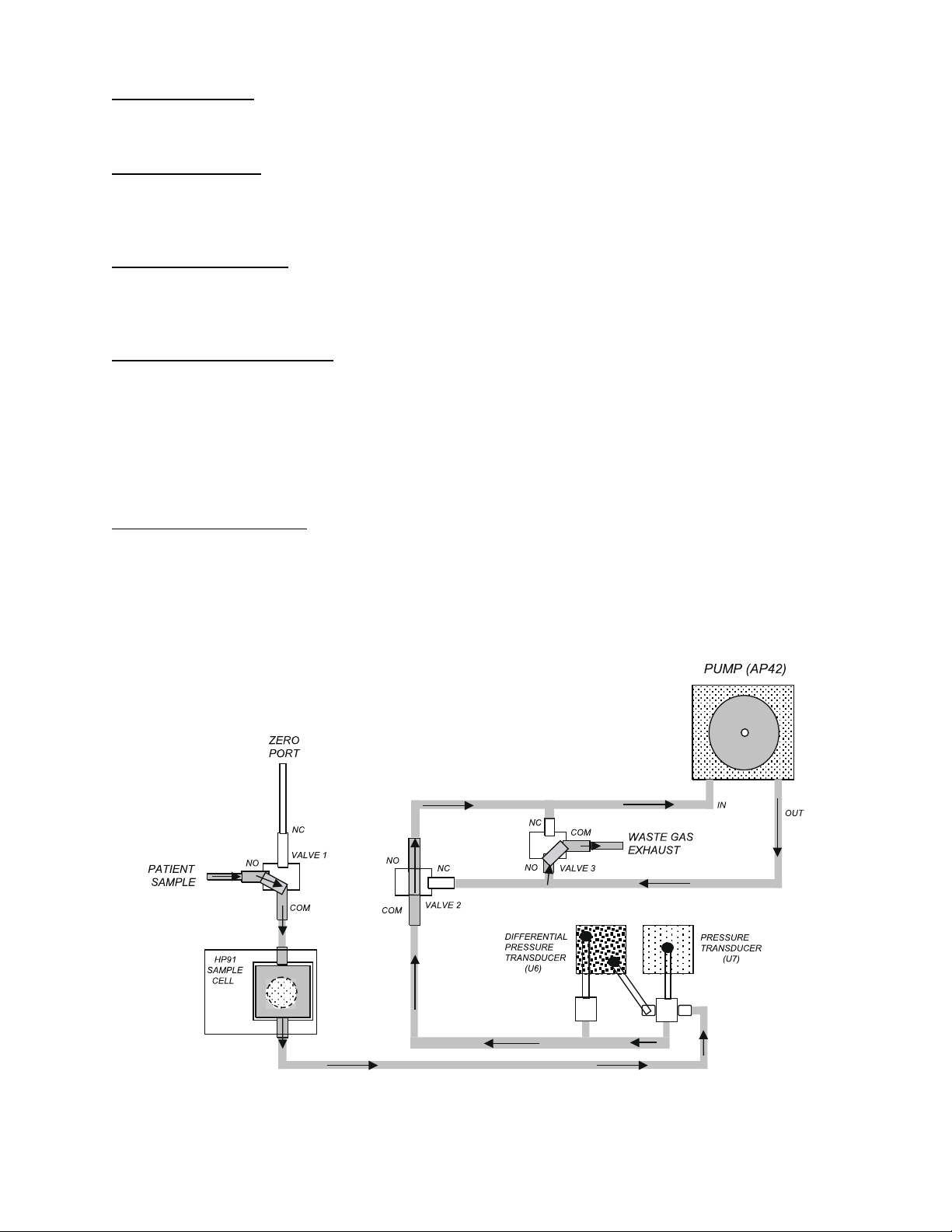
1.15.1 Normal Operation. In the normal operating mode (drawing a sample from the patient sample
port) valve 1 (V1), valve 2 (V2), and valve 3 (V3) are in the normally open (NO) position (See
Figure 1-1). The sample moves from the patient sample port through V1 and into the gas analyzer
(HP91). The gas analyzer uses infrared analysis to provide analog signals that correspond to the
amount of CO2 and N2O present in the sample. Analog signals representing CO2 and N2O along
with a reference signal are multiplexed, digitized and sent to the processor for manipulation,
processing, and display. From the gas analyzer the sample passes to the absolute pressure and
Figure 1-1. ETCO2 Flow Diagram - Normal Operation
1-7
differential pressure sensors. The absolute pressure circuit contains the sensor (U7), a differential
amplifier (U3), and operational amplifier (U4B) and provides a signal that represents the pressure
of the sample. The differential pressure circuit is comprised of the differential pressure sensor (U6)
and operational amplifiers U2 and U4A. The differential pressure transducer signal represents the
flow rate through the system. The absolute and differential signals are multiplexed, digitized and sent
to the processor for manipulation and processing. The sample when moves through V2, through the
pump, through V3 and out the waste gas exhaust port. The processor controls the pump (On/Off and
Adult/Neo) and pump speed through U14 (Input/Output Interface), Q1, Q2, U1, and U5.
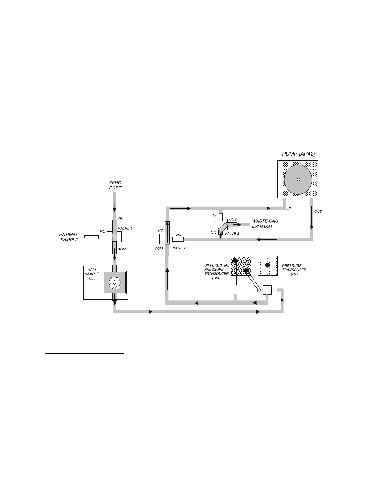
1.15.2 ETCO2 Zero. At various times during operation the system must be zeroed to the
atmosphere in order to eliminate drift in tolerance (See Figure 1-2). During the zeroing process the
processor sends a signal to Q3 which energizes V1 changing it from the NO position to the NC
position. This action causes the sample to be drawn from the zero port (atmosphere) rather than
from the patient sample port. The processor then establishes the zero point at atmosphere.
Figure 1-2. ETCO2 Flow Diagram - Zero
1.15.3 ETCO2 Occlusion. If the pneumatic system should become plugged with debris (occlusion),
the direction of system flow is reversed in order that debris is dislodged from the system. An
occlusion event (See Figure 1-3) is determined by the processor as a drop in the system flow rate as
determined by the differential pressure sensor. When the processor recognizes an occlusion, a signal
is sent to U14 I/O. U14 turns Q3, Q4, and Q5 on which switches V1, V2, and V3 to the NC position.
This reverses the flow of the system and pushes the debris out the zero port.
1-8
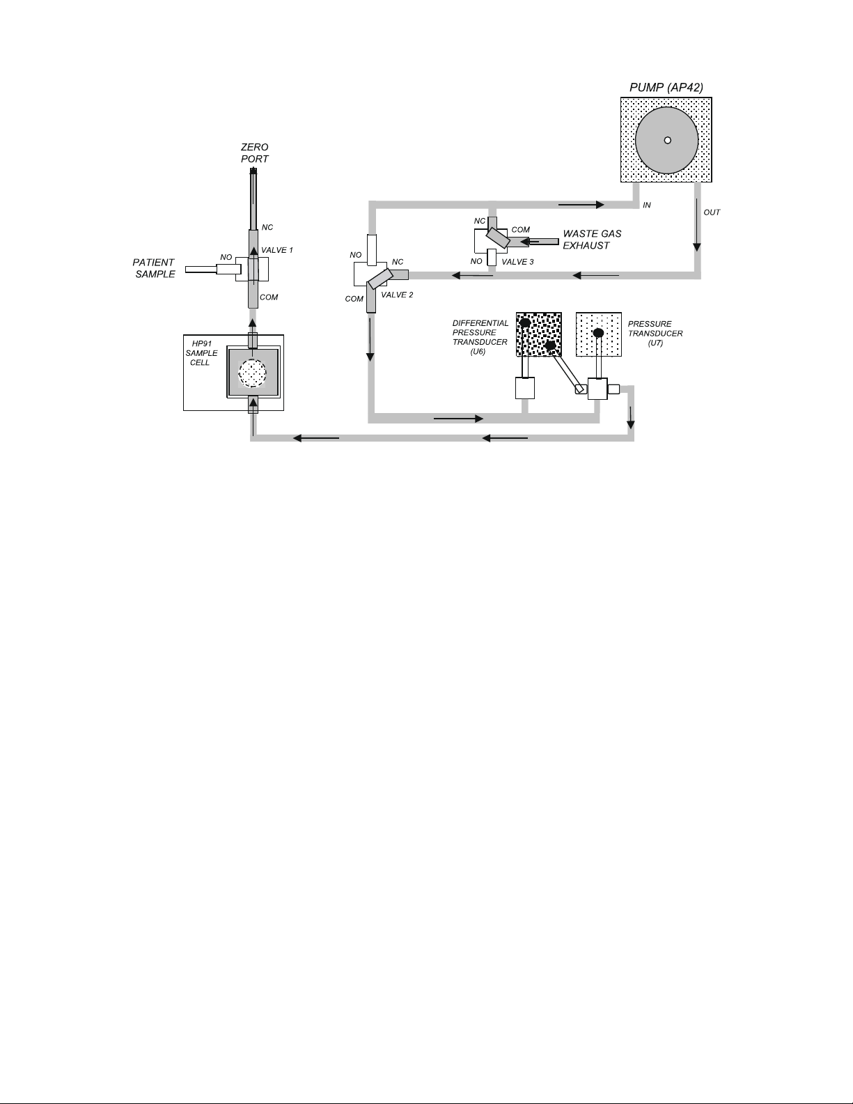
Figure 1-3. ETCO2 Flow Diagram - Occlusion
1-9

[THIS PAGE INTENTIONALLY LEFT BLANK.]
1-10

SECTION II
CALIBRATION AND VERIFICATION
2.0 CALIBRATION AND VERIFICATION
2.0.1 Required Test Equipment. The following test equipment is required to perform calibration,
verification and adjustment procedures on the Model 3150/3150M monitors:
! 20 MHz Dual Channel Oscilloscope (Analog).
! Digital Multimeter (DMM) (5.5 digit accuracy or better).
! Pressure Manometer.
! Patient Simulator (ECG: 60-300 bpm, 0.5 to 2 mV amplitude, 1mV square wave at 2 Hz).
! Variable Auto Transformer (50/60Hz, 120V input, 0-250V output or equivalent).
! Variable DC Voltage Supply.
! 40 foot NIBP Hose.
! Pressure Simulator (0 to 250 mmHg).
! Extender Boards.
! Piece of Wood (2 ft. 1 x 6").
! Signal Generator (50 S Output Impedance).
! 49.9K S Resistor.
! 0.05 mm Hex Driver.
2.0.2 ETCO2 Test Equipment. The following additional test equipment is only required if the
monitor contains the ETCO2 option:
! Air Flow Meter (0 to 300 mL/minute)
! Calibration Gas (10% CO2, 50% N2O, Balance N2, Invivo Research Part Number 9010F)
2.0.3 GATING Test Equipment. The following additional test equipment is only required if the
monitor contains the GATING option:
! Signal Test Adapter, Invivo Research Part Number AS131.
2.1 Turning The Monitor On. Perform the following procedure to apply power to the monitor:
a. Turn the AS153 AC Power Adapter and 3150/3150M monitor Power Switches to the
ON position.
b. On the 3150/3150M monitor Front Panel Display: verify that the following messages are
displayed (alarm tone will also sound):
(1) COMMAND LINK: LOST.
(2) DATA LINK: UNKNOWN.
c. Turn the Millennia® 3155MVS/3155A monitor Power Switch to the ON position.
d. On the 3150/3150M monitor Front Panel Display: verify that the following messages
have been removed from the display:
(1) COMMAND LINK: LOST.
(2) DATA LINK: UNKNOWN.
e. On the Millennia® 3155MVS/3155A monitor, verify the following:
(1) The lower right hand box on the Display Screen is labeled REMOTE.
(2) Both Squares inside the Remote Box are together.
(3) The Status Box is green (indicating proper communications have been established).
2-1
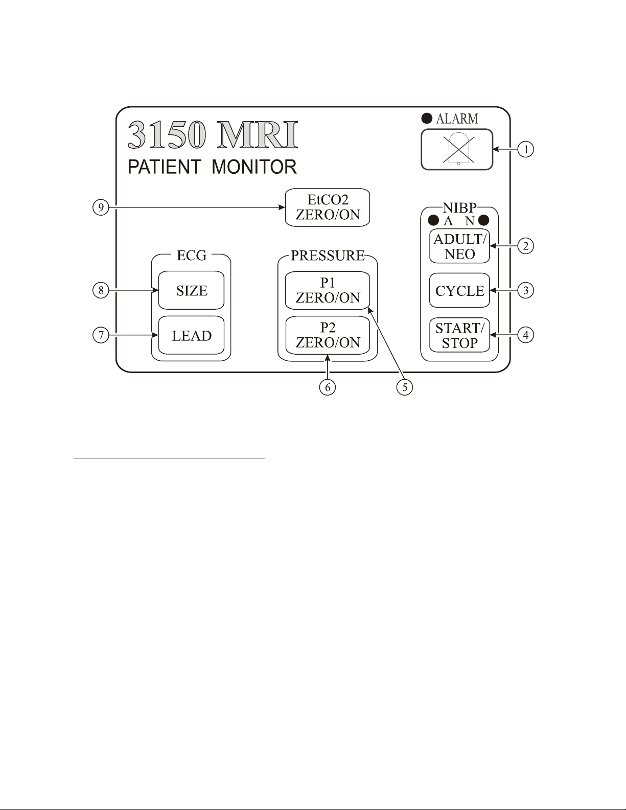
2.2 Front Panel Control Verification. (See Figure 2-1) Perform the following procedure to
verify the proper operation of the Control Keys on the 3150/3150M monitor Control Panel.
Figure 2-1. The 3150/3150M Monitor Control Panel
2.2.1 ECG Control Keys Verification. Perform the following procedure to verify proper operation
of the ECG Control Keys:
a. ECG LEAD Control Key. (Item 7) Perform the following procedure to verify proper
operation of the ECG LEAD Control Key:
(1) Note the Lead displayed on the Display Screen then press the ECG LEAD Control
Key.
(2) Observe that the displayed Lead (noted above) changed.
(3) Continue to press the ECG LEAD Control Key to verify that ECG Leads I, II
(default), III, AVL, AVF, AVR and CAL (available in Stand Alone Mode only)
may be selected.
(4) Press the ECG LEAD Control Key until ECG Lead II is displayed on the Display
Screen.
b. ECG SIZE Control Key. (Item 8) Perform the following procedure to verify proper
operation of the ECG SIZE Control Key:
(1) Note the Lead Size displayed on the Display Screen then press the ECG SIZE
Control Key.
(2) Observe that the displayed Size (noted above) changed.
(3) Continue to press the ECG SIZE Control Key to verify that the following Sizes
may be selected: 5, 10, 15, 20, 25, 30, 40 and A.
(4) Press the ECG SIZE Control Key until A is displayed on the Display Screen.
2-2
 Loading...