

Invivo RM9311N12, DR3160BAS Users Manual


Invivo Corporation
3160 MRI PHYSIOLOGICAL MONITORING SYSTEM
OPERATIONS MANUAL


TABLE OF CONTENTS
Paragraph Number Page Number
List of Figures ...........................................................................................................................................iv
List of Tables..............................................................................................................................................v
Equipment Classification ........................................................................................................................ v
Precautions ................................................................................................................................................vi
User Responsibility ................................................................................................................................xiv
3160 MRI Physiological Monitor Accessories.................................................................................. xv
1.0 INTRODUCTION ......................................................................................................... 1-1
1.1 Product Description ......................................................................................................... 1-1
1.1.1 System Mounting................................................................................................. 1-1
1.1.2 System Parameters............................................................................................... 1-1
1.1.3 User Interface....................................................................................................... 1-2
1.1.4 Versatility............................................................................................................. 1-2
1.2 Wireless Processor Unit (WPU) ...................................................................................... 1-2
1.2.1 Operating Environment........................................................................................ 1-2
1.2.2 Power Supply....................................................................................................... 1-2
1.2.3 Battery Operation................................................................................................. 1-2
1.3 Patient Connections ......................................................................................................... 1-2
1.3.1 NIBP and Agent Monitoring................................................................................ 1-2
1.3.2 ECG Monitoring .................................................................................................. 1-3
1.3.3 SpO2 Monitoring ................................................................................................. 1-3
1.4 Display Control Unit (DCU)............................................................................................ 1-3
1.4.1 DCU Controls ...................................................................................................... 1-3
1.4.2 DCU Display........................................................................................................ 1-8
1.5 Cleaning ......................................................................................................................... 1-12
1.5.1 Cleaning Accessories......................................................................................... 1-12
2.0 INSTALLATION........................................................................................................... 2-1
2.1 Introduction...................................................................................................................... 2-1
2.2 Monitor Installation ......................................................................................................... 2-1
2.2.1 Monitor Mounting................................................................................................ 2-1
2.2.2 Preparing the 3160 MRI Physiological Monitoring System for Use................... 2-1
2.2.3 Monitor Start Up.................................................................................................. 2-1
3.0 PREPARATION FOR USE.......................................................................................... 3-1
3.1 Introduction...................................................................................................................... 3-1
3.2 SETUPS Menu................................................................................................................. 3-1
3.3 Store/Recall Setups ........................................................................................................ 3-20
3.4 Monitor Initialization..................................................................................................... 3-21
3.4.1 Default Initialization .......................................................................................... 3-21
3.4.2 Pre-Configured Initialization ............................................................................. 3-21
4.0 PATIENT PARAMETERS........................................................................................... 4-1
4.1 ECG Monitoring .............................................................................................................. 4-1
4.1.1 Patient and Lead Preparation ............................................................................... 4-1
4.1.2 Associated Waveforms and Displays .................................................................. 4-2
4.1.3 The ECG Menu.................................................................................................... 4-2
4.1.4 Alarm Limits........................................................................................................ 4-5
4.1.5 Trended Data........................................................................................................ 4-5
4.1.6 ECG Messages..................................................................................................... 4-5
i

TABLE OF CONTENTS
Paragraph Number Page Number
4.2 Non-Invasive Blood Pressure (NIBP) Monitoring .......................................................... 4-5
4.2.1 Theory of Oscillometric Measurement ................................................................ 4-6
4.2.2 Patient and Cuff Preparation................................................................................ 4-7
4.2.3 Associated Displays............................................................................................. 4-7
4.2.4 The NIBP Menu................................................................................................... 4-9
4.2.5 NIBP Menu Options ............................................................................................ 4-9
4.2.6 Using the Automatic Interval Mode .................................................................. 4-11
4.2.7 Manually Starting/Stopping a Reading Cycle ................................................... 4-11
4.2.8 Stat Mode Operation.......................................................................................... 4-11
4.2.9 Alarm Limits...................................................................................................... 4-11
4.2.10 Adult vs. Neonatal Mode Operation .................................................................. 4-11
4.2.11 Trended Data...................................................................................................... 4-11
4.2.12 NIBP Messages.................................................................................................. 4-12
4.3 SpO2 Monitoring ........................................................................................................... 4-12
4.3.1 Sensor Positioning ............................................................................................. 4-12
4.3.2 Associated Waveforms and Displays ................................................................ 4-13
4.3.3 SpO2 Menu ........................................................................................................ 4-13
4.3.4 Alarm Limits...................................................................................................... 4-14
4.3.5 Trended Data...................................................................................................... 4-14
4.3.6 SpO2 Messages.................................................................................................. 4-14
4.4 End-tidal CO2 (EtCO2) Monitoring .............................................................................. 4-15
4.4.1 Patient and Sampling Line Preparation ............................................................. 4-15
4.4.2 Water Trap Replacement ................................................................................... 4-17
4.4.3 Associated Waveforms and Displays ................................................................ 4-17
4.4.4 EtCO2 Menu ...................................................................................................... 4-18
4.4.5 Calibration of CO2/N2O Measurement System ................................................ 4-18
4.4.6 Alarm Limits...................................................................................................... 4-19
4.4.7 Trended Data...................................................................................................... 4-19
4.4.8 EtCO2 Messages................................................................................................ 4-19
4.5 Anesthetic Agent/Oxygen Monitoring........................................................................... 4-20
4.5.1 Patient and Tubing Preparation.......................................................................... 4-20
4.5.2 Associated Displays........................................................................................... 4-21
4.5.3 Agent Menu ....................................................................................................... 4-23
4.5.4 Gas Calibration .................................................................................................. 4-23
4.5.5 Alarm Limits...................................................................................................... 4-24
4.5.6 Trended Data...................................................................................................... 4-24
4.5.7 Agent/O2 Messages ........................................................................................... 4-24
4.5.8 Oxygen Monitoring............................................................................................ 4-25
5.0 RECORDING AND TRENDING ................................................................................ 5-1
5.1 Introduction...................................................................................................................... 5-1
5.1.1 Record Key .......................................................................................................... 5-1
5.2 The RECORDER Menu................................................................................................... 5-1
ii

TABLE OF CONTENTS
Paragraph Number Page Number
5.3 Recording Charts ............................................................................................................. 5-3
5.3.1 Strip Chart Record ............................................................................................... 5-4
5.3.2 Tabular Chart Record........................................................................................... 5-4
5.3.3 Trend Chart .......................................................................................................... 5-5
5.3.4 System Data Report ............................................................................................. 5-5
5.4 Loading Recorder Paper .................................................................................................. 5-5
5.5 Trending Feature.............................................................................................................. 5-5
5.5.1 HISTORY Menu Options .................................................................................... 5-6
6.0 ALARMS ........................................................................................................................ 6-1
6.1 Introduction...................................................................................................................... 6-1
6.2 Alarm Limits.................................................................................................................... 6-1
6.2.1 Default (Pre-Set) Alarm Limits ........................................................................... 6-1
6.2.2 Range of High and Low Alarm Limits ................................................................ 6-1
6.3 Alarm Setup ..................................................................................................................... 6-1
6.3.1 Parameter Alarms Status Screen.......................................................................... 6-4
6.4 Turning Alarms Off on Individual Parameters ................................................................ 6-4
6.5 Alarm Violations.............................................................................................................. 6-4
6.6 Adjusting the Alarm Tone Volume ................................................................................. 6-5
6.6.1 Disabling the Alarm Tone.................................................................................... 6-5
6.7 Standby Mode .................................................................................................................. 6-6
7.0 BATTERY OPERATION............................................................................................. 7-1
7.1 Introduction...................................................................................................................... 7-1
7.2 Battery Location and Access ........................................................................................... 7-1
7.3 Loading and Unloading Battery(s) .................................................................................. 7-1
7.4 Battery Charging.............................................................................................................. 7-1
7.5 Battery Operation Time ................................................................................................... 7-1
7.5.1 Battery Low Indication ........................................................................................ 7-1
7.6 Battery Replacement........................................................................................................ 7-1
Specifications............................................................................................................................. A-1
Repair..........................................................................................................................................B-1
Warranty ....................................................................................................................................C-1
Declaration of Conformity ....................................................................................................... D-1
kPa to mmHg Conversion Chart .............................................................................................. E-1
List of Symbols ........................................................................................................................... F-1
iii

LIST OF FIGURES
Figure Number Page Number
1-1 Patient Connection Unit (PCU) ....................................................................................... 1-2
1-2 The Front Panel................................................................................................................ 1-3
1-3 The Top Keypad Set ........................................................................................................ 1-4
1-4 The Middle Keypad Set ................................................................................................... 1-5
1-5 The Bottom Keypad Set................................................................................................... 1-6
1-6 The Normal Screen .......................................................................................................... 1-8
1-7 The Informational Display............................................................................................... 1-8
1-8 The Vital Signs Trace Display......................................................................................... 1-9
1-9 The Vital Signs Numeric Display.................................................................................. 1-10
3-1 The DCU SETUPS Menu ................................................................................................ 3-1
3-2 The RECALL SETUPS Menu......................................................................................... 3-2
3-3 The STORE SETUPS Menu............................................................................................ 3-3
3-4 The PARAMETER SELECTION Menu......................................................................... 3-4
3-5 The SOUND ADJUST Menu .......................................................................................... 3-5
3-6 The SET TIME Menu ...................................................................................................... 3-7
3-7 NETWORK Menu ........................................................................................................... 3-8
3-8 The DCU SERVICE (BIO-MED) Menu ......................................................................... 3-8
3-9 The SYSTEM CONFIG Menu ........................................................................................ 3-9
3-10 WPU SETUPS Menu..................................................................................................... 3-11
3-11 The PARAMETER SELECTION Menu....................................................................... 3-11
3-12 The SOUND ADJUST Menu ........................................................................................ 3-13
3-13 The SET TIME Menu .................................................................................................... 3-14
3-14 The WPU SERVICE (BIO-MED) Menu....................................................................... 3-15
3-15 NIBP TESTS Menu ....................................................................................................... 3-16
3-16 GAS CAL Menu ............................................................................................................ 3-17
3-17 Monitor Calibration YES/NO Menu.............................................................................. 3-18
3-18 Monitor Calibration Information Screen ....................................................................... 3-18
3-19 System Configuration Menu.......................................................................................... 3-19
4-1 ECG Trace and Numerical Displays................................................................................ 4-1
4-2 The ECG Menu................................................................................................................ 4-2
4-3 The ECG SCALE Sub-Menu........................................................................................... 4-3
4-4 The ECG HR SOURCE Sub-Menu ................................................................................. 4-4
4-5 Oscillometric Measurement Method ............................................................................... 4-6
4-6 The NIBP Display............................................................................................................ 4-7
4-7 The NIBP Menu............................................................................................................... 4-8
4-8 The NIBP INTERVAL Menu.......................................................................................... 4-9
4-9 The HISTORY Menu..................................................................................................... 4-10
4-10 SpO2 Display................................................................................................................. 4-13
4-11 The SpO2 Menu............................................................................................................. 4-13
4-12 The SpO2 SIZE Menu ................................................................................................... 4-14
4-13 The Patient Sampling Circuit......................................................................................... 4-16
4-14 Water Trap Installation Diagram ................................................................................... 4-16
4-15 The EtCO2 Display........................................................................................................ 4-17
4-16 The EtCO2 Menu........................................................................................................... 4-18
4-17 Anesthetic Agents Display............................................................................................. 4-20
5-1 The RECORDER Menu................................................................................................... 5-2
iv

LIST OF FIGURES
Figure Number Page Number
5-2 Sample Strip Chart........................................................................................................... 5-4
5-3 Sample Tabular Chart ...................................................................................................... 5-4
5-4 System Data Report ......................................................................................................... 5-5
5-5 Loading the Recorder Paper ............................................................................................ 5-5
5-6 The HISTORY Menu....................................................................................................... 5-6
5-7 The MULTI TRENDS Menu........................................................................................... 5-7
5-8 The Trend SELECT Menu............................................................................................... 5-7
5-9 Sample Multi Trends Printout.......................................................................................... 5-8
6-1 The ALARMS Menu ....................................................................................................... 6-1
6-2 GAS ALARMS (Anesthetic Agents Alarm Limit) Menu ............................................... 6-3
LIST OF TABLES
Table Number Page Number
4-1 Agent Display During Mixed Agent Conditions ........................................................... 4-22
4-2 Agent Display During Mixed Agent Conditions .......................................................... 4-23
6-1 Alarm Limit Factory Default Settings ............................................................................. 6-7
6-2 Range of Alarm Limits .................................................................................................... 6-8
EQUIPMENT CLASSIFICATION
Classification according to IEC-60601-1
According to the type of protection against
electrical shock:
According to the degree of protection against
electrical shock:
According to the degree of protection against
harmful ingress of water:
According to the methods of sterilization or
disinfection:
According to the mode of operation: Continuous operation.
Equipment not suitable for use in the presence of flammable anesthetic mixture with air or with
oxygen or nitrous oxide.
Class I equipment.
Type CF (defibrillator-proof) equipment.
Ordinary equipment (enclosed equipment
without protection against ingress of water).
Non-sterilizable. Use of liquid surface
disinfectants only.
v

Precautions
General
Federal law in the USA or Canada restricts this device to sale by, or on, the order of a physician.
The accuracy of the measurements can be affected by the position of the patient, the patient’s
physiological condition, and other factors. Always consult a physician for interpretation of
measurements made by this monitor.
To avoid monitor fall, secure monitor on the shelf or bracket prior to use.
An explosion hazard exists if this monitor is used in the presence of flammable anesthetics.
The operator should read and thoroughly understand this manual completely before attempting to
operate the 3160 MRI Physiological Monitoring System.
If any system failure occurs (e.g. an unexplained continuous audible alarm) remove the monitor
from use, and refer it to qualified service personnel.
When an “X” appears in the Alarm Bell symbol, the audible alarm tone will not sound for any
reason.
Perform operational checkout before each use. If monitor fails to function properly, refer to
qualified service personnel.
For safe and accurate operation, use only recommended Invivo patient cable, lead wires, cuffs,
hoses, sensors, tubing, etc. A listing of these can be found in the Accessory Listing within this
manual, or by contacting Invivo directly.
For continued operation, always connect the monitor to AC Main Power when a Low Battery
indication occurs. Failure to do this can lead to interruption of monitoring and/or damage to the
monitor’s battery(s).
The system may not conform to all performance specifications if stored or used outside the
environmental specifications identified in Appendix A in the rear of this manual.
Do not apply any unnecessary pressure to the screen area of the monitor. Severe pressure applied
to this portion of the monitor could result in damage or failure of this screen.
All equipment not complying with IEC 60601-1 should be placed outside the patient
environment. Only connect IEC 60601-1 compliant equipment to this monitor. To avoid
potentially hazardous leakage currents, always check the summation of leakage currents when
several items of equipment are interconnected.
For proper equipment maintenance, perform the service procedures at the recommended intervals
as described in the monitor’s service manual.
Single use devices should never be reused.
Organic vapors (e.g. from cleaning agents) in sampling line or room air may alter anesthetic agent
readings.
Alcohol in patient's breath may modify the anesthetic agent readings.
vi

Precautions
Electrical Safety
To avoid an electrical hazard, never immerse the unit in any fluid or attempt to clean it with liquid
cleaning agents. Always disconnect monitor from AC Main Power before performing cleaning or
maintenance.
If monitor becomes accidentally wet during use, discontinue operation of the monitor until all
affected components have been cleaned and permitted to dry completely. Contact your local
Invivo representative if additional information is required.
Shock hazard exists if operated without chassis cover. Refer servicing to qualified service
personnel only.
For continued protection against fire hazard, replace fuses with same type and rating only.
Connect the monitor only to a three-wire, grounded, hospital-grade receptacle. The three-
conductor plug must be inserted into a properly wired three-wire receptacle; if a three-wire
receptacle is not available, a qualified electrician must install one in accordance with the
governing electrical code.
Do not under any circumstances remove the grounding conductor from the power plug.
Avoid use of electrical power extension cords. Electrical power extension cords may create a
safety hazard by compromising the grounding integrity of the monitor.
None of the monitor interconnection ports on the rear of the monitor (e.g. Communication Ports,
Auxiliary Input/Output port [AUX I/O], ECG Sync Input [ECG SYNC IN], Keyboard or Video
Input) are intended for direct patient connection. An electric shock hazard can exist if the patient
is electrically connected to any of these connections.
This monitor and its listed accessories may be safely powered by the voltages 110-120/220-240
VAC having a frequency of 50 or 60 Hz.
If the integrity of the earth ground conductor of the AC mains power cable is in doubt, operate the
monitor on internal battery power until proper earth ground connection is confirmed.
Patient Safety
Constant attention by a qualified individual is needed whenever a patient is under anesthesia or
connected to a ventilator. Some equipment malfunctions may occur in spite of equipment or
monitor alarms.
Always test sampling line adapter for a tight connection and proper operation before attaching to
a patient.
As with all medical equipment, carefully route patient cabling to reduce the possibility of patient
entanglement or strangulation.
Occupational Safety
Connect the sample gas outlet on the monitor's rear panel to a scavenging system to prevent
pollution of room air.
Handle the Patient Sampling Line and its contents as you would any body fluid. Infectious hazard
may be present.
MRI Use Precautions
Certain components of this device will be affected by the magnetic and radio frequency fields present
in your MRI System. Confer with your MRI physicist and/or Radiology staff to identify the proper
placement and use areas for the monitor and its accessories, as defined on the monitor or accessory
labeling. Failure to properly place the monitor and its accessories in the Magnet Room will result in
monitor failure, and possible patient or user injury. Always position the 3160 MRI Physiological
Monitoring System at, or outside, the 5000 Gauss (0.5T) field line of the MRI system. A slight
distortion of the MRI magnetic field homogeneity or possible damage to either the monitor's NIBP or
EtCO2 pump could occur.
vii

Precautions
MRI Use Precautions (Continued)
Always verify proper communicationof the 3160 MRI Physiological Monitoring System with
the Remote Monitor prior to patient use.
MRI Magnet Room Placement. The 3160 MRI Physiological Monitoring System is designed to be
used in conjunction with a remote monitor. The 3160 MRI Physiological Monitoring System is
specially designed not to interfere with MRI operations and may be used inside the MRI Magnet Room
in any location at or outside the 5000 Gauss (0.5T) Field Line of the MRI System. If brought closer
than the 5000 Gauss Field Line, the NIBP monitor pump and EtCO2 pump may fail to operate.
The Remote Monitor is also specifically designed not to interfere with MRI operations, and may be
used in the Magnet Room at or outside the 1000 Gauss (0.1T) Field Line of the MRI System. If
brought closer than the 1000 Gauss Field Line, monitor damage (failure to operate) may result.
Risk of RF current burn. Cables which become inadvertently looped during MRI act as conductive
lines for RF induced currents. When lead wires or other cables form a conductive loop in contact with
the patient's tissue, minor to severe burning can result.
Perform the following to minimize risk of RF current burn:
a. Place cables and lead wires neatly in straight alignment with no looping.
b. Keep the length of lead wires and patient cable within the bore to a minimum.
c. RF burn risk increases when multiple sensors/cables are in use. Such combinations are
not recommended.
d. The high radio frequency (RF) power used in MRI scanning poses an ever-present risk
of excessive heat at the monitoring sites and, therefore, the risk of RF current burn.
Should power levels greater than S.A.R. of 4 w/kg peak (0.4 w/kg average) be
used, the risk of patient burn greatly increases. As a result, monitoring of ECG at
power levels of greater than 4 w/kg peak (0.4 w/kg average) is not recommended for
the general patient population. Such monitoring should only be attempted on conscious
patients with good temperature reflex so they may warn the operator of excessive heat
at the monitoring sites.
e. High RF Power may cause patient heating or burns. For scans with average S.A.R. > 1
w/kg, limit scan time to 5 minutes and pause at least 3 minutes between scans to allow
ECG Cable to cool.
MRI Compatibility
The Quadtrode® MRI ECG Electrode Pad, and ECG Patient Lead Wires and Cable, are compatible
with Magnetic Resonance Imaging (MRI) Systems within the following guidelines:
• MRI systems with static magnetic field strengths up to 1.5 Tesla.
• Usable within the MRI system bore with Specific Absorption Ratios (S.A.R.'s) up to 4.0 w/kg
(peak). Use with higher S.A.R.'s greatly increases the risk of patient burns.
• Non-Magnetic materials are used in the construction of these assemblies.
• If scanned directly across the plane of the ECG electrode element, a slight image distortion may
be seen at the skin surface where the electrode element is positioned.
viii

Precautions
ECG
An inoperative ECG monitor is indicated by absence of an ECG waveform and a simultaneous
Lead Fail alarm.
For best ECG, Heart Rate, S-T Segment, and/or Respiration monitoring, always select the
optimum lead configuration which has the least artifact and largest waveform(s) being detected
for monitoring use.
Failure to respond to a Lead Fail alarm will cause a lapse in your patient’s monitoring. Always
respond promptly to this and any other alarms.
Heart rate values may be adversely affected by cardiac arrhythmia, or by operation of electrical
stimulators.
NIBP
Always use recommended NIBP cuffs and hoses. Avoid compression or restriction of NIBP cuff
hose.
When using the NIBP portion of this instrument to measure blood pressure, remember that the
patient’s blood pressure readings are not continuous, but are updated each time a blood pressure
measurement is taken. Set a shorter interval for more frequent updating of the patient’s blood
pressure.
Do not attach the cuff to a limb being used for infusion. Cuff inflation can block infusion, possibly
causing harm to the patient.
Frequent NIBP measurements can cause pooling of the blood in the limb (hemostasis), and
peripheral tissue/nerve damage. Allow sufficient time between measurements for blood
recirculation to prevent pooling of the blood in the limb.
Arrhythmic and/or erratic heart beats (or severe motion artifact, such as tremors or convulsions)
can result in inaccurate readings and/or prolonged measurements. If questionable readings are
obtained, re-check patient’s vital signs by alternate means before administering medication.
To prevent possible nerve damage to the limb, apply the NIBP cuff as recommended by current
American Heart Association (AHA) guidelines for blood pressure monitoring.
To ensure accurate and reliable measurements, use only recommended patient cuffs/hoses. For
best accuracy, use the appropriate cuff size for each patient as recommended by the current AHA
guidelines for blood pressure monitoring.
Always tighten the cuff air hose connections snugly into place for proper operation.
Some reusable NIBP cuffs contain a medical-grade latex rubber. Patients sensitized to latex
rubber can have an allergic reaction when exposed to this material. Avoid the use of cuffs which
contain latex rubber on patients who are allergic to this material.
Routinely inspect the cuff and hose assemblies for proper attachment and orientation. Replace
cuff and/or hose assemblies with cracks, holes, tears, cuts, etc. that could cause leaks in the
system. If cuff and/or hose assemblies with damage which could result in leaks are used,
prolonged and/or inaccurate patient readings could result.
To prevent skin abrasion, apply and remove cuff carefully. Keep Velcro® (hook and latch)
retention areas away from the skin.
ix

Precautions
SpO2
Avoid placement of the SpO2 sensor on the same limb with an inflated blood pressure cuff. Cuff
inflation could result in inaccurate readings and false alarm violations.
SpO2 monitoring requires the detection of valid pulses to correctly determine SpO2 and Heart
Rate values. During conditions of gross artifact, or in the absence of valid pulses, the SpO2 /rate
values may not be correct.
The SpO2 monitoring portion of this monitor is intended to measure arterial hemoglobin oxygen
saturation of functional hemoglobin (saturation of hemoglobin functionally available for
transporting oxygen in the arteries). Significant levels of dysfunctional hemoglobins, such as
carboxyhemoglobin or methemoglobin, may affect the accuracy of the measurement. Also,
Cardiogreen and other intravascular dyes may, depending on their concentration, affect the
accuracy of the SpO2 measurement.
Always shield the SpO2 sensor from extraneous incident light sources. Such extraneous light can
cause SpO2 reading or pulse detection errors.
Frequently inspect the SpO2 sensor site for possible pressure tissue necrosis during prolonged
monitoring. Reposition the sensor at least every four (4) hours. Special care should be exercised
when tape is used to secure the sensor, as the stretch memory properties of most tapes can easily
apply unintended pressure to the sensor site.
The numeric measurement values are updated every one (1) second on the monitor display.
A pulse oximeter should be considered an early warning device. As a trend towards patient
deoxygenation is indicated, blood samples should be analyzed by a laboratory co-oximeter to
completely understand the patient’s condition.
The pulse oximeter feature in this monitor is designed to display functional SpO2 values.
The pulse oximeter pulsatile waveform is not proportional to the pulse volume, but adjusts the
waveform amplitude as needed for proper viewing.
All monitor alarms are categorized as medium priority, unless otherwise specified.
Arrhythmic and/or erratic heart beats (or severe motion artifact, such as tremors or convulsions)
can result in inaccurate readings and/or prolonged measurements. If questionable readings are
obtained, re-check patient’s vital signs by alternate means before administering medication.
Respiration
When setting up respiration monitoring, always observe and adjust the respiration gain of the
monitor while watching the patient’s breathing efforts before completing selection of the gain
setting. Failure to do this can result in inaccurate readings, or false respiration detection.
End-tidal CO2 (EtCO2)
Verify that the patient’s breathing efforts and timing coincide with the monitor’s waveform before
completion of the patient set-up.
The EtCO2/N2O measurements are automatically pressure compensated over an ambient pressure
range from 576 to 788 mmHg.
The EtCO2/N2O measurement displays the sampled value within 1 second of when the gas was
sampled.
The alarm tone volume exceeds 60 dBA at a distance of 1 meter when the alarm tone volume
adjustment is set above selection number 8.
Frequently inspect the EtCO2 patient tubing for proper gas flow. Avoid kinking of the EtCO2
patient tubing that can result in leaking, reduction, or cut-off of the sample gas flow. Inaccurate gas
measurements could result.
x

Precautions
End-Tidal CO2 (Continued)
EtCO2 patient tubing and its associated components are intended for single-patient use only.
Avoid cleaning or disinfecting these items for reuse. Inaccurate gas measurements could result.
To prevent inaccurate or missed readings, keep the EtCO2 patient tubing clear of any moving
mechanisms which may kink, cut or dislodge the patient tubing.
Do not overtighten the patient gas sample line to the water trap connector. Overtightening this
connector can cause failure of the water trap assembly and resultant inaccurate (artificially low)
patient gas measurements.
Avoid connecting the EtCO2 calibration gas canister to the monitor by any method other than
with the designated calibration tubing. Connecting by any other method could invalidate the
calibration, and/or damage the monitor.
Respiration rate measurement errors could result during ventilation rates above 80 breaths per
minute.
Anesthetic Agents
Inadequate ventilation of the monitor may cause inaccurate readings or damage to electronic
components.
Ensure that the exhaust gas is not removed from the monitor under too strong a vacuum. To
prevent this condition, there must always be an opening to the room air. Too high a vacuum level
may change the operating pressure of the monitor and cause inaccurate readings or internal
damage.
Inspect waste gas line for deterioration on a regular basis. Replace as needed.
Remove sampling line from patient airway whenever nebulized medications are being delivered.
Use only Invivo sampling lines and accessories; other sampling lines may cause inaccurate
readings and malfunctions.
Some Hydrocarbons (e.g. Acetone, Methane) may cause a mixed agent alarm to occur.
Replace the sampling line and inspect water trap between each patient use.
Do not overtighten the patient gas sample line to the water trap connector. Overtightening this
connector can cause failure of the water trap assembly and resultant inaccurate (artificially low)
patient gas measurements.
Routinely inspect the hose assemblies for proper attachment and orientation. Replace hose
assemblies with cracks, holes, tears, cuts, etc. that could cause leaks in the system. If hose
assemblies with damage which could result in leaks are used, prolonged and/or inaccurate patient
readings could result.
If questionable anesthetic agent gas measurements are observed, recheck patient connections,
anesthesia gas machine and/or vaporizer before re-adjusting anesthesia delivery.
Routinely verify the monitor’s internal barometric pressure reading with local conditions during
the initial start-up period.
xi

Precautions
Anesthetic Agents (Continued)
With no gas reading (Agent Icon box with white X for agent identification and agent values of “--
-”) when Agent Vaporizer is first turned on, it may take 30 seconds to 1.5 minutes for agent
identification and reading to be displayed. Once identification is established, changes in
concentration are virtually immediate. With a 200% change in concentration, an auto Zero will
occur, and full accuracy of the changed concentration will be accomplished within approximately
30 seconds.
Whenever the 3160 MRI Physiological Monitoring System Agent sensor changes from steady state
condition, the 3160 MRI Physiological Monitoring System will perform an auto zero to restabilize
the sensor readings. During this time, 15 seconds to 1.5 minutes, it is possible for a false
identification and concentration value to occur. Examples are as follows:
a. No gas, during warm-up and when sample line is disconnected.
b. Applying sample line for the first time.
c. When switching from one Agent to another.
d. Applying N2O in concentrations of 70% or more.
e. Going from N2O of greater than 50% to 0%.
f. When going from high Agent concentrations to low or off.
Other
This product, or any of its parts, should not be repaired other than in accordance with written
instructions provided by Invivo, or altered without prior written approval of Invivo Corporation.
The user of this product shall have the sole responsibility for any malfunction which results from
improper use, faulty maintenance, improper repair, damage, or alteration by anyone other than
Invivo, or its authorized service personnel.
This monitor is equipped with a demonstration mode which displays simulated electronic patient
data for training or demonstration purposes. Do not attach a patient to the monitor whenever this
simulation is present on the monitor display (“SIMULATION” can also be seen in the screen
center). Failure to properly monitor the patient could result.
The patient connector inputs for all parameters are protected against the use of a defibrillator by
internal circuitry, and when the recommended patient cables or accessories are used. The use of
this circuitry and these recommended cables and accessories also protects against the hazards
resulting from use of high frequency surgical equipment.
There are no known electromagnetic or other hazardous interference between the monitor and
other devices. However, care should be taken to avoid the use of cellular phones or other
unintended radio-frequency transmitters in the proximity of the monitoring system.
This monitor uses rechargeable batteries which contain hazardous material, which must be
recycled, or disposed of properly. For proper disposal methods, contact your local Invivo
representative or distributor.
Avoid ammonia, phenol or acetone based cleaners for they may damage the monitor surface.
Dispose of the monitor and parts thereof according to local regulations.
xii

Precautions
Other (Continued)
Notes, Cautions and Warnings. In the body of the manual notes, cautions and warnings are as
shown below to make them stand out on the page. The following is a description of the format and
meaning of Notes, Cautions and Warnings:
a. Notes. Notes are presented as shown below. Notes contain supplemental information
which Invivo has deemed especially important.
NOTE
This is a sample note.
b. Cautions. Cautions are presented as shown below. Cautions are used for the words
and/or terms which alert the user to the possibility of a problem with the device
associated with its use or misuse. Such problems may include device malfunctions,
device failure, damage to the device or damage to other property.
CAUTION
This is a sample caution.
c. Warnings. Warnings are presented as shown below. Warnings are used for the words
and/or terms which alert the user to possible injury, death or other serious adverse
reactions associated with the use or misuse of the device.
WARNING
This is a sample warning.
xiii

USER RESPONSIBILITY
This product will perform in conformity with the description contained in this operators manual
and accompanying labels and/or inserts, when assembled, operated, maintained and repaired in
accordance with the instructions provided. This product must be checked and calibrated
periodically. A malfunctioning product should not be used. Parts that are broken, missing, plainly
worn, distorted or contaminated should be replaced immediately. Should such repair or
replacement become necessary refer unit to qualified service personnel. This product or any of its
parts should not be repaired other than in accordance with written instructions provided by the
manufacturer, or altered without written approval of Invivo. The user of the product shall have the
sole responsibility for any malfunction which results from improper use, faulty maintenance,
improper repair, damage or alteration by anyone other than Invivo or Invivo authorized service
personnel.
Using this Manual. Whenever the various options are discussed, “XXX” is used to indicate a
variable setting. It is required that every operator read this manual completely, including any
patient information in sections about monitoring features the operators monitor does not have,
before attempting to operate the 3160 MRI Physiological Monitoring System.
The figures contained in this manual show a fully equipped monitor. Therefore, figures within
this manual may depict monitoring features that your monitor may not contain. For information
on features and enhancements that are not contained on your monitor, contact Invivo at (407) 275-
3220.
Precautions (listed earlier in this section) cover of wide ranges of information crucial to the safe
monitoring of patients. It is required that every operator read the PRECAUTIONS completely,
including the Precautions associated with monitoring features that the operators monitor does not
have, before attempting to operate the 3160 MRI Physiological Monitoring System.
This device is covered under one or more of the following U.S. Patents: 5,482,036; 5,490,505;
5,632,272; 5,685,299; 5,758,644; 5,769,785; 6,002,952; 6,036,642; 6,067,462; 6,206,830;
6,157,850; 6,277,081 and international equivalents. U.S.A. and international patents pending.
Possession or purchase of this device does not convey any express or implied license to use the
device with replacement parts which would, alone, or in combination with this device, fall within
the scope of one or more of the patents relating to this device.
For further information or assistance with this product:
Invivo Corporation
407-275-3220 or 800-331-3220
xiv

3160 MRI Physiological Monitor Accessories
ECG
Item Description Part Number
Quadtrode
MRI ECG Patient Lead Wire Set.......................................................................................................... 9218
ECG/EEG Skin Prep Gel, 1 tube 4 ounce ............................................................................................9009
Reusable BP Cuffs and Hoses
Twin-Lumen Adult Air Hose (18 ft. length) .................................................................................... 9010M
Single-Lumen Neonatal NIBP Air Hose (18 ft. length) ............................................................... 9010NM
Infant MRI BP Cuff......................................................................................................................9050MNL
Pediatric MRI BP Cuff .................................................................................................................9060MNL
Adult Standard MRI BP Cuff.......................................................................................................9070MNL
Adult Large Arm MRI BP Cuff...................................................................................................9080MNL
Adult Thigh MRI BP Cuff ...........................................................................................................9090MNL
Neonatal NIBP Cuff, Disposable, Size A, Velcro........................................................................ AN01AV
Neonatal NIBP Cuff, Disposable, Size B, Velcro ........................................................................ AN02AV
Neonatal NIBP Cuff, Disposable, Size C, Velcro ........................................................................ AN03AV
®
MRI ECG Electrodes, 50/box .......................................................................................9303N
Non-Invasive Blood Pressure
Disposable BP Cuffs
End-Tidal CO2
EtCO2 Sampling Kit...........................................................................................................................9010D
Contains 20 foot co-extruded sampling tube polyethylene inner core with PVC jacket, Nafion®
tube, elbow adapter and 0.8 micron disk filter.
Adult EtCO2 Cannula ...........................................................................................................................9012
Pediatric EtCO2 Cannula ...................................................................................................................... 9013
SpO2
Spare Wireless Pulse Oximeter Module............................................................................................... 9311
SpO2 Grip Sensor............................................................................................................................... 9399B
xv


SECTION 1
INTRODUCTION
1.0 INTRODUCTION.
This manual describes a fully configured monitor, and may include features and/or options that
are not included in your monitor. For additional information, contact your local sales
representative, or Invivo Customer Service.
1.1 Product Description. The Model 3160 MRI Physiological Monitoring System is designed
to assist clinicians in monitoring patient vital signs in the midst of the dynamic and evolving Magnetic
Resonance environment. A combination of the latest wireless communication, radio frequency (RF)
shielding, digital signal processing (DSP), and adaptable mounting technologies address the challenges
associated with patient monitoring in the MRI area. Built on Invivo’s strong heritage in MRI patient
vital signs monitoring, the 3160 provides accurate, continuous, and reliable performance during all
phase of MRI applications.
The standard 3160 configuration consists of wireless electrocardiogram (ECG), wireless pulse
oximetry (SpO2), and non-invasive blood pressure (NIBP). Optional parameters include end-tidal
CO2 and anesthetic agents.
The 3160 system consists of the following components:
a. Wireless Processing Unit. The Wireless Processing Unit (WPU) houses the
circuitry and hardware for support of the standard and optional patient monitoring
parameters. The transceivers and antennas that support wireless communication
with the ECG and SpO2 modules as well as the Display Controller Unit are also
part of the WPU. The unit is powered by an AC – DC power adapter or two
removable batteries that are recharged by the same power adapter. The batteries
provide 8 hours of continuous operation.
b. Patient Connection Unit. The Patient Connection Unit (PCU) contains the
connectors that support all the non-wireless parameters (i.e. NIBP, EtCO2, etc.)
c. Display Controller Unit. The WPU communicates to the Display Controller Unit
(DCU) via a bi-directional 2.4 GHz communication link. The large color LCD
display, keypad, and recorder of the DCU form an easy-to-use user interface for
display, control, and documentation of the system patient monitoring parameters.
d. Wireless ECG Module. The Wireless ECG (WECG) module communicates two
leads of ECG simultaneously to the WPU. These two leads of ECG can be
displayed at the DCU and are output from the WPU unit for interface to the MRI
system cardiac gating input.
e. Wireless SpO2 Module. The Wireless SpO2 (WSpO2) communicates the SpO2
value and pulse waveform to the WPU. The information is available for display at
the DCU and is output from the WPU for interface to the MRI system pulse
peripheral gating input.
1.1.1 System Mounting. The Model 3160 MRI Physiological Monitoring System is built upon an
adaptable mounting platform where the system can be configured in a traditional pole mount
configuration or mounted directly onto the MRI table. The MRI table mount provides an effective
means of allowing the Model 3160 to travel along with the patient on the MRI table thus improving
throughput and efficiency.
1.1.2
simultaneous processing and display of up to five (5) parameters, three (3) waveforms and associated
numeric values from each different parameter. All the Patient Information is clearly displayed on a Flat
Panel Display Screen.
System Parameters. The 3160 MRI Physiological Monitor System Parameters allow
1-1
The 3160 MRI Physiological Monitoring System includes the following Vital Sign
Parameters:
• Single Lead ECG • Pulse Oximetry • NIBP
• EtCO2 • Respiration • Anesthetic Agents
1.1.3
time. On the Display Control Unit (DCU), there is a Rotary Knob (which detents from selection to
selection) that is used to access the parameter menu's, access the various setup features and finalize any
changes to the setup of the monitor. Frequently used menus (such as: Alarms, Trends and Recorder)
have a Control Key which, when pressed, will open the associated menu. On the Wireless Processor
Unit (WPU), the operator needs an external display and a keyboard to access the various features.
1.1.4 Versatility. With its diverse offering of vital sign parameters, the 3160 MRI Physiological
Monitoring System may be configured to meet the monitoring needs of a wide spectrum of patients
from Neonate to Adults. Every available parameter may be easily accessed and adjusted to the unique
needs, condition and situation of each patient.
1.2 Wireless Processor Unit (WPU). The WPU contains wireless transceivers, data acquisition
and processing circuitry that communicate with the wireless Display Control Unit (DCU), ECG
(WECG) module and SpO2 (WSpO2) module.
1.2.1 Operating Environment. The WPU is designed to operate at the 5,000 Gauss line in the
generated RF field of an MRI system measured from the center line of the bore.
1.2.2 Power Supply. The WPU Power Supply is designed to operate on the floor at least 10 feet
from a 1.5 Tesla unshielded MRI system (200 Gauss). When attached, the power supply charges the
WPU battery pack whether the WPU is operating or not.
1.2.3 Battery Operation. The WPU will operate at least eight (8) hours with EtCO2 and all optional
devices running with NIBP performing automatic readings at five (5) minute intervals.
User Interface. A simple to use interface has been developed to minimize operator learning
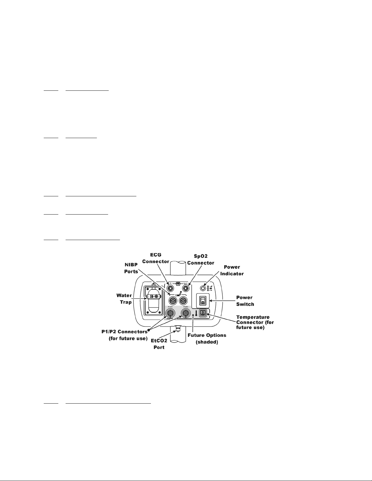
Figure 1-1. Patient Connection Unit (PCU)
1.3 Patient Connections. The physical patient connections for NIBP and the Anesthetic Agents
options are located on the Patient Connection Unit (PCU, See Figure 1-1). ECG, SpO2 and
Respiration all use wireless technology to deliver their measurements to the Wireless Processor Unit
(WPU).
1.3.1
Invasive Blood Pressure (NIBP) and, when installed, the optional Anesthetic Agents parameters. If
Anesthetic Agents is installed, the PCU also contains a water trap to prevent moisture contamination of
the agent components.
NIBP and Agent Monitoring. The PCU contains the physical connections for the Non-
a. Operating Environment. The PCU is designed to operate at the 5,000 Gauss line in
the generated RF field of an MRI system measured from the center line of the bore.
1-2

1.3.2
Wireless ECG Module consists of a wireless transceiver to communicate with the WPU and convert
the ECG signals into radio signals for transmission to the Wireless Processor Unit. The module also
receives information through the wireless link, converts the information to electrical signals and
performs the commanded task (i.e. lead configuration change, scaling, etc.).
1.3.3 SpO2 Monitoring. SpO2 is monitored using a SpO2 Telemetry Transmitter (WSpO2). The
Wireless SpO2 Module consists of a wireless transceiver to communicate with the Wireless Processor
Unit and convert the SpO2 pulse signal into radio signals for transmission to the Wireless Processor
Unit (WPU).
1.4 Display Control Unit (DCU). The DCU provides control and display of the monitored
parameters. Control of the Monitoring Features is provided through the use of a Rotary Knob; as the
operator turns the Rotary Knob (either clockwise or counterclockwise), with each detent the next
Menu-Select Icon (Vital Sign Numerical Display) will become highlighted (selected) and, when the
appropriate display is selected, pressing the Rotary Knob will bring up the menu for that parameter.
For control and adjustment of the operation and features, the Keypad contains three separate sets of
pushbutton keys which contain both operational and menu-select keys.
ECG Monitoring. ECG is monitored using an ECG Telemetry Transmitter (WECG). The
a. Compatability. The Standard Wireless ECG Module supports the four ECG electrode
placement used with the Quadtrode (Part # 9303), Quadtrode CV, Neonatal Quadtrode
and MRI ECG Patient Cable and Lead wires (Part # 9340) for display of Lead II.
b. Visual Indicators. The WECG module contains one (1) bi-color LED that indicates
the status of the battery charge.
c. Battery Life. The WECG module will operate at least eight (8) hours on a fully
charged battery.
a. Visual Indicators. The WSpO2 module contains one (1) bi-color LED that indicates
the status of the battery charge.
b. Battery Life. The WSpO2 module will operate at least eight (8) hours on a fully
charged battery
1.4.1 DCU Controls. (See Figure 1-2) The DCU front panel contains all the controls and access for
complete patient monitoring. Control is provided by the pushbutton keys and Rotary Knob. The
following is a general description of the DCU.
Figure 1-2. The Front Panel
1-3
a. The Rotary Knob. The Rotary Knob is located to the right of the Display Screen. The
function of the Rotary Knob is menu specific. For this reason, its various functions are
described throughout this document where it is used; in general, however, the Rotary
Knob operates as described below:
(1) As the Rotary Knob is rotated, either clockwise or counterclockwise, the
monitor display “scrolls” through the various screen items (screen icons, menu
options and patient parameters) which are available for selection. When the
appropriate item is “highlighted,” it may be selected by pressing and releasing
the Rotary Knob. All menus have a RETURN option which will return the
monitor to the previous menu selection.
(2) During normal operation each active parameter has a Menu-Select icon on the
screen. When the Rotary Knob is rotated, the Menu-Select icon which is being
pointed at becomes “highlighted.” Rotating the Rotary Knob will cause the
monitor to “scroll through” the available menu selections. Once the appropriate
Menu-Select icon is highlighted, pressing the Rotary Knob completes the
selection and brings up the required menu. Once the menu is selected, the
Rotary Knob is used to scroll through the available choices and make
adjustments to the selected parameter. The following Menu-Select Icons may
be available on the Normal Screen (depending on which parameters are
available, enabled and turned on): ECG, NIBP, SpO2, EtCO2 and Agents.
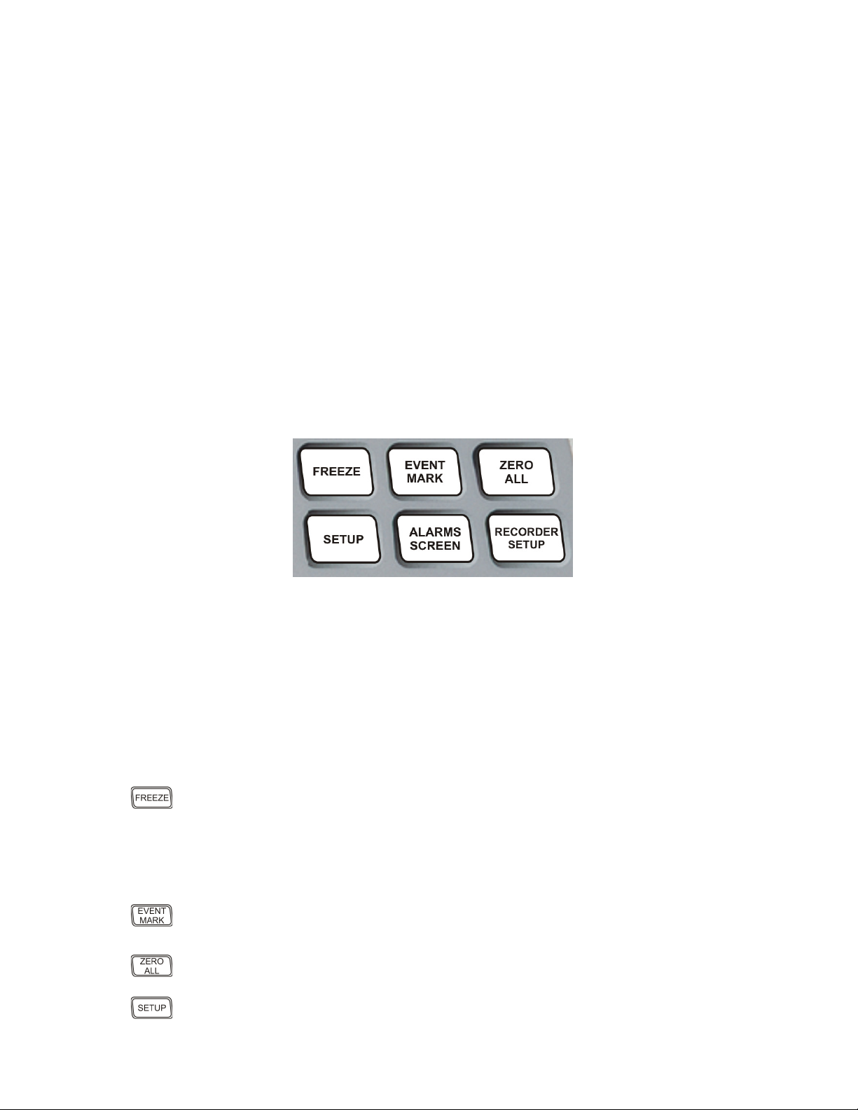
Figure 1-3. The Top Keypad Set
b. The Top Keypad Set. (See Figure 1-3) There are six push keys in the top keypad set.
The top three (FREEZE, EVENT MARK and ZERO ALL) provide direct control of
a monitor feature while the bottom three (SETUP, ALARMS SCREEN and
RECORDER SETUP) provide access to operational menus. The six push keys are
described below:
(1) FREEZE. The 3160 MRI Physiological Monitoring System freezes the
ECG waveform from Trace A for closer examination upon user demand.
When the ECG trace is active, pressing the FREEZE key will freeze it into the
Trace B location while Trace A remains active. When the trace is frozen,
pressing the FREEZE key will release it. A “Blue Box” appears around the
(2) EVENT MARK. The EVENT MARK key prints a marker on the ECG
(3) ZERO ALL. This feature is not available. Pressing this key will display a
frozen waveform as a visual indication that the waveform is not active. While
the Freeze feature is active, the monitor will not allow any changes to the
Parameter Setups or Display; if the operator attempts to access the
PARAMETER SELECTION menu, a WARNING Box alerts the operator
that entry to the selected menu is not allowed while FREEZE is enabled.
Recorder Strip when the printer is running. If the printer is not running,
pressing this key has no effect.
dialog box that alerts the operator that no Invasive Pressures are enabled.
(4) SETUP. The SETUP key allows the operator to access the various available
setup options.
1-4
(5) ALARMS SCREEN. The ALARMS SCREEN key is a dual function key
that allows the operator to setup the Alarms monitoring feature. When the
monitor display is in the Normal Screen and the ALARMS SCREEN key is
(6) RECORDER SETUP. The RECORDER SETUP key allows the operator
c. The Middle Keypad Set. (See Figure 1-4) The middle keypad set contains six push
keys. The three on the left provide control of the NIBP monitoring feature with two of
the keys (NIBP START/STOP and NIBP STAT) providing direct control of NIBP
measurements and the third (NIBP INTERVAL) bringing up a menu that allows
adjustment of the NIBP auto mode interval feature. On the right side of this set are two
keys which control the Trending feature of the monitor (TRENDS and CLEAR
TRENDS) while a third (RECORD) provides a hardcopy printout of selected
parameters as specified by operator adjustments in the RECORDER Menu. The six
push keys are described below:
pressed, the Main Alarm Setup Screen will appear; when the monitor display
has any icon highlighted and the ALARMS SCREEN key is pressed, an
Alarm Setup Screen for the highlighted parameter appears.
to setup the Recorder option.
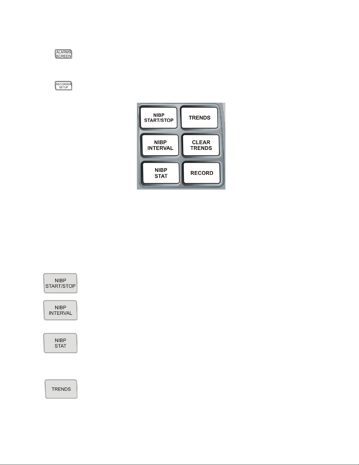
Figure 1-4. The Middle Keypad Set
(1) NIBP START/STOP. This key starts a new NIBP measurement, or stops a
(2) NIBP INTERVAL. Pressing the NIBP INTERVAL key brings up the NIBP
(3) NIBP STAT. This key starts the NIBP STAT Mode measurements. This
(4) TRENDS. The TRENDS key allows the operator to setup the Trend
measurement that is already in progress..
INTERVAL Menu where the cycle time (time between readings) of the NIBP
Automatic Reading Mode may be adjusted.
mode may be terminated by depressing the NIBP START/STOP key. The
STAT Mode performs up to five (5) NIBP measurements in rapid succession
(with a short pause between readings) within a maximum time frame of five
(5) minutes.
monitoring feature. The exact operation of the TRENDS key is based on
whether or not a feature is currently highlighted. If a feature is currently
highlighted, pressing the TRENDS key will bring up a Trend which is specific
to the highlighted feature; if a feature is not currently highlighted, pressing the
TRENDS key will bring up the HISTORY Menu and Tabular Display (See
Section 5).
1-5
(5) CLEAR TRENDS. Pressing the CLEAR TRENDS key allows the operator
to clear all the stored data from memory. To prevent accidental erasure of
(6) RECORD. Pressing this key records the Single Trace or Dual Trace selections
patient data, there is a Yes/No box associated with this key that appears to
ensure that the operator meant to clear the trend data.
(as specified by operator adjustments made in the RECORDER Menu).
The recorder stops automatically after approximately 30 seconds, or when the
RECORD key is pressed again; in either case, the printout ends with a “Snap
Shot” of the active patient parameter data.
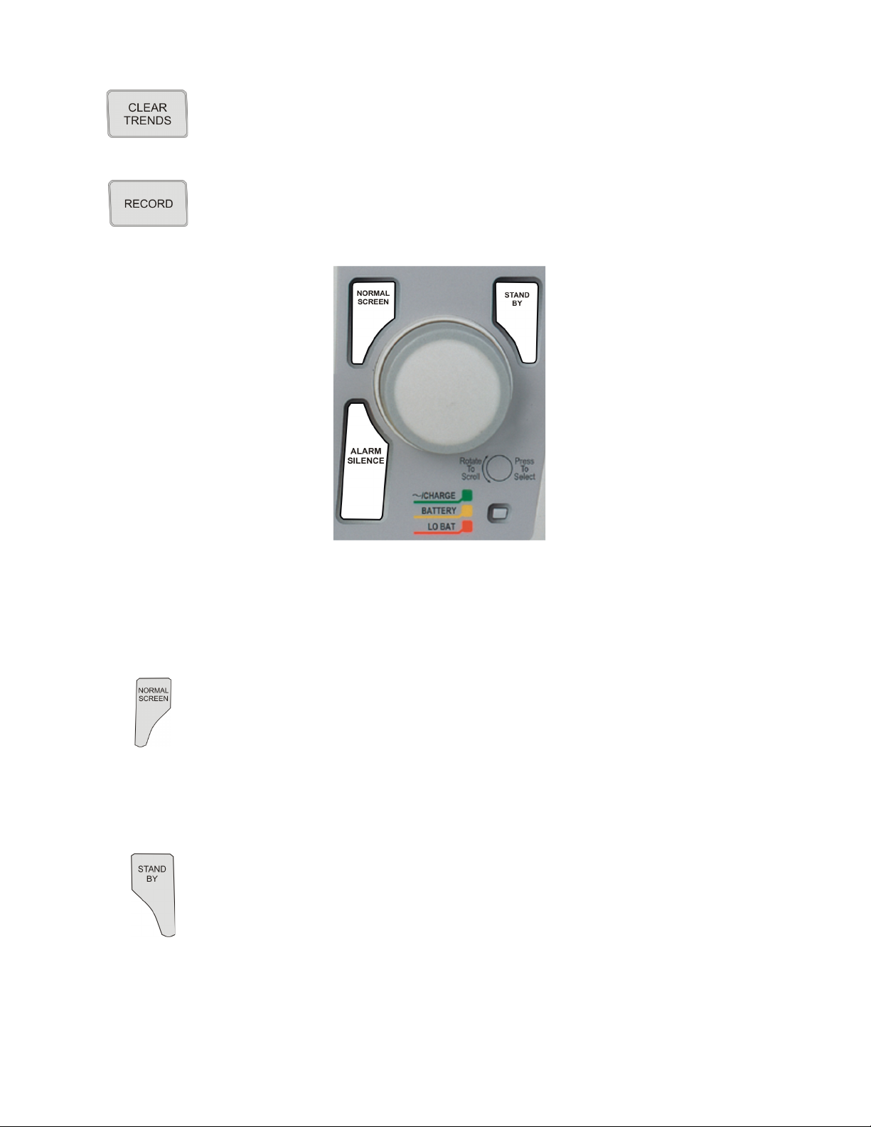
Figure 1-5. The Bottom Keypad Set
d. The Bottom Keypad Set. (See Figure 1-5) The bottom keypad set is not grouped like
the top and middle, but are grouped around the Rotary Knob. There are three push keys
in this set (NORMAL SCREEN, STANDBY and ALARM SILENCE) which
provide direct control of operational features of the monitor. The three push keys are
described below.
(1) NORMAL SCREEN. Pressing the NORMAL SCREEN key returns the
3160 MRI Physiological Monitoring System from any menu to the normal
screen.
(2) STANDBY. Pressing the STANDBY key places the 3160 MRI
Physiological Monitoring System into the Standby Mode. The monitor stays
in Standby Mode until the STANDBY key is pressed a second time. Except
for the three (3) key features given below, the monitor operates normally by
continuing to provide current patient information on the Display Screen.
While in Standby Mode:
• All audible alarms and nurse call are disabled. The disabled alarms
are indicated on the screen by the “X” through the bell shaped
• Active NIBP automatic measurements and STAT Mode
• No automatic printout is generated.
• Default NIBP inflation pressures will be used for all manual NIBP
Alarm Status Symbol.
measurements are suspended.
readings.
1-6

(3) Alarm Silence Key. Pressing the ALARM SILENCE key, when the audible
alarms are enabled (as denoted by the absence of the “X” through the bell
shaped Alarm Status Symbol), will affect the monitor as described below:
WARNING
An active silenced alarm may not be accompanied by an Alarm Silence message or an “S” in the
Alarm Bell icon if the Alarm Hold sequence has been activated, or if a subsequent additional alarm
has occurred and self-corrected.
(a) Alarm Silenced. Any new alarm conditions will cause the Alarm to
reactivate and will also activate the Nurse Call Alarm.
In addition, while alarms are silenced the following conditions
apply:
• Unlatched Alarms. If the alarm system has been set to
UNLATCHED in the ALARMS Menu and an Alarm Limit
is violated, pressing the ALARM SILENCE key will
silence the Alarm Tone turns off the Nurse Call Alarm and
puts the letter “S” in the Alarm Bell when an active Alarm
Limit has been violated. While the parameter continues to
violate its limits, the numerics of the violating parameter
continue to flash on the screen.
• Latched Alarms. If the alarm system has been set to
LATCHED in the ALARMS Menu and an Alarm Limit is
violated, while the parameter continues to violate its limits,
pressing ALARM SILENCE key stops the Alarm Tone,
but the numerics remain red and continue to flash, even
after the parameter returns to within its Alarm Limits.
• ALARM HOLD. If the ALARM SILENCE key is pressed
when the Alarm Tone is enabled but no alarm condition
currently exists, a “SOUND ON HOLD” message appears
in the upper center of the screen with a count down timer
starting at 180 (counting down at a 1 second rate) denoting
that the Alarm Tone is being temporarily held silent. In
addition, an “H” will appear in the Alarm Status Symbol to
further alert the operator that the Alarm System is on Hold.
If the Alarm Tone is sounding, the first pressing of the
ALARM SILENCE key stops the Alarm Tone, turns off
the Nurse Call Alarm, and puts the letter “S” in the Alarm
Bell, and a second pressing enables Alarm Hold.
The monitor automatically exits alarm hold after three
minutes, and the “SOUND ON HOLD” message
disappears from the screen, reactivating the Alarm Tone
(remember that a current alarm condition, which has been
silenced, will not sound again unless the condition returns
within limits and then violates the limit again. Also
remember that a silenced alarm may not be accompanied by
the Alarm Silence message). Pressing the ALARM
SILENCE key before the three minute period is over will
also reactivate the Alarm Tone and nurse call alarm and
remove the “SOUND ON HOLD” message from the
screen.
1-7
The user is able to put alarms on hold (SOUND ON
HOLD) only when the Alarm Tone is active (no X appears
in the bell symbol in the upper left of the screen). Alarm
Hold is useful for temporarily disabling the Alarm Tone.
This might be useful, for example, when changing ECG
leads or for any user activity which might cause a “false”
alarm.
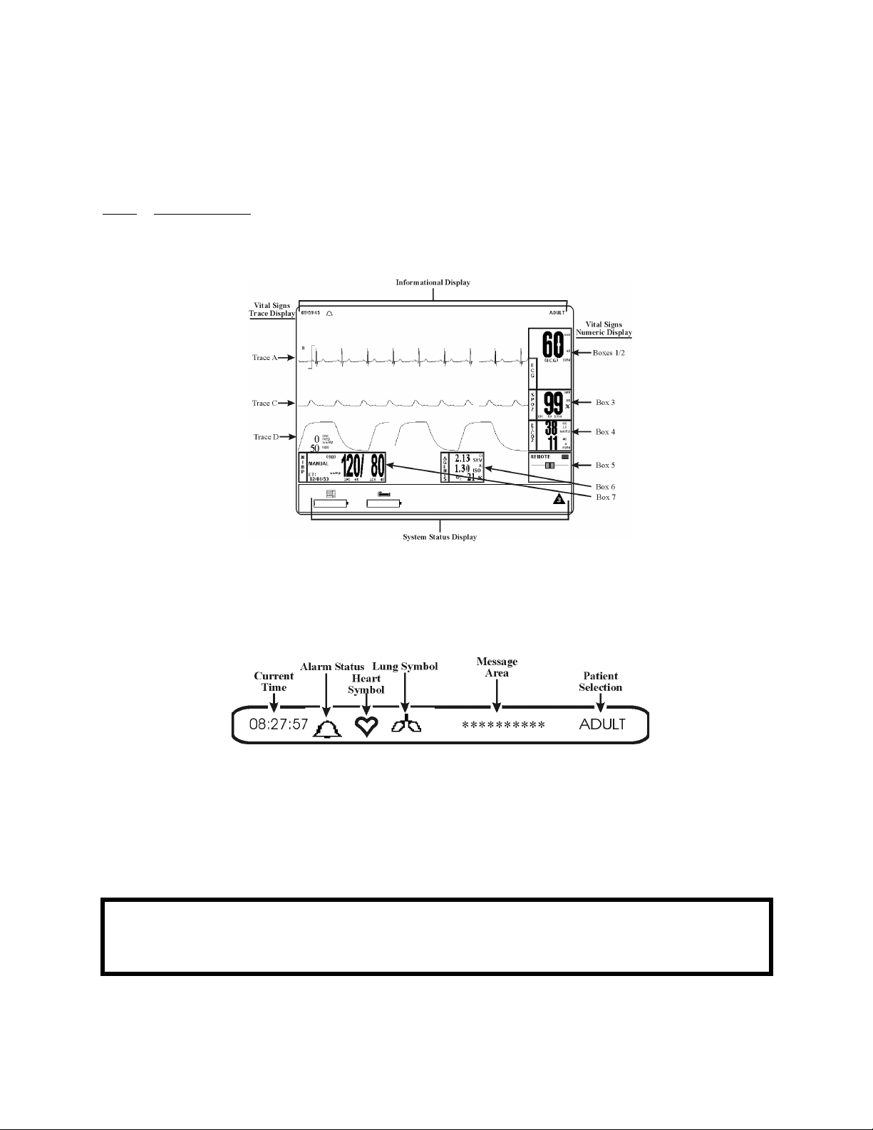
1.4.2
Informational Display, 2) the Vital Signs Trace Display, 3) the Vital Signs Numeric Display and 4) the
Status Display. The entire display screen, with its four different display groups, is called the “Normal
Screen.” The four display areas are described below.
DCU Display. The DCU display screen (See Figure 1-6) displays four groups of data: 1) the
Figure 1-6. The Normal Screen
a. Informational Display. (See Figure 1-7) The Informational Display is located at the
top of the Normal Display. This display provides the operator with the current time, the
Alarm Status Bell Symbol, a flashing Heart Rate Symbol, a flashing Lung Symbol, any
current user messages and the current Patient Selection.
Figure 1-7. The Informational Display
(1) Time. The current time is displayed in a 12 or 24 hour format (hh:mm:ss). The
time, date and clock mode (12 or 24 hour) is adjusted in the TIME Menu.
(2) Alarm Status Symbol. The 3160 MRI Physiological Monitoring System
sounds an Alarm Tone when any monitored parameter violates its
programmed Alarm Limits. The status of the Alarm Tone is indicated by the
bell shaped Alarm Status Symbol.
WARNING
When an “X” appears in the Alarm Status Symbol, the audible Alarm Tone will NOT sound for any
reason.
1-8
(a) The letter “H” appearing in the bell indicates that the alarms have been
placed on temporary Hold with the ALARM SILENCE key.
Similarly, during power-up the “SOUND ON HOLD” message
displayed in the center of the screen indicates that the Alarm Tone is
temporarily placed on hold. A 180 second countdown timer is also
displayed under the message.
(b) The letter “X” appearing in the bell symbol indicates that the alarms
have been turned off from the ALARMS Menu or that Standby Mode
has been engaged. In this case the Alarm Tone will not sound for any
reason.
(c) The letter “S” appearing in the bell indicates that a current alarm has
been silenced with the ALARM SILENCE key. This feature will
disable only the alarms that were current when the ALARM
SILENCE key was pressed, any new alarms will cause the Alarm
Tone to sound.
(3) Heart Symbol. The Heart Symbol flashes on the screen each time a heart beat
is detected. A tone is sounded at the same time (unless turned off in the ECG
Menu or the SPO2 Menu).
(4) Lung Symbol. The Lung Symbol flashes on the screen at the end of each
detected breath whenever the EtCO2 monitoring feature is turned on (if
available).
(5) Messages. These messages assist the operator in various aspects of the
operation of this monitor.
(6) Patient Selection. Indicates the selected patient (ADULT or NEONATAL) for
the ECG and NIBP monitoring features.
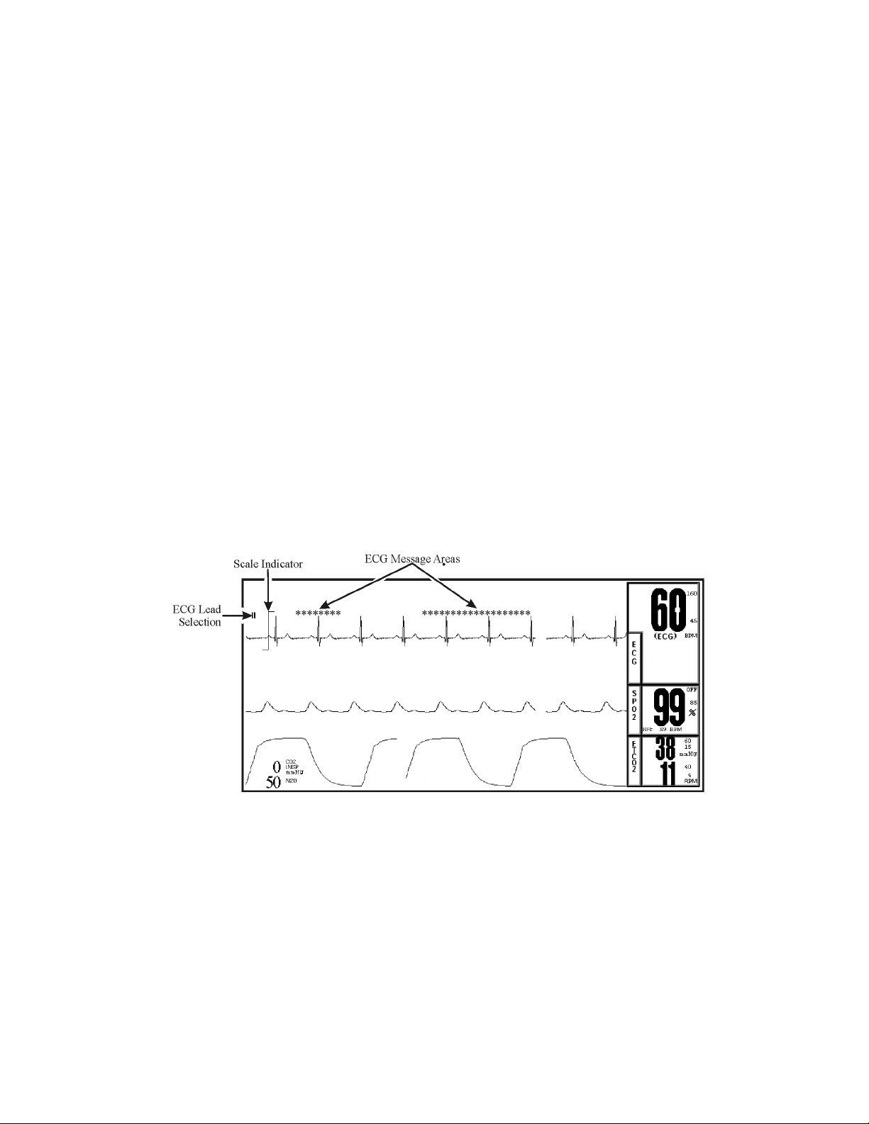
Figure 1-8. The Vital Signs Trace Display
b. Vital Signs Trace Display. (See Figure 1-8) The Vital Signs Trace Display is located
in the middle of the Display Screen. This Display provides the operator with a trace of
the selected parameters and also contains Numerical Vital Sign indications for the
selected patient parameter.
(1) The Vital Signs Trace Display portion of the screen is divided into six separate
trace areas. When turned on, the traces are fixed on the screen and updated with
an Erase Bar. When a trace has been turned off, that portion of the screen is
blank. The numeric values for each trace appear near the right screen
boundary.
(2) If the value is greater than or equal to a maximum calculable value, “OVR”
(Over Range) is alternately displayed with the numeric value.
1-9
(3) TRACE A, C and D are assigned according to parameter and come on/go off
as parameters are turned on or off. Trace B is the location used for the
“Freezing” of a waveform and is not assigned a parameter.
The following is a description of each Trace:
(4) TRACE A. The ECG trace is displayed in this position, unless turned off from
either the ECG Menu or the SETUPS Menu. The main menu for this trace and
for the Heart Rate are brought up with the selection of the ECG Menu-Select
Icon.
(a) The heart rate is displayed near the right screen boundary in the Trace
A position. The numerics turn Red and flash if a Heart Rate Alarm
Limit is violated. The color of the numerics is that of the selected HR
source.
(b) The annotation below the heart rate value indicates the source of the
heart rate, as selected from the ECG Menu, the NIBP Menu and the
SPO2 Menu. Heart rate source choices are AUTO, ECG, SPO2 and
NIBP (there is an ART option shown but selecting this item will bring
up a message alerting the operator that the option is not available).
(c) A red flashing numeric value on the screen indicates that an alarm for
this value has been violated. This provides a visual indication of alarm
violations, even when the Alarm Tone is turned off.
(d) If AUTO is selected as the HR SOURCE, the highest-priority active
input is utilized for displaying the heart rate, in the order listed above.
The ECG trace must be off, or lead fail present, for the Auto source not
to be the ECG trace.
(e) If the monitor does not find a valid heart rate source when set to
AUTO and NIBP is OFF, the heart rate is annotated with “NONE.”
(f) The displayed lead for the ECG 1 is indicated near the left screen
boundary.
(g) A scale indicator is displayed near the left screen boundary in the ECG
waveform area(s). It represents a 1mV amplitude in the currently
selected scale.
(5) TRACE B. Trace B displays a frozen waveform for detailed analysis.
(6) TRACE C. Trace C displays the SpO2 waveform (if SpO2 enabled).
(7) TRACE D. Trace D displays the Respiration waveform (if EtCO2 enabled).
Figure 1-9. The Vital Signs Numeric Display
c. Vital Signs Numeric Display. (See Figure 1-9) The Vital Signs Numeric Display is
located at the bottom and right of the display screen. This Display is divided with
boxes that provide the operator with numerical indications for NIBP and Agents.
1-10
 Loading...