

Invivo 3155 User manual


Invivo Research, Incorporated
®
Millennia
3155A/3155MVS Monitor
Operations Manual


TABLE OF CONTENTS
Paragraph Number Page Number
List of Figures...........................................................................................................................................iv
List of Tables.............................................................................................................................................. v
Equipment Classification ....................................................................................................................... v
Precautions................................................................................................................................................vi
User Responsibility ................................................................................................................................. xi
Accessory List..........................................................................................................................................xii
1.0 INTRODUCTION.......................................................................................................... 1-1
1.1 Product Description ......................................................................................................... 1-1
1.1.1 System Parameters............................................................................................... 1-2
1.1.2 User Interface....................................................................................................... 1-2
1.1.3 Versatility ............................................................................................................. 1-2
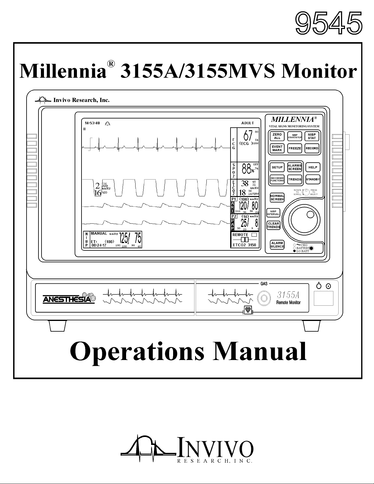
1.2 Controls............................................................................................................................ 1-2
1.2.1 Front Panel Controls ............................................................................................ 1-2
1.2.2 The Side Panel ..................................................................................................... 1-7
1.2.3 Back Panel Connections and Inputs..................................................................... 1-7
1.3 Display ............................................................................................................................. 1-7
1.3.1 Informational Display .......................................................................................... 1-8
1.3.2 Vital Signs Trace Display .................................................................................... 1-9
1.3.3 NIBP, Agents and Remote Display.................................................................... 1-10
1.4 Yes/No Menu ................................................................................................................. 1-11
1.5 Cleaning ......................................................................................................................... 1-11
1.5.1 Cleaning Accessories......................................................................................... 1-12
2.0 INSTALLATION........................................................................................................... 2-1
2.1 Introduction...................................................................................................................... 2-1
2.2 Monitor Installation ......................................................................................................... 2-1
2.2.1 Monitor Mounting................................................................................................ 2-1
2.2.2 Monitor Location ................................................................................................. 2-1
2.2.3 Preparing the 3155A/3155MVS Monitor for Use ............................................... 2-1
2.2.4 Monitor Start Up .................................................................................................. 2-2
2.2.5 3150(M) and 3155A/3155MVS Remote Monitor Communication .................... 2-2
2.3 Software Installation ........................................................................................................ 2-4
2.3.1 Program Update/Upgrade .................................................................................... 2-4
2.3.2 Monitor Setup Storage ......................................................................................... 2-5
2.3.3 Monitor Setup Recall ........................................................................................... 2-5
3.0 MONITOR PREPARATION FOR USE..................................................................... 3-1
3.1 Introduction...................................................................................................................... 3-1
3.2 SETUPS Menu................................................................................................................. 3-1
3.2.1 Recall Setups........................................................................................................ 3-1
3.2.2 Store Setups ......................................................................................................... 3-2
3.2.3 Parameter Selection ............................................................................................. 3-3
3.2.4 Display Setup....................................................................................................... 3-4
3.2.5 Sound Adjust........................................................................................................ 3-5
3.2.6 Patient .................................................................................................................. 3-6
i

TABLE OF CONTENTS
Paragraph Number Page Number
3.2.7 Set Time............................................................................................................... 3-6
3.2.8 Default Setups...................................................................................................... 3-7
3.2.9 Sweep Speed ........................................................................................................ 3-7
3.2.10 Respiration Speed ................................................................................................ 3-7
3.2.11 Service (Bio-Med) ............................................................................................... 3-7
3.2.12 Return................................................................................................................. 3-10
3.3 Store/Recall Setups ........................................................................................................ 3-10
3.4 Monitor Initialization..................................................................................................... 3-10
3.4.1 Default Initialization .......................................................................................... 3-10
3.4.2 Pre-Configured Initialization ............................................................................. 3-11
4.0 PATIENT PARAMETERS........................................................................................... 4-1
4.1 Introduction...................................................................................................................... 4-1
4.2 ECG Monitoring .............................................................................................................. 4-1
4.2.1 Associated Waveforms and Displays................................................................... 4-1
4.2.2 The ECG Menu.................................................................................................... 4-1
4.2.3 Alarm Limits........................................................................................................ 4-4
4.2.4 Trended Data........................................................................................................ 4-4
4.2.5 ECG Messages..................................................................................................... 4-4
4.3 Invasive Pressure Monitoring .......................................................................................... 4-5
4.3.1 Associated Waveforms and Displays................................................................... 4-5
4.3.2 The Invasive Pressure Menu................................................................................ 4-5
4.3.3 Alarm Limits........................................................................................................ 4-7
4.3.4 Trended Data........................................................................................................ 4-7
4.4 Non-Invasive Blood Pressure (NIBP) Monitoring .......................................................... 4-7
4.4.1 Theory of Oscillometric Measurement ................................................................ 4-8
4.4.2 Associated Displays............................................................................................. 4-9
4.4.3 The NIBP Menu................................................................................................. 4-10
4.4.4 NIBP Menu Options .......................................................................................... 4-10
4.4.5 Using the Automatic Interval Mode .................................................................. 4-12
4.4.6 Manually Starting/Stopping a Reading Cycle.................................................... 4-12
4.4.7 Stat Mode Operation.......................................................................................... 4-12
4.4.8 Alarm Limits...................................................................................................... 4-13
4.4.9 Adult vs. Neonatal Mode Operation .................................................................. 4-13
4.4.10 Trended Data...................................................................................................... 4-13
4.5 SpO2 Monitoring ........................................................................................................... 4-13
4.5.1 Associated Waveforms and Displays................................................................. 4-13
4.5.2 SpO2 Menu ........................................................................................................ 4-14
4.5.3 Alarm Limits...................................................................................................... 4-15
4.5.4 Trended Data...................................................................................................... 4-15
4.6 End-Tidal CO2 (ETCO2) Monitoring............................................................................ 4-15
4.6.1 Patient and Tubing Preparation.......................................................................... 4-15
4.6.2 Associated Waveforms and Displays................................................................. 4-16
4.6.3 ETCO2 Menu..................................................................................................... 4-17
4.6.4 Calibration of CO2/N2O Measurement System ................................................ 4-17
4.6.5 Alarm Limits...................................................................................................... 4-17
4.6.6 Trended Data...................................................................................................... 4-17
ii

TABLE OF CONTENTS
Paragraph Number Page Number
4.7 Anesthetic Agent/Oxygen Monitoring........................................................................... 4-18
4.7.1 Patient and Tubing Preparation.......................................................................... 4-18
4.7.2 Associated Displays........................................................................................... 4-18
4.7.3 Agent Menu ....................................................................................................... 4-19
4.7.4 Gas Calibration .................................................................................................. 4-19
4.7.5 Alarm Limits...................................................................................................... 4-20
4.7.6 Trended Data...................................................................................................... 4-20
4.7.7 Agent/O2 Messages ........................................................................................... 4-20
4.7.8 Oxygen Sensor Replacement ............................................................................. 4-20
5.0 PRINTING AND TRENDING ..................................................................................... 5-1
5.1 Introduction...................................................................................................................... 5-1
5.1.1 Record Key .......................................................................................................... 5-1
5.2 The RECORDER Menu................................................................................................... 5-2
5.3 Printing Charts ................................................................................................................. 5-3
5.3.1 Strip Chart Printouts ............................................................................................ 5-3
5.3.2 Tabular Chart Printouts ........................................................................................ 5-4
5.3.3 System Data Report ............................................................................................. 5-5
5.4 Loading Printer Paper ...................................................................................................... 5-5
5.5 Trending Feature.............................................................................................................. 5-5
5.5.1 HISTORY Menu Options .................................................................................... 5-5
5.5.2 Theory of Operation............................................................................................. 5-6
5.5.3 Trend Options ...................................................................................................... 5-7
6.0 ALARMS ........................................................................................................................ 6-1
6.1 Introduction...................................................................................................................... 6-1
6.2 Alarm Limits.................................................................................................................... 6-1
6.2.1 Default (Pre-Set) Alarm Limits ........................................................................... 6-1
6.2.2 Range of High and Low Alarm Limits ................................................................ 6-1
6.3 Alarms Menu ................................................................................................................... 6-2
6.3.1 Individual Parameter Alarm Limits Box ............................................................. 6-7
6.4 Turning Alarms Off on Individual Parameters ................................................................ 6-7
6.5 Alarm Violations.............................................................................................................. 6-7
6.6 Adjusting the Alarm Tone Volume .................................................................................. 6-7
6.6.1 Disabling the Alarm Tone .................................................................................... 6-8
6.7 Standby Mode .................................................................................................................. 6-9
7.0 BATTERY OPERATION............................................................................................. 7-1
7.1 Introduction...................................................................................................................... 7-1
7.2 Battery Location and Access ........................................................................................... 7-1
7.3 Loading and Unloading Battery(s) .................................................................................. 7-1
7.4 Battery Charging.............................................................................................................. 7-1
7.5 Battery Operation Time ................................................................................................... 7-1
7.5.1 Battery Low Indication ........................................................................................ 7-1
7.5.2 Maintaining Battery Life ..................................................................................... 7-1
7.6 Battery Replacement........................................................................................................ 7-1
iii

TABLE OF CONTENTS
Paragraph Number Page Number
Appendix A. Specifications ................................................................................................................A-1
Appendix B. Repair ............................................................................................................................. B-1
Appendix C. Warranty........................................................................................................................C-1
Appendix D. Declaration of Conformity.........................................................................................D-1
Appendix E. KpA to mmHg Conversion Chart ............................................................................ E-1
Appendix F: List of Symbols ............................................................................................................. F-1
LIST OF FIGURES
Figure Number Page Number
1-1 The Front Panel................................................................................................................ 1-2
1-2 The Direct Control Keys.................................................................................................. 1-3
1-3 Menu-Select and Operation Keys .................................................................................... 1-4
1-4 The Back Panel ................................................................................................................ 1-7
1-5 The Normal Screen .......................................................................................................... 1-8
1-6 The Informational Display............................................................................................... 1-8
1-7 The Middle Screen Vital Signs Trace Display ................................................................ 1-9
1-8 The Bottom Vital Signs Numeric Display..................................................................... 1-10
3-1 The SETUPS Menu ......................................................................................................... 3-1
3-2 The RECALL SETUPS Menu......................................................................................... 3-2
3-3 The STORE SETUPS Menu........................................................................................... 3-3
3-4 The PARAMETER SELECTION Menu......................................................................... 3-3
3-5 The SOUND ADJUST Menu .......................................................................................... 3-4
3-6 The SET TIME Menu ...................................................................................................... 3-6
3-7 The SERVICE (BIO-MED) Menu .................................................................................. 3-7
3-8 The SYSTEM CONFIG Menu ........................................................................................ 3-8
4-1 ECG Display .................................................................................................................... 4-1
4-2 The ECG Menu................................................................................................................ 4-2
4-3 The ECG SCALE Menu .................................................................................................. 4-2
4-4 The HR SOURCE Menu.................................................................................................. 4-3
4-5 Invasive Pressure Display................................................................................................ 4-5
4-6 The P1 Menu (ART Selected) ......................................................................................... 4-6
4-7 Invasive Pressure SET LABEL Menu ............................................................................. 4-6
4-8 Oscillometric Measurement Method ............................................................................... 4-8
4-9 The NIBP Display............................................................................................................ 4-9
4-10 The NIBP Menu............................................................................................................. 4-10
4-11 The NIBP INTERVAL Menu........................................................................................ 4-10
4-12 The HISTORY Menu..................................................................................................... 4-11
4-13 The SpO2 Display.......................................................................................................... 4-13
4-14 The SpO2 Menu............................................................................................................. 4-14
4-15 Patient Sample Circuit ................................................................................................... 4-15
4-16 The ETCO2 Display ...................................................................................................... 4-16
4-17 The ETCO2 Menu ......................................................................................................... 4-17
4-18 The AGENT Display ..................................................................................................... 4-18
4-19 Oxygen Sensor Installation Diagram............................................................................. 4-21
5-1 The RECORDER Menu................................................................................................... 5-1
iv

LIST OF FIGURES
Figure Number Page Number
5-2 Sample Strip Chart........................................................................................................... 5-3
5-3 Sample Tabular Chart ...................................................................................................... 5-4
5-4 System Data Report ......................................................................................................... 5-4
5-5 Loading the Printer Paper ................................................................................................ 5-5
5-6 The HISTORY Menu....................................................................................................... 5-5
5-7 The MULTI TRENDS Menu........................................................................................... 5-6
5-8 The Trend SELECT Menu............................................................................................... 5-7
5-9 Sample Mult Trends Printout........................................................................................... 5-8
6-1 The ALARMS Menu ....................................................................................................... 6-4
6-2 Anesthetic Agents Alarm Limits Menu ........................................................................... 6-5
LIST OF TABLES
Table Number Page Number
6-1 Alarm Limit Factory Default Settings.....................................................................................6-2
6-2 Range of Alarm Limits .................................................................................................... 6-3
EQUIPMENT CLASSIFICATION
Classification according to IEC-601-1
According to the type of protection against
electrical shock:
According to the degree of protection against
electrical shock:
According to the degree of protection against
harmful ingress of water:
According to the methods of sterilization or
disinfection:
According to the mode of operation: Continuous operation.
Equipment not suitable for use in the presence of a flammable anesthetic mixture with air or
with oxygen or nitrous oxide.
Class I equipment.
Type CF (defibrillator-proof) equipment.
Ordinary equipment (enclosed equipment
without protection against ingress of water).
Non0sterilizable. Use of Liquid surface
disinfectants only.
v

Precautions
General
Federal law in the USA or Canada restricts this device to sale by, or on the order of, a physician.
The Millennia
3150M monitor is factory set to communicate only with the specific monitor it came with.
®
3155A/3155MVS Monitor supplied with your Omni-TrakTM 3150/Magnitude
TM
The Omni-TrakTM 3150/MagnitudeTM 3150M MRI Patient Monitoring System is comprised
of the 3150(M) and a Millennia
TrakTM 3150/Magnitude
®
3155A/3155MVS Remote Monitor. Always operate the Omni-
TM
3150M MRI Patient Monitor with its designated remote monitor.
The accuracy of the measurements can be affected by the position of the patient, the patient’s
physiological condition, and other factors. Always consult a physician for interpretation of
measurements made by this monitor.
To avoid monitor fall, secure monitor on the shelf or bracket prior to use.
An explosion hazard exists if this monitor is used in the presence of flammable anesthetics.
The operator should read and thoroughly understand this manual completely before attempting to
operate the Millennia
®
3155A/3155MVS Monitor.
If any system failure occurs (e.g. an unexplained continuous audible alarm) remove the monitor
from use, and refer it to qualified service personnel.
When an “X” appears in the Alarm Bell symbol, the audible alarm tone will not sound for any
reason.
Perform operational checkout before each use. If monitor fails to function properly, refer to
qualified service personnel.
For safe and accurate operation, use only recommended Invivo Research patient cable, lead wires,
cuffs, hoses, sensors, tubing, etc. A listing of these can be found in the Accessory Listing within
the 3150(M) manual (Part Number 9538), or by contacting Invivo Research directly.
For continued operation, always connect the monitor to AC Main Power through the AS153 AC
Power Adapter when a Low Battery indication occurs. Failure to do this can lead to interruption
of monitoring and/or damage to the monitor’s battery(s).
The system may not conform to all performance specifications if stored or used outside the
environmental specifications identified in Appendix A in the rear of this manual.
Do not apply any unnecessary pressure to the screen area of the monitor. Severe pressure applied
to this portion of the monitor could result in damage or failure of this screen.
All equipment not complying with IEC 601-1 should be placed outside the patient environment.
Only connect IEC 601-1 compliant equipment to this monitor. To avoid potentially hazardous
leakage currents, always check the summation of leakage currents when several items of
equipment are interconnected.
For proper equipment maintenance, perform the service procedures at the recommended intervals
as described in the monitor’s service manual.
Single use devices should never be reused.
Organic vapors (e.g. from cleaning agents) in sampling line or room air may alter anesthetic agent
readings.
Alcohol in patient's breath may modify the anesthetic agent readings.
vi

Precautions
Electrical Safety
To avoid an electrical hazard, never immerse the unit in any fluid or attempt to clean it with liquid
cleaning agents. Always disconnect monitor from DC Main Power before performing cleaning or
maintenance.
Shock hazard exists if operated without chassis cover. Refer servicing to qualified service
personnel only.
For continued protection against fire hazard, replace fuses with same type and rating only.
If the integrity of the earth conductor of the AC mains power cable is in doubt, operate the
monitor on internal battery power until proper earth connection is confirmed.
Avoid use of electrical power extension cords. Electrical power cords may create a safety hazard
by compromising the grounding integrity of the monitor.
If monitor becomes accidentally wet during use, discontinue operation of the monitor until all
affected components have been cleaned and permitted to dry completely. Contact your local
Invivo Research, Inc. representative if additional information is required.
This monitor and its listed accessories may be safely powered by the voltages 110-120/220-240 ~
having a frequency of 50 or 60 Hz.
Occupational Safety
Connect the sample gas outlet on the monitor's rear panel to scavenging system to prevent
pollution of room air.
Handle the Patient Sampling Line and its contents as you would any body fluid. Infectious hazard
may be present.
MRI Use Precautions
Certain components of this device will be affected by the magnetic and radio-frequency fields
present in your MRI System. Confer with your MRI physicist and/or Radiology staff to identify
the proper placement and use areas for the monitor and its accessories, as defined on the monitor
or accessory labeling. Failure to properly place the monitor and its accessories in the Magnet
Room will result in monitor failure, and possible patient or user injury. Always position the
Millennia® 3155A/3155MVS Monitor at, or outside, the 1000 Gauss (0.1T) field line of the MRI
system. If brought closer than the 1000 Gauss Field Line, monitor damage (failure to operate)
may result.
TM
Always verify proper communication of the Omni-Trak
3150/MagnitudeTM 3150M MRI
Patient Monitor with the Millennia® 3155A/3155MVS Monitor prior to patient use.
MRI Magnet Room Placement. The Omni-TrakTM 3150 MRI/MagnitudeTM 3150M MRI
Patient Monitor is designed to be used in conjunction with a remotely located Millennia
3155A/3155MVS Monitor. The Omni-TrakTM 3150/MagnitudeTM 3150M MRI Patient
Monitor is specially designed not to interfere with MRI operations and may be used inside the
MRI Magnet Room in any location at or outside the 5000 Gauss (0.5T) Field Line of the MRI
System. If brought closer than the 5000 Gauss Field Line, the NIBP monitor pump and ETCO2
pump may fail to operate.
®
vii

Precautions
ECG
An inoperative ECG monitor is indicated by absence of an ECG waveform and a simultaneous
Lead Fail alarm.
Heart rate values may be adversely affected by cardiac arrhythmia, or by operation of electrical
stimulators.
For other ECG related precautions, refer to the 3150(M) Monitor Operations Manual (IRI Part
Number 9538).
NIBP
Always use recommended NIBP cuffs and hoses. Avoid compression or restriction of NIBP cuff
hose.
For other NIBP related precautions, refer to the 3150(M) Monitor Operations Manual (IRI Part
Number 9538).
SpO2
The numeric measurement values are updated every 1 second on the monitor display.
The pulse oximeter feature in this monitor is designed to display functional SpO2 values.
The pulse oximeter pulsatile waveform is not proportional to the pulse volume, but adjusts the
waveform amplitude as needed for proper viewing.
All monitor alarms are categorized as medium priority, unless otherwise specified.
For other SpO2 related precautions, refer to the 3150(M) Monitor Operations Manual (IRI Part
Number 9538).
EtCO2
Always select the appropriate EtCO2 gas sampling flow rate for the patient being monitored.
Verify that the patient’s breathing efforts and timing coincide with the monitor’s waveform
before completion of the patient set-up.
The N2O measurements are automatically pressure compensated over an ambient pressure
minimum range from 645 to 795 mmHg.
The EtCO2/N2O measurement displays the sampled value within 1 second of when the gas was
sampled.
The alarm tone volume exceeds 60 dBA at a distance of 1 meter when the alarm tone volume
adjustment is set above selection number 4.
Frequently inspect the EtCO2 patient tubing for proper gas flow. Avoid kinking of the EtCO2
patient tubing that can result in leaking, reduction, or cut-off of the sample gas flow. Inaccurate
gas measurements could result.
EtCO2 patient tubing and its associated components are intended for single-patient use only.
Avoid cleaning or disinfecting these items for reuse. Inaccurate gas measurements could result.
To prevent inaccurate or missed readings, keep the EtCO2 patient tubing clear of any moving
mechanisms which may kink, cut or dislodge the patient tubing.
Avoid connecting the EtCO2 calibration gas canister to the monitor by any method other than
with the designated calibration tubing. Connecting by any other method could invalidate the
calibration, and/or damage the monitor.
Respiration rate measurement errors could result during ventilation rates above 80 breaths per
minute.
viii

Precautions
Anesthetic Agents
Inadequate ventilation of the monitor may cause inaccurate readings or damage to electronic
components.
Ensure that the exhaust gas is not removed from the monitor under too strong suction. To prevent
suction, there must always be an opening to the room air. Strong suction may change the
operating pressure of the monitor and cause inaccurate readings or internal damage.
Inspect waste gas line for deterioration on a routine basis. Replace as needed.
Remove sampling line from patient airway whenever nebulized medications are being delivered.
Use only Invivo Research, Inc. sampling lines and accessories; other sampling lines may cause
inaccurate readings and malfunctions.
In Desflurane Gas Mixtures, the change in concentration of the other anesthetic may become
clinically significant before a gas mixture alarm is given.
Some Hydrocarbons (e.g. Acetone, Methane) may cause a mixed agent alarm to occur.
Replace the sampling line and filter between each patient use.
Routinely inspect the hose assemblies for proper attachment and orientation. Replace hose
assemblies with cracks, holes, tears, cuts, etc. that could cause leaks in the system. If hose
assemblies with damage which could result in leaks are used, prolonged and/or inaccurate patient
readings could result.
If questionable oxygen or anesthetic agent gas measurements are observed, recheck patient
connections, anesthesia gas machine and/or vaporizer before re-adjusting oxygen or anesthesia
delivery.
Always respond to patient tubing disconnect alarms immediately to prevent lapse in patient
monitoring.
Routinely verify the monitor’s internal barometric pressure reading with local conditions during
the initial start-up period.
Gas mixtures of Desflurane and Sevoflurane will not cause a multiple agent alarm. The optical
filters used to determine Desflurane and Sevoflurane are very similar, making it very difficult to
determine the presence of Desflurane and Sevoflurane at the same time. The identification could
be either Desflurane or Sevoflurane in concentration values (Fi and ET) greater than either of the
actual concentrations of Desflurane and Sevoflurane.
During the 15 minute warm-up with no sample line connected to the monitor it is possible to have
a false identification and value display of Enflurane.
With no gas reading (Agent Icon box with white X for agent identification and agent values of “--
-“) when Agent Vaporizer is first turned on, it may take 30 seconds to 1.5 minutes for agent
identification and reading to be displayed. Once identification is established, changes in
concentration are virtually immediate. With a 200% change in concentration, an auto Zero will
occur, and full accuracy of the changed concentration will be accomplished within approximately
30 seconds.
Whenever the Millennia® 3155A’s Agent sensor changes from steady state condition, the
®
Millennia
3155A will perform an auto zero to restabilize the sensor readings. During this time,
15 seconds to 1.5 minutes, it is possible for a false identification and concentration value to occur.
Examples are as follows:
a. No gas, during warm-up and when sample line is disconnected.
b. Applying sample line for the first time.
c. When switching from one Agent to another.
d. Applying N2O in concentrations of 70% or more.
e. Going from N2O of greater than 50% to 0%.
f. When going from high Agent concentrations to low or off.
ix

Precautions
Pressures
Air that may be trapped within the pressure transducer or its associated tubing should be removed
by flushing the system following established hospital or catheter lab procedures.
The fluid within the pressure transducer system is a conductive connection to the patient, and
should not contact other conductive parts, including earth ground.
Other
This product, or any of its parts, should not be repaired other than in accordance with written
instructions provided by Invivo Research, Inc., or altered without prior written approval of Invivo
Research, Inc.
The user of this product shall have the sole responsibility for any malfunction which results from
improper use, faulty maintenance, improper repair, damage, or alteration by anyone other than
Invivo Research Inc., or its authorized service personnel.
This monitor is equipped with a demonstration mode which displays simulated electronic patient
data for training or demonstration purposes. Do not attach a patient to the monitor whenever this
simulation is present on the monitor display (“SIMULATION” can also be seen in the screen
center). Failure to properly monitor the patient could result.
The patient connector inputs for all parameters are protected against the use of a defibrillator by
internal circuitry, and when the recommended patient cables or accessories are used. The use of
this circuitry and these recommended cables and accessories also protects against the hazards
resulting from use of high frequency surgical equipment.
There are no known electromagnetic or other hazardous interference between the monitor and
other devices including MRI Scanners. However, care should be taken to avoid the use of cellular
phones or other unintended radio-frequency transmitters in the proximity of the monitoring
system.
This monitor uses rechargeable batteries which contain lead, which must be recycled, or disposed
of properly. For proper disposal methods, contact your local Invivo Research, Inc. representative
or distributor.
x

USER RESPONSIBILITY
This product will perform in conformity with the description contained in this operators manual
and accompanying labels and/or inserts, when assembled, operated, maintained and repaired in
accordance with the instructions provided. This product must be checked and calibrated
periodically. A malfunctioning product should not be used. Parts that are broken, missing, plainly
worn, distorted or contaminated should be replaced immediately. Should such repair or
replacement become necessary refer unit to qualified service personnel. This product or any of its
parts should not be repaired other than in accordance with written instructions provided by the
manufacturer, or altered without written approval of Invivo Research, Incorporated (IRI). The
user of the product shall have the sole responsibility for any malfunction which results from
improper use, faulty maintenance, improper repair, damage or alteration by anyone other than
Invivo Research or Invivo Research authorized service personnel.
Using this Manual. Whenever the various options are discussed, “XXX” is used to indicate a
variable setting. It is required that every operator read this manual completely, including
any patient information in sections about monitoring features the operators monitor does
not have, before attempting to operate the Millennia® 3155A/3155MVS Monitor.
Precautions (listed earlier in this section) cover of wide ranges of information crucial to the safe
monitoring of patients. It is required that every operator read the PRECAUTIONS
completely, including the Precautions associated with monitoring features that the
operators monitor does not have, before attempting to operate the Millennia® 3155A/
3155MVS Monitor.
For further information or assitance with this product:
Invivo Research, Incorporated
407-275-3220 or 800-331-3220
xi

Accessory List
END -TIDAL CO2
Item Description Part Number
ETCO2 Sampling Kit .........................................................................................................................9010D
Contains 20 foot co-extruded sampling tube polyethylene inner core with PVC jacket, Nafion®
tube, elbow adapter, 0.8 micron disk filter.
Nasal ETCO2 Sampling Kit............................................................................................................9010DA
Contains 10 foot co-extruded sampling tube, polyethylene inner core with PVC jacket,
Nafion® tube, elbow adapter, 0.8 micron disk filter.
Nasal ETCO2 Sampling Kit Replacements
Co-extruded Nasal ETCO2 Sampling Line..........................................................................................9028
10 foot co-extruded polyethylene inner core with PVC jacket, male/female locking luer,
package of 50.
Co-extruded Nasal ETCO2 Sampling Line..........................................................................................9041
20 foot co-extruded polyethylene inner core with PVC jacket, male/female locking luer,
package of 25.
Endotracheal Tube Adapter, package of 50..........................................................................................9025
Hydrophobic Disk Filter, 0.8 Micron, Male / Female Locking Luer, package of 50......................... 9026
Nafion® tube, ME dryer (1 replacement) ..........................................................................................9010H
Nasal ETCO2 Supplies
ETCO2 Calibration Gas, aerosol 10% CO2, 50% N2O, Bal. N2.....................................................9010F
Adult Nasal ETCO2 Sampling Cannula 7 foot line............................................................................. 9012
Pediatric Nasal ETCO2 Sampling Cannula 7 foot line .......................................................................9013
Infant Nasal ETCO2 Sampling Cannula 7 foot line ............................................................................9014
Intermediate Infant Nasal ETCO2 Sampling Cannula 7 foot line ......................................................9015
Adult Bifurcated/Divided Cannula-O2 and ETCO2............................................................................9016
7 foot O2 line and 7 foot CO2 line. For simultaneous delivery of oxygen and ETCO2
sampling.
Infant Bifurcated/Divided Cannula -O2 and ETCO2 .......................................................................9016A
7 foot O2 line and 7 foot CO2 line. For simultaneous delivery of oxygen and ETCO2
sampling.
Intermediate Infant Bifurcated/Divided Cannula-O2 and ETCO2 .................................................. 9016B
7 foot O2 line and 7 foot CO2 line. For simultaneous delivery of oxygen and ETCO2
sampling.
Pediatric Bifurcated/Divided ETCO2 Cannula -O2 and ETCO2 .................................................... 9016C
7 foot O2 line and 7 foot CO2 line. For simultaneous delivery of oxygen and ETCO2
sampling.
xii

Accessories
End-Tidal CO2 (Continued)
Item Description Part Number
Nasal ETCO2 Supplies (Continued)
Adapter, Luer Lock, Female/Female....................................................................................................9027
For conversion of Millennia® male front panel connector for use with non-Invivo sampling
lines. Package of 10.
Water Trap Start Up Kit, Disposable ....................................................................................................9436
Includes water trap and connection tubing, Nafion® tube ME dryer, Hydrophobic disk filter
0.08 micron.
Waste Gas Scavenger Line ....................................................................................................................9471
Includes 8 foot waste gas line to redirect the waste gas.
Anesthetic Agent
Anesthetic Oxygen Sensor Kit..............................................................................................................9461
Includes Anesthetic Oxygen Sensor (P/N 9445) and an Anesthetic O2 Sensor Adapter.
Oxygen Sensor, Galvanic......................................................................................................................9445
Inspired 02 Sensor Kit, Disposable....................................................................................................... 9464
Contains a P/N 9445 Oxygen Sensor and allows for measurement of the O2 directly in the
patient airway at the ventilator.
Water Trap Kit, Disposable ................................................................................................................... 9436
Includes water trap and connection tubing, Nafion tube ME dryer, Hydrophobic disk filter 0.08
micron.
Waste Gas Scavenger Line ....................................................................................................................9471
Includes 8 foot waste gas line to redirect the waste gas.
Anesthetic Agent Check Gases:
QC Check Gas: 7% Desflurane, 5% CO2, 60% N2O, 21% O2, Balance N2; 3.7 Liter Aerosol
Container.....................................................................................................................9034A
QC Check Gas: 1% Enflurane, 5% CO2, 60% N2O, 21% O2, Balance N2; 7.6 Liter Aerosol
Container..................................................................................................................... 9034B
QC Check Gas: 1.5% Sevoflurane, 5% CO2, 60% N2O, 21% O2, Balance N2; 3.8 Liter Aerosol
Container..................................................................................................................... 9034C
QC Check Gas: 1% Isoflurane, 5% CO2, 60% N2O, 21% O2, Balance N2; 11 Liter Aerosol
Container.....................................................................................................................9034D
QC Check Gas: 1% Halothane, 5% CO2, 60% N2O, 21% O2, Balance N2; 11 Liter Aerosol
Container..................................................................................................................... 9034E
QC Check Gas: 5% CO2, 45% N2O, 50% O2; 11 Liter Aerosol Container ...................................9034F
xiii

Accessories
CARTS AND MOUNTS
Item Description Part Number
GCX Wall Mount Bracket/3155 Millennia® Series..........................................................................9401G
Installs on any wall, polymount bracket. Permits monitor to swivel allowing viewing from any
angle and smoothly tilt from 0 to 28 degrees avoiding glare on the monitor and permitting easy
access to controls. Variable height adjustments permits optimal vertical positioning of the
monitor includes all mounting hardware, but requires 9003E or 9003EA 3155 Millennia®
Mounting Brackets.
Invivo Bed Rail Mount Bracket......................................................................................................... 9003E
Invivo Bed Rail Mounting Bracket allows the 3155 Millennia® to be hung over a bed rail
during transportation and works with all Invivo and GCX 3155 Millennia® Carts and Mounts.
Includes all mounting hardware.
Invivo Anesthesia Gas Machine Mounting Bracket...................................................................... 9003EA
Mounting Bracket allows the Millennia
Machine mount, GCX Wall Mount or Invivo Mobile Stand. (Does not have the Bed Rail Hook
for space considerations.) Includes all mounting hardware.
GCX 3155 Millennia
®
Flat Surface/Table Top Mount (Requires 9003E Mounting Bracket) ..........9035
GCX manual tilt polymount bracket and stand allows for installation on a flat surface or
countertop that can support the 3155 Millennia® weight (fully configures maximum of 19 lbs.).
Includes mounting hardware, but requires the Invivo Bed Rail Mounting Bracket P/N 9003E).
®
to be Mounted to the GCX Pivot Arm Anesthesia gas
PRODUCT NOTE
For Millennia
®
3155A Anesthesia Gas Machine Mounting options and pricing, contact Invivo
Marketing Department.
MISCELLANEOUS
Thermal Array Recorder Paper, 10 rolls pr box................................................................................ 9180T
Millennia® 3155A/3155MVS AC Power Supply, 120 VAC, 50/60Hz...........................................AS153
Millennia® 3155A/3155MVS AC Power Supply, 100 VAC, 50/60Hz........................................AS153-J
®
Millennia
3155A/3155MVS Rechargeable Battery Pack, 12V...................................................... HB10
Millennia® 3155A/3155MVS Software Upgrade Kit .........................................................................9458
Includes both the current AM46 PCMCIA revision upgrade and a AM55 PCMCIA SRAM
Data Storage card and all instructions.
Millennia® 3155A/3155MVS PCMCIA Card, AM46........................................................................9465
Contains the latest software revision. Software Update.
Millennia® 3155A/3155MVS PCMCIA Card, AM55........................................................................9466
SRAM Data Storage / Recall AM55 is used to Store and Recall the Millennia® 3155A/
3155MVS system setups. This will eliminate the need to manually set up the Millennia
®
3155A/3155MVS to the user preferred selections of display setup, alarm limit values, recorder
functions, patient type, NIBP interval, or other initial settings after a software update is done
with the PCMCIA card or to set up multiple monitors with identical settings.
Millennia® 3155A/3155MVS Operations Manual .............................................................................. 9545
®
Millennia
3155A/3155MVS Service Manual....................................................................................9546
AS153 Fuse, 120 VAC, 3/4 A Slo-Blo................................................................................................FU13
AS153 Fuse, 250 VAC, 2/5 A, Slo-Blo...............................................................................................FU25
xiv

SECTION 1
INTRODUCTION
1.0 INTRODUCTION.
1.1 Product Description. The Millennia® 3155A/3155MVS Monitor is the Remote Control
Unit in the Invivo Research, Incorporated 3150 Series MRI Monitoring System. This monitor provides
Remote Control (through a cable or RF Radio Link) to a Omni-TrakTM 3150/MagnitudeTM 3150M
MRI Patient Monitor (located in the MRI Magnet Room). Used with the Omni-Trak
Patient Monitor, the Millennia® 3155A/3155MVS Monitor provides four waveform traces
compiling, processing, analyzing and displaying patient data from up to seven different patient
parameters. The information that this Monitoring System is capable of supplying to the physician may
be used as an aid in the determination of a diagnosis concerning the condition of a patient. There is no
direct patient connection to the Millennia® 3155A/3155MVS Monitor (patient connection is
performed in the Magnet Room with the Omni-TrakTM 3150/MagnitudeTM 3150M MRI Patient
Monitor) except in the case of Agent monitoring when the Millennia® 3155A is used with the patient
sample line connected directly into the front of the monitor. The Millennia
Monitor is compact, comes equipped with up to three batteries to supply emergency and/or transport
power plus may “float” between the Magnet Room and Control Room (as determined by the needs of
each unique monitoring situation). It also contains (as a optional feature) a recorder designed to
provide printouts of the concise charts and trends required by today's specialists for analysis and
documentation. The Millennia
®
3155A/3155MVS can be used inside the MRI Magnet Room when
positioned at or outside the 1000 Gauss (0.1T) Field Line. For the purposes of this manual, the OmniTrakTM 3150 and MagnitudeTM 3150M MRI Patient Monitors will be referred to as the 3150(M) and
the Millennia® 3155A and 3155MVS Monitors will be referred to as the 3155A/3155MVS.
TM
3150 MRI
®
3155A/3155MVS
During MRI procedures that require anesthetic agents monitoring, where the 3155A is used in the
MRI exam room, the dual monitor system (software MDC01 and higher) allows the operator to
add a 3155MVS to the MRI monitoring system. The 3155MVS and 3155A interact through the
3150(M) to allow monitoring at a remote site (such as the MRI control room).
NOTE
The 3150(M) ETCO2 is turned Off when the Agent/ETCO2 is turned On at the Millennia® 3155A.
®
When the Millennia
3155A is used to monitor Agent/ETCO2, it must be located in the Magnet
Room with the gas sample line connected directly to the front of the 3155A.
If operating a dual monitor system, the 3155MVS and 3155A patient monitors are interactive with
one another though the 3150(M). As the “communication unit” the 3150(M) acts to keep the
commands that control patient parameter function synchronized throughout the MRI monitoring
system. Should the 3150(M) be turned off, it is possible to have patient parameters on the 3155A
set to a particular configuration with the 3155MVS set to a different configuration; when the
3150(M) is turned on the system will synchronize and all patient configurations will reflect the
3155A configuration.
The 3155A/3155MVS Monitor provides control and display of the following Vital Sign
Parameters:
• ECG • NIBP • Two Invasive Blood Pressures
• Pulse Oximetry • ETCO2 • Respiration
• N2O • O2 • Identifies and measures Five (5) Major
Anesthetic Agents
1-1
1.1.1
processing and display of up to four parameter waveforms and associated numeric values from each
different parameter. All the Patient Information is clearly displayed on a Flat Panel Display Screen.
1.1.2 User Interface. A simple to use interface has been developed to minimize operator learning
time. A Rotary Knob, which detents from selection to selection, is used to access the parameter menu's,
access the various setup features and finalize any changes to the setup of the monitor. Frequently used
menus (such as: Alarms, Trends and Recorder) have a Control Key which, when pressed, will open
the associated menu.
1.1.3 Versatility. With its complete offering of vital sign parameters, the 3155A/3155MVS
Monitor may be configured to meet the monitoring needs of a wide spectrum of patients from Neonate
to Adults. Every available parameter may be easily accessed and adjusted to the unique needs,
condition and situation of each patient.
1.2 Controls. Control of the Monitoring Features is provided through the use of a Rotary Knob;
as the operator turns the Rotary Knob (either clockwise or counterclockwise), with each detent the next
Vital Signs Display will become highlighted (selected) and, when the appropriate display is selected,
pressing the Rotary Knob will bring up the menu for the desired parameter. For adjustment of the
Operational Features, the front panel provides two different sets of control keys: the menu-select keys
bring up operational menus, while the direct control and operational keys provide manual control of
selected patient parameters.
System Parameters. The 3155A/3155MVS System Parameters allow simultaneous
Figure 1-1. The Front Panel
1.2.1
of one Rotary Knob, six Direct Control keys, four Menu-Select keys, five Operational keys, one
Alarm Silence key and the Power On/Off switch. The 3155A also contains an ETCO2/Gas Input Port
and additional graphics on the bottom of the front panel. The following is a general description of the
front panel controls.
Front Panel Controls. (See Figure 1-1) The 3155A/3155MVS Monitor front panel consists
a. The Rotary Knob. The Rotary Knob is located to the right of the Display Screen. The
function of the Rotary Knob is menu specific. For this reason, its various functions are
described throughout this document where it is used; in general, however, the Rotary
Knob operates as described below:
(1) As the Rotary Knob is rotated, either clockwise or counterclockwise, the
monitor display “scrolls” through the various screen items (screen icons, menu
options and patient parameters) which are available for selection. When the
appropriate item is “highlighted,” it may be selected by pressing and releasing
the Rotary Knob. All menus have a RETURN option which will return the
monitor to the previous menu selection.
1-2
(2) During normal operation each active parameter has a Menu-Select icon on the
screen. When the Rotary Knob is rotated, the Menu-Select icon which is being
pointed at becomes “highlighted.” Rotating the Rotary Knob will cause the
monitor to “scroll through” the available menu selections. Once the appropriate
Menu-Select icon is highlighted, pressing the Rotary Knob completes the
selection and brings up the required menu. Once the menu is selected, the
Rotary Knob is used to scroll through the available choices and make
adjustments to the selected parameter. The following Menu-Select Icons may
be available on the Normal Screen (depending on which parameters are
available, enabled and turned on): ECG, P1, P2, NIBP, ETCO2, Agents and
SpO2.
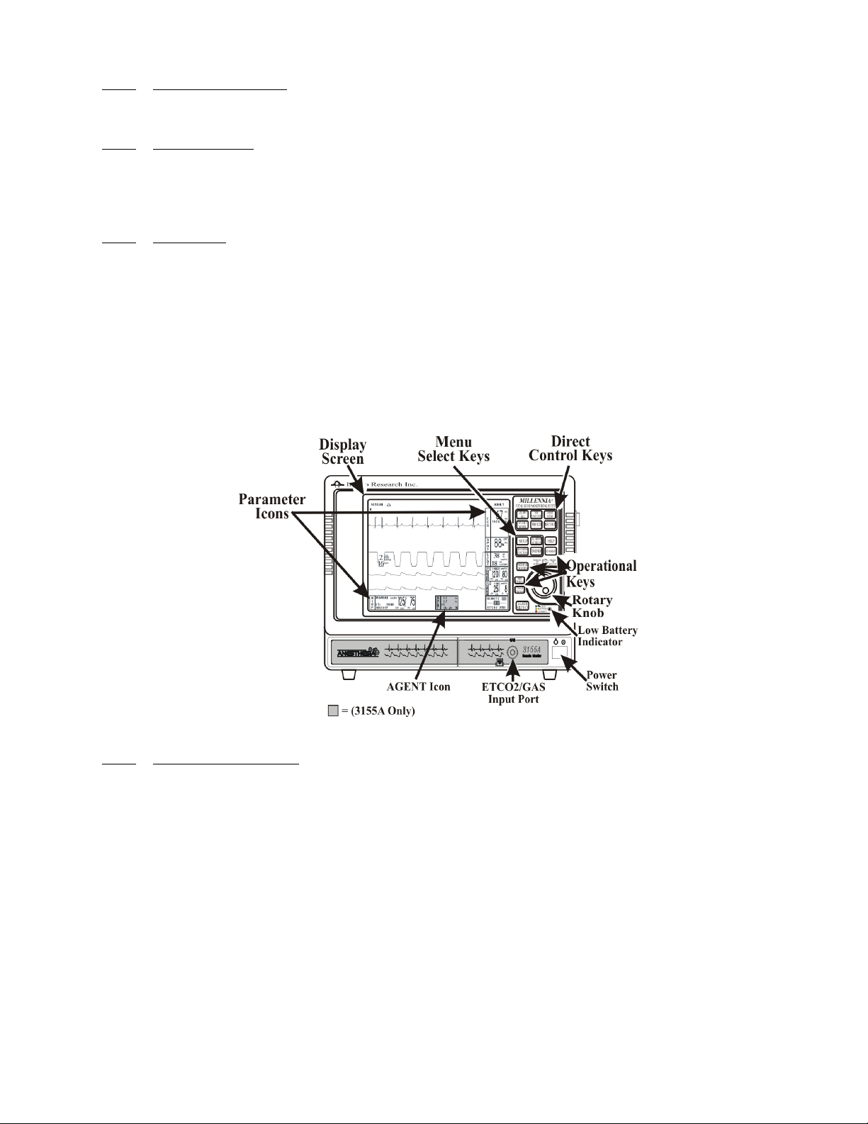
Figure 1-2. The Direct Control Keys
b. Direct Control Keys. (See Figure 1-2) There are six Direct Control keys: ZERO
ALL, NIBP START/STOP, NIBP STAT, EVENT MARK, FREEZE and
RECORD. These keys provide the operator with direct control of the following
features: Starting/Stopping NIBP Readings, Starting/Stopping the NIBP STAT Mode,
Freezing all Traces, Starting the Recorder, Adding a Marker to the Recorder and
Zeroing all Invasive Pressure Channels.
(1) ZERO ALL. (Item 1) The Pressure Transducer is zeroed by the 3150(M)
MRI Patient Monitor in the MRI Magnet Room, therefore this key is inactive
and pressing it will display a message to indicate that this function is not
available in the Remote Mode of Operation. See the 3150/ 3150M MRI Patient
Monitor Operation Manual (Part Number 9538) for further information.
(2) NIBP START/STOP. (Item 2) This key starts a new NIBP measurement, or
stops a measurement that is already in progress.
(3) NIBP STAT. (Item 3) This key starts the NIBP STAT Mode measurements.
This mode may be terminated by depressing the NIBP START/STOP key.
The STAT Mode performs up to five (5) NIBP measurements in rapid
succession (with a short pause between readings) within a maximum time
frame of five (5) minutes. This feature is not available with dual monitor
software (MPC01 or higher).
(4) EVENT MARK. (Item 4) The EVENT MARK key prints a marker on the
ECG Recorder Strip when the printer is running. If the printer is not running,
pressing this key has no effect.
1-3
(5) FREEZE. (Item 5) The 3155A/3155MVS Monitor freezes the ECG
waveform from Trace A for closer examination upon user demand. When the
ECG trace is active, pressing the FREEZE key will freeze it into the Trace B
location while Trace A remains active. When the trace is frozen, pressing the
FREEZE key will release it. A “Blue Box” appears around the frozen
waveform as a visual indication that the waveform is not active. While the
Freeze feature is active, the monitor will not allow any changes to the
Parameter Setups or Recall Setups; if the operator attempts to access the
PARAMETER SELECTION or RECALL SETUP menus, a WARNING Box
alerts the operator that entry to the selected menu is not allowed while
FREEZE is enabled.
(6) RECORD. (Item 6) Pressing this key records the Single Trace or Dual Trace
selections (as specified by operator adjustments made in the RECORDER
Menu). The recorder stops automatically after approximately 30 seconds, or
when the RECORD key is pressed again; in either case, the printout ends with
a “Snap Shot” of the active patient parameter data.
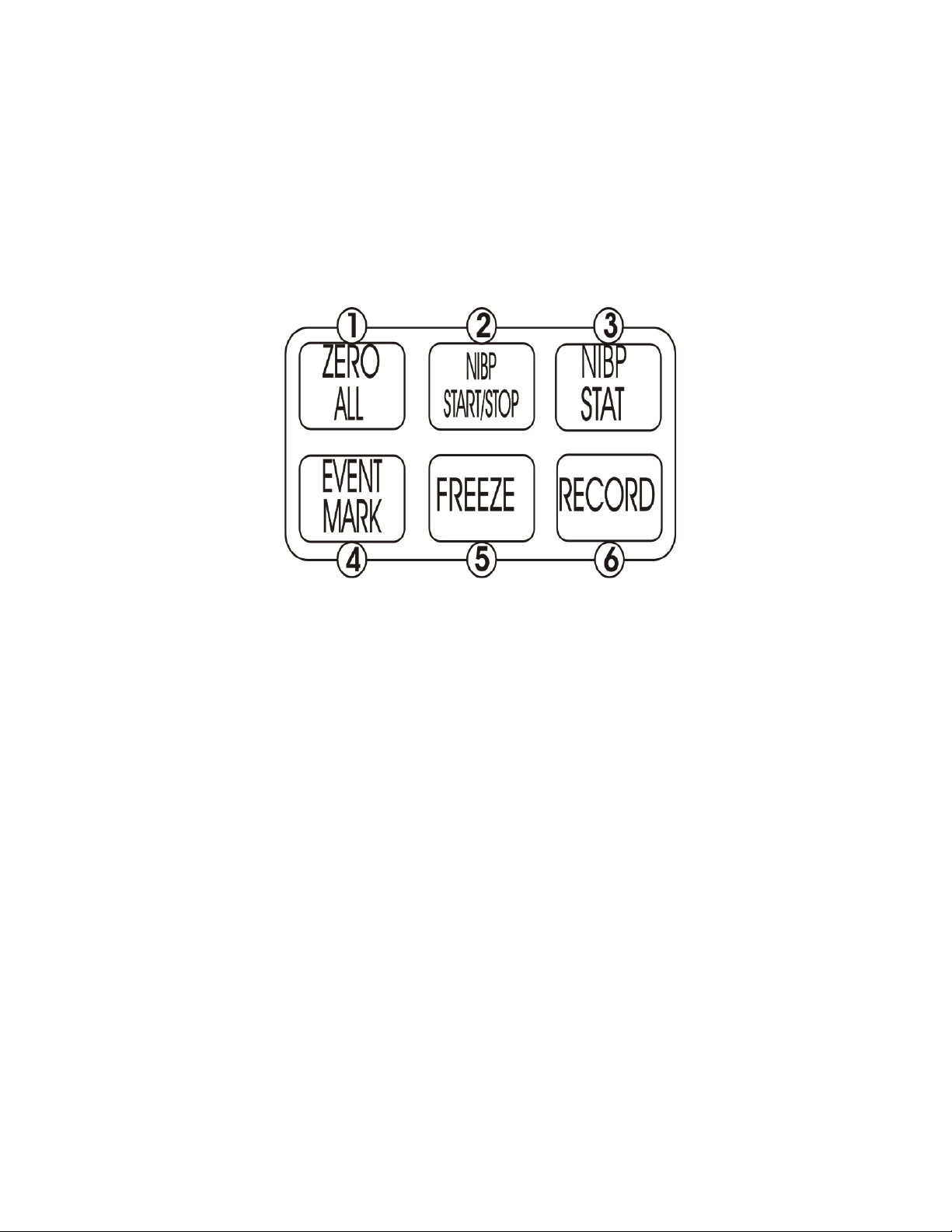
Figure 1-3. Menu-Select and Operation Keys
c. Menu-Select Keys. (See Figure 1-3) The Menu-Select keys allow the operator to
specialize the operation of the 3155A/3155MVS Monitor to suit specific procedures
and/or situations. Pressing a Menu-Select key will activate the “pop-up” menu for the
selected feature which is then controlled by the Rotary Knob so that the associated
parameters may be adjusted. The four Menu-Select keys are SETUP, ALARMS
SCREEN, RECORDER FUNCTIONS and TRENDS.
(1) SETUP. (Item 1) The SETUP key allows the operator to access the various
available setup options (See Section 3).
(2) ALARMS SCREEN. (Item 2) The ALARMS SCREEN key allows the
operator to setup the Alarms monitoring feature (See Section 6). If operating a
dual monitor system, with a 3155A and 3155MVS communicating with the
3150(M), the adjustments made here are interactive between the two 3155
monitors to ensure that the monitored parameters remain consistent between all
components of the MRI monitoring system.
1-4

(3) TRENDS. (Item 3) The TRENDS key allows the operator to setup the Trend
monitoring feature. The exact operation of the TRENDS key is based on
whether or not a feature is currently highlighted. If a feature is currently
highlighted, pressing the TRENDS key will bring up a Trend which is specific
to the highlighted feature; if a feature is not currently highlighted, pressing the
TRENDS key will bring up the HISTORY Menu and Tabular Display (See
Section 5).
(4) RECORDER FUNCTIONS. (Item 4) The RECORDER FUNCTIONS
key allows the operator to setup the Recorder option (See Section 5).
d. Operational Keys. (See Figure 1-3) The are five Operational keys: HELP,
STANDBY and NORMAL SCREEN.
(1) HELP. (Item 5) The HELP key is for future operational enhancement.
(2) STANDBY. (Item 6) Pressing the STANDBY key places the 3155A/
3155MVS Monitor into the Standby Mode. The monitor stays in Standby
Mode until the STANDBY key is pressed a second time. Except for the three
(3) key features given below, the monitor operates normally by continuing to
provide current patient information on the Display Screen. If operating a dual
monitor system, with a 3155A and 3155MVS communicating with the
3150(M), pressing this key will place both monitors into the Standby Mode.
While in Standby Mode:
• All audible alarms are disabled. The disabled alarms are indicated
on the screen by the “X” through the bell shaped Alarm Status
Symbol.
• Active NIBP automatic measurements are suspended.
• No automatic printout is generated.
(3) NORMAL SCREEN. (Item 7) Pressing the NORMAL SCREEN key
returns the 3155A/3155MVS Monitor from any menu to the normal screen.
(4) NIBP INTERVAL. Pressing the NIBP INTERVAL key brings up the NIBP
INTERVAL Menu where the cycle time (time between readings) of the NIBP
Automatic Reading Mode may be adjusted.
(5) CLEAR TRENDS. Pressing the CLEAR TRENDS key allows the operator
to clear all the stored data from memory. To prevent accidental erasure of
patient data, there is a Yes/No box associated with this key that appears to
ensure that the operator meant to clear the trend data. If operating a dual
monitor system, with a 3155A and 3155MVS communicating with the
3150(M), pressing this key will clear the trend file of both monitors.
e. Alarm Silence Key. Pressing the ALARM SILENCE key will silence any active
alarm. The letter “S” appears in the Alarm Bell and an “Alarm Silenced” message
appears in the center of the screen as visual indications that an alarm has been silenced.
If operating a dual monitor system, with a 3155A and 3155MVS communicating with
the 3150(M), the ALARM SILENCE key is interactive throughout the MRI
monitoring system. The details of this key's function depend on the monitor's settings:
(1) Unlatched Alarms. If the alarm system has been set to UNLATCHED in the
ALARMS Menu and an Alarm Limit is violated, pressing the ALARM
SILENCE key will silence the Alarm Tone when an active Alarm Limit has
been violated. While the parameter continues to violate its limits, the numerics
of the violating parameter continue to flash on the screen. If operating a dual
monitor system, with a 3155A and 3155MVS communicating with the
3150(M), the adjustments made here are interactive between the two 3155
monitors to ensure that the monitored parameters remain consistent between all
components of the MRI monitoring system.
1-5

(2) Latched Alarms. If the alarm system has been set to LATCHED in the
ALARMS Menu and an Alarm Limit is violated, while the parameter
continues to violate its limits, pressing ALARM SILENCE key stops the
Alarm Tone, but the numerics remain red and continue to flash, even after the
parameter returns to within its Alarm Limits. If operating a dual monitor
system, with a 3155A and 3155MVS communicating with the 3150(M), the
adjustments made here are interactive between the two 3155 monitors to
ensure that the monitored parameters remain consistent between all
components of the MRI monitoring system.
(3) ALARM HOLD. If the ALARM SILENCE key is pressed when the Alarm
Tone is enabled but no alarm condition currently exists, a “SOUND ON
HOLD” message appears in the upper center of the screen with a count down
timer starting at 180 (counting down at a 1 second rate) denoting that the
Alarm Tone is being temporarily held silent. In addition, an “H” will appear in
the Alarm Status Symbol to further alert the operator that the Alarm System is
on Hold.
If the Alarm Tone is sounding, the first pressing of the ALARM SILENCE
key stops the Alarm Tone and puts the letter “S” in the Alarm Bell, and a
second pressing enables Alarm Hold.
The monitor automatically exits alarm hold after three minutes, and the
“SOUND ON HOLD” message disappears from the screen, reactivating the
Alarm Tone. Pressing the ALARM SILENCE key before the three minute
period is over will also reactivate the Alarm Tone and remove the “SOUND
ON HOLD” message from the screen.
The user is able to put alarms on hold (SOUND ON HOLD) only when the
Alarm Tone is active (no X appears in the bell symbol in the upper left of the
screen). Alarm Hold is useful for temporarily disabling the Alarm Tone. This
might be useful, for example, when changing ECG leads, when drawing blood
from an arterial pressure line, or for any user activity which might cause a
“false” alarm.
f. ETCO2/Gas Input Port. (3155A only) Located on the bottom of the monitor front
panel, the ETCO2 Input Port is for the connection of the ETCO2 or Gas connector.
g. Low Battery Indicator. The Low Battery Indicator (located beneath the Rotary Knob)
is a three color LED that indicates the DC/Battery Power condition of the monitor. The
Power Light will illuminate Green, Yellow and Red as described below:
(1) Green Light. A Green Light indicates that the monitor is operating on DC
Power from the AS153 AC Power Adapter. In normal operation, this light will
be illuminated Green.
(2) Yellow Light. A Yellow Light indicates Caution because the monitor is
operating on the internal batteries. The internal batteries are intended for
temporary use only (such as during patient transport or brief outages of facility
power) with an operating time dependent on the number of batteries your
monitor has.
(3) Red Light. A Red Light indicates Warning because monitor shutdown is soon
to occur. The internal batteries have fallen below the required operational
output and an AC Wall Outlet should be located, and the monitor plugged into
it through the AS153 AC Power Adapter, immediately.
h. ETCO2 Waste Gas Exhaust. (3155A only) Located on the monitor back panel, the
ETCO2 Waste Gas Exhaust Port is used for release of waste gas from the optional
ETCO2 module and, when equipped with the Anesthetic Agent option, provides for
the connection of the O2 Sensor (Invivo Research, Inc. Part Number 9445). This port is
constructed to allow for connection into any existing Gas Scavenge system.
1-6
i. Power Switch. The Power Switch allows the operator to apply and remove power
from the 3155A/3155MVS Monitor.
1.2.2
optional Recorder Unit.
The Side Panel. The Side Panel contains the I/O Port for the PCMCIA “Flash” Card and the
a. PCMCIA I/O Port. The PCMCIA I/O Port allows for reloading of the monitor
software and also for monitor upgrade.
b. Recorder Unit. The Recorder provides a printout of patient parameter data either
automatically or upon operator demand.
c. Batteries. To install the monitor batteries, turn the retainer screw on the side panel to
open the door then push the battery into the slot until it snaps into place. To remove the
batteries, turn the retainer screw on the side panel to open the door then push the
battery clip away from the battery and pull the battery out of the slot.
Figure 1-4. The Back Panel
1.2.3 Back Panel Connections and Inputs. (See Figure 1-4) The following is a description of the
Back Panel Connections and Inputs:
a. RF ANTENNA. (Item 1) The antenna that receives the information from the 3150(M)
monitor.
b. GAS ZERO. (Item 2) (3155A only) The GAS ZERO Port is used for zeroing of the
optional ETCO2 and/or Anesthetic Agent Gas module.
c. DC POWER FUSE. (Item 3) The DC Power Fuse protects the monitor from surges
in DC Power.
d. WASTE GAS EXHAUST. (Item 4) (3155A only) The Waste Gas Exhaust Port is
used for release of waste gas from the optional ETCO2 module and, when equipped
with the Anesthetic Agent option, provides for the connection of the O2 Sensor (Invivo
Research, Inc. Part Number 9445). This port is constructed to allow for connection into
any existing Gas Scavenge system.
e. DC Power Connection. (Item 5) The DC Power Connection is where the AS153 AC
Power Adapter is connected to this monitor.
1.3 Display. The 3155A/3155MVS Monitor display screen (See Figure 1-5) displays three
groups of data: 1) the Informational Display, 2) the Vital Signs Trace Display and 3) the Vital Signs
Numeric Display. The entire display screen, with its three different display groups, is called the
“Normal Screen.” The three displays are described below.
1-7
Figure 1-5. The Normal Screen
1.3.1
the Normal Display. This display provides the operator with the current time, the Alarm Status Bell
Symbol, a flashing Heart Rate Symbol, a flashing Lung Symbol, any current user messages and the
current Patient Selection.
Informational Display. (See Figure 1-6) The Informational Display is located at the top of
Figure 1-6. The Informational Display
a. Time. The current time is displayed in a 12 or 24 hour format (hh:mm:ss). The time,
date and clock mode (12 or 24 hour) is adjusted in the TIME Menu.
b. Alarm Status Symbol. The 3155A/3155MVS Monitor sounds an Alarm Tone when
any monitored parameter violates its programmed Alarm Limits. The status of the
Alarm Tone is indicated by the bell shaped Alarm Status Symbol.
WARNING
When an “X” appears in the Alarm Status Symbol, the audible Alarm Tone will NOT sound for any
reason.
(1) The letter “H” appearing in the bell indicates that the alarms have been placed
on temporary Hold with the ALARM SILENCE key. Similarly, during
power-up the “SOUND ON HOLD” message displayed in the center of the
screen indicates that the Alarm Tone is temporarily placed on hold. A 180
second countdown timer is also displayed under the message.
(2) The letter “X” appearing in the bell symbol indicates that the alarms have been
turned off from the ALARMS Menu or that Standby Mode has been engaged.
In this case the Alarm Tone will not sound for any reason.
1-8
(3) The letter “S” appearing in the bell indicates that a current alarm has been
silenced with the ALARM SILENCE key. This feature will disable only the
alarms that were current when the ALARM SILENCE key was pressed, any
new alarms will cause the Alarm Tone to sound.
c. Heart Symbol. The Heart Symbol flashes on the screen each time a heart beat is
detected. A tone is sounded at the same time (unless turned off in the ECG Menu or
the SPO2 Menu).
d. Messages. These messages assist the operator in various aspects of the operation of
this monitor.
e. Patient Selection. Indicates the selected patient (ADULT or NEONATAL) for the
ECG, ETCO2 and NIBP monitoring features. If operating a dual monitor system, with
a 3155A and 3155MVS communicating with the 3150(M), the adjustments made here
are interactive between the two 3155 monitors to ensure that the monitored parameters
remain consistent between all components of the MRI monitoring system.
Figure 1-7. The Middle Screen Vital Signs Trace Display
1.3.2
middle of the Display Screen. This Display provides the operator with a trace of the selected
parameters and also contains Numerical Vital Sign indications for the selected patient parameter.
Vital Signs Trace Display. (See Figure 1-7) The Vital Signs Trace Display is located in the
a. The Vital Signs Trace Display portion of the screen is divided into six separate trace
areas. When turned on, the traces (A through E) are fixed on the screen and updated
with an Erase Bar. When a trace has been turned off, that portion of the screen is blank.
The numeric values for each trace appear near the right screen boundary.
b. If the value is greater than or equal to a maximum calculable value, “OVR” (Over
Range) is alternately displayed with the numeric value.
The following is a description of each Trace:
c. TRACE A. The ECG 1 trace is displayed in this position, unless turned off from either
the ECG Menu or the SETUPS Menu. The main menu for this trace and for the Heart
Rate are brought up with the selection of the ECG Menu-Select Icon. If operating a
dual monitor system, with a 3155A and 3155MVS communicating with the 3150(M),
the adjustments made here are interactive between the two 3155 monitors to ensure
that the monitored parameters remain consistent between all components of the MRI
monitoring system.
(1) The heart rate is displayed near the right screen boundary in the Trace A
position. The numerics turn Red and flash if a Heart Rate Alarm Limit is
violated. The color of the numerics is that of the selected HR source.
1-9

(2) The annotation below the heart rate value indicates the source of the heart rate,
as selected from the ECG Menu, the NIBP Menu, the P1 or P2 Menus or the
SPO2 Menu. Heart rate source choices are AUTO, ECG, ART (P1 or P2),
SPO2 and NIBP.
(3) A red flashing numeric value on the screen indicates that an alarm for this
value has been violated. This provides a visual indication of alarm violations,
even when the Alarm Tone is turned off.
(4) If AUTO is selected as the HR SOURCE, the highest-priority active input is
utilized for displaying the heart rate, in the following order: ECG, P1, P2,
SpO2 and NIBP. The ECG trace must be off, or lead fail present, for the Auto
heart rate source not to be the ECG trace.
(5) If the monitor does not find a valid heart rate source when set to AUTO and
NIBP is OFF, the heart rate is annotated with “NONE.”
(6) The displayed lead for the ECG is indicated near the left screen boundary.
(7) A scale indicator is displayed near the left screen boundary in the ECG
waveform area(s). It represents a 1mV amplitude in the currently selected
scale.
d. TRACE B. The SpO2 waveform is displayed in this trace location unless it is turned
off in the SETUPS Menu or P2 is ON. If operating a dual monitor system, with a
3155A and 3155MVS communicating with the 3150(M), the adjustments made here
are interactive between the two 3155 monitors to ensure that the monitored parameters
remain consistent between all components of the MRI monitoring system.
e. TRACE C. The ETCO2 waveform is displayed in this trace location unless it is turned
off in the SETUPS Menu. If operating a dual monitor system, with a 3155A and
3155MVS communicating with the 3150(M), the adjustments made here are
interactive between the two 3155 monitors to ensure that the monitored parameters
remain consistent between all components of the MRI monitoring system.
f. TRACE D. The P1 waveform is displayed in this trace location unless it is turned off
from the SETUPS Menu. If operating a dual monitor system, with a 3155A and
3155MVS communicating with the 3150(M), the adjustments made here are
interactive between the two 3155 monitors to ensure that the monitored parameters
remain consistent between all components of the MRI monitoring system.
g. TRACE E. The P2 waveform is displayed in this trace location unless it is turned off
from the SETUPS Menu. If operating a dual monitor system, with a 3155A and
3155MVS communicating with the 3150(M), the adjustments made here are
interactive between the two 3155 monitors to ensure that the monitored parameters
remain consistent between all components of the MRI monitoring system.
Figure 1-8. The Bottom Vital Signs Numeric Display
1.3.3
Displays are located at the bottom of the display screen with the NIBP Icon located to the left, the
Agents Icon in the center and Remote to the right. While not in “dual monitor” mode and using a
3155MVS alone, the Agents Icon will not be available for display. This Display is divided with boxes
that provide the operator with numerical indications of the NIBP, Agents and a visual indication that
the monitor is in the Remote Operation Mode along with the source of ETCO2 (3155 or 3150).
NIBP, Agents and Remote Display. (See Figure 1-8) The NIBP, Agents and Remote
1-10

The following is a description of the possible selections for the Vital Signs Display:
a. Non-Invasive Blood Pressure (NIBP). NIBP is displayed on the bottom left of the
display screen. The Systolic, Diastolic and Mean blood pressure values are displayed
along with measurement information such as the Elapsed Time (ET) since the last
measurement and the time until the next measurement (if in the Automatic Mode).
While in the Manual mode, MANUAL is shown in the place of the time until the next
measurement.
The NIBP error messages are shown in place of the “NEXT: 00:00:00.” If errors are
detected by the NIBP circuitry, one of the following messages are displayed which
preclude the determination of the blood pressure (if operating a dual monitor system,
these messages are interactive throughout the MRI monitoring system):
(1) OVR-PRES: Cuff inflation pressure has exceeded 270 ±5 mmHg.
(2) CALIB: The monitor cannot zero the pressure transducer.
(3) HDW-FAIL: The NIBP electronic or pneumatic circuitry has failed.
(4) LONG PRESS: The monitor has taken more than three minutes to make a
Blood Pressure determination or cuff inflation runs longer than 30 seconds.
During a reading cycle the current cuff pressure is displayed (“CUFF: XXX”).
Between the measurements the elapsed time (time since the last reading) is displayed
(ET= 00:00:00) instead of the cuff pressure.
b. Anesthetic Agents. (“Dual monitor” mode or 3155A only) The Agents Icon is located
between the Remote Status and NIBP boxes depending upon the screen display; if P1
and P2 and both off the Agents box is located right next to the Remote Status box and
if either P1 or P2 is on then the box is centered between the Remote Status and NIBP
boxes.
The Agents Icon box displays the identification of the gas being monitored, the
inspired and expired gas value numerics and the Oxygen value numerics.
c. Remote Status. The Remote Status box is located on the bottom right of the display
screen to indicate that the monitor is in Remote Communication Status. The connectors
in the center of the Icon box will disconnect whenever there is a communication loss
from the 3150(M) MRI Patient Monitor greater than three seconds. The Remote
Status box is green whenever communication with the 3150(M) MRI Patient
Monitor is good and red whenever communication is lost at any time (which provides
a visual indication of all communication losses of less than three seconds).
If operating a dual monitor system, or using a 3155A alone, the bottom of the Remote
Status box is an indication of the ETCO2 source. When ETCO2 is derived from the
3155A/3155MVS Monitor this message area will indicate “ETCO2 3155,” when
ETCO2 is derived from the 3150(M) this message area will indicate “ETCO2 3150,”
and when ETCO2 is Off on both monitors, or when using the 3155MVS alone, this
message area is blank.
1.4 Yes/No Menu. In various menus, the operator may accidentally make a selection that has
significant irreversible effects (e.g.: erasing patient data). To protect against such accidents a Ye s / N o
Menu is associated with these selections. When one of these selections is made, the Ye s / N o Menu is
displayed in the center of the display screen. This menu has only two active selections: YES and NO.
The operator must select one of the two choices to either confirm the change to take place, or to cancel
it. A delay of approximately 30 seconds without any selection is equivalent to selecting NO. The Ye s /
No Menu is removed upon operator selection or at the end of the time-out feature.
1.5 Cleaning. The monitor is not sterilizable. Never immerse the unit in any fluid or attempt to
clean it with liquid cleaning agents. Remove dirt and dust from the monitor by wiping it with a soft,
damp cloth.
1-11

Stains can be removed from the case by scrubbing it briskly with a damp cloth. Unplug the
monitor and remove the batteries before cleaning. Do not permit liquid to contact the front or rear
of the monitor, or permit liquid to drip into the printer or cooling slots. Allow the unit to dry
completely before returning it to operation.
WARNING
Electrical shock hazard: Turn off Monitor and disconnect from the AS153 AC Power Adapter
before cleaning. Do not immerse the monitor in any water or liquid for any reason. Do not apply
excessive pressure to the monitor display screen.
1.5.1
Disposable patient accessories should be discarded and replaced with new items.
To clean reusable accessories, first, remove the accessory from the monitor. Remove any dirt or
debris using soap and water. Avoid immersing accessory in any fluid for cleaning.
Inspect the accessory for any cracks, holes, tears, cuts, etc., that could affect operation, and replace as
necessary.
If disinfection is required, use only the recommended liquid surface disinfectants, unless otherwise
specified in the accessories listing. Recommended surface disinfectants include dilute solutions of
either quaternary ammonium compounds, iodophors or gluteraldehydes.
Cleaning Accessories. Any reusable patient accessories should be cleaned after each use.
1-12
 Loading...