

Invicta DI-32 Operator's Manual
OPERATORS MANUAL
JOINTER
by
INVICTA
Model
DI-32
INVICTA USA English Version
(8
77) 308-6423 – East
Revision Nº 1
(800) 499-4682 - West

JOINTER
Model DI-32
General Instructions
As with all equipment, safety is to be a priority. The operator should understand the safety features and apply good
safety habits in transportation, adjustment, maintenance and operation of the machine. Practice and teach others
the safe operating procedures of this machine and help to prevent the possibility of accidents.
Safety Rules
1. For your own safety, read carefully the Instruction Manual before attempting to operate the machine.
2. If you are not thoroughly familiar and comfortable with the adjustment and operation of the machine, ask for
instruction from your supervisor or a fully qualified person. You may also contact Invicta USA.
3. Before the initial operation of the machine, remove all packaging, shipping grease and fully assemble the
machine. Pay special attention to the assembly of safety components.
4. Wear proper apparel while operating the machine. Never wear loose fitting clothing, gloves or ties. Always
remove rings or other jewelry before operating the machine. It is strongly suggested the operator wear
shoes with non-slip soles and also wear a protective hair net to prevent hair entanglement in moving parts.
5. Always wear personal safety equipment. Follow the safety regulations of your country and your company.
6. Have a certified person make all wiring connections to power source and properly gro und the machine.
7. Always disconnect the machine from the power source and use lockout procedures before servicing,
changing cutting tools and during any cleaning of the machine.
8. Before starting the machine, be aware that the work area is clean and free of debris. Cluttered areas are
invitations for accidents to occur. .
9. Keep the safety guard(s) of the machine in place and in proper working condition. Never operate
machinery without safety equipment in place. Report any damage to your supervisor.
10. Keep children and visitors a safe distance from the working area.
11. Never leave the machine running while unattended. Turn off the power source during breaks. The machine
should come to a complete stop before walking away.
12. Do not operate the machine under the influence of drugs or alcohol. Consult your physician when taking
medications.
13. Do not force the machine beyond its limitations. It will produce a nicer and safer job and at the rate it was
designed to operate.
Additional Safety Rules for the Operation of Jointers
1) Avoid Kickbacks. “Kickback” can occur when the workpiece is forced back by the cutter during improper
operation. When “Kickback” occurs an injury can result. Some of the causes of Kickback are:
A- Dull and Improperly Adjusted Knives.
B- Knots, Nails or Imperfections in the workpiece.
C- Heavier Cuts than the machine was designed for.
D- Failure to use a pusher block when jointing or planing short, thin or narrow workpieces.
2) Always maintain the proper relationship of in-feed and out-feed table surfaces to the cutterhead.
3) Never start the work-piece into the cutterhead before allowing it to reach operation speed.
4) Keep the Knives sharp and free of rust and pitch
5) Never perform jointing or planing cuts deeper than l/8” (3 mm).
6) Support and control the workpiece properly all times during the operation.
7) Never reverse the direction of the workpiece after beginning operation. Kickback can occur.
8) Definitions of jointing and planing operations:
A- Jointing operations: The workpiece is positioned on the jointer with the narrow edge of work piece on the
in-feed table and the larger surface positioned against the fence. The workpiece is moved right to left from
the in-feed table across the cutterhead to the out-feed table.
B- Planing operations: Planing is a similar operation to the jointing operation except for the position of the
work piece. For planing, the larger flat surface of workpiece is placed on the infeed table of the jointer and
the narrow edge of the workpiece positioned against the fence.
01
JOINTER
Mod. DI-32
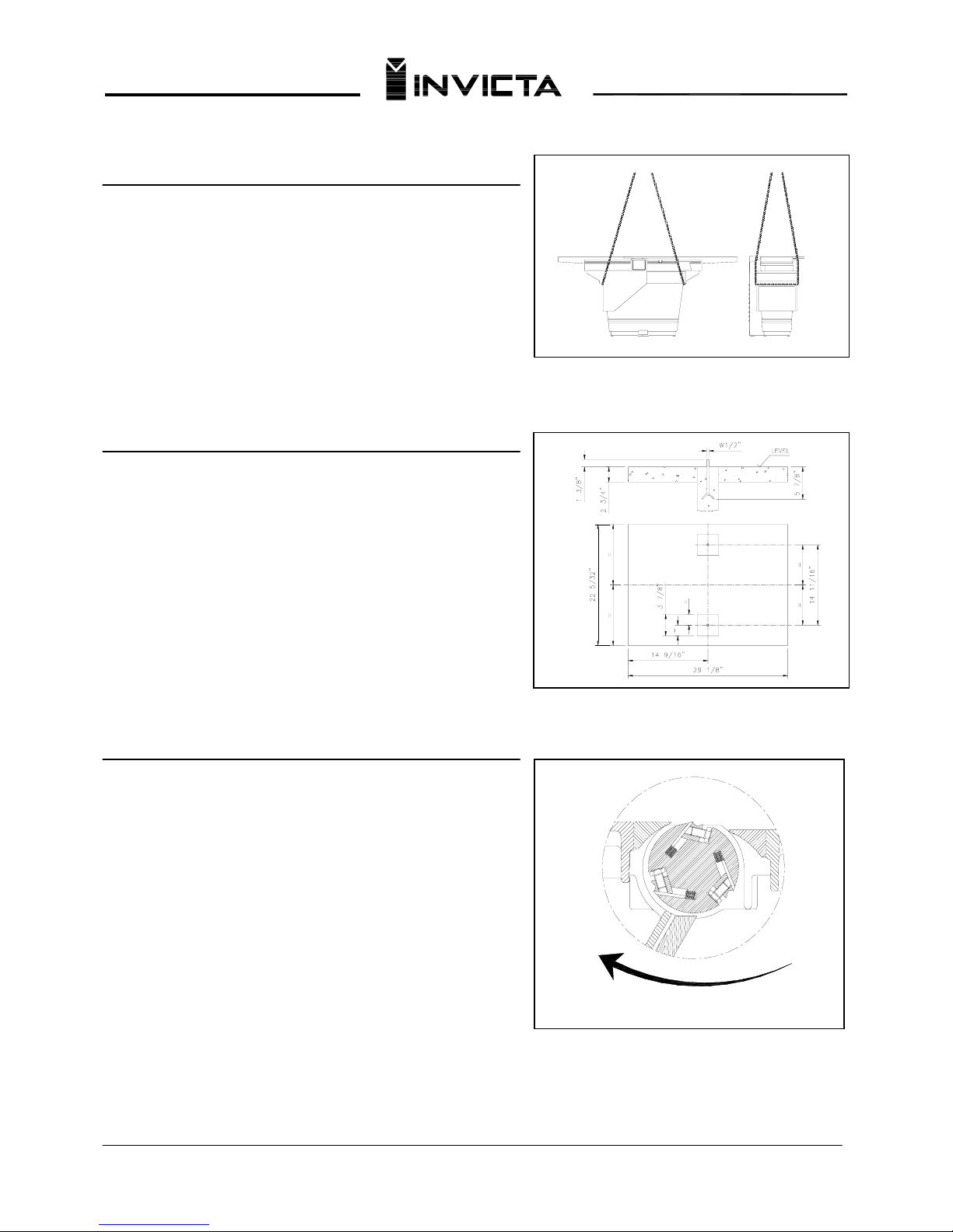
Loading and Unloading
Never load or unload the machine by the In-feed or Out-feed
tables because damage can occur. Lift the machine by straps
placed in areas shown in (Fig.01)
Fig.01
Installing the Machine
Level the machine on a solid surface to avoid vibration. See the
foundation sketch in (Fig.02)
Fig.02
Connecting the Machine to the Power Source
Each machine is provided with a reference plate that indicates
the requirements for electrical service needed for the machine to
operate property. Before you call a certified electrician to make
the wiring connections, be sure that the voltage and cycle
(phase) stated on this reference plate are the same as provided
in your building.
(Electrician) Remove the electrical box cover and connect the
electrical supply wires to the proper terminals. Rapidly turn on
and off the machine, then visibly check the rotation direction of
the cutterhead. It should correspond to the direction indicated on
(figure 03.) If not, procceed with the instructions below:
For three-phase machines: invert two wires of the power source
without changing the internal connections of the machine. See
the electrical diagrams for three-phase on page 06 if further
information is needed or contact Invicta USA.
CUTTERHEAD ROTATION DIRECTION
Fig.03
0
2

JOINTER
Mod. DI-32
Technical Specifications
In-feed Table…………………………………………………………………………..…………………………… ………....42”
Out-feed Table…………………………………………………………………….……………………..…………………....42”
Max Width Capacity………………………………………………………………………………………….…………...12 5/8”
Cutterhead Speed……………………………………………………………………… ………………………..…..4375 RPM
Maximum Cutting Depth…………………………………………………………………………… …………..……………3/4”
Fence Tilting.....................................................................................................................................................0º to 45º
Motor Power………………………………………………………..3 HP (230v/1ph), 5 HP (230v/3ph) or 5 HP (460v/3ph)
Net Weight………………………………………………………………………………… ……………………………..838 Lbs
Accessories
Normal Accessories Optional Accessories
1. Instructions Manual 1. Knife gauge
2. Tool Kit
Adjustment Instructions
Cutting Depth Adjustment
The quantity of material to be removed can be from 0” (0 mm) to 3/4” (19 mm) on the infeed table. To adjust the
cutting depth, raise or lower the infeed table by loosening lock “G” and moving lever “E” (figure 06) on page 04.
Cutter Adjustment
For the best perfomance of the machine, the knives must be completely
aligned parallel with the surface of the outfeed table. The outfeed table
should be adjusted no more than 3/64” (1 mm) above the cutterhead
surface. (Never allow the outfeed table surface to drop below Top Dead
Center of the cutterhead) The outfeed table can be adjusted by
loosening the handle “F” (M) and moving the lever “D”. (Figure 6 & 7)
Adjustment of the Knives: (disconnect power supply)
Hold a straight edge firm against the outfeed table and across the
cutterhead. Rotate the cutterhead with knife installed. If straight edge
touches the knife raise the outfeed table and repeat the process until
the knife passes the straight edge without touching. (Lock outfeed table
in place) Check each side of cutterhead starting at the fence and then at
the operator side. If one side touches and the other does not, the knife is not yet parallel.
Continue to adjust knife until perfection is achieved. Securely tighten all screws “A” once final adjustment is made.
Follow the same procedure to adjust the other knives remembering to tighten the screws “A” (Figure 04)
STRAIGHT EDGE
A
Fig.04
IMPORTANT: The knives must be in the same relation to the straight edge when each knife is Top Dead Center.
No lifting of the straight edge should be noticed. The outfeed table is also in its best position. Remember to
securely lock the outfeed table.
0
3
JOINTER
Mod. DI-32
Adjustment Instructions
Fence Adjustment
The fence can be adjusted in two
different ways:
1. For the angular adjustment loosen the
lock “C” and tilt the fence to desired
position. Re-Lock handle “C”.
2. Adjust the cross movement of the
fence in relation to the tables by
loosening lock “B” sliding the fence to the
desired position. Re-Lock handle “B”.
(Fig. 05)
B
C
Fig.05
Maintenance
Belts tension and replacement
Remove the belt guard to access the belt. Loosen locking nuts “J & L” and lift motor to remove belt or press down
on the motor to obtain an adequate tension. Re-Lock nuts “J & L”. (Figure 06)
H
D
I
F
J
L
G
E
Fig.06
0
4
 Loading...