

Page 1
SOLAR WATER PUMP
DC CONTROLLER
User Manual
inverter.com
Email: sales@inverter.com
Web: https://www.inverter.com/
Tel: +1 800-585-1519 (Toll-free)
Page 2

1. The DC controller will be burned out when the open-circuit voltage is higher than setting
value.
2. The DC controller must match with the recommended solar pumps.
3. Do not use the DC controller for other pumps. If cause any problems because of this
reason. We do not bare any responsibility.
4. For the perfect performance and long-life working, the DC controller should be kept
away from strike, shake, sunshine, salt mist, oil mist and etc.
5. Because of the power loss from cable, try to use the shortest cable.
6. While use longer cable, the cable connecting DC controller and solar panels should be
over 4mm2 (Do not use single wire type). While the cable between DC controller and
pump within 30m, the cable should be at least 2mm2. While over 30m, the cable should
be at least 4mm2.
Page 3

CONTENTS
1. Overview .................................................................................................... 1
2. Specification .............................................................................................. 1
3. Installation and Wiring .............................................................................. 2
3.1 Solar Panel Selection ............................................................................................... 2
3.2 Solar Water Pumping System Installation Diagram .............................................. 4
3.3 Solar DC Controller Wiring Diagram ....................................................................... 4
3.4 Wiring Instructions ................................................................................................... 5
4. Operation ................................................................................................... 5
4.1 Operation Panel ........................................................................................................ 5
4.2 Key Instructions ....................................................................................................... 6
4.3 Test Running............................................................................................................. 6
4.4 Operation Mode ........................................................................................................ 7
5. Servicing and Maintenance ...................................................................... 9
6. Fault Analysis and Corresponding Solutions ......................................... 9
Page 4
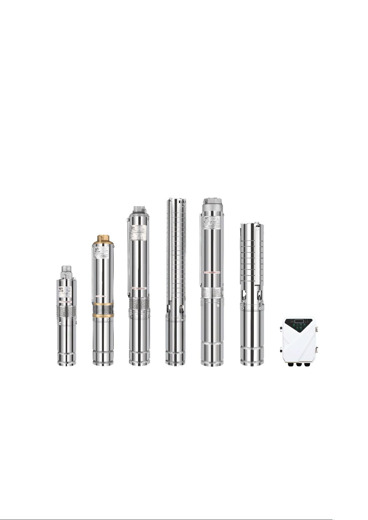
1. Overview
Controller and Pump Matching Method
Controller
Model
Adaptable
Pump
Max. Input
Current (A)
Max. Open
Voltage (V)
MPPT
Voltage
Range (V)
Working
Temperature
(℃)
DF-12
Rated 12V
Pump
15
<48
30-48
-15~+60
DF-24
Rated 24V
Pump
15
<48
30-48
-15~+60
DF-36
Rated 36V
Pump
15
<48
30-48
-15~+60
DF-48
Rated 48V
Pump
15
<100
60-90
-15~+60
DF-72
Rated 72V
Pump
15
<150
90-120
-15~+60
DF-110
Rated 110V
Pump
15
<200
110-150
-15~+60
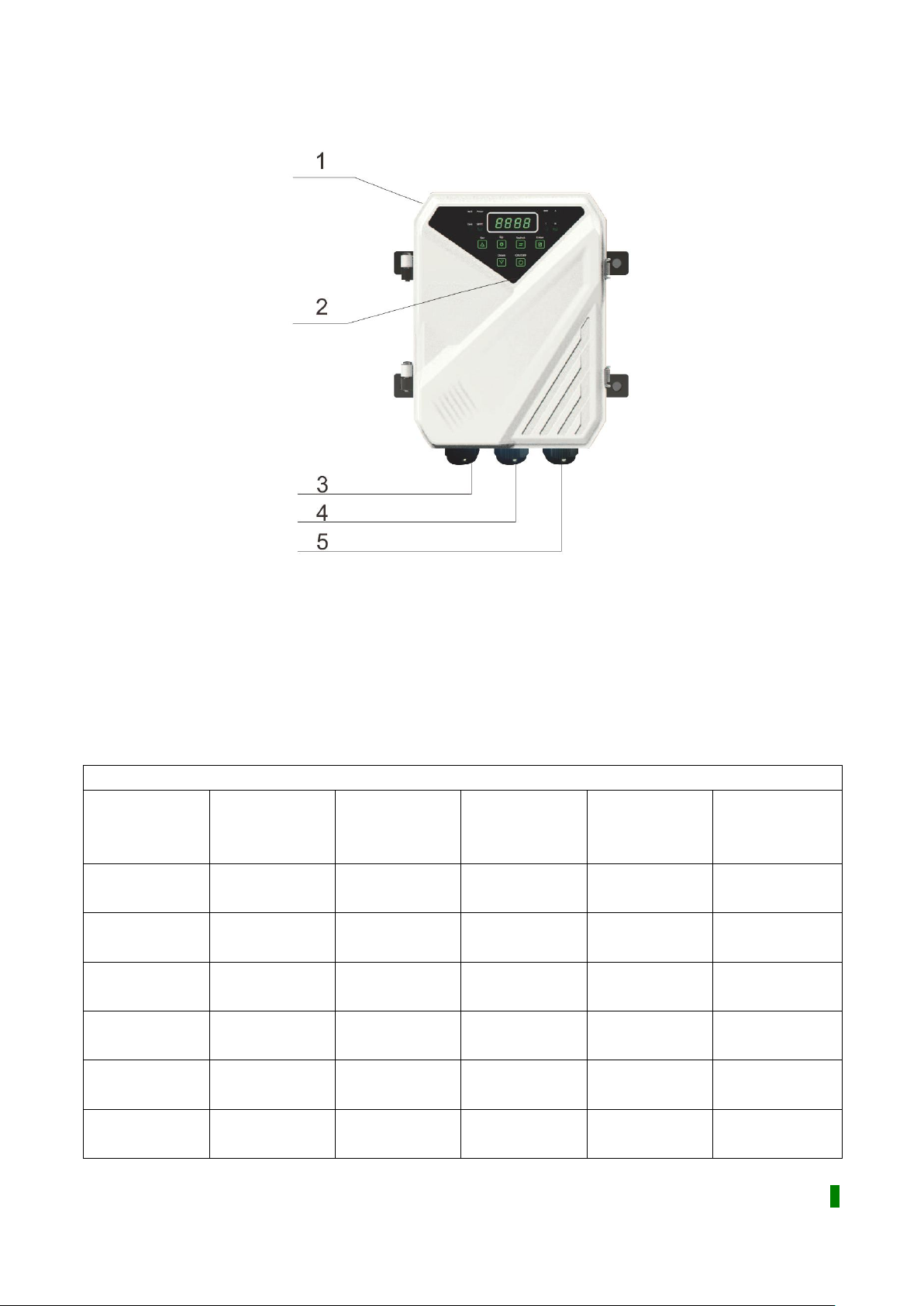
1. Nameplate and caution
2. Operation panel
3. DC electric cable entrance
4. Water level sensor cable entrance
5. Pump electric cable entrance
2. Specification
Working Environment and Electrical Property
1
Page 5

3. Installation and Wiring
3.1 Solar Panel Selection
Before installing the solar water pump and DC controller, we should know how to select the
solar panel for the solar water pumping system.
3.1.1 Select the type
Solar panel can be divided into thin-film photocell, polycrystalline silicon solar cell and
mono-crystalline silicon solar cell. The prices are different for the three kinds of solar panel.
Mono-crystalline type has the highest price but the efficient is the best. The thin-film
photocell is the cheapest one.
3.1.2 Select the rated power and Voc
Rated power: The power is proportional to the panel area. Normally, the rated power
of solar cell is 150W per square meter.
Voc: The open-circuit voltage (Voc) means the max electromotive force before solar
panel working. The common open-circuit voltage (Voc) is DC 21V, 36V, 44V, etc. The
lower the temperature, the higher the Voc. Because the open-circuit voltage changes
along with the change of area and temperature. If the Voc is not high enough, connect
more solar cells in series. The total voltage value equals the sum of each panel's Voc.
How to select Voc and rated power?
When solar panel working, its voltage will decrease, this voltage is called working
voltage (Vmp). The Vmp of solar cell needs to be selected according to the solar
pump controller's working voltage, and then to confirm the open-circuit voltage (Voc)
of solar panel.
After that, according to the solar pump power to select the solar panel power. The
generating efficiency of solar panel is under 70% usually. In order to ensure the rated
working time (for example 4 hours a day), the solar panel power equals to 1.5 times of
solar pump power. It is the minimum power for choose. That means, if the solar panel
power is smaller than the minimum power, the solar pump can work normally but can't
reach its rated flow and head. The best solution is to use more solar panels if
condition permits, and it is also ensure more working time for the solar water pump.
3.1.3 Solar panel recommendation for 12V-110V DC solar water pump
When the solar panels are in series connection, the voltage is added, but the current isn't
changed.
When the solar panels are in parallel connection, the voltage is unchanged, but the current is
added.
Before the power is on, you must use the instrument to detect the open circuit voltage of
solar panels, or apply for series, parallel knowledge to calculate the solar panel open circuit
voltage. The open-circuit voltage of solar array must be less than the maximum input voltage
2
Page 6

of the controller, otherwise is will cause irreversible damage.
150W
Max power: 150W
Short Circuit Current: 9A
Open Circuit Voltage: 22V
Max Power Current: 8.4A
Max Power Voltage: 18V
265W
Max power: 265W
Short Circuit Current: 8.7A
Open Circuit Voltage: 36.6V
Max Power Current: 7.68A
Max Power Voltage: 30.6V
340W
Max power: 340W
Short Circuit Current: 9.5A
Open Circuit Voltage: 46.2V
Max Power Current: 8.9A
Max Power Voltage: 38.2V
Solar Panel Specification:
3
Page 7

3.2 Solar Water Pumping System Installation Diagram
3.3 Solar DC Controller Wiring Diagram
4
Page 8

3.4 Wiring Instructions
Before you star wiring the controller box switch MUST be in the OFF position. Wire the solar
pump and solar panels to the DC controller as per the wiring diagram. Make sure the pump
and controller are not touching each other. If the wiring is incorrect, the pump will run
backwards. Then exchange two wires of solar panel to the correct wiring. When connecting
with the battery, make sure the polarity is correct, "+" to "+", "-" to "-".
Caution:
1. When wiring a battery. Be careful not to reverse or short the terminals. We advise you
remove all metal wrist bands or watches before you start.
2. Solar PV panels connecting together can also produce a lot of energy. So operators are
more careful about wiring.
3. A dark cloth to shade the panels is good precaution to reduce the power output.
4. Operation
4.1 Operation Panel
Voltage (V): Voltage indicator lights.
Speed (RPM): Speed indicator light.
Current (A): Current indicator light.
Power (W): Power indicator light.
Tank: Light when tank is filled with water.
Well: Light indicates no water in well.
MPPT: Solar energy running lights (twinkling).
Power: Light twinkles at downtime. Light is constant in running.
5
Page 9

4.2 Key Instructions
Key Type
Function
Set Key
Manufacturer parameter setting (not opened).
Enter
Manufacturer parameter setting (not opened).
UP
RPM setting key, each time you press, the RPM will increase
for one grade.
In fault state, turn off/on the fault display.
Down
RPM setting key, each time you press, the RPM will decrease
for one grade.
Switch
In the operation status, you can circularly switch the display
mode in voltage (V) -> speed (RPM) -> current (A) -> power
(W)
On/Off
In the running state, you can turn it off.
In the stop state, you can turn it on.
4.3 Test Running
Before you testing the pump, the controller box switch must be in the off position. The pump
must be under water at all times and should have been pre-conditioned for at least
15minutes. Water is the lubrication for the pump and if it is not "preconditioned" properly the
bearings will not be adequately lubricated. Do not attempt to test pump if even for a moment
without if being submerged or permanent damage will occur. You will need a large container
so the pump does not pump it dry in seconds. It is used to raise and lower the pump. Never
use the power cable to do this.
1. Attach a durable rope or stainless steel cable to the top of the pump using the mounting
hole. Make sure the rope or cable is longer than the depth at which you want to install the
6
Page 10

pump. This is used to raise and lower the pump. Never use the power cable to do this.
2. Attention
Do keep the pump under water at all times when operating DO be careful with wiring DO
remove the pump if not used for a long time and wipe the screw and body. Wipe with
vegetable oil. Do make sure the pump has adequate water around it during pumping.
Don't run without water. Do put your solar PV panels in a sunny position facing true north
(southern hemisphere) or true south (northern hemisphere). If the panel angle is fixed
then an angle equal to your latitude will be a good compromise. Don't run the pump out of
the water, even momentarily. It will void the warranty. Don't use the pump in dirty water.
Premature wear will not be covered by warranty. Don't disassemble the pump and
controller.
4.4 Operation Mode
4.4.1 Pump Start
1. Power on to start
Every time it connects with electricity, the system default boot, and pump start
immediately without testing water tank (without any shutdown conditions).
2. Key to start
In shutdown state, press the ON/OFF key to turn on the pump, without testing water tank
(without any shutdown conditions).
3. Water shortage to start
If the system boot but the pump stop and water shortage switch is closed, the pump
immediately starts. (TL signal terminal of the main control board is shorted to the COM
terminal).
4.4.2 Pump Stop
1. Float Switch Mode
In running state, when the water full switch is closed, the pump immediately stops. (TH
signal terminal of the main control board is shorted to the COM terminal, and the Tank
light is on).
In running state, when the water shortage switch is closed, the pump immediately stops.
(WEL signal terminal of the main control board is shorted to the COM terminal, and the
Tank light is on).
2. Dry Pumping Shut Down
If the water pump continuous work for a period of time and the power is less than the set
power at the current speed and continues for 20s, the pump will stop immediately and
report P48 fault. After 30 minutes, the fault is cleared.
3. Button to Stop
In running state, press the ON/OFF key to turn off the pump.
4.4.3 Pump Operation
Every time the pump starts, it will recognize the DC (battery) and PV (solar) power supply
7
Page 11

mode for 10 second, and then switch to the corresponding mode to run. The setting speed is
Model
Protection Voltage (V)
DF-12
20
DF-24
20
DF-36
20
DF-48
40
DF-72
60
DF-110
80
invalid during the identification process.
1. DC mode (battery)
In DC (battery) mode, the pump speed is adjustable, range of 1000-4000RPM. The
default setting speed is 4000RPM. The speed can be set by the UP or DOWN keys, and
the speed can be increased (or decreased) by pressing the increment (or decrement)
button.
With the pump running, DC (battery) supply voltage will continue to decline to prevent
excessive discharge, when the voltage is lower than the corresponding electrical
protection voltage, the pump stops working.
2. PV Mode (solar panel)
In PV mode, the pump setting speed is similar to DC mode, and the maximum speed
(4000RPM), limit is effective. Pump running speed is also determined by the current solar
power. When the solar light enhances, the output power of solar panel increases, the
pump speed increases, and vice versa.
In PV mode, the MPPT indicator flashes. If it flashes faster, it indicates that the current
working point is closer to the maximum working point. If the flashing frequency is slower
or not, it indicates that the maximum power point is being tracked.
Solar power is insufficient, the pump speed will continue to fall, when the speed drop to
600RPM, pump stops, and report P46 faults after 3 second.
When solar power is too insufficient to maintain the current system of starting or running,
the output voltage of solar panels will drop rapidly.
When the minimum voltage drops to the lowest voltage of system and lasts for 10s, it will
report "PL" fault. Try consecutively 5 times to restart, if it still appears "PL" fault. Hold this
state for 30 min, then try to start again.
4.4.4 Reverse connection protect
If the positive and negative of power supply is reversed, the controller will continue to alarm.
4.4.5 Dry-run protection
This function refers to the pump pumps out water on well, the system can automatically
detect the anhydrous state. Pump will stop working automatically by set program. Dry-run
protection is effective all working modes, in manual mode, float switch model and solar mode.
Pump will standby for 30 minutes tore start the work (meet the start condition). Start to detect
again whether there is water or not, if no water, stop working automatically. There is water,
keep working, that cycle repeats.
8
Page 12

5. Servicing and Maintenance
Fault Type
Fault
Code
Fault
Description
Causes and Solutions of Fault
Recovery
Procedure
P0
Hardware
Overcurrent
1. Motor model is mismatch, please
choose matching pumps
2. UVW three-phase short-circuit
connection, please rewiring to ensure
the normal installation of UVW
Automatically
remove after 30s
P43
Phase
Protection
UVW three-phase open circuit, please
rewiring to ensure it reliable contact
Automatically
remove after 30s
P46
Stall Protection
1. Motor model is mismatch, please
choose matching pumps
2. Pump extension cord is too long,
please reduce the extension cord
3. Power is too low, increase the power
supply
4. Pump bearing is stuck, please clean
pump bearings
Automatically
remove after 30s
P49
Software
Overcurrent
1. Water pump bearing stuck, clean
pump bearings
2. UVW three-phase short-circuit
connection, please rewiring to ensure
the normal installation of UVW
Automatically
remove after 30s
P50
Low Voltage
Protection
The input voltage is too low, please
distribute power refer to the electrical
characteristics
Voltage return to
normal, remove
the fault
immediately
P51
High Voltage
Protection
The input voltage is too high, please
distribute power refer to the electrical
characteristics
Voltage return to
normal, remove
the fault
immediately
1. After working 3000 hours, the easily damaged parts should be replaced (such as
bearing, sealing ring, mechanical seal), or it may cause much more serious damage.
2. If the pump didn't use for long time, please scrub it, place at dry and ventilated place
and keeping properly.
6. Fault Analysis and Corresponding Solutions
9
Page 13

P48
Dry-run
Protection
1. Not all of air in the pump is
exhausted, cut off the power, re-power
and start the pump drainage after 30
seconds
2. There is no water in the water tank
waiting for water, it will restart
Automatically clear
after 30 minutes or
re-power to clear
P60
High
Temperature
Protection
The temperature of controller MCU is
more than 90℃
Automatically clear
after the
temperature is
normal
E8
Current
Sampling
Failure
Cut off the power and restart after 30
seconds
Restart the power
PL
Power Shortage
1. No sunlight waiting for the sunlight to
restart
2. Solar panel matching error, refer to
the recommendation to match correctly
At the first 5 times,
it will removal after
30 seconds, and
then 30 minutes to
removal
ALARM
Reverse
Connection
protect
Exchange the positive and negative
wire
Restart the power
10
 Loading...