

Page 1
AT1--Single-phase to three-phase
AT2--Single-phase to single-phase
AT3--Three-phase to three-phase
Inverter
AT Simple general series
High performance and low noise/
Mini AC motor driver
AT4--Single-phase to three-phase
Page 2

2页
1. Main circuit terminal and function description
(1) Single-phase to three-phase (for AT1,AT4)
Charter 1 Installation and wiring
(2) Single-phase input and output (for AT2)
Terminal
label
Function description
L, N Single phase AC 220V input terminal
U, V, W
Output terminal connect to
Three
phase
(220V-AT1) (380V-AT4)AC motor
GND Grounding terminal
Terminal label
Function description
L, N Single phase AC 220V input terminal
U, V, W
Output terminal connect to Single
phase 220V AC motor
GND Grounding terminal
Page 3
3页
2. Terminal description
Port
Functional
description
Instructions
15V/24V 15V/24V power output 200mA15V/24V output
X6
Input port6
(Reversing switch)
Short Port X6 and COM,input signal
effective
X5
Input port 5 (Reverse
rotation Control switch)
Short Port X5 and COM,input signal
effective
X4
Input port 4(Forward
rotation Control switch)
Short Port X4 and COM,input signal
effective
X3
Input port 3(section-
speed 3)
Short Port X3 and COM,input signal
effective
X2
Input port 2(section-
speed 2)
Short Port X2 and COM,input signal
effective
X1
Input port 1(section-
speed 1)
Short Port X1 and COM,input signal
effective
485+/485- 485 communication port
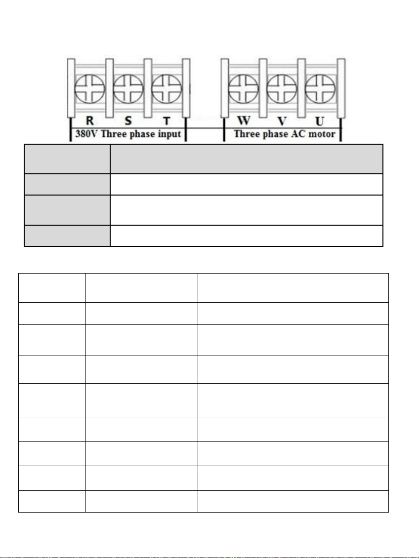
(3). Three-phase input and output (for AT3)
Terminal
label
Function description
R,S,T Three phase AC 380V input terminal
U, V, W
Output terminal connect to
Three
phase
380V AC motor
GND Grounding terminal
Page 4

Section
speed input 1
Section
speed input 2
Section
speed input 3
Original
Frequency
Main Speed 1 1 1 50
Section speed 1
1 1 0 45
Section speed 2 1 0 1 40
Section speed 3 1 0 0 35
Section speed 4 0 1 1 30
Section speed 5 0 1 0 25
Section speed 6 0 0 1 20
Section speed 7 1 1 1 15
Note
:
0 means input Port connect with COM, 1 means
disconnect.
3. Multi-speed input Frequency control table :
4页
Port
Functional
description
Instructions
COM Common GND
VL1
External
analog
voltage
input
0-5V/10V Analog voltage input
CI
External current signal
input
4-20mA Current input
SP1 Open-collector output 1
SP2 Open-collector output 2
5V/10V 5V/10V power output
supply 5V/10V 20mA power output
TC Relay output C
250VAC 5A/30VDC 3A
TA and TB Normal Close ,TA and TC
Normal Open
TB Relay output B
TA Relay output A
Page 5

5页
4. Basic operation wiring diagram
(1) Single-phase input three-phase output (for AT1 )
(Three phase 220V, if 380V Star-connection method
needs to change to the 220V Delta-connection method)
Page 6

(2). Single-phase input and output (for AT2)
(220V single phase motor, Non-removed capacitor
/ Removed capacitor)
6页
Page 7

(3). Three-phase input and output (for AT3)
(380V three phase input, connect with 380V three
phase motor)
7页
Page 8

5. Operation panel
8页
Page 9

9页
6. Keys instructions:
Icon Function description
1
(Programming)
For selecting mode or Programming mode (it is
available not mater the Inverter start or stop),
press this key for modifying parameters.
2
(Function / Save)
Function data setting key. Normal mode: press
this key to display the information of the Inverter,
such as target frequency, output frequency and
current, temperature;
3
Key
(▲)
Parameter
number or
parameter value
increase
Short press this key, then
the numerical value will
change gradually. Long
press this key, then the
numerical value will change
rapidly
4
Key
(▼)
Parameter
number or
parameter value
decrease
5
Shift
Shift in programming mode, jog in normal mode
6
Forward / Reverse Forward / Reverse switching key
7
Start Start Inverter output
8
Stop / Reset
Break down, fault resetting
Note
Please modify the parameters under the stop state, otherwise, the
changed parameters cannot be saved.
Page 10

10页
1. Parameter specification
Paramet
er
Parameter
specification
Parameter range Default Unit
P00 Maximum voltage 0---220.0/380.0 220/380 V
P01 Reference frequency 0---400.0 50 Hz
P02 Intermediate voltage 0---220.0/380.0 110/190 V
P03
Intermediate
frequency
0---400.0 25 Hz
P04 Minimum voltage 0---220.0/380.0 0 V
P05 Minimum frequency 0---400.0 0 Hz
P06 Maximum operating 0---400.0 65.0 Hz
P07 Minimum operating 0---400.0 0 Hz
P08 Hide password 0---65535 00000
P09 Input password 0---65535 0
P10
Working frequency
source
0: Panel keyboard;
1: Panel potentiometer;
2: External analog signal
3: RS485.
1
P11
Start/stop
control source
0: Panel keyboard;
1: RS485;
2: External port.
0
Chapter 2 Parameter specification
Page 11

11页
P12
Stopping Modes
0: Inertial stop;
1: Deceleration stop;
2: Brake stop;
3: Emergency brake.
1
P13 Braking time 0---2.5 0.5 S
P14 Braked Voltage 0---140.0 20 V
P17 Machine number
1-255 1
P18 Operating arrival 0---100.0 50 Hz
P20
Over temperature
protection selection
1---80 80
P21 Revolution for 50Hz 0-8000 2800
P22
Carrier setting
1---10 (1-20 for High Ver) 10
P23
Frequency adjusting step
size
1---100 5 0.1Hz
P24
Overload protection buffer
time
0.1---60.0 3 S
P26
Working frequency
0---400.0 50 Hz
P27
Section speed 1 setting
0---400.0 45 Hz
P28
Section speed 2 setting
0---400.0 40 Hz
P29
Section speed 3 setting
0---400.0 35 Hz
P30
Section speed 4 setting
0---400.0 30 Hz
P31
Section speed 5 setting
0---400.0 25 Hz
P32
Section speed 6 setting
0---400.0 20 Hz
Page 12

12页
P33
Section speed 7 setting
0---400.0 15 Hz
P34
Main rising velocity
1---1000 25 Hz/S
P35
1st rising velocity
1---1000 25 Hz/S
P36
2nd rising velocity
1---1000 25 Hz/S
P37
3rd rising velocity
1---1000 25 Hz/S
P38
4th rising velocity
1---1000 25 Hz/S
P39
5th rising velocity
1---1000 25 Hz/S
P40
6th rising velocity
1---1000 25 Hz/S
P41
7th rising velocity
1---1000 25 Hz/S
P42
Main descent velocity
1---1000 25 Hz/S
P43
1st descent velocity
1---1000 25 Hz/S
P44
2nd descent velocity
1---1000 25 Hz/S
P45
3rd descent velocity
1---1000 25 Hz/S
P46
4th descent velocity
1---1000 25 Hz/S
P47
5th descent velocity
1---1000 25 Hz/S
P48
6th descent velocity
1---1000
25 Hz/S
P49
7th descent velocity
1---1000
25 Hz/S
P50
Multi function input 1
(X1 binding post)
0: invalid, terminal is
non-functioning
1: wire control stop
2: keying stop;
3: keying operation;
4: stop keying;
Page 13

13页
P50
Multi function input 1
(X1 binding post)
5: wire forward operation
6: wire reverse operation;
7: reservation
8: error reset signal;
9: wire reversing switch;
10: keying forward switching;
11: keying forward switching;
12: reverse switch keying;
13: section speed input 1;
14: section speed input 2;
15: section speed input 3;
16: external error signal.
17: Jog Forward;
18: Jog Reverse;
19: Emergency stop;
20: Relay Control.
13
P51
Multi function input 2
14
P52
Multi function input 3
15
P53
Multi function input 4
5
P54
Multi function input 5
6
P55
Multi function input 6
9
P58
Multi function input 1
(SP1)
0: invalid, no output;
1: operating instructions;
2: set arrival instructions
3: fault indication;
5: Emergency stop;
6: For P50---P55=20;
0
P60
Multi function input 2
Idem (Relay output)
0
P62 Display options
0: setting frequency;
1: operating frequency;
2: revolution 3: current;
4: temperature; 5: time;
0
Page 14

14页
P65
Power on options
0: normal power on;
1: report error with start signal
when power on;
2: Power on forward;
3: Power on reverse.
0
P66 Input stabilization time 0---65535 60
mS
P67 Voltage coefficient 0---65535 28500
P68 Under voltage setting 0---220/380 60/180 V
P69 Overvoltage setting 220.0---400/680 400/600 V
P70 Torque compensation
options
0: P72 is compensation amount;
1: Multiply P72 by P71 after P71
minus input voltage
0
P71
Torque compensation
voltage
0---300.0 10 V
P72
Torque compensation
setting
0---100 0
P73
Maximum external
analog 0---65535
31440
P74
Minimum external
analog 0---65535
2096
P75
Zero current
compensation value
0---65535
1130
P76 Current coefficient 0---65535
9500
P77 Parameter reset
0---65535
(It is the reset when 54321)
0
P78 Main current overload 0-65535 3000 mA
P79 First current overload 0-65535 3000 mA
P80
Second current overload
0-65535 3000 mA
P81 Third current overload 0-65535 3000 mA
P82 Fourth current overload 0-65535 3000 mA
P83 Fifth current overload 0-65535 3000 mA
Page 15

15页
P08 is the hidden password, it always shows only 00000, not the actual
value.
When input the value of P09=the hidden value of P08, the P08 shows
hidden value, and the P08 and other parameters can be changed. The
P09 will be nullified when unplug the power cable to restart.
When P127=65535, the function of countdown do not start.
When P127﹤65535, the function of countdown will start, the P127
will minus 1 when the Inverter runs for one hour. The frequency
converter will be stopped when the countdown of P127 to 0 hour.
2. Parameter setting password and Down time stop:
P84 Sixth current overload 0-65535 3000 mA
P85 Seventh current overload 0-65535 3000 mA
P86 Jog forward frequency 0---400.0 20 Hz
P87 Jog reverse frequency 0---400.0 20 Hz
P88 Jog rising velocity 1---1000 50 Hz/S
P89 Jog descent velocity 1---1000 50 Hz/S
P90Jog stopping modes
0: Inertia stop;
1: Decelerate stop;
2: Braking stop;
3: Emergency brake.
1
P91 Jog braking time 0---2.5 0.1 S
P92
Phase options (AT2
only)
0:Three-phase
2:Three-line single phase
0
P98
The frequency of
closing the U-phase (AT2)
0-50Hz 0 Hz
P127 Remaining hours 0---65535 65535
H
Page 16

16页
Fault Code Display Fault Code Description
Err 1
Short Circuit/Current overload/Power
Module protection
Err 2
Undervoltage protection
Err 3
Overvoltage protection
Err 4
Driving Circuit Failures
Err 5
Input at startup when electrified
Err 6
Over current protection
Err 7
Overtime
Err 8
Excessive temperatures for radiator
Err 9
External fault
Chapter 4 Fault Code
4. Parameter setting procedure:
1. Press the programming key to enter into the programming state;
2. Use the arrow keys and shift key to find the parameters that
need to be modified;
3. Press function / save key to enter into the parameter;
4. Use the arrow keys and shift key to amend the parameter value;
5. Press the function / save key to store the parameter;
6. Press the programming key to exit the programming state.
 Loading...