

TopEnd®Force™
Force-2,ForceG,ForceK,ForceRX,ForceCC
ENHandcycleSeries
UserManual
ThismanualMUSTbegiventotheuseroftheproduct.
BEFOREusingthisproduct,readthismanualandsaveforfuturereference.

©2013Invacare®Corporation
Allrightsreserved.Republication,duplicationormodificationinwholeorinpartisprohibitedwithout
priorwrittenpermissionfromInvacare.Trademarksareidentifiedby™and®.Alltrademarksare
ownedbyorlicensedtoInvacareCorporationoritssubsidiariesunlessotherwisenoted.
ShimanoisaregisteredtrademarkofShimanoInc.
3-in-1oilisaregisteredtrademarkofAmericanHomeProductsCorporation.
TeflonisaregisteredtrademarkofE.I.DuPontDeNemoursandCompany.
PhillipsisaregisteredtrademarkofthePhillipsScrewCompany.
WD-40isaregisteredtrademarkofWD-40Company.
LemondisaregisteredtrademarkofLemondFitness.
CaneCreekisaregisteredtrademarkofCaneCreekCyclingComponents,Inc.
PleaserecordyourserialnumberSN#_________________.
TheSNisrequiredforanywarrantyclaimsandplacingaftermarketpartsorders.

Contents
1General......................................5
1.1Symbols..................................5
1.2IntendedUse..............................5
1.3Dealer/TechnicianInformation.................5
2Safety........................................6
2.1GeneralGuidelines..........................6
2.2ProperFit................................6
2.3OperatingInformation.......................7
2.4TransferringInto/OutoftheHandcycle...........9
......................................10
2.5SafetyInspectionChecklist....................11
3Overview.....................................12
3.1LabelLocations............................12
Force-2Label............................12
ForceGLabel...........................13
ForceKLabel............................14
ForceRXLabel..........................15
ForceCCLabel..........................16
3.2TypicalProductParameters...................17
3.3ComponentIdentification.....................27
3.4TirePressureConversion.....................32
4Assembly-Force-2Only.........................33
4.1AssemblingtheForce-2Handcycle..............33
5Operation....................................41
5.1GeneralOperationInstructions................41
5.2ShiftingGears.............................43
5.3Backing-UpandManeuveringinTightAreas........45
5.4Braking..................................46
5.5Steering,TurningandCornering................48
5.6DeterminingToeIn/ToeOut..................49
5.7AdjustingToeIn/ToeOut.....................50
5.8AdjustingHandCrank.......................50
5.9AdjustingSeatFore/Aft.......................51
5.10AdjustingBackAngle........................52
5.11ReplacingtheBolted-onHeadrest...............54
6ServiceProcedures.............................55
6.1InstallingRearWheelswithThreadedAxles.......55
6.2ReplacingTire/TubeandTuning/Replacementof
Spokes..................................55
6.3ReplacingCamberInserts.....................55
6.4Removing/InstallingtheFork...................56
6.5Removing/InstallingtheFrontWheel.............57
6.6ReplacingtheCrankArms....................58
6.7Installing/Removing/AdjustingtheSteering
Dampener................................60
6.8InstallingTwenty-SevenorThirtySpeedCassette
Chain...................................61
6.9AdjustingTwenty-SevenorThirtySpeedCassette
Chain...................................62
6.10InstallingHandCrankHandles.................62
6.11InstallingV/SCrankarmHandles................62
6.12Adjusting/ReplacingthePrimaryCaliperBrakeand
ParkingBrake.............................63
6.13DiscBrakes...............................64
6.14ReplacingSeatUpholstery....................65
6.15ReplacingBackCushion......................66
6.16IntegratedBackrestStrapReplacement...........66
6.17Replacing/AdjustingtheFootrest................67
6.18Using/ReplacingtheFootrestStrap..............68
7Troubleshooting...............................70
7.1Troubleshooting...........................70

8Maintenance..................................71
8.1SuggestedMaintenanceProcedures..............71
9Options......................................72
9.1InstallingSafetyLights........................72
9.2InstallingtheWaterBottle....................73
9.3UsingSafetyHelmet.........................74
9.4InstallingtheComputer......................74
9.5Assembling/Adjusting/UsingtheHandcycle
Rack....................................75
9.6UsingtheAlignmentGauge....................77
9.7AdditionalOptions..........................78
10Warranty.....................................82
10.1Warranty................................82
10.2European,Australian,andNewZealandLimited
WarrantyInformationandCustomerService.......84
10.3UsabilitySurvey............................85

General
1General
1.1Symbols
Warnings
Signalwordsareusedinthismanualandapplytohazardsorunsafe
practiceswhichcouldresultinpersonalinjuryorpropertydamage.
Seetheinformationbelowfordefinitionsofthesignalwords.
WARNING!
–Warningindicatesapotentiallyhazardoussituation
which,ifnotavoided,couldresultindeathorserious
injury.
CAUTION!
–Cautionindicatesapotentiallyhazardoussituation
which,ifnotavoided,mayresultinpropertydamage
orminorinjuryorboth.
–Indicatesahazardoussituationthatcouldresultin
damagetopropertyifitisnotavoided.
Givesusefultips,recommendationsandinformationfor
efficient,trouble-freeuse.
ThisproductcomplieswithDirective93/42/EEC
concerningmedicaldevices.
ThelaunchdateofthisproductisstatedintheEC
declarationofconformity.
1.2IntendedUse
TopEndHandCyclesaredesignedandbuiltsolelyfortransportation
ofasingleriderforuseinrecreational,roadracing,timetrailingand
offroadenjoyment.Theyareintendedtobeusedforlonger,faster
ridesinrecreationalareasincludingpaved,crushedgravel,riding
pathsoroffroadcourses.Theyarenotintendedtobeusedasadaily
wheelchairorthetreatmentofanymedicalconditionbutonlyfor
recreationalpurposes.Anyotherusedisprohibited.
Max.userweight:250lbs(113.4kg).
1.3Dealer/TechnicianInformation
Theterm“qualifiedtechnician”inthismanualreferstoanInvacare
qualifiedtechnicianoraShimano®certifiedbicyclerepairtechnician.
1171790-B5

TopEnd
®
Force™
2Safety
2.1GeneralGuidelines
Thesafetysectioncontainsimportantinformationforthesafe
operationanduseofthisproduct.
WARNING!
–DONOTusethisproductoranyavailableoptional
equipmentwithoutfirstcompletelyreadingand
understandingtheseinstructionsandanyadditional
instructionalmaterialsuchasowner’smanuals,service
manualsorinstructionsheetssuppliedwiththis
productoroptionalequipment.Ifyouareunableto
understandthewarnings,cautionsorinstructions,
contactadealerortechnicalpersonnelbefore
attemptingtousethisequipment-otherwise,injury
ordamagemayoccur.
–AqualifiedtechnicianMUSTperformtheinitialsetup
ofthiswheelchair.also,aqualifiedtechnicianmust
performallproceduresspecificallyindicatedinthe
manual.
WARNING!
ACCESSORIES
–Invacareproductsarespecificallydesignedand
manufacturedforuseinconjunctionwithInvacare
accessories.Accessoriesdesignedbyother
manufacturershavenotbeentestedbyInvacareand
arenotrecommendedforusewithInvacareproducts.
2.2ProperFit
ThehandcycleMUSTbeadjustedtofittherider.Checktheseat
position,backangle,threadedaxles,footrestfore/aftposition,hand
crankheightforproperfitandsmoothoperationofyourhandcycle.
Refertoadjustmentproceduresbelowtoachievethefollowing.
•TheriderMUSTbeabletoseeoverthehandcrank.
•TheriderMUSThaveaslightbendattheelbowwhenthe
handpedalsaretowardthefrontofthehandcycle(farthestfrom
therider’sface).
•TheriderMUSThaveaslightbendatthekneewhenfeetarein
thefootrests.Feetshouldbeflatagainstfootresthoop.
•ForceSeriesrequiresan18”turningradius.Iflegtouches
tireduringturnandtheusercannotsensethis,alegguard
attachmentisrecommended.
•Therider’skneesMUSTnotobstructhandcrankoperation.
61171790-B

Safety
2.3OperatingInformation
WARNING!
TRANSPORT
–InvacarerecommendsthatahandcycleuserisNOT
transportedinvehiclesofanykindwhileinahandcycle.
Asofthisdate,theDepartmentofTransportationhas
notapprovedanytie-downsystemsfortransportation
ofauserwhileinahandcycle,inamovingvehicleof
anytype.
SEATPOSITIONINGSTRAP
SERIOUSINJURYCANOCCURINTHEEVENT
OFAFALLFROMTHEPRODUCT.
–ALWAYSwearyourseatpositioningstrap.Invacare
stronglyrecommendsusingtheseatpositioningstrap
asanadditionalsafeguardforthehandcycleuser.The
seatpositioningstrapisapositioningbeltonly.Itis
notdesignedforuseasasafetydevicewithstanding
highstressloadssuchasautooraircraftsafetybelts.
Ifsignsofwearappear,thebeltMUSTbereplaced
IMMEDIATELY.
WARNING!
BRAKES
–Ifthebrakecableshowsignsofwearorifithas
becometangledbecauseofimpropertransportation
techniques,thecableMUSTbereplacedorthebrake
mayfail.Shouldtheprimarybrakefail,theparking
brakecanbeusedabackupemergencybrake.
–Beforeridingyourhandcycle,ALWAYScheckthe
functionofthebrakes.Besurethatthebrakesand
allotherfeaturesofyourhandcycleareoperating
properly.
WARNING!
RISKOFINJURYORDAMAGE
–Care,considerationandpracticeMUSTbetakenand
observedinthefollowingsafetypoints.Otherwise,
injuryordamagemayoccur.
–Safeuserequiresthecloseattentionoftheuseras
wellastheassistant.Thisusermanualpointsoutthe
mostcommonproceduresandtechniquesinvolvedin
thesafeoperationandmaintenanceofthehandcycle.
Itisimportanttopracticeandmasterthesesafe
techniquesuntilyouarecomfortableinmaneuvering
thehandcycle.
–AhelmetMUSTALWAYSbewornwhenoperating
thehandcycle.
–ShoesMUSTAlwaysbewornandfeetMUSTbe
securedtothefootrestswiththestrapswhen
operatingthehandcycle.
–ALWAYSkeepfingersandhandsawayfromthechain
whileusingthehandcycle.
1171790-B7

TopEnd
®
Force™
WARNING!
RISKOFINJURYORDAMAGE
–TheBackrestMUSTbeadjustedproperly.Otherwise,
user’selbowsmaycontactrearwheelsduringuse.
Operatewithcaution.
–DONOTletchildrenplaynearthehandcrankorthe
chain.Otherwise,injuryordamagemayoccur.
–Theuserisresponsiblefornormalupkeepand
maintainingthehandcycleinproperoperating
condition.
–Themanufacturerisnotresponsibleforfailure,
damageorinjurycausedbyimproperoperationor
maintenancebytheend-user.
–Todetermineandestablishyourparticularsafety
limits,practicetransferringactivitiesinthepresenceof
aqualifiedhealthcareprofessionalbeforeattempting
activeuseofthehandcycle.
–CareMUSTbetakenwhenoperatingonroads,streets
orhighways.ALWAYSusesafetyflagthatisprovided
withthehandcycle.
–Operationofthehandcycleissubjecttoalltraffic
rulesandregulations.(Thismayincludetheuseofa
safetylightsandreflectorsfordusk/nightriding.)Give
pedestrianstherightofway.
–Slowdownwhenturningorcornering,otherwise
injuryordamagemayoccur.
–Useproperhandsignalswhenturning.
–Slowdownatallstreetintersectionsandobserveto
theright,totheleftandbacktorightagainbefore
proceeding.
–DONOTattempttomoveupordownaninclinewith
aniceoroilfilm.Avoidallsurfacehazards.
WARNING!
RISKOFINJURYORDAMAGE
–DONOTattempttorideovercurbsorobstaclesor
speedbumps.Doingsomaycauseyourhandcycleto
"bottomout"and/orturnoverandcausebodilyharm
ordamagetothehandcycle.
–DONOTattempttoliftthehandcyclebyany
removable(detachable)parts.Liftingbymeansofany
removable(detachable)partsofanhandcyclemay
resultininjurytotheuserordamagetothehandcycle.
–DONOTstandontheseatorframeofthehandcycle.
–DONOTcarryanyriders.
–DONOTcarryanyitemsthatmayobstructyour
vieworprohibityoufromoperatingthehandcycle
properly.
TIREPRESSURE
–DONOTuseyourhandcycleunlessithastheproper
tirepressure(p.s.i.).DONOToverinflatethetires.
Failuretofollowthesesuggestionsmaycausethetire
toexplodeandcausebodilyharm.
–DONOTrideonaflatorunderinflatedtires.Riding
onflatorunder-inflatedtirescancauseinjury,aswell
as,damagetothetire,tubeandhandcyclewheels.
WEIGHTLIMITATION
–TheInvacareForcehandcycleshaveaweightlimitation
of250lbs(113.4kg).
81171790-B

Safety
WARNING!
RISKOFINJURYORDAMAGE
STABILITYANDBALANCE
–Forstabilityandproperoperationofyourhandcycle,
youMUSTatalltimesmaintainproperbalance.
Turningandcorneringaffectsthestabilityandbalance
ofthehandcycleanduser.Yourhandcycleshould
remainuprightandstableduringturnsandcornering
whenoperatedcorrectly.
–Invacarerecommendsusingseatpositioningstrapfor
additionalsafety.
ANOTETOHANDCYCLEASSISTANTS
–Whenlearningassistancetechniquesforthehandcycle,
haveanexperiencedassistanthelpyoubefore
attemptingitalone.
–Whenyouareassistingwithatransferto/fromthe
handcycle,remembertousegoodbodymechanics.
Keepyourbackstraightandbendyourkneeswhen
liftingorpositioningthehandcyclefortheend-user.
–Also,beawareofdetachableparts.Thesemust
NEVERbeusedforliftingsupportsortomovethe
handcycle,astheymaybeinadvertentlyreleased,
resultinginpossibleinjurytotheuserand/orassistant.
PERCENTAGEOFWEIGHTDISTRIBUTION
–Transferringinandoutofthehandcycle,turningand
corneringwillcauseachangetothenormalbalance,
thecenterofgravity,andtheweightdistributionofthe
handcycle.Todetermineandestablishyourparticular
safetylimits,practicetransferringactivitiesinseveral
combinationsinthepresenceofaqualifiedhealthcare
professionalbeforeattemptingatransferalone.
–Properpositioningisessentialforyoursafety.
2.4TransferringInto/OutoftheHandcycle
WARNING!
–Beforeattemptingtotransferinoroutofthe
handcycle,everyprecautionshouldbetakentoreduce
thegapdistance.Positionthehandcycleonlevel
groundandascloseaspossibletotheobjectyouare
transferringintooroutof.
–TheobjectyouaretransferringintooroutofMUST
alsobesecuredbeforeattemptinganytransfer.
–TheparkingbrakeofthehandcycleMUSTbeengaged
beforeattemptinganytransfer.
WHEELCHAIRS
–Wheellocksarenotbrakes.
–Engagingthewheellocksmaynotpreventthe
wheelchairfrommovingonallfloorsurfacesincluding
thosethatmaybewetorslick.
–ALWAYSexercisecautionwhentransferringintoor
outofthewheelchair.
CAUTION!
–Whentransferring,positionyourselfasfarbackas
possibleintheseat.Thiswillpreventdamagetothe
upholstery.
Thisactivitymaybeperformedindependentlyprovidedyou
haveadequatemobilityandupperbodystrength.
1.Positionthehandcycleonlevelgroundandascloseaspossible
alongsidetheobjectto/fromwhichyouaretransferring.
2.Ifpossible,positionthehandcycleata45°angletotheobject
to/fromwhichyouaretransferring.
3.Ifinstalled,applytheparkingbrakeonthehandcycle.
1171790-B9
TopEnd
®
Force™
4.Positionthehandcyclehandlesasfarforwardaspossible.This
willcreatemoreroomtotransfer.
Ifnecessary,liftthefrontwheeloffthegroundand
rotatethefronttire.
5.Secureobjectthatyouaretransferringintooroutof.Apply
wheellocks(ifinstalled)iftheobjectisahandcycle.
Duringindependenttransfer,littleornoseatplatform
willbebeneathyou.Althoughitmaybedifficultto
wedgethetransferboardbetweenthehandcycleseat
andthehandcycleseat,useatransferboardifnecessary.
6.Liftandplaceleftlegpastthefrontframeacrosstheseatand
overthecentertube.
7.Placeonehandonfarsideofseat.
8.Shiftbodyweightontoobjectwhiletransferring.
9.Totransferoutofthehandcycle,reversetheprocedureand
usethebackresttopushoff.
WARNING!
–Ifinstalledonhandcycle,parkingbrakeandwheellocks
MUSTbeengaged.
Thestepsbelowarespecificallyfortransferto/fromawheelchairand
donotcorrespondtothestepsintheprocedureontheprevious
page.Followasimilarproceduretotransferto/fromanobjectother
thanawheelchair.Refertothestepsonthepreviouspageformore
information.
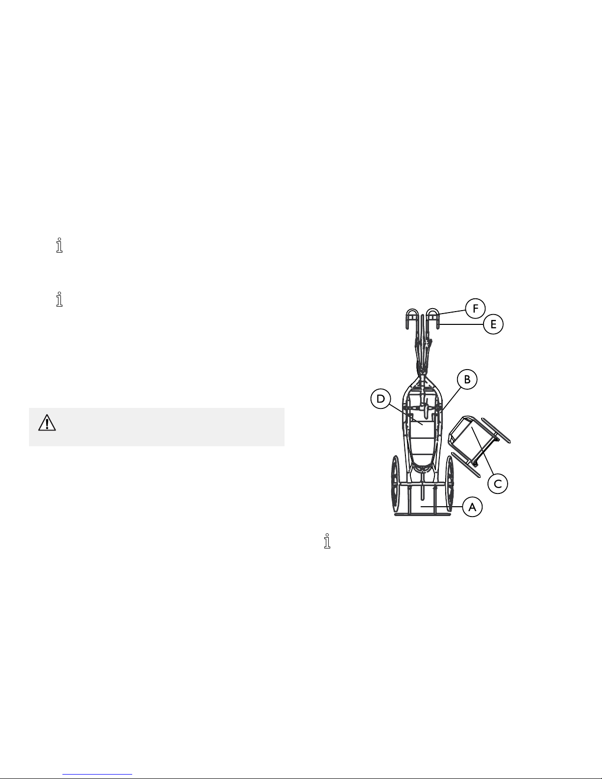
STEPA:Shiftbodyweighttotheedgeofthewheelchairupholstery
closesttothehandcycleA.
STEPB:LiftandplaceLEFTlegacrossseat.
STEPC:PlaceLEFThandontheleftsideofhandcycleseatframe
B,NOToncrank.
STEPD:PlaceRIGHThandonthewheelchairframeC.
STEPE:LiftandshiftweightdownintohandcycleseatD.
STEPF:PlacebothlegsontohandcyclefootrestsEandsecuresafety
straps.
Handcycleshownforclarity.
Handcyclepedalsarerotatedtothe3o’clockposition.
101171790-B

Safety
2.5SafetyInspectionChecklist
Everysixmonthsorasnecessary,takeyourTopEnd
handcycletoaqualifiedtechnicianforathoroughinspection
andservicing.Regularcleaningwillreveallooseorworn
partsandenhancethesmoothoperationofyourhandcycle.
Forsafeandproperoperation,yourhandcycleMUSTbe
caredforjustlikeanyothervehicle.Routinemaintenance
willextendthelifeandefficiencyofyourhandcycle.
Initialadjustmentsshouldbemadetosuityourpersonalbody
structureandpreference.Thereafterfollowthesemaintenance
procedures:
Inspect/AdjustInitiallyandWeekly
qInspectforbentorbrokenframe.
qInspectparkingbrake-Adjustbrakeshoestofrontrim.Check
forwornormissingshoes.Checkforwaxoroilonrim.
qEnsurecableanchorisattachedsecurelytobrakearm.
qEnsurethebrakesareworkingbeforeyoubeginaride.When
fullyapplied,thehandcycleshouldcometoacompletestop.
CAUTION!
–Aswithanyvehicle,thewheels/castorsandtires
shouldbecheckedperiodicallyforcracks,flatspots
andwear,andshouldbereplaced.
qEnsureaxlenutsaretight.Wheelshouldbecenteredinfork.
Keepwheelbearingsadjustedandkeepspokestightandwheel
inproperalignment.
qInspectrimandforkassemblyfordamage.
qEnsureaxlenutandwheelmountingnutsaresecure.
qInspectwheelsforexcessivesidemovementorbindingwhen
liftedandspun.
qInspectforflatspots,wearandproperinflation.
qInspectchain/chainguardfordamage,rust,tensionandstretch.
Adjustifnecessary.Lubricateeachlink(3-in-1oil®oraquality
bikelubricant).Checkfordamageorlooseness.
qAdjustshifter/brakecablesaccordingtoshifter/brake
manufacturer'sinstructions(includedwiththehandcycle).
qInspectfrontfork.Keeptightandlubricate(Allpurposegrease).
qInspectfootrestmountinghardwareistightandfootrestsecure.
qInspectfootreststrapsforwetnessand/ordamage.
qInspectseatpositioningstrapforanysignsofwear.Ensure
bucklelatches.Verifyhardwarethatattachesstraptoframeis
secureandundamaged.Replaceifnecessary.
qInspectupholsteryforripsorsagging.
qCleanupholsterywithlightdetergentandwater.
qCheckthatalllabelsarepresentandlegible.Replaceifnecessary.
qEnsurethataxlesarefreeofdebris.
Inspect/AdjustPeriodically
qInspectupholsteryforripsorsagging.
qCleanupholsterywithlightdetergentandwater.
qInspecthandgripsforlooseness.Ifloose,replace.
qCheckthatalllabelsarepresentandlegible.Replaceifnecessary.
1171790-B
11
TopEnd
®
Force™
3Overview
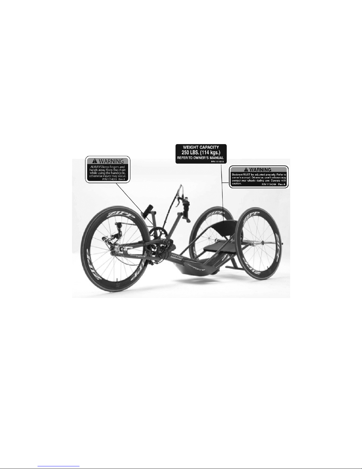
3.1LabelLocations
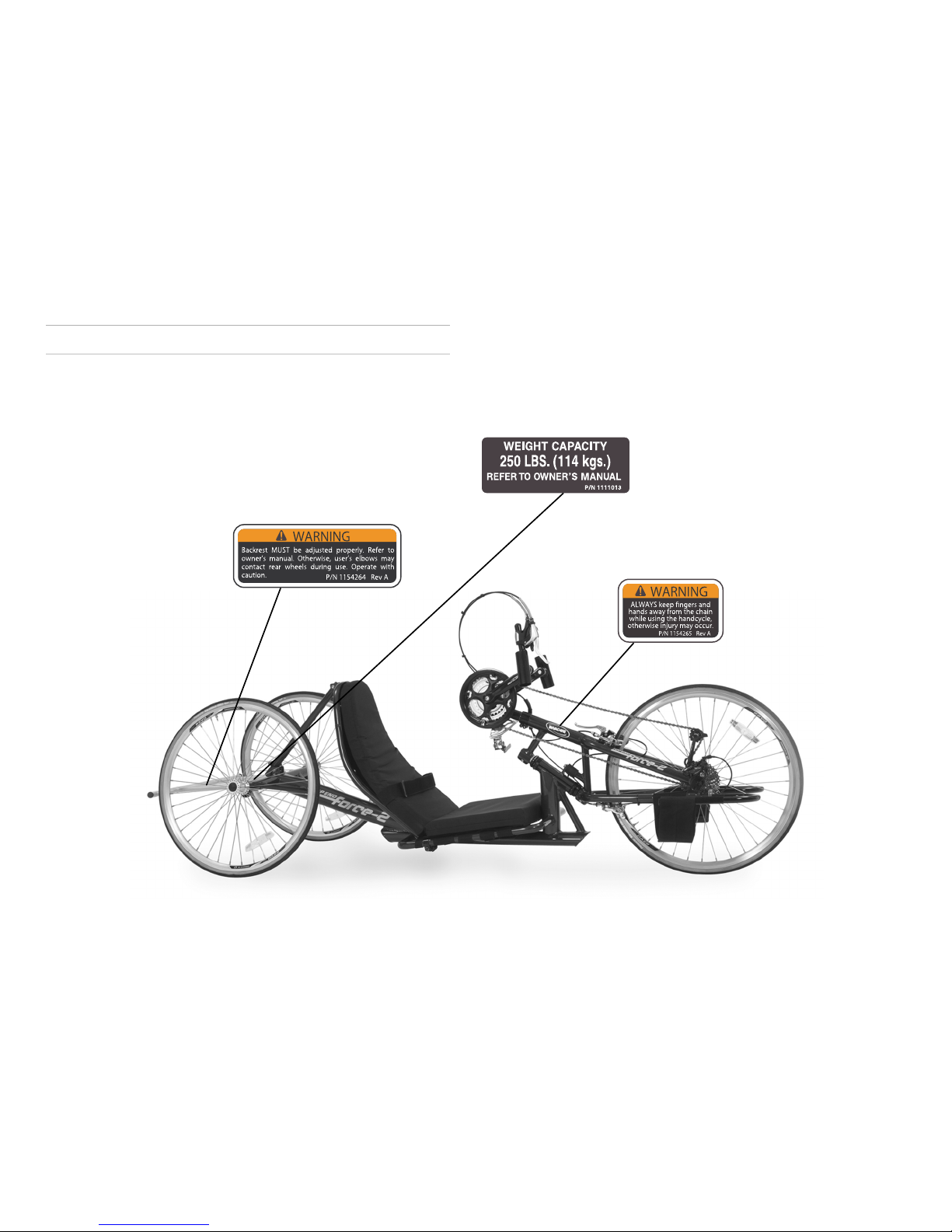
Force-2Label
12
1171790-B
Overview
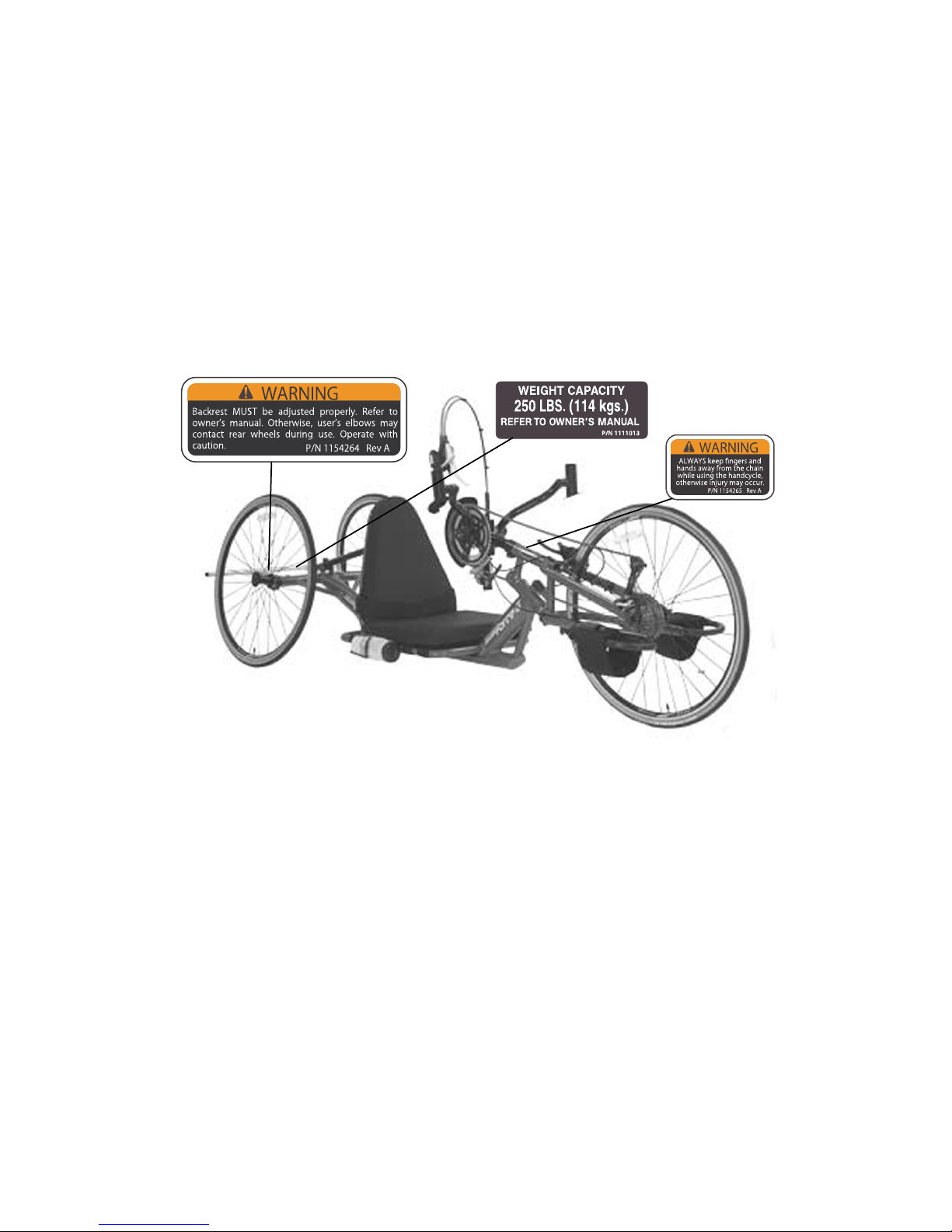
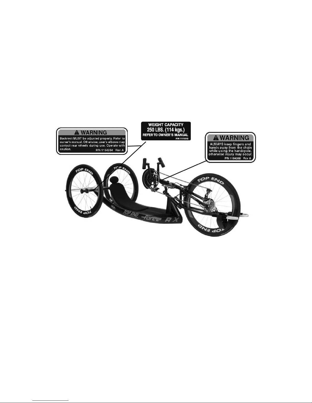
ForceGLabel
1171790-B13
TopEnd
®
Force™
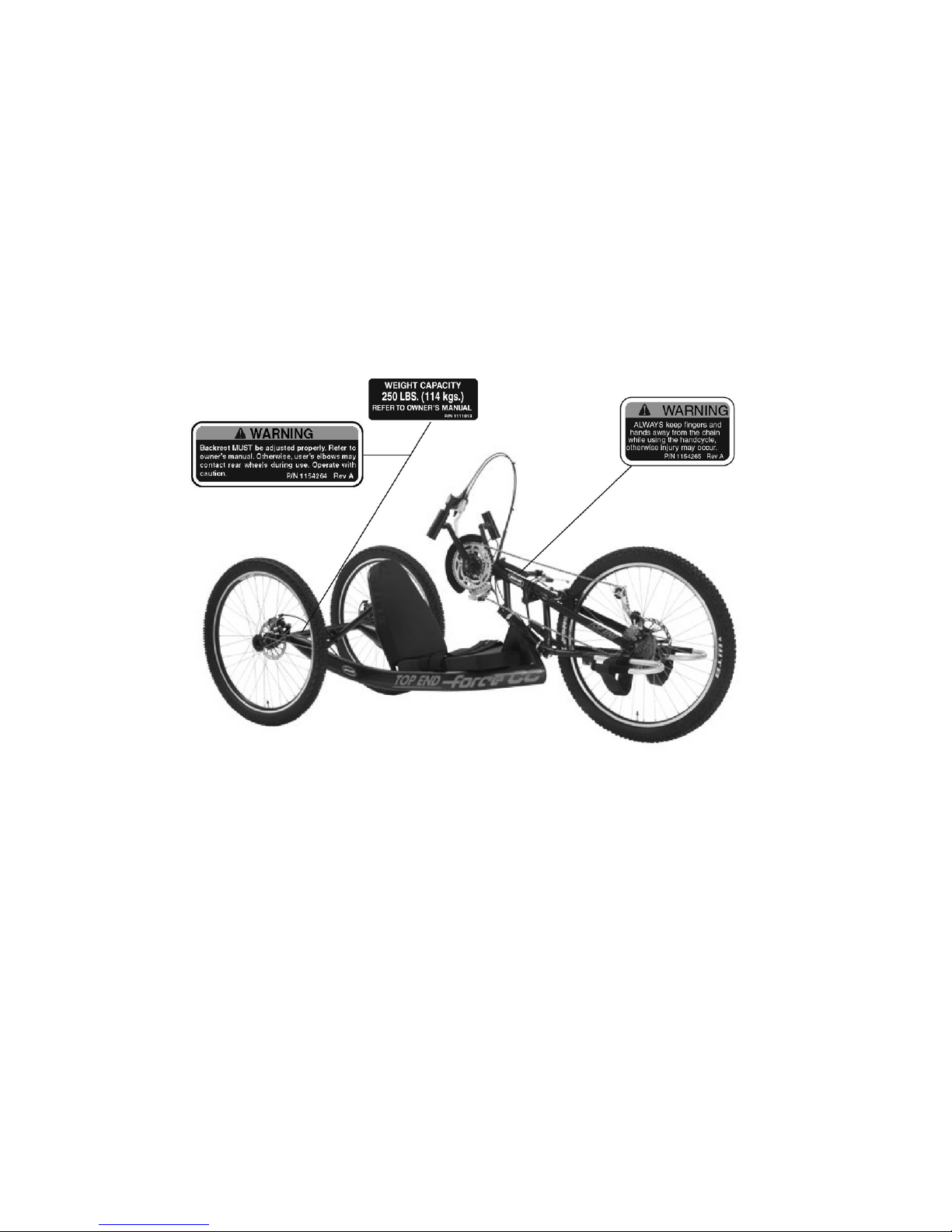
ForceKLabel
14
1171790-B
Overview
ForceRXLabel
1171790-B15
TopEnd
®
Force™
ForceCCLabel
161171790-B

Overview
3.2TypicalProductParameters
TopEndForce-2
SeatWidth:15or17inches(38.1to43.1cm)
SeatDepth:14inches(35.6cm)
Seat-to-Floor(approx.):SeattoFlooris7inches(17.8cm)measuredatthemidpointofseatwith2"(5.1cm)cushion
BackStyle:AdjustableBackAngle35°-55°,rearwardsfrom0°(0°=straightup)
BackHeight
Fixed/AdjustableAngle:
24inches(Narrow,Tall)(61cm)
Footrest:
AdjustableForeandAft
Side-WheelClearance:
2inches-*2½inches(5.1-6.4cm)
RearAxle:
Threaded
RearWheelCamber:9°-Standard(22.9cm)
Wheels/Tires:26-inchSpokeHighPerformance(66cm)
Brakes:
Shimano®TiagraBrakeSetoperatedbyRapidFirehands-onbrakemountedonrightorleftpedal
Handles:
Ergonomic,Vertical,OvalizedAluminum
Crankset:
Shimano®Octolink170mmx14”widenon-Vcrank
Hub:
FRONT–Shimano®w/27SpeedExternalCassette
REAR-PrecisionBlackAnodizedwithThreadedAxles
1171790-B17

TopEnd
®
Force™
TopEndForce-2
Spokes:14GaugeStainlessSilver
ShiftLevers:Rapidfirehands-onshiftermountedonrightorlefthandpedalforlowerderailleur
Manualderailerforupperderailleur/chainrings
Gears:27Speed
SeatCushion:
FoamInsert
Upholstery:Nylon
Weight:30lbs(13.6kg)
ShippingWeight:65lbs(29.5kg)
WeightLimitation:250lbs(113.4kg)
StandardEquipment:ChainGuard,SafetyFlag,DraftingBumper,SeatandBackCushions
Options:*seeorderform
Computer,SafetyLights,Helmet,BikeRack,WaterBottleandCage,AlignmentGauge,BackpackHydration
System,IndoorTrainingRoller
181171790-B

Overview
TopEndForceG
SeatWidth:14to18inches(35.6to45.7cm)
SeatDepth:14inches(35.6cm)
Seat-to-Floor(approx.):SeattoFlooris7inches(17.8cm)measuredatthemidpointofseatwith2"(5.1cm)cushion
BackStyle:AdjustableBackAngle55°-90°,rearwardsfrom0°(0°=straightup)
BackHeight
Fixed/AdjustableAngle:
18inches(Narrow,Tall)(45.7cm)
Footrest:
AdjustableForeandAft
Side-WheelClearance:
2inches-*2½inches(5.1-6.4cm)
RearAxle:
Threaded
RearWheelCamber:9°-Standard(22.9cm)
Wheels/Tires:26-inchSpokeHighPerformance(66cm)
Brakes:
CaneCreekoperatedbyRapidFirehands-onbrakemountedonrightorlefthandpedal
Handles:
Ergonomic,Vertical,OvalizedAluminummountedonTopEndV/Scrankset
Crankset:TopEndSorVCrankset,customwidths/lengths(seeorderform)
Hub:
Front–Shimano®/TopEndComponentsw/27SpeedExternalCassette
Rear-PrecisionBlackAnodizedwithThreadedAxles
Spokes:14GaugeStainlessBlack
ShiftLevers:Rapidfirehands-onshiftermountedonrightorlefthandpedalforlowerderailleur
Cableoperatedshifterforupperderailleur/chainrings
1171790-B19

TopEnd
®
Force™
TopEndForceG
Gears:27Speed
SeatCushion:
FoamInsert
Upholstery:Nylon
Weight:30lbs(13.6kg)
ShippingWeight:65lbs(29.5kg)
WeightLimitation:250lbs(113.4kg)
StandardEquipment:ChainGuard,SafetyFlag,DraftingBumper,Seat,BackCushion,Seat
andBackCushions
Options:*seeorderform
Computer,SafetyLights,Helmet,BikeRack,WaterBottleandCage,
AlignmentGauge,BackpackHydrationSystem,CarbonFiberWheels,
IndoorTrainingRoller
201171790-B

Overview
TopEndForceK
SeatWidth:Custom
SeatDepth:Custom
Seat-to-Floor(approx.):Custom
BackStyle:Custom
BackHeight
Fixed/AdjustableAngle:
Custom
Footrest:
Custom
Side-WheelClearance:Custom
RearAxle:
Threaded
RearWheelCamber:3°,0°or6°
Wheels/Tires:26-inchSpokeHighPerformance(66cm)
Brakes:
CaneCreek
®
operatedbyhands-onbrakemountedonrightorlefthandpedal
Handles:
Ergonomic,Vertical,OvalizedAluminummountedonTopEndVcrankset
Crankset:TopEndVCrankset,customwidths/lengths(seeorderform)
Hub:
Front–SRAMwith30SpeedExternalCassette
Rear-PrecisionBlackAnodizedwithThreadedAxles
Spokes:14GaugeStainlessBlack
ShiftLevers:SRAM
®
10SpeedTriggerShiftermountedonRight
Cableoperatedshifterforupperderailleur/chainrings
1171790-B
21

TopEnd
®
Force™
TopEndForceK
Gears:30Speed
SeatCushion:
FoamInsert
Upholstery:Nylon
Weight:30lbs(13.6kg)
ShippingWeight:65lbs(29.5kg)
WeightLimitation:250lbs(113.4kg)
StandardEquipment:ChainGuard,SafetyFlag,DraftingBumper,SeatandBackCushions
Options:*seeorderform
Computer,SafetyLights,Helmet,BikeRack,WaterBottleandCage,AlignmentGauge,BackpackHydration
System,CarbonFiberWheels,IndoorTrainingRoller
22
1171790-B

Overview
TopEndForceRX
SeatWidth:13to18inches(30.5to45.7cm)
SeatDepth:14inches(33cm)
Seat-to-Floor(approx.):5inches(12.7cm)with2inch(5.08cm)cushion
BackStyle:Fixedwithadjustablestrappingoradjustablecarbonfiberback
BackHeight
Fixed/AdjustableAngle:
Customanglerange,27inches(Narrow,Tall)(68cm),Adjustablecarbonfiberback
Footrest:
AdjustableForeandAft
Side-WheelClearance:
2inches-*2½inches(5.1-6.4cm)
RearAxle:
Threaded
RearWheelCamber:3°or6°
Wheels/Tires:26-inchSpokeHighPerformance(66cm)
Brakes:ProForce
Handles:
Ergonomic,Vertical,OvalizedAluminummountedoncrankset
Crankset:TopEndVCrankset,customwidths/lengths(seeorderform)
Hub:
FrontSRAMcomponentswith30speedexternalcassette
Rear:PrecisionBlackAnodizedwiththreaded
Spokes:14GaugeStainlessBlack
ShiftLevers:SRAM
®
10SpeedTriggerShiftermountedonRight
Cableoperatedormanualshifterforupperderailleur/chainrings
1171790-B23

TopEnd
®
Force™
TopEndForceRX
Gears:30speeds
SeatCushion:
FoamInsert
Upholstery:Mesh
Weight:26lbs(11.8kg)
ShippingWeight:65lbs(29.5kg)
WeightLimitation:250lbs(113.4kg)
StandardEquipment:Seat,BackandHeadCushions,ChainGuard,SafetyFlag,DraftingBumper
Options:*seeorderform
Computer,SafetyLights,Helmet,BikeRack,WaterBottleandCage,AlignmentGauge,BackpackHydration
System,CarbonFiberWheels,IndoorTrainingRoller,PowerPlates
24
1171790-B

Overview
TopEndForceCC
SeatWidth:15or17inches(38.1to43.18cm)
SeatDepth:14inches(35.6cm)
Seat-to-Floor(approx.):12inches(17.8cm)measuredatthemidpointofseatwith2"(5.1cm)cushion
BackStyle:AdjustableBackAngle,rearwardsfrom90–120°
BackHeight
Fixed/AdjustableAngle:
18inches(Narrow,Tall)(45.7cm)
Footrest:
AdjustableForeandAft
Side-WheelClearance:
2inches—*2½inches(5.1–6.4cm)
RearAxle:
Threaded
RearWheelCamber:0º—Standard
Wheels/Tires:26inch(66cm)SpokeHighPerformance
Brakes:Frontdiskbrake,operatedbyRapidFirehands-onbrakemountedonrighthandpedal,optionaldualreardisk
brakesoperatedbyforkmountedbrakelever
Handles:
Ergonomic,Vertical,OvalizedAluminummountedonTopEndVcrankset
Crankset:TopEndorVCrankset,length170mm,width14or17inches
Hub:
FRONT—Shimano®/TopEndComponentswith27speedexternalcassette
REAR—PrecisionBlackAnodizedwiththreadedaxles
Spokes:14gaugestainlessblack
ShiftLevers:
Rapid-Fire®hands–onshiftermountedonrighthandpedalforlowerderailleur
Cableoperatedshifterforupperderailleur/chainrings
1171790-B25

TopEnd
®
Force™
TopEndForceCC
Gears:27speed
SeatCushion:
FoamInsert
Upholstery:Nylon
Weight:30lbs(13.6kg)
ShippingWeight:65lbs(29.5kg)
WeightLimitation:250lbs(113.4kg)
StandardEquipment:Seatandbackcushions,chainguard,safetyflag,seat,backcushions,draftingbumper
Options:*seeorderform
Computer,SafetyLights,Helmet,BikeRack,WaterBottleandCage,AlignmentGauge,BackpackHydration
System,CarbonFiberWheels,Clickstraps,IndoorTrainingRoller,LegGuard,Mirror,CrankWidthAdaptor,
HeartRateMonitor
261171790-B
Overview
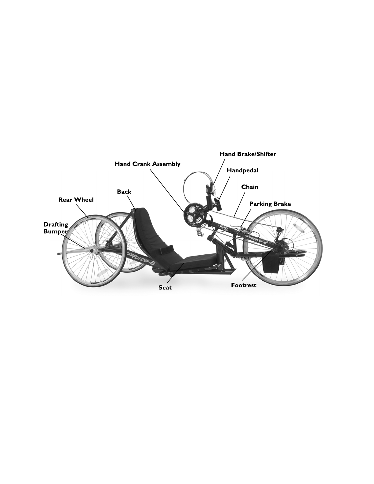
3.3ComponentIdentification
Force-2
1171790-B27

TopEnd
®
Force™
ForceG
281171790-B

Overview
ForceK
ParkingBrakeavailableonrequest.
1171790-B29

TopEnd
®
Force™
ForceRX
Fixedbacknotshown
301171790-B

Overview
ForceCC
1171790-B31

TopEnd
®
Force™
3.4TirePressureConversion
PSIratingisprintedonthesideofthetire.
Conversionformula:1psi=6.895kPa(approx.7kPa).
PSIKILOPASCALS
50345
55
379
60414
65448
70483
75
517
80552
85586
321171790-B

Assembly-Force-2Only
4Assembly-Force-2Only
4.1AssemblingtheForce-2Handcycle
WARNING!
–Afteranyadjustments,repairorserviceandbefore
use,makesureallattachinghardwareistightened
securely.
–Otherwiseinjuryordamagemayoccur.
Requiredtools:
•1/2–inch(1.27cm)boxwrench
•10mmboxwrench
•MetricAllenwrenchset(includes4mm,5mm,and
6mmwrenches)
1.
Tightenthecambertubeclampsoneachendoftheframe.
2.
Insertanaxleintoeachrearwheel.
3.
Usethe6mmwrenchtoattachtherearwheelstotheframe.
Tightensecurely.
1171790-B33

TopEnd
®
Force™
4.
Settheframeonaflatstablesurfacewithasupportunderneath
thefrontframe.
5.
Attachtheplatetotherubberdampenerbythreadingthebolt
intothedampener.
6.
Placetheforkclamplooselyoverthelowerpartofthefork.
7.
Slidethelowerhalfoftheclampoverthelowersectionofthe
frontoftheframe.
341171790-B

Assembly-Force-2Only
8.
Placethesecondclampovertheframeandthefork/frame
attachmentplate.
9.
Securelytightentheupperandlowerclamps.Thereshould
be1/8inch(0.3175cm)gapbetweentheframeandfork/frame
attachmentplate.
CAUTION!
–Donotovertighten.
10.
Looselytightenthedampenerbolttoholdtheforkinplace.
11.
Tocenterthefrontwheel,tightenthesetscrewsoneachsideof
thedampenerplate.Afterthefrontwheeliscentered,tighten
thedampenerscrew.
1171790-B35

TopEnd
®
Force™
12.
Oneachfork,loosenthefootrestclampandslideafootrest
intotheendofthefork.
13.
Attachthefootreststrap.
14.
Removeprotectivebackingfromstickbackhookandloop
fasteneronthebackofthebackcushion.
15.
Alignthebackcushionwiththebackrestandcarefullypressthe
backcushionontothebackrest.
361171790-B

Assembly-Force-2Only
16.
Placetheseatcushionontopoftheseat.
17.
Removethebottomclampofthechainguardwitha5mmAllen
wrench.
18.
Placethechainguardclamparoundthebottombracketand
tightenthescrewontherightside.
19.
Tightentheclampontheleftsidemakingsureitdoesnot
interferewiththechain.
1171790-B37

TopEnd
®
Force™
20.
Removethebackrestsupportbarfromtheclampontheframe.
21.
Removeandretainthebolt,nutandwasher.Insertthecurved
spacers.
22.
Slideawasherontothebolt.Useasmallwrenchtoalignthe
holesandslidetheboltthroughtheholesandsecurewiththe
nut.
23.
Tightenthetopofthebackrestsupportbartothetopofthe
backrestusinga5mmwrenchand10mmboxwrench.
381171790-B

Assembly-Force-2Only
24.
Slidethebackrestsupportbarthroughtheclampontheframe.
Tightenwitha5mmwrench.
25.Adjustthebackrestangleasrequired.Referto.
26.
Removeleftdraftingbumperclamp.
27.
Slidetheflagholderoverthebumperreceiverinplaceofthe
draftingbumperclampremovedinSTEP26.
28.
Slidethedraftingbumperintothebumperreceiversandtighten
bothrightandleftbumperclampswitha4mmwrench.
1171790-B39

TopEnd
®
Force™
29.Insertflag.
30.
TightencranksupportwithanAllenwrench.
31.
Adjustfootreststoproperlengthandtightenwitha5mm
wrench.
DONOTovertighten.Thefootrestsshouldnotturn.
32.
Placecapsoveroutsideofrearwheelaxles.
33.Ifthelegguardisnotinstalled.Referto9.7AdditionalOptions,
page78.
TheRapidFireShifterandBrakeismountedonthe
righthandpedal.Itcanbemovedtothelefthandpedalif
required.
34.TomovetheRapidFireShifterandBrake,loosentheattaching
hardware,movetheassemblytothelefthandpedalandattach
withhardware.Tightensecurely.
401171790-B

Operation
5Operation
5.1GeneralOperationInstructions
WARNING!
–Afteranyadjustments,repairorserviceandbefore
use,makesureallattachinghardwareistightened
securely.Otherwiseinjuryordamagemayoccur.
–Beforeoperatingthehandcycle,reviewtheGeneral
Guidelinesinthisusermanual.
–DONOToperatethehandcycleifhandcrank
obstructsyourview.Ifthehandcrankobstructsyour
view,adjustthehandcrankheightbeforeusingthe
handcycle-otherwiseinjuryordamagemayoccur.
1.Engagetheparkingbrake,ifequipped.Referto.
2.Transferintothehandcycle.Referto2.4TransferringInto/Out
oftheHandcycle,page9.
3.Checkchestclearanceandarmlength.Acombinationofcrank,
backangleandbackrestadjustmentmaybeneededtoachieve
chestclearanceandproperarmlength.
•Backpedalbyplacinghandonhandpedalandpedal
backwards.
•Ifcrankarmsdonotclearchestareamovethebackrest
rearward.Ifequippedwithdiagonalcrankadjustment,
adjustcrankawayfromthebodyallowingmoreroom.This
adjustmentwillmovethecranklowerandaway,andin
additionmayrequireyoutoshortenthechain.
•Checkarmlengthbyplacinghandsonhandpedals.There
shouldbeaslightbendintheelbow.
4.Checkandadjustbackangleforcomfortabletrunkpositionand
properarmlength.
5.Besureyoucanseeoverthetopofthehandcrank.Referto5.8
AdjustingHandCrank,page50.
6.Checklegclearancebybackpedaling.Ifthehandpedalsdonot
clearthelegswhilestationaryinstraightline,raisethecrank
height.Referto5.8AdjustingHandCrank,page50.
7.Ensurethefootrestisadjustedproperly.
Thereshouldbeaslightbendinthekneewhenthesole
oftheshoeistouchingtheinsideedgeofthefootrest.
8.Ensuretheseatisadjustedproperly.
Seatshouldbeadjustedsothatwhenseatedwithfeet
inthefootrests,thereisaslightbendatthekneeanda
slightbendattheelbowwhenthehandcrankisfurthest
away.
9.CheckBrakeandDiscBrakes(ifsoequipped)
•Checkcablesforsignsofwearorfraying.
•Squeezethebrakeleverfirmlyandcheckforproperbrake
function.
•Adjustforpadwearifnecessary.
•Checkpadsforwearandreplaceifnecessary.
•Ensurerotorsarefreeofforeignsubstancesandoils.
10.Secureeachfootinthelegrestswithstrapping.
11.Releasetheparkingbrake,ifequipped.Referto5.4Braking,
page46.
1171790-B
41

TopEnd
®
Force™
WARNING!
–Thehandcrankassemblyisusedforpropelling
andsteeringofthehandcycle.Atleastonehand
MUSTbeonthehandcrankassemblyatalltimes.
Otherwise,injuryordamagemayoccur.
12.Placeatleastonehandontothehandpedals.Rotatethe
handpedalforward(towardthefront)topropelthehandcycle
forward.
42
1171790-B

Operation
5.2ShiftingGears
CAUTION!
–DONOTattempttoshiftgearswhilebikeis
stationary.
–DONOTpressbothshifterleversdownatthesame
time.Doingsomaydamagetheshifterandwillvoid
thewarranty.ThegearsWILLNOTshiftwhenboth
leversarepressedsimultaneously.
–DONOTuseexcessiveforce.Thismaydamagethe
shifterandvoidthewarranty.
Toshiftgears,youMUSTturnthecrankforwardwiththechain
undersometensionwhilethebikeismoving.
Therearetwoshiftersinstalledonthehandcycle.Therighthandpedal
shifteroperatestheninegearsonthelowerderailleurandtheacable
drivenormanualshifter(manualshifterisonForce-2Modelonly)
operatesthethreechainringsontheupperderailleur.
9gearsXthreechainrings=27speeds
10gearsXthreechainrings=30speeds
Shiftingthechainonthelowerderailleurtowardsthecenterlineof
thehandcycleisforclimbing/accelerating(easiercranking)(leverA)
andiscalledadownshift.Movingthechainonthelowerderailleur
outorawayfromthecenterlineofthehandcycleisforspeed(harder
cranking)(leverB)andiscalledanupshift.
Duringoperation,thechainshouldrunsmoothlyoverthechain
rings.Ifthereareproblemswiththechain,discontinueuseand
contactyourlocalbikeshop.
Refertothechartforanexplanationanduseoftheupperderailleur
chainringsincombinationwiththelowerderailleurgears:
•Ifyourpedalingcadenceistooslow,shiftintoalowergear
•Ifyourpedalingcadenceistoofast,shiftintoahighergear
•Thechainshouldnotrubonthefrontofthederailleurchain
guide
•Shiftintoalowergearinordertofacilitateeasystart-up
•NEVERshiftgearswhilestationaryorwhilepedalingbackwards
•Keepeyesontheroadwhenchanginggears
Lowerderailleur
gears(rightshifter)
Upperderailleur
chainrings(manual
shifterorcable
drivenshifter)
Usefor:
1–9SmallestClimbingHillsor
StrongHeadwinds
10–18
Medium
FlatsorGradual
RollingTerrain
19–27
LargestDescendingHillsor
StrongTailwinds
1171790-B43

TopEnd
®
Force™
LowerDerailleur(RightSideShifter)
•ShiftingfromHarderGearstoEasierGears(Downshift)—
Firmlypresstheshifterdowntodownshift.
RapidFireorTriggerShifter—
Range:1–9
Pushshiftleverclosesttocenterwiththumbandrelease.
Repeatuntilthedesiredgearisachieved.
GripTwistShifter-
Range:1–9
Twisttheshifterfromnumbertonumber(5to4,4to3,3to
2,etc.)untilthedesiredgearisachieved.
SRAMDoubleTapRedShifter
•ShiftingfromEasierGearstoHarderGears(Upshift)—
Lightlypresstheshifterdowntoupshift.
44
1171790-B

Operation
RapidFireorTriggerShifter—
Pullshiftleverlocatedtowardstheoutsideusingthumborindex
fingerandrelease.Repeatuntilthedesiredgearisachieved.
GripTwistShifter—
Twisttheshifterfromnumbertonumber(4to5,5to6,6to
7,etc)untilthedesiredgearisachieved.
UpperDerailleur(ManualShifterorCableDrivenShifter)
•ShiftingfromEasierorSmallerChainringtoHarderorLarger
Chainring(Upshift)—
CableDriven—
Pushleverdownuntilchainrunssmoothlyoverthechainring
teethwhilethehandcycleismoving.
ManualShifter(Force-2Only)—
Moveshifterleverup.
•ShiftingfromHarderorLargerChainringtoEasierorSmaller
Chainring(Downshift)—
CableDriven—
Pushleverupuntilchainrunssmoothlyoverthechainringteeth
whilethehandcycleismoving.
ManualShifter(Force-2Only)—
Moveshifterleverdown.
5.3Backing-UpandManeuveringinTightAreas
CAUTION!
–Takecarenottotanglethecables.KEEPthehandles
uptopreventthecablesfrombecomingtangledin
thecrankassembly.
BackingUp
1.Turnthefrontwheelstraightandputthehandpedalsintheup
position.
2.Placeonehandonarearwheel(orground)andtheotherhand
ononeofthehandpedalsandstarttobackup,keepingcontrol
ofthehandcycleatalltimes.
ManeuveringinTightAreas
Ifyoucannotmakeafullturn,justcrankahalforquartercrank,
bringthecrankbackupagain,turnalittlebitaattimeuntilyouturn
yourwayaround.
Ifyouneedtoturnafull180º,youwillneedtokeepthehandpedals
intheuppositionsothecablesdonotgettangledupandpush
backwardsontherearwheelwithyourotherhand.Movethe
handcycleforwardwiththehandpedalsandusetherearwheelsto
manuallypushbackwardsuntilyouareturnedaround.
1171790-B45

TopEnd
®
Force™
5.4Braking
HandBrakes/Hands-OnBrakes
WARNING!
–Iftheprimarybrakesfailforanyreason,theparking
brakecanbeusedasanemergencybrake.
–ReversepedalingWILLNOTstopthebike.
–Insituationswherecautionisadvised(heavytraffic,
intersections,etc.)handsshouldbekeptinthe"ready"
positiontoprepareforbraking.
1.Makesureyourhandisinreadypositiontousethisbrake.
2.Squeezebrakehandle(s)Aasneededtosloworcometoa
completestop.
3.Releasewhendesiredspeedisachieved.
ForkMountedShifterandBrake
1.Makesureyourhandisinreadypositiontousethisbrake.
2.Squeezebrakehandle(s)Aasneededtosloworcometoa
completestop.
3.Releasewhendesiredspeedisachieved.
DiskBrakes
Itmaytake20to40completestopstobreakindiscbrake
pads.
461171790-B

Operation
ForceCCRearDiskBrakeOptionLever
Tomaintaincontrolwhendescendingasteeplyinclined
surface,usethefrontandreardiskbrakeoptions.
Thelocationofthefrontdiskbrakeleverisontheright
handpedal.
1.Ifequipped,makesureyourhandisinreadypositiontousethis
brake.
2.Squeezebrakehandle/leverAwithlefthandasneededtoslow
orcometoacompletestop.Maintaincontrolofthesteering
withrighthand.
3.Releasewhendesiredspeedisachieved.
UsingParkingBrake
WARNING!
–Theparkingbrakecanbeusedasanemergencybrake
andcanberepositionedforeaseofuse.
–Beforeattemptingtotransferinoroutofthe
handcycle,everyprecautionshouldbetakentoreduce
thegapdistance.Positionthehandcycleonlevel
groundandascloseaspossibletotheobjectyouare
transferringintooroutof.
–TheobjectyouaretransferringintooroutofMUST
alsobesecuredbeforeattemptinganytransfer.
–TheparkingbrakeofthehandcycleMUSTbeengaged
beforeattemptinganytransfer.
TheForce-2handcyclehasastop-buttonparkingbrake.
Pressbuttonandsqueezelevertoengage.
•ToEngagetheForce2ParkingBrakeA-Squeezethehandle
andpushthepushbuttonuntilthehandlelocksinplace.
•ToDisengagetheParkingBrake-Squeezeandreleasethe
handle.
•ToactivateCableDrivenbrakeBsimplypushleverforward
untilhandlelocksinplace.
Refertophotosonnextpageandin3.3Component
Identification,page27forparkingbrakelocations.
1171790-B47

TopEnd
®
Force™
Force-2ParkingBrake
AllOtherForceModels
5.5Steering,TurningandCornering
WARNING!
–DONOTattempttocornerthehandcycleathigh
speeds.Thiscouldresultinafallcausinginjuryand/or
damagetothehandcycle.
Tosteerthehandcycle,usethehandcranktodirectthefrontfork
andwheelassemblyinthedirectionyouintendtogo(straight,right,
orleft).
•Steeringcanbedonewhilerotatingthehandcrank(pedaling)
orcoasting.
•Whenturningorcornering,itisrecommendedthatyouslow
thehandcycle,stoppedaling,steerthehandcycleandcoast
throughtheturn.Handsshouldbeupinthecrankcycle(at
approximatelybetweenthe11and2o'clockposition).
481171790-B

Operation
5.6DeterminingToeIn/ToeOut
Topviewofhandcycle
1.Inflateallpneumatictirestorecommendedtirepressures(listed
onthesidewallofthetire).
2.Measurethedistancebetweenthecenterlinesattherearand
frontoftherearwheelsatapproximately12inches(30cm)
fromtheground/floor.
Foroptimumaccuracy,performSTEP2withthe
handcycleoccupied.
STEP2maybeperformedwithusingalignmentgauge
(availableasanoptionforthehandcycle).Referto9.6
UsingtheAlignmentGauge,page77.
3.Determinethedifferencebetweenthetwomeasurements.If
thedifferencebetweenthetwomeasurementsisgreaterthan
1/8-inch(0.3175cm)(formaximumrollability),oneoftwo
conditionsexists:
•Ifthebackcenterlinemeasurementoftherearwheelsis
smallerthanthefrontcenterlinemeasurementoftherear
wheelsC,atoe-outconditionBexists.
•Ifthebackcenterlinemeasurementoftherearwheelsis
LARGERthanthefrontcenterlinemeasurementoftherear
wheelsD,atoe-inconditionAexists.
4.Ifthedifferencebetweenthemeasurementsisgreaterthan
1/8-inch(0.3175cm),correctthetoe-in/toe-outcondition.Refer
to5.7AdjustingToeIn/ToeOut,page50.
1171790-B49

TopEnd
®
Force™
5.7AdjustingToeIn/ToeOut
1.Loosen,butdonotremovethesocketscrewsAandclampsB
thatsecurecamberinsertsCtothecamberbarD.
2.SlowlyrotatethecamberinsertCuntiltherearwheelsare
approximatelyinastraightline.
3.SecurelytightenthesocketscrewsAandclampsBthatsecure
thecamberinsertsCtothecamberbarD.
4.Measurethedistancebetweenthecenterlinesattherearand
frontoftherearwheelsatapproximately12inches(30cm)
fromtheground/floor.Referto5.6DeterminingToeIn/Toe
Out,page49.
5.RepeatSTEPS1-4untilthetoein/toeoutmeasurementisless
than1/8-inch(0.3175cm)(formaximumrollability).
5.8AdjustingHandCrank
WARNING!
–Afteranyadjustments,repairorserviceandbefore
use,makesureallattachinghardwareistightened
securely.Otherwiseinjuryordamagemayoccur.
DiagonalAdjustment
1.Loosen,butdonotremovetheallennutsthatsecurethecrank
handlestothefork.
2.Slidethecrankhandlesupand/ordownuntilthepropertension
onthechainisachieved.
Theproperchaintensionwillbeapproximately1/2-inch
(1.27cm)ofchainslack.
Ifcrankisindesiredpositionbutchaintensionisnot
correct,linksMUSTbeaddedtoorremovedfromthe
chaintocorrectthetension.
Thisshouldbeperformedbyaqualifiedtechnician.
3.Tightentheclampthatsecuresthecrankhandlestothefork
securely.
501171790-B

Operation
VerticalAdjustment
1.Loosen,butdonotremovetheallennutssecuringthehand
cranktotheforkstem.
2.Movethehandcrankassemblyupordownintheforkneckuntil
youarecomfortablewiththepositionforoperationalpurposes.
3.Tightenthehexnuttosecurethehandcrankinthedesired
position.
WARNING!
–Ifthecrankislowered,thechainmaybecomeloose
andlinksmayneedtoberemovedfromthechain.
Otherwise,thechainmaybelostordamaged.
–Ifthecrankisraised,thechaincanbecome
overtightenedandlinksmayneedtobeadded.
Otherwise,thechainwilllockupanddamagetothe
derailleurmayresult.
–Beforeridingthehandcycle,testshiftingintoallgears
onastationaryindoortrainerorbyliftingupthefront
wheel(simulatingridinginastationaryposition).
5.9AdjustingSeatFore/Aft
WARNING!
–Afteranyadjustments,repairorserviceandbefore
use,makesureallattachinghardwareistightened
securely.Otherwiseinjuryordamagemayoccur.
AdjustingSeats(Force-2,ForceG,andForceCC)
ThisprocedureisnotapplicableforForceKandForceRX
modelhandcycles.
Seatshouldbeadjustedsothatwhenseatedwithfeetinthe
footrests,thereisaslightbendatthekneeandaslightbend
attheelbowwhenthehandpedalisfurthestaway.
Force-2,ForceCCandForceGModels
1171790-B51

TopEnd
®
Force™
1.Ifapplicable,removetheseatupholstery.Referto6.14Replacing
SeatUpholstery,page65.
2.Adjusttheseatposition:
a.Force,Force-2andForceGModels:Loosen,butdonot
removethetwomountingboltsandlocknutsAsecuringthe
twobackclampsBtotheseatrailsC.Slidebackclamps
Bfor(forward)oraft(rearward)alongtheseatrailsto
desiredseatposition.
3.SecurelytightenthetwomountingboltsandlocknutsA.
4.Ifapplicable,installtheseatupholstery.Referto6.14Replacing
SeatUpholstery,page65.
5.Ifnecessaryadjustthebackangle.
AdjustingSeats(ForceRX)
WARNING!
–ThisprocedureisnotapplicableforForce-2,ForceG
andForceCCmodelhandcycles.
–Seatshouldbeadjustedsothatwhenseatedwithfeet
inthefootrests,thereisaslightbendattheknee
andaslightbendattheelbowwhenthehandpedalis
furthestaway.
1.RemoveboltDfromcarbonbackAandwheelchairframeB.
2.AdjustcarbonbackAtodesireddepthandalignmountinghole
CincarbonbackAwithholeinhandcycleframeB.
3.InsertboltDincarbonbackAandhandcycleframeB.
4.Tightensecurely.
5.10AdjustingBackAngle
CAUTION!
–ThefollowingdirectionsareforForce-2,ForceG,
andForceCC.
–Donotattempttousethefollowingdirectionswith
ForceRX.
521171790-B

Operation
1.Loosenthetopofthebackrestsupportbartothetopofthe
backrestusinga5mmwrenchand10mmboxwrench.
2.Performoneofthefollowing:
•IncreasingBackAngle-Whileliftinguponthebacksupport
tubesA,pulltheseatupwardtothedesiredposition.
•DecreasingBackAngle-Whilepushingdownontheback
supporttubesA,pushtheseatdowntothedesired
position.
3.Tightenthetopofthebackrestsupportbartothetopofthe
backrestusinga5mmwrenchand10mmboxwrench.
AdjustingtheForceRXCarbonBackONLY
WARNING!
–Donotputtransferweighttocarbonbackorheadrest
whenadjustingthecarbonback.
–Ifadditionalstabilityisneededwhileadjustingthe
carbonback,puttransferweighttothecenterofthe
backrest.
–Foradditionalguidanceonthisissue,refertotheTop
Endwebsite.
1171790-B53

TopEnd
®
Force™
1.RemoveboltfromcrescentlinkbracketAandcarbonbackB.
2.Adjustcarbonbacktodesiredanglealigningtheholewiththe
crescentlinkbracketwiththeholeinthecarbonback.
3.InsertboltintoholeincrescentlinkbracketAandcarbonback
B.
4.Tightensecurely.
5.11ReplacingtheBolted-onHeadrest
1.RemovethefourmountingboltsandnutsAfromtheheadrest
BandbackC.
2.AlignholesinnewheadrestBwithholesinbackC.
3.InsertthefourmountingboltsAthroughthefourholesinthe
backCandheadrestBandsecurewiththefournuts.
4.Tightensecurely.
541171790-B

ServiceProcedures
6ServiceProcedures
6.1InstallingRearWheelswithThreadedAxles
WARNING!
–Afteranyadjustments,repairorserviceandbefore
use,makesureallattachinghardwareistightened
securely.Otherwiseinjuryordamagemayoccur.
WARNING!
–DONOTusethehandcycleunlessithastheproper
tirepressure(p.s.i.).DONOToverinflatethetires.
Failuretofollowthesesuggestionsmaycausethetire
toexplodeandcausebodilyharm.tirep.s.i.isprinted
onthetirewall.
1.ApplyasmallamountofgreaseontotheaxlesA.
2.InserttheaxleAintotheaxlemountingholeBonthehandcycle
frameC.Repeatforotherwheel.
3.SecurelyeachwheeltotheframeCwiththe6mmwrenchD.
Thereshouldbenoplayorthreadsvisible.
6.2ReplacingTire/TubeandTuning/Replacement
ofSpokes
Invacarerecommendsthattheseproceduresbeperformed
byaqualifiedtechnician.
6.3ReplacingCamberInserts
1.Loosen,butdonotremovethesocketscrewsAandclampsB
thatsecurethecamberinsertsCtothecamberbarD.
2.RemovetheexistingcamberinsertCfromthecamberbarD.
3.InstallthenewcamberinsertCintothecamberbarD.
4.Adjustthetoein/toeoutofthehandcycle.Referto5.7Adjusting
ToeIn/ToeOut,page50.
1171790-B55

TopEnd
®
Force™
6.4Removing/InstallingtheFork
ForceKandForceRXONLY(ForceGandForceCCcanonlybe
donebyanauthorizedbicycletechnician)
WARNING!
–Afteranyadjustments,repairorserviceandbefore
use,makesureallattachinghardwareistightened
securely.Otherwiseinjuryordamagemayoccur.
ForForce-2,referto4.1AssemblingtheForce-2Handcycle,
page33
Adjustingtheheightofthecrankmayrequireusingextra
chainsuppliedwiththehandcycle.
Theseproceduresrequiretheuseofa5mmallenwrench
and1/2inch(1.27cm)wrench.
RemovingtheFork
1.Setthefrontoftheframeonastablesurfacethatelevatesthe
frameslightlyofftheground.
2.Removefrontwheel.
3.LoosenthetopcapboltsA.DONOTremove.
4.RemovelowercapboltB.
5.LoosenthelowerforkclampboltsC.DONOTremove.
6.RemovelowercapB.
7.LoosencompensatorsetscrewsD.
8.LoosenthecompensatorboltD.DONOTremove.
9.RemovetheupperforkclampE.
10.RemovethecompensatorboltD.
11.Tiptheforkandslideofftheendoftheforkstem.Retaintop
clamp,capsandbolts.
561171790-B

ServiceProcedures
InstallingtheFork
1.Setthefrontoftheframeonastablesurfacethatelevatesthe
frameslightlyofftheground.
2.Slidelowerforkclampovertheforkstem.Pushtheforkuntil
theupperforkclampengagestheupperportionoftheforkstem.
3.Installandlooselyattachthecompensatorbolt.
4.Looselyattachupperforkclamp/boltswiththelock-nutsfacing
upwards.DONOTfullytighten.
5.Installandtightenlowercapandbolt.
6.Tightenthelowerforkclampbolts.
7.Tightenthetopcapbolttoremoveplayfromtheassembly.
8.Tightentheupperforkclamp.
9.Tightenthecompensatorbolt.
10.Tightencompensatorsetscrews.
11.Installfrontwheel.Referto6.5Removing/InstallingtheFront
Wheel,page57.
6.5Removing/InstallingtheFrontWheel
WARNING!
–Afteranyadjustments,repairorserviceandbefore
use,makesureallattachinghardwareistightened
securely.Otherwiseinjuryordamagemayoccur.
Removing
1.Openthequick-releaseleverEsecuringthefrontwheelCto
theforkDandloosentheknobontheoppositesideofthe
quick-releaselever.
2.RemovethewheelCfromtheforkD.
3.RemovethechainAfromthefrontwheelC.
1171790-B57

TopEnd
®
Force™
Installing
Foreaseofinstallation,securethehandcycleframe
approximately6inches(15.24cm)fromthegroundorseek
assistance.
1.LoopthechainAoverthefrontwheelsprocketB.
2.PositionthefrontwheelaxleCintotheforkslotsD.
3.Tightentheknobontheoppositesideofthequick-releaselever
EandsecurethewheelCtotheforkDwiththequick-release
leverE.
6.6ReplacingtheCrankArms
Rightandleftaredeterminefromtheuserseatedonthe
handcycle.
ReplacingtheLeftSideCrankArms
Refertoimageonnextpage.
1.RemovethetwosocketscrewsAfromtheexistingcrankarm
clampH.
2.RemovesocketscrewandcapfromthespindleC.
3.UsesocketscrewAfromcrankarmB(inthecenterhole)
toopenbinderofcrankarm.
4.RemovetheexistingcrankarmBfromthespindleC.
5.PositionthenewcrankarmBontothespindleCsothatthe
newcrankarmBisevenlyalignedwiththerightsidecrank
armD.
6.ReinstallthesocketscrewandcapfromthespindleC.DO
NOTovertighten.
7.UsingthetwosocketscrewsA,securethenewcrankarm
clampHtothespindleC.Securelytighten.
581171790-B

ServiceProcedures
ReplacingtheRightSideCrankArms
Refertoimagetotheleft.
1.RemovethetwomountingboltsEsecuringthechainringdisk
FtothetabsoftheexistingcrankarmD.
2.RemovethetwosocketscrewsAfromtheexistingcrankarm
clampH.
3.UsesocketscrewAfromcrankarmD(inthecenterhole)
toopenbinderofcrankarm.
4.RemovesocketscrewandcapfromthespindleC.
5.RemovetheexistingcrankarmDfromthespindleC.
6.PositionthenewcrankarmDontothespindleC.
7.UsingthetwomountingboltsE,securethetabsofthenew
crankarmDtothechainringdiskF.
8.EnsurethenewcrankarmDisevenlyalignedwiththeleftside
crankarmB.
9.ReinstallthesocketscrewandcapfromthespindleC.DO
NOTovertighten.
10.UsingthetwosocketscrewsA,securethenewcrankarm
clampHtothespindleC.Securelytighten.
11.MakesurethatthespacersGbetweenthebottombracketand
crankarms(B,D)donotspinfreely.
1171790-B59

TopEnd
®
Force™
6.7Installing/Removing/AdjustingtheSteering
Dampener
Thesteeringdampenerisdesignedtostabilizethehandcycle
duringtransfersandwhileridingandisnotintendedto
keepthehandcyclestraightwhenpedalingbuttokeepthe
handcyclefromleaningexcessivelytoonesideoranother.
Refertoimagebelow.
1.ScrewthedampenerAintotabatdampenerclampB.
2.RotateforktoaligncrankassemblytabCwithholeontop.
3.InsertboltDintotheholeandtighten.
4.GentlytightenthesetscrewsEonrightandleftsideofthe
crankassemblytabC.
601171790-B

ServiceProcedures
AdjustingSteeringDampener
Refertoimageonpreviouspage.
1.Loosen,butDONOTremove,thetwosocketscrewsF
securingthedampenerclampBtothehandcycleframeG.
2.EnsuringthefrontwheelanddampenerclampBareinlinewith
thehandcycleframeG,securelytightenthetwosocketscrews
FsecuringthedampenerclampBtothehandcycleframeG.
3.Testdrivehandcycle,ifhandcyclepullstotheleftorrightrepeat
STEPS1-2untilhandcycledrivesstraight.
6.8InstallingTwenty-SevenorThirtySpeed
CassetteChain
1.SpreadthechainAoutflatandrunitaroundthechainringB
onthecrankDandthesprocketConthehub.
Itmaybenecessarytoturnthehandcrankinaclockwise
motiontopositionthechainonthesmallsprocket.
2.EnsurethatcrankassemblyDisloosened.
3.LiftuponthechainderailleurEandthreadthechainAunder
thederailleurE.
4.ThreadthechainBaroundthewheelsprocketC.
5.RunthechainBaroundthebottomofthewheelsprocketC
andbackuptowardsthehandcranksprocketB.
6.AttachthechainAtogetherusingthemasterlink(w/clip)
provided.
1171790-B61

TopEnd
®
Force™
6.9AdjustingTwenty-SevenorThirtySpeed
CassetteChain
1.Loosen,butdonotremovetheclampthatsecurethecrank
handlestothefork.
2.Slidethecrankhandlesupand/ordownuntilthepropertension
onthechainisachieved.
Theproperchaintensionwillbeapproximately1/2-inch
(1.27cm)ofchainslack.
Ifcrankisindesiredpositionbutchaintensionisnot
correct,linksMUSTbeaddedtoorremovedfromthe
chaintocorrectthetension.Thisshouldbeperformed
byaqualifiedtechnician.
3.Tightentheclampthatsecuresthecrankhandlestothefork
securely.
6.10InstallingHandCrankHandles
WARNING!
–Replacement/installationofVorScrankhandles
shouldbedonebyaqualifiedtechnician
6.11InstallingV/SCrankarmHandles
WARNING!
–Afteranyadjustments,repairorserviceandbefore
use,makesureallattachinghardwareistightened
securely.Otherwiseinjuryordamagemayoccur.
–Failuretoinstallhandleassemblyproperlycouldresult
ininjury.
–Itisrecommendedtoinspectthisassemblypriorto
andaftereachuse.
ScrewhandleAintocrankarmhousingB(righthandlehas
right-handedthread;lefthandlehasleft-handedthread).
Handleshouldspinfreelywithminimalplay.Ifhandledoes
notspinfreely,contactTopEndCustomerServiceatthe
phonenumberonthebackcoverofthismanual.
621171790-B

ServiceProcedures
6.12Adjusting/ReplacingthePrimaryCaliper
BrakeandParkingBrake
WARNING!
–Afteranyadjustments,repairorserviceandbefore
use,makesureallattachinghardwareistightened
securely.Otherwiseinjuryordamagemayoccur.
–ReplacementoftheparkingbrakeMUSTbeperformed
byaqualifiedtechnician.
TheForce-2modelhasastop-buttonparkingbrakethat
adjustsusingthisprocedure.TheForceRX,ForceG,Force
CC,andForceKhaveacabledrivenparkingbrake.
Adjusting
Cable
Loosenthehexnutandturntheadjusterbarrelclockwise(tighten)
orcounterclockwise(loosen)toadjustthecable.Retightenhexnut.
BrakePads
Adjustthebrakepadassemblysothatwhentheparkingbrakeis
engagedthebrakepadsrestsolelyontherimofthewheel.
Replacing
BrakePads
1.Removethemountingnutsandbrakepads.
2.Securethereplacementbrakepadswithhardwareandadjust.
Force-2ParkingBrake
AllOtherForceModels
1171790-B63

TopEnd
®
Force™
6.13DiscBrakes
Cleaning
Undernormaluseandconditions,itisnotnecessarytocleanthe
caliperrotororpads.Ifnecessary,useasolutionofwateranddish
detergenttowashthecaliperandrotor.Thoroughlyrinseallsoap
residuefromtherotor.Drythecomponentscompletelywitha
cleanpapertowel.
CableAdjustment
UsethebarreladjusterBtoremovecableslack.Turnthebarrel
adjusterBuntilthereisnofreeplayinthebrakeleverbutnotsofar
thatthetorquearmonthecaliperCisadvanced.RefertoBrakePad
Replacementimageonpage68.
Thetorquearmshouldreturncompletelywhenthebrake
leverisreleased.
SpringAdjustment
Toadjustspringtension,turnthespringtensionadjustmentscrewE
witha2mmhexwrenchF.Turnthescrewclockwisetoincrease
thespringtension,whichequalsharderleverpull.
BrakePadInspection,ReplacementandBreakIn
AbrakepadMUSTbereplacedwhenitsthickness(backing
plateandfrictionmaterial)islessthan3mm.
Iftherotorisdamagedorexcessivewearisfound,itshould
bereplacedimmediatelybyaqualifiedtechnician.
641171790-B

ServiceProcedures
BrakePadReplacement
InspectthebrakepadAforthicknessandwear.Toreplacebrake
padA:
1.RemovetheexistingpadA.
a.BackbothadjusterknobsBallthewayout
(counterclockwise).
b.SqueezethepadtabstogetherandpullbothpadsAstraight
outofthecaliperC.
2.InstallreplacementpadAandspringsD.
a.AssemblethespringDbetweenthenewleftandrightpads
A.Thepadmarked“R”goesonthespokesideofthebrake.
b.AlignthespringDtothepadAasshown.
c.SqueezethebrakepadAandspringclipassemblytogether
thenpressfirmlyintothecaliperCuntilitclicksintoplace.
6.14ReplacingSeatUpholstery
WARNING!
–Afteranyadjustments,repairorserviceandbefore
use,makesureallattachinghardwareistightened
securely.Otherwiseinjuryordamagemayoccur.
1.Removeseatcushion.
2.UnlatchthefasteningflapsAthatsecuretheseatupholstery
BtotheseatframeC.
3.RemovetheexistingseatupholsteryB.
4.InstallthenewseatupholsteryBmakingsurethatthefastening
flapsAthatareincloseproximitytooneanotheraretothe
rearoftheseatframeC.
5.SecurethefasteningflapsAtogether.
6.Reinstallseatcushionontochair.
1171790-B65

TopEnd
®
Force™
6.15ReplacingBackCushion
1.Attachonesideofthehookandloopstriptothebackofthe
backcushion.Removetheplasticfromthehookandloopto
revealthetape.
2.Alignthefasteningstripsonthebackframewiththefastening
stripsonthebackcushion.
3.PressthebackcushionAfirmlyagainstthebackframetosecure.
6.16IntegratedBackrestStrapReplacement
ForceRXWeldedBackONLY
1.IfastrapArequiresreplacement,separatethehookandloop
stripsBthatholdthestrapAinplace.Removetheexisting
strapA.
2.ThreadthereplacementstrapAthroughtheloopsCinthe
frameD.
3.Securethepiecesofthestrapstogetherwiththehookandloop
stripsB.
661171790-B

ServiceProcedures
6.17Replacing/AdjustingtheFootrest
WARNING!
–Afteranyadjustments,repairorserviceandbefore
use,makesureallattachinghardwareistightened
securely.Otherwiseinjuryordamagemayoccur.
ReplacingFootrest
Ifreplacingfootresttakenoteofcurrentposition.
1.LoosenthehexboltandlocknutAthatsecurethefootrestB
totheforkC.RemovethelocknutA.
2.IfreplacingfootrestBperformthefollowing:
a.RemoveexistingfootrestBfromclampA.
b.Insertnewfootrestintoclamp.
3.SlidefootrestBtodesiredposition.
4.Installthelocknut.Tightensecurely.
5.RepeatSTEPS1-4fortheoppositefootrestifnecessary.
AdjustingFootrestforForceGandForce-2,ForceRXfor
shortleglengths
1.LoosenthefourboltsAthatsecurethefootrestclampBto
thewheelchairframeC.
2.AdjustthefootrestDtothedesiredpositionbyslidingit
throughthefootrestclampB.
3.TightentheboltsAsecurely.
1171790-B67

TopEnd
®
Force™
6.18Using/ReplacingtheFootrestStrap
WARNING!
–Afteranyadjustments,repairorserviceandbefore
use,makesureallattachinghardwareistightened
securely.Otherwiseinjuryordamagemayoccur.
–Footreststrapsmustbeinspectedbeforeeachuse.
Exposuretomoisture(i.e.-wetweatherorpuddles)
willdamagefasteningstrips.
–Footreststrapwillnotholdfeetsecurelyinfootrest
iffasteningstripsaredamaged.DONOToperate
handcycleiffootreststrapsarewetordamaged,
otherwisesevereinjurymayoccur.
–Alwayswearshoesandsecurelystrapfeetinusing
strapsprovided.Severeinjurymayoccuriffeetare
notsecuredwhilethehandcycleisinmotion.
UsingFootrestStrap
1.PlacefeetinfootrestA.
2.SecurefeettofootreststrapBusingsmallfasteningstrapsC.
ReplacingFootrestStrap
DETAIL“A”
DETAIL“B”
681171790-B

ServiceProcedures
1.Pullapartfasteningstrapssecuringexistingfootreststrapto
footrest.
Thesmallfasteningstrapsshouldfaceup.
2.WrapendoffootreststrapAoverandaroundtheinner
footresttubeBandfirmlyconnectthehookCandloopD
portionsofthefootreststrap(detail"A").
3.WrapendoffootreststrapAoverandaroundtheouter
footresttubeEandundertheinnerfootresttubeBandfirmly
connectthehookCandloopDportionsofthefootreststrap
(details"A"and“B”).
4.Ensurethefootreststrapisfirmlyattachedtotheloopfastening
stripDontheouterfootresttubeE.
1171790-B69

TopEnd
®
Force™
7Troubleshooting
7.1Troubleshooting
Veers
Right
Veers
Left
SluggishTurn
orPerformance
Wheel
Flutter
Squeaks
andRattles
Looseness
inHandcycle
Solutions
XXXX
Checktiresforcorrectandequalpressure.
XX
Checkdampenerhardwareandadjustment.
XXXX
Checkforlooseaxlenuts.
XX
Checkspokesandnipples.
XXX
Checkchainforpropertensionandadjustment.
XX
Checkthatgooseneckfittingsaresecure.
701171790-B

Maintenance
8Maintenance
8.1SuggestedMaintenanceProcedures
WARNING!
–Afteranyadjustments,repairorserviceandbefore
use,makesureallattachinghardwareistightened
securely.Otherwiseinjuryordamagemayresult.
–DONOTovertightenhardwareattachingtothe
frame.Thiscouldcausedamagetotheframetubing.
1.Beforeusingyourhandcycle,makesureallnutsandboltsare
tight.Checkallpartsfordamageorwearandreplace.Checkall
partsforproperadjustment.
2.CheckBrakesandDiscBrakes(ifsoequipped)
•Checkcablesforsignsofwearorfraying.
•Squeezethebrakeleverfirmlyandcheckforproperbrake
function.
•Adjustforpadwearifnecessary.
•Checkpadsforwearandreplaceifnecessary.
•Ensurerotorsarefreeofforeignsubstancesandoils.
3.Checkparkingbrakecableandshifteradjustmentcables
forproperadjustmentandoperation.Referto6.12
Adjusting/ReplacingthePrimaryCaliperBrakeandParkingBrake,
page63.
WARNING!
–DONOTuseWD-40®,3-in-1oil®orother
penetratinglubricantsonquick-releaseaxles.
Otherwise,bindingand/ordamagetothe
handcyclecanoccur.
4.Clean/oilquick-releaseaxlesandorthreadedonceaweekwitha
Teflon®lubricant.
5.Keepquick-releaseaxlesfreeofdirtandlinttoensurepositive
lockingandproperoperation.
WARNING!
–DONOTusethehandcycleunlessithasthe
propertirepressure(p.s.i.).DONOToverinflate
thetires.Failuretofollowthesesuggestionsmay
causethetiretoexplodeandcausebodilyharm.
6.Recommendedtirepressureislistedonthesidewallofthetire.
Iftireneedsreplaced,contactalocalbikeshopforreplacement.
CAUTION!
–Aswithanyvehicle,thewheelsandtiresshould
becheckedperiodicallyforcracksandwear,and
shouldbereplaced.
7.Thewheelsandtiresshouldbecheckedperiodicallyforcracks
andwear,andshouldbereplacedifdamaged.
8.Checkchainforslackandreadjustifnecessary.Referto6.8
InstallingTwenty-SevenorThirtySpeedCassetteChain,page61.
9.Regularlycheckforloosespokesinthefrontandrearwheels.If
loose,havethemalignedatyourlocalbikeshop.
10.Checksteeringdampnerforproperoperation.Referto6.7
Installing/Removing/AdjustingtheSteeringDampener,page60.
11.Checkupholsteryforsagging,ripsortears.Referto6.14
ReplacingSeatUpholstery,page65.
12.Checkalignmentoffrontwheel.Ifitwobblesortakestoomuch
efforttoturnbyhand,haveitalignedatyourlocalbicycleshop.
1171790-B71

TopEnd
®
Force™
9Options
9.1InstallingSafetyLights
WARNING!
–Afteranyadjustments,repairorserviceandbefore
use,makesureallattachinghardwareistightened
securely.Otherwiseinjuryordamagemayoccur.
WARNING!
–Operationofthehandcycleissubjecttoalltrafficrules
andregulations(thismayincludetheuseofasafety
lightsandreflectorsfordusk/nightriding).
Batteries
1.Removethelenscover.
2.InserttheAAAbatterieswithcorrectpolarity(+or-).
3.Reinstalllenscover.
MountingtheSafetyLight
1.Removethesetscrewfromtheclamponthesafetylight.
2.Installthesafetylight.
a.
RearSafetyLight
Rearsafetylight:Pullthebackcushionoffofthebackframe.
Positiontheclampontotherearseatpost.Installtheset
screwintotheclampandtightensecurely.
721171790-B

Options
b.
FrontSafetyLight
Frontsafetylight:Positiontheclampontothesideframe.
Installthesetscrewintotheclampandtightensecurely.
OperatingtheSafetyLight
1.PressGREYbuttontoturnsafetylighton/off.
2.Removelenscoverandslideswitchbackandforthforpulse
orconstantmode.
9.2InstallingtheWaterBottle
1.SecurethewaterbottlemountingtubeAusingthehardware
provided.SeeDetail“A”forForce-2andForceG,Detail“B”
forForceRX.
Force-2andForceG-makesurethewaterbottle
mountingbracketmountingholesarefacingdownward.
2.AttachthewaterbottlemountingbracketBusingthehardware
provided.
3.PushwaterbottleCintomountingbracketBuntilsecure.
DETAIL“A”—FORCE-2ANDFORCEG
DETAIL“B”—FORCERX
1171790-B73

TopEnd
®
Force™
9.3UsingSafetyHelmet
Helmet
1.Securehelmetusingthechinstrap.
2.Ensureproperfit.
9.4InstallingtheComputer
1.Installmetalplugontospokeoffrontwheelapproximately2
inches(5.08cm)fromwheelrim.
2.Alignmetalplugwithforkassembly.
3.SecuresensorAtoforkusinghardwareprovided.
SlotinsensorMUSTalignwithmetalplugformileage,
etc.toberegisteredonthecomputer.
4.SnapcomputerBintomountingbracket.
5.Installspaceronthebackofthecomputermountingbracket.
6.Securemountingbrackettocrankbottombracketwithzipor
wiretires.
741171790-B

Options
9.5Assembling/Adjusting/UsingtheHandcycle
Rack
WARNING!
–Afteranyadjustments,repairorserviceandbefore
use,makesureallattachinghardwareistightened
securely.Otherwiseinjuryordamagemayoccur.
AssemblingtheHandcycleRack
1.PositionthereceiverIwiththebracketKfacingup.
2.PositiontherearwheelbarGwiththewheelbracketsKfacing
up.
3.RemovethetwolargemountingboltsandlocknutsHfromthe
receiverIandsetaside.
4.RemovethetwosmallmountingboltsandlocknutsJfromthe
receiverbracketKandsetaside.
5.SecurethewheeltrayCtothereceiverIwiththetwolarge
mountingboltsandlocknutsH.
6.UsingtwosmallmountingboltsandlocknutsJ,securethe
receiverbracketKtothewheeltrayC.
7.RemovethetwomountingboltsandlocknutsLfromtherear
wheelbarGandsetaside.
8.UsingtwomountingboltsandlocknutsL,securetherearwheel
barGtothewheeltrayC.
9.InstallthereceiverIontothetrailerhitchofthevehicle,
accordingtothevehiclemanufacturer'sinstructions.
AdjustingtheHandcycleRack
WARNING!
–Afteranyadjustments,repairorserviceandbefore
use,makesureallattachinghardwareistightened
securely.Otherwiseinjuryordamagemayoccur.
Toproperlysecurethehandcycle,thewheeltraybracket
shouldbeadjustedtositagainstthefrontwheel.
1171790-B75

TopEnd
®
Force™
WheelTrayBracket
1.RemovethefourmountingboltsandlocknutsAsecuringthe
wheeltraybracketBtothewheeltrayC.
2.PositionthewheeltraybracketBinthedesiredposition.
3.SecurethewheeltraybracketBtothewheeltrayCwiththe
fourmountingboltsandlocknutsA.
4.Ifnecessary,thewheelstopDmaybeadjustedtooneofthree
positionstositagainstthefrontwheel.Toadjustthewheelstop
D,performthefollowingsteps:
a.RemovethemountingboltandlocknutAsecuringthe
wheelstopDtothewheeltraybracketB.
b.PositionthewheelstopDinthedesiredmountingposition.
c.SecurethewheelstopDtothewheeltraybracketBwith
themountingboltandlocknutA.
RearWheelBarBrackets
Toproperlysecurethehandcycle,therearwheelbar
bracketsshouldbeadjustedtositagainsttherearwheels.
1.LoosenthetwoscrewsEsecuringtherearwheelbarbracket
FtotherearwheelbarG.
2.AdjusttherearwheelbarbracketFin/outuntiltheysitagainst
therearwheel.
3.SecuretherearwheelbarbracketFtotherearwheelbarG
withthetwoscrewsE.
4.Repeatsteps1-3fortheoppositesideifnecessary.
RearWheelBar
Toproperlysecurethehandcycle,therearwheelbarshould
beadjustedsotherearwheelssitintherearwheelbar
brackets.
1.RemovethetwomountingboltsandlocknutsHsecuringthe
rearwheelbarGtothewheeltrayC.
2.PositiontherearwheelbarGtooneofthreemounting
positionsonthewheeltrayC.
3.SecuretherearwheelbarGtothewheeltrayCwiththetwo
mountingboltsandlocknutsH.
761171790-B

Options
9.6UsingtheAlignmentGauge
1.Inflatethetirestorecommendedtirepressures(listedonthe
sidewallofthetire).
2.PlacethehandcycleandalignmentgaugeAonaflatsurface.
3.PositionthealignmentgaugeAneartherearofthereartiresB.
4.Loosenthealignmentscrewoneachside.
5.PositionthealignmentgaugeAbetweentherearoftherear
tiresB.
6.AdjustthealignmentinsertssothealignmentgaugeAfitssnugly
betweentherearofthereartiresB.
7.Tightenthealignmentscrewstosecurethealignmentbar
position.
8.PositionthealignmentgaugeAatthefrontofthereartires
Bandrepeat.
9.ExaminethegaugeA.Performoneofthefollowing:
a.IfthealignmentgaugeAfitssnuglybetweenthefrontof
thereartires,thewheelsarealigned.Notoein/toeout
adjustmentisrequired.
b.IfthereisextraspacebetweenthealignmentgaugeAand
reartires,thetireshaveatoeoutcondition.Referto5.7
AdjustingToeIn/ToeOut,page50.
c.IfthealignmentgaugeAdoesnotfitbetweenreartires,the
tireshaveatoeincondition.Referto5.7AdjustingToe
In/ToeOut,page50.
FrontofHandcycle
RearofHandcycle
1171790-B77

TopEnd
®
Force™
9.7AdditionalOptions
Theseoptionsareavailablefororderthrough
www.topendwheelchair.comor1-800-532-8677.
Legmountmirror
Thelegmountmirrorattachestotheoutsidetubeofthefootrest
withaclamp.
Handlemountmirror
Backpackhydrationsystem
Toinstall:
1.Pullcushionoffofbackrest.
2.Placehookandloopstrapfrombackpackin-betweenthe
backrestandcushion.
3.Replacecushion.Attachsmallstrapsaroundthedraftingbumper.
Toolandtirerepairkit
Attacheswithbucklesaroundthebackbarofthehandcycleframe.
781171790-B

Options
Cablekit
Thecablekitisanextrasetofbrakeandshiftercables.
Heartratemonitor
Themonitorisusuallymountedonthecrankassembly.
Theuserattachestheheartratemonitoraroundhis/herchestwitha
strapthatisincludedwiththisoption.
Indoortrainingroller
Theindoortrainingrollerisusedtoexerciseortrainwhenoutside
weatherdoesnotpermit.
Tousewiththehandcycle,loosenthefootrestclampandturnthe
footresttovertical.Allowfeettorestonthefloor.
1171790-B79

TopEnd
®
Force™
ClickStrap
Attachwithheavydutyziptiestotheseatorbackframe.
WheelBag
Wheelbagcanfituptothreewheels.
Removeandplaceaxlesinthebottomofthewheelbagtoensure
theyarenotdamaged.
HandcycleTravelBag
Theforkmustberemovedforthetravelbagtofitontothehandcycle.
Aseparatefoamprotectorforcambertubeisincluded.
Wheelsdonotfitinthetravelbag.
801171790-B

Options
Extrasteeringdampener
Referto6.7Installing/Removing/AdjustingtheSteeringDampener,
page60.
LegGuard
Attachthelegguardwithaziptieasshownandadjustasnecessary
fortheuser.
AmputeeLegSupport
Attachtheamputeelegsupportasshownandadjustasnecessaryfor
theuser.Referto6.18Using/ReplacingtheFootrestStrap,page68.
LeMondIndoorTrainerwithPowerPilot
1171790-B81

TopEnd
®
Force™
10Warranty
10.1Warranty
UnitedStatesLimitedWarranty
PLEASENOTE:THEWARRANTYBELOWHAS
BEENDRAFTEDTOCOMPLYWITHFEDERALLAW
APPLICABLETOPRODUCTSMANUFACTUREDAFTER
JULY4,1975.
Thiswarrantyisextendedonlytotheoriginalpurchaser/userof
ourproducts.
Thiswarrantygivesyouspecificlegalrightsandyoumayalsohave
otherlegalrightswhichvaryfromstatetostate.
Invacarewarrantstheframeswhenpurchasednewandunusedtobe
freefromdefectsinmaterialsandworkmanshipforaperiodofthree
(3)yearsfromthedateofpurchasefromInvacareoradealer,witha
copyoftheseller’sinvoicerequiredforcoverageunderthiswarranty.
Invacarewarrantstheupholsteredmaterials(seatandback)and
remainingcomponentsofthisproductwhenpurchasednewand
unusedtobefreefromdefectsinmaterialsandworkmanshipfora
periodofthirteen(13)monthsfromdateofpurchasefromInvacare
oradealer,withacopyoftheseller’sinvoicerequiredforcoverage
underthiswarranty.
Allcomponentpartsincluding,butnotlimitedtocasterforks,
andupholsteryarewarrantedagainstdefectsinmaterialsand
workmanshipforaperiodofoneyearfromthedateofpurchase
except
bushings,bearings,andtires/tubes.Ifwithinsuchwarranty
periodanysuchproductshallbeproventobedefective,suchproduct
shallberepairedorreplaced,atInvacare'soption,withrefurbished
ornewparts.Thiswarrantydoesnotincludeanylabororshipping
chargesincurredinreplacementpartinstallationorrepairofanysuch
product.Productrepairsshallnotextendthiswarranty.-coverage
forrepairedproductshallendwhenthislimitedwarrantyterminates.
Invacare'ssoleobligationandyourexclusiveremedyunderthis
warrantyshallbelimitedtosuchrepairand/orreplacement.
LIMITATIONSANDEXCLUSIONS:THEFOREGOING
WARRANTYSHALLNOTAPPLYTOSERIALNUMBERED
PRODUCTSIFTHESERIALNUMBERHASBEENREMOVED
ORDEFACED,PRODUCTSSUBJECTEDTONEGLIGENCE,
ACCIDENT,IMPROPEROPERATION,MAINTENANCE
ORSTORAGE,COMMERCIALORINSTITUTIONALUSE,
PRODUCTSMODIFIEDWITHOUTINVACARE'SEXPRESS
WRITTENCONSENT,INCLUDING,BUTNOTLIMITEDTO,
MODIFICATIONTHROUGHTHEUSEOFUNAUTHORIZED
PARTSORATTACHMENTS;PRODUCTSDAMAGEDBYREASON
OFREPAIRSMADETOANYCOMPONENTWITHOUTTHE
SPECIFICCONSENTOFINVACARE,ORTOAPRODUCT
DAMAGEDBYCIRCUMSTANCESBEYONDINVACARE'S
CONTROL,ANDSUCHEVALUATIONWILLBESOLELY
DETERMINEDBYINVACARE.THEWARRANTYSHALLNOT
APPLYTOPROBLEMSARISINGFROMNORMALWEAROR
FAILURETOADHERETOTHESEINSTRUCTIONS.
THEFOREGOINGEXPRESSWARRANTYISEXCLUSIVEANDIN
LIEUOFANYOTHERWARRANTIESWHATSOEVER,WHETHER
EXPRESSORIMPLIED,INCLUDINGTHEIMPLIEDWARRANTIES
OFMERCHANTABILITYANDFITNESSFORAPARTICULAR
PURPOSE,ANDTHESOLEREMEDYFORVIOLATIONSOFANY
WARRANTYWHATSOEVER,SHALLBELIMITEDTOREPAIROR
REPLACEMENTOFTHEDEFECTIVEPRODUCTPURSUANTTO
THETERMSCONTAINEDHEREIN.THEAPPLICATIONOFANY
IMPLIEDWARRANTYWHATSOEVERSHALLNOTEXTEND
BEYONDTHEDURATIONOFTHEEXPRESSWARRANTY
PROVIDEDHEREIN.themanufacturerSHALLNOTBELIABLE
821171790-B

Warranty
FORANYCONSEQUENTIALORINCIDENTALDAMAGES
WHATSOEVER.
THISWARRANTYSHALLBEEXTENDEDTOCOMPLYWITH
STATE/PROVINCIALLAWSANDREQUIREMENTS.
1171790-B83

TopEnd
®
Force™
10.2European,Australian,andNewZealand
LimitedWarrantyInformationandCustomer
Service
Termsandconditionsofthewarrantyarepartofthegeneraltermsandconditionsparticulartotheindividualcountriesinwhichthisproduct
issold.
Australia
1LentonPlace,POBox5002,NorthRocks,NSW2151
Tel:(800)460460Fax:(02)88395353
sales@invacare.com.au,www.invacare.com.au
NewZealand
4WestfieldPlaceP.O.Box62–124Mt.WellingtonAuckland
Tel:0800468222,Fax:0800807788
sales@invacare.co.nz,www.invacare.co.nz
Canada
570MathesonBlvd.E.Unit8Mississauga,OntarioL4Z4G4
Tel:(1)8006685324,Fax:(1)8006685478
infocanada@invacare.com,www.invacare.ca
EuropeanDistributorOrganisation:
Invacare,Kleiststraße49,D-32457PortaWestfalica
Tel:(49)(0)5731754540,Fax:(49)(0)5731754541
edo@invacare.com,www.invacare.eu.com
UnitedKingdom:
InvacareLimited,PencoedTechnologyPark,Pencoed,
BridgendCF355HZ
SwitchboardTel:(44)(0)1656776200,Fax:(44)(0)1656776201
CustomerservicesTel:(44)(0)1656776222,
Fax:(44)(0)1656776220
UK@invacare.com,www.invacare.co.uk
Ireland:
InvacareIrelandLtd,Unit5SeatownBusinessCampus,SeatownRoad,
Swords,CountyDublin-Ireland
Tel:(353)18107084,Fax:(353)18107085
ireland@invacare.com,www.invacare.ie
841171790-B

Warranty
10.3UsabilitySurvey
Pleasecompletethesurveybelowtoevaluatethismanual.
Yourparticipationintheevaluationassistsinthedevelopment
ofeffectiveandusablemanualsforourcustomers.
Thesurveyisalsoavailableonline:
http://www.invacare.com/TechnicalDocumentSurvey
1.Pleaseindicateyourprimaryinvolvementwiththeproduct(chooseone):
qProductUser/Owner
qUserAssistant
qProductDealer
qProductServiceTechnician
qHealthCareProvider
qOther(pleasespecify):
____________________________
2.Pleaseindicatewhichproductmanualyouareevaluating:
____________________________________________________________
3.Evaluatethecontent:
YESNO
Afterreadingthisdocument,doyouhaveabetter
understandingofhowtousetheproduct?
qq
Doyouhaveabetterunderstandingofanylimitations
ontheuseofthisproduct?
qq
Isthereanyirrelevantinformation?
qq
IstheTableofContentsuseful?
qq
Doesanyinformationseeminaccurate/misleading?
qq
Doyouunderstandthatmisuseoftheproductcancause
injuryordamage?
qq
Explain:
____________________________________________________________
____________________________________________________________
4.EvaluatetheWarnings/Cautions:
YESNO
Arethereanywarnings/cautionsthatyoudonot
understand?
qq
Aretheretoomanywarnings/cautions?
qq
Aretherewarnings/cautionsthatyoufeeldonotapply
tothisproduct?
qq
Explain:
____________________________________________________________
____________________________________________________________
5.Evaluatethestyle:
YESNO
Isanythinghardtolocate/follow?
qq
Areanyheadingsmissing/confusing?
qq
Aretheretoomanyheadings?
qq
Shouldanymaterialbeabulletedlistorchecklistinstead
ofnumberedstepsoraparagraph?
qq
Istherematerialthatmightbeclarifiedbyavisual?
qq
Explain:
____________________________________________________________
____________________________________________________________
6.Evaluatetheillustrations:
YESNO
Aretheillustrationsuseful?
qq
Dotheillustrationsneedmoreorlessdetail?
qq
Isthenumber/sizeofillustrationsadequate?
qq
Explain:
____________________________________________________________
____________________________________________________________
7.Doyouhavesuggestionsforotherwaysofmakingthisdocumenteasiertouse?
Explain:
YESNO
____________________________________________
____________________________________________
qq
ThankYou!Thankyouforcompletingthissurvey.Ifyouhaveanyquestionsorwemaybeof
assistancetoyou,pleasefeelfreetocontactus.
SendyoursurveytoInvacareTechnicalWritingDepartment:TechnicalWriting@invacare.com
orInvacareCorporation:OneInvacareWay,Elyria,Ohio44035FAX:440–329–6975
1171790-B85

Notes

Notes

Notes

Notes

InvacareCorporation
USA
OneInvacareWay
Elyria,OhioUSA
44036–2125
(800)333–6900
Manufacturedby:
TopEndSportsandRecreationProducts
450163rdCircleNorth
PinellasPark,Florida
(727)522–8677
(800)532–8677
1171790-B~092013-03-14
*1171790B*
MakingLife’sExperiencesPossible™
 Loading...