

Growth Bracket
Assembly, Installation and Operating Instructions
SAFETY SUMMARY
WARNING
DO NOT install this equipment without first reading and understanding this instruction sheet. If you
are unable to understand these instructions, contact a healthcare professional, dealer or technical personnel if applicable before attempting
to install this equipment - otherwise, injury or damage may occur.
Ensure that the seat is fixed to the wheelchair. A
loose seat may lead to potentially dangerous
situations with positioning devices.
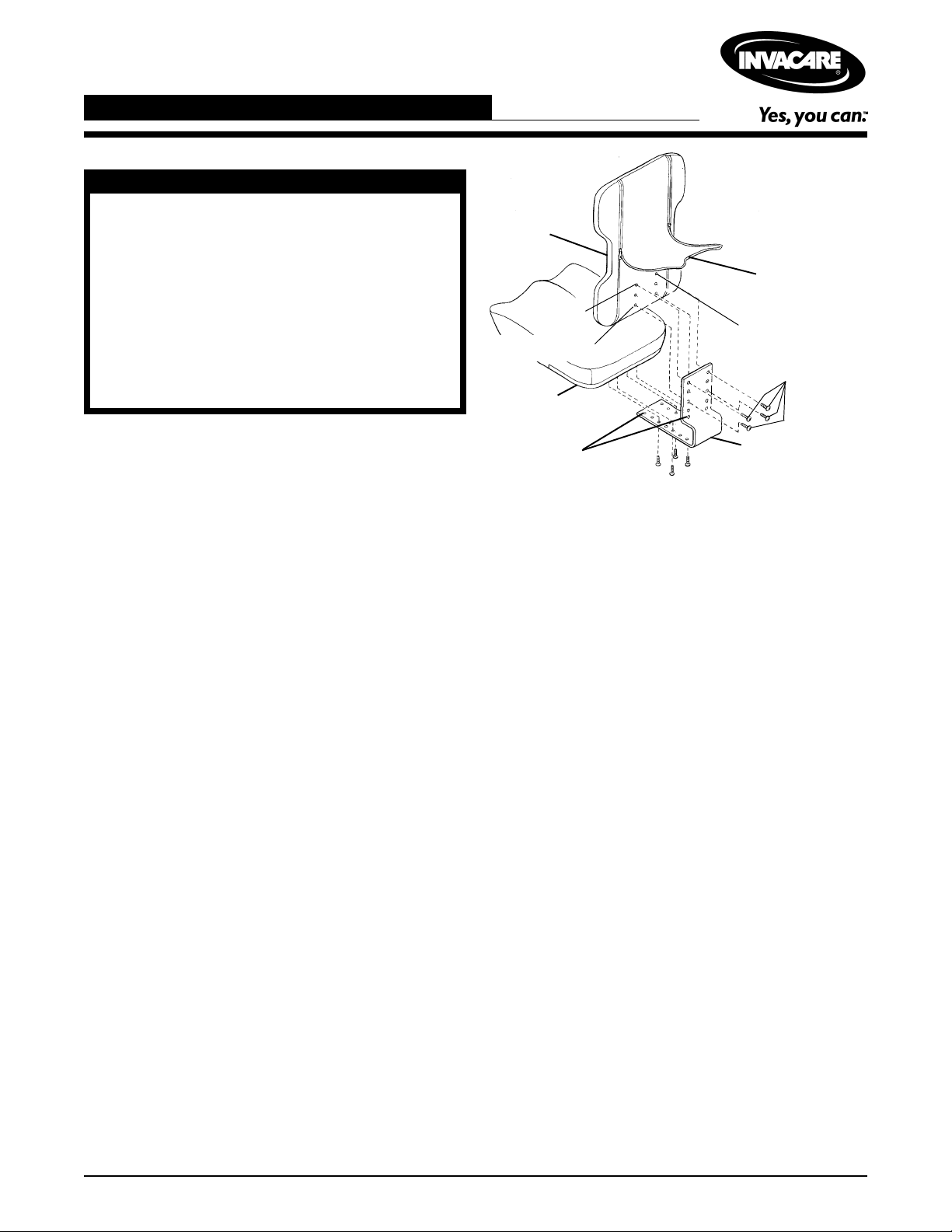
ATTACHING/ADJUSTING THE
FIXED GROWTH BRACKET
Curved
Back
Top Set
Bottom Set
Ulti-Mate
Base
Adjustment
holes
Center Panel
Six (6) T-nutted
mounting holes
Mounting
Screws
Growth Bracket
Attaching the Growth Bracket
NOTE: The growth bracket attaches to the Child/Junior
Size Curved Back only.
1. Remove the growth bracket and attaching hardware
from packaging.
2. Unzip center panel of the back cover, exposing the
six (6) T-nutted mounting holes.
NOTE: Make sure the growth bracket is positioned correctly. The flat portion of the growth bracket provides
depth adjustment for the Ulti-Mate Base. The angled
portion of the growth bracket provides height adjustment
for the Curved Back. See FIGURE 1.
3. Install four (4) of the mounting screws through the
holes in the growth bracket and into the back shell.
Securely tighten.
NOTE: On the curved back, the standard attachment
points are the top and bottom sets of holes. Refer to the
FIGURE 2-ATTACHMENT POINTS in this instruction
sheet for optional attachment points.
4. Install four (4) of the mounting screws through the
holes in the growth bracket and into the underside of
the Ulti-Mate Base. Securely tighten.
NOTE: On the Ulti-Mate Base, the standard attachment
points are the front and back sets of holes. Refer to the
FIGURE 2-ATTACHMENT POINTS in this instruction
sheet for optional attachment points.
5. If adjustment is required, refer to ADJUSTING THE
GROWTH BRACKET in this instruction sheet.
FIGURE 1 - ATTACHING/ADJUSTING THE
FIXED GROWTH BRACKET
Adjusting the Growth Bracket
(FIGURE 1)
ADJUSTING THE BACK HEIGHT.
1. If necessary, unzip center panel of the back cover.
2. Remove the four (4) mounting screws that secure
the growth bracket to the back.
3. Adjust the back up or down until the desired mounting position is obtained.
4. Reinstall the four (4) mounting screws through the
growth bracket and into the back shell. Securely
tighten. Refer to the FIGURE 2- ATTACHMENT
POINTS
optional attachment points.
5. Zip center panel of back cover closed.
in this instruction sheet for standard and
ADJUSTING THE ULTI-MATE BASE
DEPTH.
1. Remove the four (4) mounting screws that secure
the growth bracket to the Ulti-Mate Base.
2. Adjust the seat forward or back until the desired
mounting position is obtained.
3. Reinstall the four (4) mounting screws through the
growth bracket and into the seat. Securely tighten.
Refer to the FIGURE 2 - A TTACHMENT POINTS In
this instruction sheet for standard and optional attachment points.
1
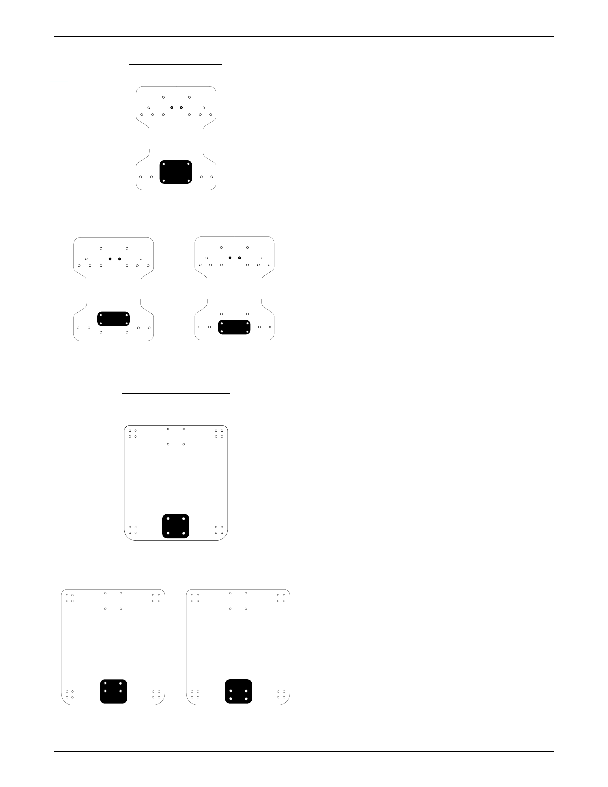
CURVED BACK
Top of Back
Standard
Bottom of Back
Top of Back
Option 1 Option 2
Bottom of Back
Bottom of Back
ULTI-MATE BASE
Front of Base
Top of Back
ATTACHING / ADJUSTING THE
ADJUSTABLE ANGLE GROWTH
BRACKET (FIGURE 3)
Attaching the Adjustable Angle Growth
Bracket
NOTE: The growth bracket attaches to the child/junior
sized curved back ONLY.
1. Remove the adjustable angle growth bracket and
attaching hardware from the packaging.
2. Unzip the center panel of the back cover, exposing
the six (6) T-nutted mounting holes.
NOTE: Make sure that the growth bracket is positioned
correctly. The flat portion of the adjustable angle bracket
growth bracket provides depth adjustment for the Ultimate base. The angled portion of the adjustable angle
bracket height adjustment for the curved back
(FIGURE 2).
3. Install four (4) of the mounting screws through the
slots in the adjustable angle growth bracket and into
the underside of the Ulti-mate base. Securely tighten.
NOTE: On the Ulti-mate base, the standard attachment
points are the front and rear four (4) holes. Refer to the
FIGURE 2 - ATTACHMENT POINTS in this instruction
sheet for optional attachment points.
4. Install two (2) of the mounting screws through the
slots on the adjustable angle growth bracket and
into the back shell. Securely tighten.
Standard
Rear of Base
Front of Base
Front of Base
Option 1 Option 2
Rear of Base
Rear of Base
FIGURE 2 - ATTACHMENT POINTS
NOTE: On the curved back, the standard attachment
points are the MIDDLE set of holes. Refer to the
FIGURE 2 - ATTACHMENT POINTS in this instruction
sheet for optional attachment points.
5. If adjustment is required, refer to ADJUSTING
THE GROWTH BRACKET in this instruction
sheet.
Adjusting the Growth Bracket
ADJUSTING THE BACK HEIGHT.
1. If necessary, unzip center panel of the back
cover.
2. Loosen the two (2) mounting screws that secure the growth bracket to the back.
3. Adjust the back up or down until the desired
mounting position is obtained.
4. Securely tighten the two (2) mounting screws.
2

5. If more adjustment is needed, the adjustment screws
can be completely removed, and the bracket set to
a NEW T-nutted hole location. Refer to the
FIGURE 2 - A TT ACHMENT POINTS
tion sheet for optional attachment points.
6. Zip center panel of back cover closed.
in this instruc-
ADJUSTING THE ULTI-MATE BASE
DEPTH.
1. If necessary, unzip center panel of the back cover.
2. Loosen the four (4) mounting screws that secure
the growth bracket to the Ulti-Mate Base.
3. Adjust the seat forward or back until the desired
mounting position is obtained.
4. Securely tighten the two (2) mounting screws.
5. If more adjustment is needed, the adjustment screws
can be completely removed, and the bracket set to
a NEW T-nutted hole location. Refer to the
FIGURE 2 - A TT ACHMENT POINTS
tion sheet for optional attachment points.
in this instruc-
ADJUSTING THE ANGLE OF THE BACK
(FIGURE 4).
NOTE: The adjustable angle growth bracket is infinitely
angle adjustable. The back-to-seat angle is set by the
location of the mounting points for the back in relation to
the base and by changing the hole positions of the adjustable angle back hooks.
1. Remove the two (2) attaching screws and nuts on
the adjustable angle back hooks.
2. Recline the back to the desired angle.
3. Align one (1) round hole and one (1) slotted hole on
the back L-bracket with two (2) of the holes on the
hook portion.
4. Reinstall the two (2) screws and nuts and securely
tighten.
Hook Portion
6. Zip center panel of back cover closed.
Top Mounting
Screws
Bottom Mounting
Screws
FIGURE 3 - ATT ACHING / ADJUSTING THE
ADJUSTABLE ANGLE GROWTH
BRACKET
Nuts
L-Bracket
Attaching Screws
FIGURE 4 - ADJUSTING THE ANGLE OF
THE BACK
3

LIMITED W ARRANTY
PLEASE NOTE: THE W ARRANTY BELOW HAS BEEN DRAFTED TO COMPL Y WITH FEDERAL LA W APPLICABLE TO
PRODUCTS MANUF ACTURED AFTER JUL Y 4, 1975.
This warranty is extended only to the original purchaser/user of our products.
This warranty gives you specific legal rights and you may also have other legal rights which vary from
state to state.
Invacare warrants its product to be free from defects in materials and workmanship for the
period of two (2) years of use by original purchaser. If within such warranty period any such
product shall be proven to be defective, such product shall be repaired or replaced, at Invacare's
option. This warranty does not include any labor or shipping charges incurred in replacement part
installation or repair of any such product. Invacare's sole obligation and your exclusive remedy under
this warranty shall be limited to such repair and/or replacement.
For warranty service, please contact the dealer from whom you purchased your Invacare
product. In the event you do not receive satisfactory warranty service, please write directly to
Invacare at the address on the next page. Provide dealer's name, address, model number, date of
purchase, indicate nature of the defect and, if the product is serialized, indicate the serial number.
Invacare Corporation will issue a return authorization. The defective unit or parts must be returned for
warranty inspection using the serial number, when applicable, as identification within thirty (30) days of
return authorization date. DO NOT return products to our factory without our prior consent. C.O.D.
shipments will be refused; please prepay shipping charges.
LIMIT ATIONS AND EXCLUSIONS: THE W ARRANTY SHALL NOT APPL Y TO PROBLEMS ARISING FROM NORMAL
WEAR OR F AILURE TO ADHERE TO THE ENCLOSED INSTRUCTIONS. IN ADDITION, THE FOREGOING W ARRANTY
SHALL NOT APPL Y TO SERIAL NUMBERED PRODUCTS IF THE SERIAL NUMBER HAS BEEN REMOVED OR DEFACED;
PRODUCTS SUBJECTED TO NEGLIGENCE, ACCIDENT, IMPROPER OPERA TION, MAINTENANCE OR STORAGE;
OR PRODUCTS MODIFIED WITHOUT INV ACARE'S EXPRESS WRITTEN CONSENT INCLUDING, BUT NOT LIMITED
TO: MODIFICA TION THROUGH THE USE OF UNAUTHORIZED PARTS OR A TT ACHMENTS: PRODUCTS DAMAGED
BY REASON OF REP AIRS MADE TO ANY COMPONENT WITHOUT THE SPECIFIC CONSENT OF INV ACARE; PRODUCTS DAMAGED BY CIRCUMST ANCES BEYOND INV ACARE'S CONTROL; PRODUCTS REPAIRED BY ANYONE
OTHER THAN ANAUTHORIZED INVACARE DEALER, SUCH EVALUATION SHALL BE SOLELY DETERMINED BY
INV ACARE.
THE FOREGOING W ARRANTY IS EXCLUSIVE AND IN LIEU OF ALL OTHER EXPRESS W ARRANTIES, IF ANY, INCLUDING THE IMPLIED WARRANTIES OF MERCHANTABILITY AND FITNESS FOR A PARTICULAR
PURPOSE.
IT SHALL NOT EXTEND BEYOND THE DURA TION OF THE EXPRESSED W ARRANTY PROVIDED HEREIN AND THE
REMEDY FOR VIOLA TIONS OF ANY IMPLIED W ARRANTY SHALL BE LIMITED TO REP AIR OR REPLACEMENT OF
THE DEFECTIVE PRODUCT PURSUANT TO THE TERMS CONT AINED HEREIN. INVACARE SHALL NOT BE LIABLE
FOR ANY CONSEQUENTIAL OR INCIDENT AL DAMAGES WHATSOEVER.
THIS W ARRANTY SHALL BE EXTENDED TO COMPL Y WITH STA TE/PROVINCIAL LA WS AND REQUIREMENTS.
Invacare Corporation www.invacare.com
USA Canada
One Invacare Way 5970 Chedworth Way Invacare and "Yes, you can" are trademarks of Invacare
Elyria, Ohio USA Mississauga, Ontario Corporation.
44036-2125 L5R 3T9, Canada © 2000 Invacare Corporation
800-333-6900 905-890-8838 Form No. 96-324 Part No. 1068857 Rev A (1) 7/00
 Loading...