

Page 1
9000 XDT TALL FORK/STEM CONVERSION KIT
Assembly, Installation and Operating Instructions
Kit Nos. 1070843 and 1075042
NOTE: This instruction sheet pertains to the following Kits:
1070843 (chrome), for wheelchairs built before 10/97, and
Kit No. 1075042 (chrome), for wheelchairs built after 10/97.
NOTE: Check all parts for shipping damage. If damage is
found, DO NOT use. Contact Carrier/Invacare for further
instructions.
SAFETY SUMMARY
The following recommendations are made for the
safe and proper installation and use of the 9000
XDT T all Fork/Stem Conversion Kit:
GENERAL WARNING
DO NOT assemble or use this equipment
without first reading and understanding this instruction sheet. If you are unable to understand the Warnings, Cautions or Instructions, contact a healthcare
professional, dealer or technical personnel if applicable before attempting to install this equipment otherwise, injury or damage may occur.
INSTALLATION WARNING
After ANY adjustments, repair or service and BEFORE use, make sure that all attaching hardware is
tightened securely.
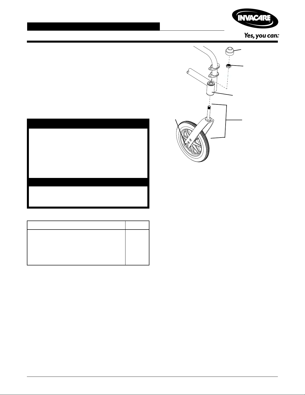
Dust Cover
Locknut
Caster Headtube
Hex Screw,
Washers and
Locknut
Front Caster
and Fork
FIGURE 1 - DISASSEMBLING THE EXISTING
FORK/STEM ASSEMBLY
DISASSEMBLING THE EXISTING
CASTER HEADTUBE ASSEMBLY
(FIGURE 2)
All Kits Include the Following:
Description Quantity
Flanged Bearing 2
Dust Cover 2
Locknut 2
Fork Assembly 2
Bottom Sleeve With Bearing 2
DISASSEMBLING THE EXISTING
FORK/STEM ASSEMBLY (FIGURE 1)
1. Remove and discard the dust cover.
2. Remove and discard the locknut that secures the fork
to the caster headtube.
3. Drop the front caster and fork out of the caster
headtube.
4. Remove the hex screw, washers and locknut that secures the front caster to the fork. Discard the fork.
NOTE: Front casters will be assembled to NEW fork.
5. Disassemble the existing caster headtube assembly.
Refer to DISASSEMBLING THE EXISTING CASTER
HEADTUBE ASSEMBL Y in this instruction sheet.
NOTE: There are two (2) different bottom bearing assemblies. Refer to FIGURE 2 to determine the proper bearing.
1. Place a punch through the opening in the
BOTTOM flanged bearing or assembly housing of
the caster headtube and position it against the side of
the TOP flanged bearing.
2. Using a rubber mallet, gently tap the punch while moving it from side-to-side until the TOP flanged bearing
is free from the caster headtube. Discard the TOP
flanged bearing.
3. Place a punch through the opening in the caster head
tube and and position it against the side of the BOTTOM flanged bearing or assembly housing.
4. Using a rubber mallet, gently tap the punch while moving t from side-to-side until the BOTTOM flanged bearing or assembly housing is free from the caster
headtube.
5. Repeat STEPS 1 through 4 for the opposite caster
headtube bearings.
6. Assemble the tall fork/stem assembly. Refer to AS-
SEMBLING THE T ALL FORK/STEM ASSEMBLY
in this instruction sheet.
1
Page 2
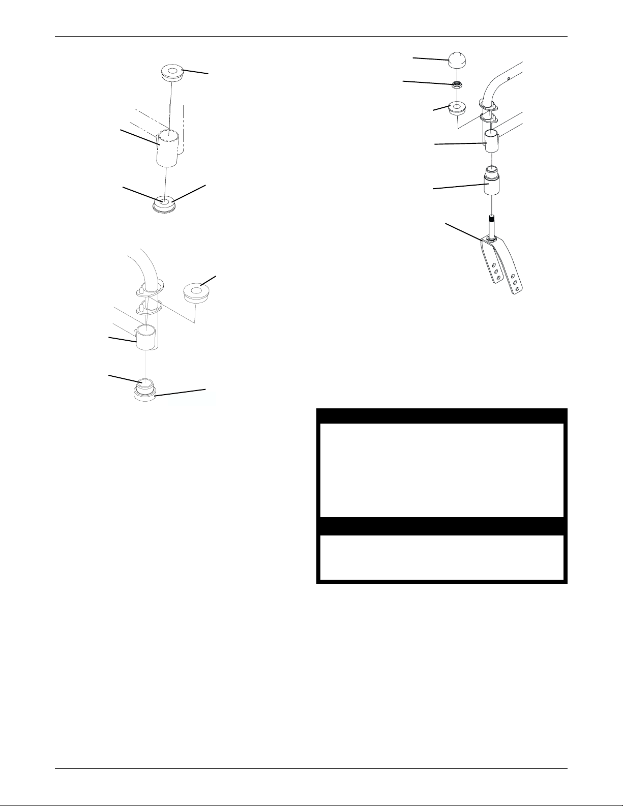
WHEELCHAIRS BUILT BEFORE 10/97
NEW Dust Cover
TOP Flanged
Bearing
Caster
Headtube
Opening
BOTTOM Flanged
WHEELCHAIRS BUILT AFTER 10/97
TOP Flanged
Bearing
Caster
Headtube
Opening
Assembly Housing
NEW Locknut
NEW Flanged Bearing
Caster Headtube
NEW Sleeve
Bottom With Bearing
Bearing
NEW Tall Fork/Stem Assembly
FIGURE 3 - REASSEMBLING THE TALL FORK/
STEM ASSEMBLY
REINSTALLING FRONT CASTERS
(FIGURE 4)
NOTE: Refer to the INSTALLATION WARNING in the
SAFETY SUMMARY section of this instruction sheet.
FIGURE 2 - DISASSEMBLING THE EXISTING
CASTER HEADTUBE ASSEMBLY
ASSEMBLING THE TALL FORK/
STEM ASSEMBLY (FIGURE 3)
NOTE: Refer to the INSTALLATION WARNING in the
SAFETY SUMMARY section of this instruction sheet.
1. Using a rubber mallet, gently tap the NEW flanged
bearing into the TOP of the caster headtube.
2. Using a rubber mallet, gently tap the NEW sleeve bottom with bearing into the BOTTOM of caster headtube.
3. Insert the NEW tall fork/stem assembly through the
bearings in the caster headtube.
4. Secure with the NEW locknut.
5. Repeat STEPS 1-4 for the opposite fork/stem
assembly.
NOTE: DO NOT install the NEW dust covers at this time,
as adjustments to the locknuts may be required later.
6. Install the casters onto the NEW tall fork/stem assemblies. Refer to REINST ALLING FRONT CASTERS
in this instruction sheet.
WARNINGS
Replacement of front caster tire or tube MUST be
performed by an authorized Invacare dealer or
qualified technician.
Make sure both front casters are positioned in the
same mounting hole BEFORE using the wheelchair
- otherwise, injury or damage may occur.
CAUTION
As with any vehicle, the wheels and tires should be
checked periodically for cracks and wear, and
should be replaced.
1. Position the front caster on the fork to the determined
mounting hole. Refer to CHANGING SEAT-TO-FLOOR
HEIGHT in 9000 Series Service Manual Part No.
1076155 to determine the proper front caster mounting
holes for caster size and seat-to-floor height.
2. Install the existing washers, hex screw and locknut.
Tighten securely.
3. Repeat STEPS 1-2 for the opposite front caster.
4. Reposition the rear wheels. Refer to REPOSITION-
ING THE REAR WHEELS in this instruction sheet.
2
Page 3

Fork
Locknut
C. Let the casters drop to the bottom of the arc
(the wheels should swing once to one-side, then
immediately rest in a straight downward position).
Hex Screw
Washer
Washer
Front Caster
FIGURE 4 - REINSTALLING FRONT CASTERS
REPOSITIONING THE REAR
WHEELS (FIGURE 5)
NOTE: When the 9000 XDT Tall Fork/Stem is installed
and a Tall Seat-to-Floor is desired, the rear wheel MUST
be repositioned in the BOTTOM Mounting Hole to avoid
excessive rear seat dump.
BOTTOM Mounting Hole
D. Adjust the locknuts according to the freedom of
the caster swing.
2. Test the wheelchair for maneuverability.
3. Readjust the locknuts if necessary, and repeat STEPS
1-2 until correct.
4. Snap the dust covers over the locknut and stem.
5. Install the wheel lock shoe extensions if necessary.
Refer to INSTALLING WHEEL LOCK SHOE EX-
TENSIONS in this instruction sheet.
INSTALLING WHEEL LOCK SHOE
EXTENSIONS (FIGURE 6)
NOTE: Refer to the INSTALLATION WARNING in the
SAFETY SUMMARY section of this instruction sheet.
NOTE: The wheel lock shoe extensions are to ensure that
the wheel lock engages properly and holds the wheelchair
in place. They are needed for chairs with U2222 rear wheels
in the tall configurartion. If this chair already has wheel
lock shoe extensions installed, do NOT replace. Refer to
Parts Book Form No. 95-137 for proper wheel lock shoe
extensions part numbers.
1. Place the wheel lock in the unlocked position.
FIGURE 5 - REPOSITIONING THE REAR WHEELS
1. Reposition rear wheels if necessary. Refer to REAR
WHEEL in 9000 Series Owner's Manual Part No.
1056953 and CHANGING SEAT-TO-FLOOR
HEIGHT in 9000 Series Service Manual Part No.
1076155.
2. After the rear wheel has been repositioned, perform
WHEELCHAIR MANEUVERABILITY. Refer to
WHEELCHAIR MANEUVERABILITY in this instruc-
tion sheet.
WHEELCHAIR MANEUVERABILITY
1. Properly tighten the caster journal system and guard
against flutter by performing the following check:
A. Tip the back of the wheelchair to the floor.
2. Loosen the two (2) set screws in the wheel lock shoe
extension.
3. Position the wheel lock shoe extension over the existing wheel lock shoe.
NOTE: Ensure the wedge end of the wheel lock shoe
extension is facing the rear wheel.
4. Securely tighten set screws.
5. Repeat STEPS 1-4 for the opposite wheel lock.
6. Adjust the wheel locks. Refer to ADJUSTING THE
PATIENT OPERA TED WHEEL LOCKS in this instruction sheet.
Wheel
Lock
Wheel
Lock Shoe
Set Screws
Wheel Lock
Shoe Extension
Wedge
End
B. Pivot both the forks and casters to the top of their
arc simultaneously.
FIGURE 6 - INSTALLING WHEEL LOCK SHOE SPACERS
3
Page 4

ADJUSTING THE PATIENT
OPERATED WHEEL LOCK (FIGURE 7)
NOTE: Refer to the INSTALLATION WARNING in the
SAFETY SUMMARY section of this instruction sheet.
NOTE: If wheels are pneumatic, before adjusting or replacing the wheel lock assemblies, ensure that the tires
are inflated to the recommended p.s.i. The recommended
tire pressure is located on the side wall of the tire.
1. Loosen the bolt and locknut that secure the wheel
lock assembly to the wheelchair frame.
Mounting
Positions
Bolt and Locknut
Wheel Lock
Handle
Wheelchair
Frame
Wheel
Lock
Shoe/
Shoe
Extension
2. Adjust the position of wheel lock until the measurement between the rear wheel and the wheel lock shoe
or shoe extension is between 5/32 and 5/16-inches.
NOTE: If a measurement between 5/32 and 5/16-inches
cannot be achieved, remove the bolt and locknut that
secure the wheel lock to the wheelchair and mount the
wheel lock in one (1) of two (2) mounting positions.
3. Securely tighten the bolt and locknut.
4. Engage the wheel lock and push it against the wheelchair to determine if the wheel lock engages the wheel
lock shoe enough to hold the wheelchair.
5. Repeat STEPS 1-4 until the wheel lock holds the
wheelchair.
6. Repeat STEPS 1-5 for the opposite wheel lock.
Wheel
Lock
5/32 and
5/16-inches
Rear
Wheel
FIGURE 7 - ADJUSTING THE PATIENT
OPERATED WHEEL LOCK
Invacare Corporation www.invacare.com
USA Canada
One Invacare Way 5970 Chedworth Way Invacare and "Yes, you can" are trademarks of Invacare
Elyria, Ohio USA Mississauga, Ontario Corporation.
44036-2125 L5R 3T9, Canada © 2000 Invacare Corporation
800-333-6900 905-890-8838 Form No. 97-196 Part No. 1075041 Rev A (1) 4/00
 Loading...