

MPR Recline Mechanism Kit - Model
6905A, 6907A, 6908A
Assembly, Installation and Operating Instructions
Kit No. 1124312, 1124313
SAVE THESE INSTRUCTIONS
NOTE: Check ALL parts for shipping damage. In case of shipping damage, DO NOT use. Contact
Carrier/Dealer for further instruction.
SAFETY SUMMARY
To ensure the safe installation, operation and use of the MPR Recline
Mechanism Kit, these instructions MUST be followed:
GENERAL WARNING
DO NOT install or use this equipment without first reading and understanding
these instructions. If you are unable to understand the Warnings, Cautions or
Instructions, contact a healthcare professional, dealer or technical personnel before
attempting to install this equipment - otherwise injury or damage may occur.
INSTALLATION WARNING
After ANY adjustments, repair or service and before use, make sure all attaching
hardware is tightened securely - otherwise injury or damage may occur.
Recline Mechanism Kit (Part No. 1124312) contains the following items:
DESCRIPTION QUANTITY
Recline Mechanism (Left and Right) 1 Pair
Footrest Guard 2
Recline Mechanism Hardware Kit (Part No. 1124313) contains the following items:
DESCRIPTION QUANTITY
Seat Mounting Bracket 2
Plug Button 4
1/4-20 x 1-1/2-inch Hex Head Screw 8
1/4-20 x 1-inch Hex Head Screw 8
1/4-20 x 1/2-inch Flange Head Screw 4
1/4-20 Locknut 10
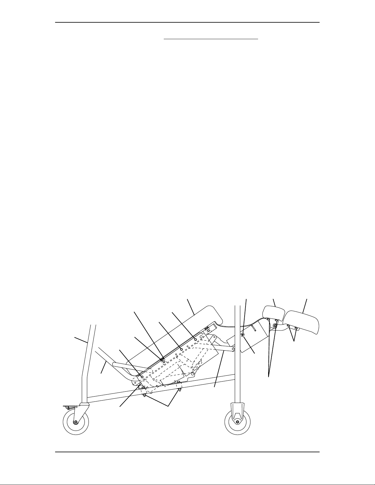
REPLACING RECLINE MECHANISM (FIGURE 1)
1. Engage wheel locks.
2. Remove the tray from recliner. Refer to STORING/REMOVING THE TRAY in the
Owner’s Manual, part number 54000M107.
3. Extend the footrest of the recliner.
For more information regarding Invacare products, parts, and services,
please visit: www.invacare.co
Part No. 1123851 1 MPR Recline Mechanism Kit
m
4. Remove the side panel. Refer to REPLACING THE SIDE PANEL in the Owner’s
Manual, part number 54000M107
5. Carefully tip recliner onto opposite side of recline mechanism to be replaced. Be
sure there are no obstructions on or around the floor before doing this.
6. Remove one (1) 1/4-20 x 3/4-inch pan head screw that secures the support tube to
recline mechanism.
7. Remove two (2) 1/4-20 x 1-inch hex head screws that secure the footrest cushion to
recline mechanism.
8. Remove two (2) 1/4-20 x 1/2-inch flange head screws that secure the center footrest
cushion to recline mechanism.
9. Remove four (4) bolts A, B, C and D that secure recline mechanism guard and the
recline mechanism to the seat frame.
NOTE: Ensure that the seat mounting bracket is secured by BOLT B during reinstallation.
10. Remove two (2) 1/4-20 x 1-1/2-inch hex head screws and 1/4-20 locknuts that secure
the recline mechanism to the base frame.
NOTE: Carefully support the recline mechanism while removing the last two (2) screws.
11. Position NEW recline mechanism, aligning mounting holes with holes in base frame
and seat frame.
12. Reassemble by reversing STEPS 4-10.
13. Place recliner in the upright position.
14. Repeat STEPS 4-13 to replace remaining recline mechanism.
15. Close the footrest.
16. Reinstall tray into the recliner frame.
Base
Frame
Seat
Frame
Seat Mounting
Bracket
Bolt B
Bolt A
Seat
Cushion
Bolt D
Bolt C
1/4-20 x 3/4-inch
Pan Head Screw
Recline
Mechanism
Center
Footrest
Cushion
1/4-20 x 1-inch
Support
Tube
1/4-20 x 1/2-inch
Flange Head
Hex Head Screw
Screw
Footrest
Cushion
Recline
Mechanism
Guard
1/4-20 x 1-1/2-inch
Hex Head Screw
and 1/4-20 Locknut
FIGURE 1- REPLACING RECLINE MECHANISM
MPR Recline Mechanism Kit 2 Part No. 1123851

REPLACING FOOTREST GUARD (FIGURE 2)
NOTE: Right and left sides are determined from the user’s seated position.
1. Engage wheel locks.
2. Extend the footrest of the recliner.
3. Carefully tip the recliner onto the right side. Be sure there are no obstructions on or
around the floor before doing this.
4. Remove mounting bolt from support tube and cut tie wrap.
5. Remove existing footrest guard from recliner.
6. Install NEW footrest guard around the footrest frame as shown in DETAIL “A” of
FIGURE 2.
NOTE: Footrest guard needs to be folded in two (2) locations so it will wrap entirely around the
upper frame. Refer to the scored lines on the guard to determine where the folds should be.
7. Once folded, align the two (2) mounting holes of the footrest guard with the
mounting hole in the upper footrest frame as shown in DETAIL “B” in FIGURE 2.
8. Using the mounting bolt, secure the footrest guard and upper frame to the support tube.
CAUTION
DO NOT overtighten tie wrap during installation, otherwise the guard may
buckle or deform.
WARNING
Tie wrap should be installed with the excess material and tie wrap head
located on the interior side of the footrest assembly. Failure to do so may
result in serious injury.
9. With a tie wrap, secure the footrest guard to the upper side frame as shown in
DETAIL “B” in FIGURE 2.
NOTE: If necessary, trim excess tie wrap to prevent binding and pinching.
10. Place recliner in the upright position. Close the footrest. If binding or pinching of
footrest guard occurs, call Invacare at the number listed on the back cover.
11. Carefully tip recliner onto the left side. Be sure there are no obstructions on or
around the floor before doing this.
12. Repeat STEPS 4-10 to install remaining footrest guard.
Part No. 1123851 3 MPR Recline Mechanism Kit

Footrest Guard
Mounting Holes
Support Tube
(Interior Side)
DETAIL “A”
Mounting Bolt
Scored Lines
Tie Wrap
Footrest
DETAIL “B” - SIDE VIEW
Tie Wrap
(STEP 9)(STEP 9)
(STEP 9)
(STEP 9)(STEP 9)
Mounting Bolt
(STEP 7)(STEP 7)
(STEP 7)
(STEP 7)(STEP 7)
Guard
Upper Frame
Position the Tie Wrap
such that head is on
interior of Footrest Guard
FIGURE 2 - REPLACING FOOTREST GUARD
Upper Frame
DO NOT use lower
frame for tie wrap.
Footrest Guard
Invacare Corporation www.invacare.com
USA Canada
One Invacare Way 570 Matheson Blvd E Unit 8 Invacare is a registered trademark of
Elyria, Ohio USA Mississauga Ontario Invacare Corporation.
44036-2125 L4Z4G4 Canada Yes, you can. is a trademark of Invacare
800-333-6900 800-668-5324 Corporation.
© 2004 Invacare Corporation
Part No. 1123851 Rev A - 3/04
 Loading...