

Page 1
Installing Cover Guards for MPR Clinical Recliners
Assembly, Installation and Operating Instructions
Kit # 1102816 for Model Nos. 6905A, 6907A, 6908A
SAVE THESE INSTRUCTIONS
NOTE: Check all parts for shipping damage, in case of damage, DO NOT use. Contact Carrier/Invacare
for further instructions.
SAFETY SUMMARY
To ensure the safe and proper installation and use of footrest and scissor mechanism guards,
these instructions MUST be followed:
GENERAL WARNING
DO NOT install this equipment without first reading and understanding this
instruction sheet and the Invacare Mobile Recliners Manual, part number
54000M107. If you are unable to understand the warnings, cautions and
instructions, contact a healthcare professional, dealer or technical personnel
if applicable, before attempting to install this equipment - otherwise, injury
or damage may occur.
INSTALLATION WARNING
After ANY adjustments, repair, or service and BEFORE use, make sure that all
attaching hardware is tightened securely.
Description Quantity
Footrest Cover 2
Mechanism Cover 2
Tie Wrap 2
INSTALLING FOOTREST GUARD AND SCISSOR
MECHANISM GUARD
FOOTREST GUARD (FIGURE 1)
NOTE: Right and left sides are determined from the users seated position.
1. Engage wheel locks.
2. Extend the footrest of the recliner.
3. Carefully tip the recliner onto the right side. Be sure there are no obstructions on or
around the floor before doing this.
4. Remove mounting bolt from support tube as shown in DETAIL A in FIGURE 1.
5. Install footrest guard around the footrest frame as shown in DETAIL A in FIGURE 1.
NOTE: Footrest guard needs to be folded in two (2) locations so it will wrap entirely around the upper
frame. Refer to the scored lines on the guard to determine where the folds should be.
6. Once folded, align the two (2) mounting holes of the footrest guard with the mounting
hole in the upper frame as shown in DETAIL A in FIGURE 1.
7. Using the mounting bolt, secure the footrest guard and upper frame to the support tube
as shown in DETAIL A in FIGURE 1.
1
Page 2
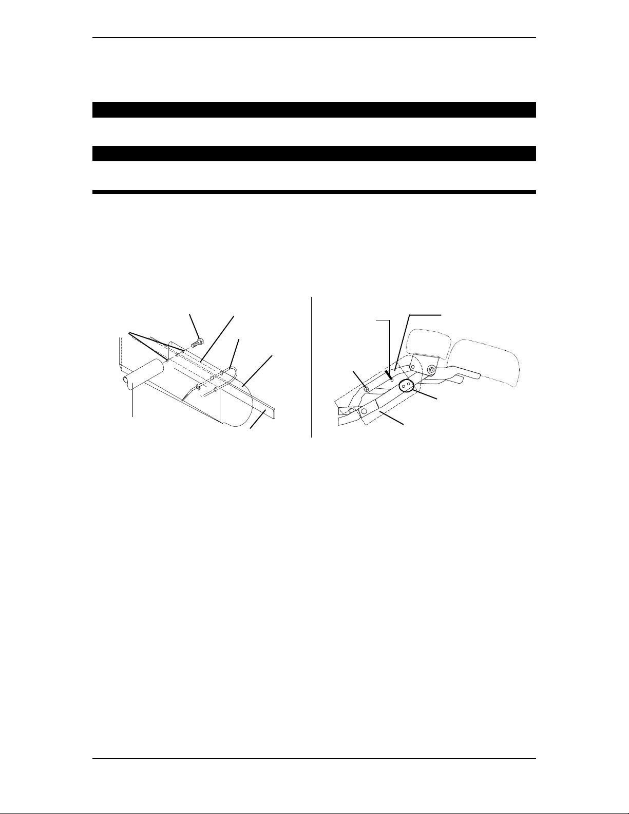
8. With a tie wrap, secure the footrest guard to the upper side frame as shown in DETAIL
B in FIGURE 1.
NOTE: If necessary, trim excess tie wrap to prevent binding and pinching.
CAUTION
When installing tie-wrap, pull tie wrap tight but not too tight causing the
guard to buckle or deform.
WARNING
Tie wrap should be installed with the excess located on the interior side of the
footrest assembly. Failure to do so may result in serious injury.
9. Place chair in the upright position. Close the footrest. If binding or pinching of footrest
guard occurs, call Invacare at the number listed on the back cover.
10. Carefully tip recliner onto the left side. Be sure there are no obstructions on or around
the floor before doing this.
11. Repeat STEPS 4-9 to install remaining footrest guard.
Mounting
Holes
Support Tube
(Interior Side)
DETAIL A
Mounting Bolt
Upper Frame
Scored Lines
Tie Wrap
Footrest
Guard
Mounting
DETAIL B - Side View
Tie Wrap
Bolt
Footrest Guard
Upper Frame
DO NOT use lower
frame for tie wrap.
FIGURE 1 - INSTALLING FOOTREST GUARD
INSTALLING SCISSOR MECHANISM GUARD (FIGURES 2 AND 3)
NOTE: Right and left sides are determined from the user's seated position.
1. Engage wheel locks.
2. Carefully tip recliner onto the right side. Be sure there are no obstructions on or around
the floor before doing this.
NOTE: On model 6905A chairs manufactured before 04/01/02, the side panel was secured with plastic
rivets. Replacement panel kit # 1109705 is required to install. Contact Invacare Dealer/Provider for
more information and ordering.
3. Perform one (1) of the following:
A. FOR MODEL 6905A MANUFACTURED BEFORE 04/01/2002 - remove
the seven (7) rivets securing the side panel to the recliner frame. Refer to
DETAIL A in FIGURE 2.
B. FOR MODEL 6905A MANUFACTURED AFTER 04/01/2002 - remove the
eleven (11) bolts securing the side panel to the recliner frame. Refer to DETAIL
"B in FIGURE 2.
C. FOR MODELS 6907A AND 6908A - remove four (4) bolts securing the side
panel to the wheelchair frame. Refer to DETAIL "C" in FIGURE 2.
2
Page 3

DETAIL A - MODEL 6905A
MANUFACTURED BEFORE
04/01/2002
Recliner Frame
Rivets
Rivets
DETAIL B - MODEL 6905A
MANUFACTURED AFTER
04/01/2002
Recliner Frame
Bolts
Bolts
Rivets
NOTE: Side panel not shown to show rivet
locations.
Bolts
DETAIL C - REMOVING SIDE COVER MODELS 6907A AND 6908A
Bolts
FIGURE 2 - INSTALLING THE SCISSOR MECHANISM GUARD
4. Remove four (4) existing bolts A, B, C and D from side frame as shown in
FIGURE 3.
5. Position scissor mechanism guard against the side frame with the folded edge down.
Refer to FIGURE 3.
6. Align holes of scissor mechanism guard with holes on side frame.
7. Secure scissor mechanism guard to side frame with existing bolts A, B, C, and D.
8. Perform one (1) of the following:
A. FOR MODEL 6905A BUILT BEFORE 04/01/2002 - Install new side panel
with kit no. 1109705 and using instruction sheet no. 1109704.
B. FOR MODEL 6905A BUILT AFTER 04/01/2002 - Secure the side cover to
the recliner frame with the eleven (11) bolts. Refer to DETAIL B in FIGURE 2.
C. FOR MODELS 6907A, 6908A - Secure the side cover to the recliner frame
with the four (4) bolts. Refer to DETAIL "C" in FIGURE 2.
3
Page 4

9. Place chair in the upright position.
10. Close the footrest.
NOTE: If binding or pinching of footrest guard occurs, call Invacare at the number listed below.
11. Carefully tip recliner onto the left side. Be sure there are no obstructions on or around the
floor before doing this.
12. Repeat STEPS 3-11 to install remaining scissor mechanism guard.
SIDE VIEW
REAR OF
CHAIR
Seat Cushion
FRONT OF
CHAIR
Side Frame
DO NOT
Footrest
remove this bolt
Bolt A
Bolt B
Bolt C Bolt D
Scissor Mechanism Guard
NOTE: Some detail removed for clarity.
FIGURE 3 - INSTALLING THE SCISSOR MECHANISM GUARD
Invacare Corporation www.invacare.com
USA
One Invacare Way Invacare is a registered trademark of
Elyria, Ohio USA Invacare Corporation.
44036-2125 Yes, you can. is a trademark of Invacare
800-333-6900 Corporation.
© 2002 Invacare Corporation
Part No. 1109697 Rev B - 7/02
 Loading...