

International comfort products PGX3 Series, PGX336060, PGX336080, PGX336100, PGX342080 Installation Instructions Manual
...
Printed in U.S.A.
509 01 2601 02 8−13−09
PACKAGED GAS / ELECTRIC UNITS
Installation Instructions
PGX3 Series
3 Phase
Code: PGX3
International Comfort Products, LLC
Lewisburg, TN. 37091
TABLE OF CONTENTS
UNIT DIMENSIONS 2 - 3. . . . . . . . . . . . . . . . . . . . . . . . . . . . . . . . . . . . . .
SAFE INSTALLATION REQUIREMENTS 4. . . . . . . . . . . . . . . . . . . . . . . . .
LOCATING THE UNIT 5. . . . . . . . . . . . . . . . . . . . . . . . . . . . . . . . . . . . . . .
CLEARANCES 5. . . . . . . . . . . . . . . . . . . . . . . . . . . . . . . . . . . . . . . . . . . .
INSTALLATION 5. . . . . . . . . . . . . . . . . . . . . . . . . . . . . . . . . . . . . . . . . . . .
GROUND LEVEL INSTALLATION 5. . . . . . . . . . . . . . . . . . . . . . . . . . . . . .
ROOFTOP INSTALLATION 5. . . . . . . . . . . . . . . . . . . . . . . . . . . . . . . . . . .
HOISTING 6. . . . . . . . . . . . . . . . . . . . . . . . . . . . . . . . . . . . . . . . . . . . . . . .
DOWNFLOW CONVERSION 6. . . . . . . . . . . . . . . . . . . . . . . . . . . . . . . . . .
HEATING VENT ASSEMBLY 6. . . . . . . . . . . . . . . . . . . . . . . . . . . . . . . . . .
CONDENSATE DRAIN 7. . . . . . . . . . . . . . . . . . . . . . . . . . . . . . . . . . . . . . .
PRE-EXISTING COMMON VENT CHECK 7. . . . . . . . . . . . . . . . . . . . . . . . .
GAS SUPPLY AND PIPING 7. . . . . . . . . . . . . . . . . . . . . . . . . . . . . . . . . . .
ORIFICES 8. . . . . . . . . . . . . . . . . . . . . . . . . . . . . . . . . . . . . . . . . . . . . . .
ELECTRICAL WIRING 9. . . . . . . . . . . . . . . . . . . . . . . . . . . . . . . . . . .
DUCTWORK 11. . . . . . . . . . . . . . . . . . . . . . . . . . . . . . . . . . . . . . . . .
FILTERS 11. . . . . . . . . . . . . . . . . . . . . . . . . . . . . . . . . . . . . . . . . . . .
AIRFLOW ADJUSTMENT 12. . . . . . . . . . . . . . . . . . . . . . . . . . . . . . .
START-UP PROCEDURES 13. . . . . . . . . . . . . . . . . . . . . . . . . . . . . .
GAS PRESSURES 14. . . . . . . . . . . . . . . . . . . . . . . . . . . . . . . . . . . . .
HEATING START-UP PROCEDURES 14. . . . . . . . . . . . . . . . . . . . . .
OPERATION 16. . . . . . . . . . . . . . . . . . . . . . . . . . . . . . . . . . . . . . . . .
MAINTENANCE 16. . . . . . . . . . . . . . . . . . . . . . . . . . . . . . . . . . . . . . .
INSPECTION AND CLEANING 17. . . . . . . . . . . . . . . . . . . . . . . . . . . .
COMPONENT LOCATION 18. . . . . . . . . . . . . . . . . . . . . . . . . . . . . . .
RIGGING 19. . . . . . . . . . . . . . . . . . . . . . . . . . . . . . . . . . . . . . . . . . .
WIRING DIAGRAMS 20 - 23. . . . . . . . . . . . . . . . . . . . . . . . . . . . . . . .
2
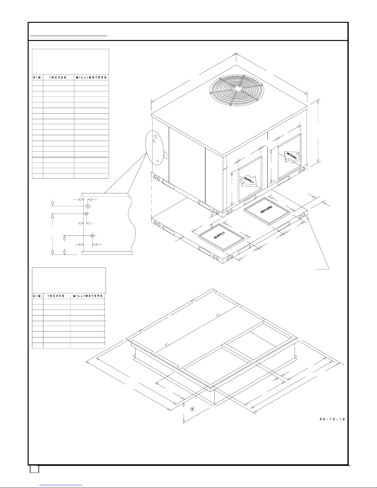
A32−1/2 826
B47−3/8 1203
C47−3/8 1203
D3−1/8 79
E11−1/8 283
F 12 306
G14−1/4 363
H14−1/4 363
I 12 306
J 4 102
K 3/4 & 1 19 & 25
L4−1/4 108
M4−3/8 111
N14−1/2 368
P12−1/4 311
Q12−1/8 308
R14−1/4 363
S12−1/4 318
COMBINATION GAS/
ELECTRIC UNITS
‘‘B’’ Chassis
(47
3
/8 x 473/8)
ROOF CURB
for units in
‘‘B’’ Chassis
(47
3
/8 x 473/8)
Units in ‘‘B’’ Chassis Configuration
PGX336
Units in ‘‘B’’ Chassis Configuration
PGX336
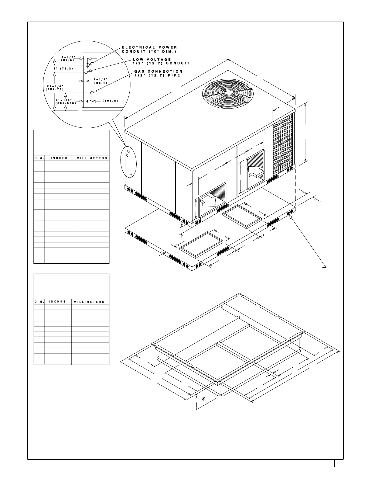
ELECTRICAL
POWER
LOW VOLTAGE
1/2” (12.7) CONDUIT
GAS CONNECTION
1/2” (12.7) PIPE
CONDUIT (”K” DIM.)
2−1/2”
(63.5)
3” (76.2)
1−1/2”
(38.1)
21−1/4”
(539.75)
11−1/8”
(282.575)
4”
(101.6)
”G”
”F”
”H”
”K”
’D”
”E”
”C”
”B”
”A”
”C”
”B”
”A”
”D”
”G”
”E”
”I”
”H”
”F”
”L”
”J”
”N”
”R”
”M”
”S”
”Q”
”P’’
A42−3/4 1086
B39−3/4 1010
C 18 457
D 18 457
E3−3/4 95
F42−3/4 1086
G39−3/4 1010
H 18 457
K* 14 356
‘‘B’’ CHASSIS UNIT DIMENSIONS
1. Unit Dimensions
Unit Base shown separately to
illustrate bottom of duct openings.
* Roof curbs are also available in 8” (203) and 24” (610) heights (K Dimensions).
COMBINATION GAS/
ELECTRIC UNITS
‘‘C’’ Chassis
(47
3
/8 x 73)
ROOF CURB
for
‘‘C’’ Chassis
(47
3
/8 x 73)
Units in ‘‘C’’ Chassis Configuration
PGX342−60
”C”
”B”
”A”
”I”
”E”
”G”
”D”
”F”
”J”
”H”
”L”
”N”
”R”
”S”
”Q”
”P”
”M”
SUPPLY
RETURN
”G”
”F”
”H”
”K”
’D”
”E”
”C”
”B”
”A”
”J”
”I”
”T”
A 36 914
B47−3/8 1203
C 73 1354
D4−5/8 117
E 15 361
F 12 307
G18−3/4 476
H18−3/4 476
I 12 306
J 4 102
K 1 & 1−1/4 25 & 31
L4−1/4 108
M5−1/4 133
N12−1/4 311
P 19 483
Q 15 381
R 19 483
S12−1/4 318
T16−7/8 429
A67−3/4 1721
B64−3/4 1645
C 23 584
D 23 584
E2−1/2 64
F42−3/4 1086
G39−3/4 1010
H 23 584
I 12 305
J 12 305
K* 14 356
‘‘C’’ CHASSIS UNIT DIMENSIONS
Unit Base shown separately to
illustrate bottom of duct openings.
* Roof curbs are also available in 8” (203) and 24” (610) heights (K Dimensions).
3
4
2. SAFE INSTALLATION REQUIREMENTS
Installation and servicing of air−conditioning equipment can
be hazardous due to system pressure and electrical
components. Only trained and qualified personnel should
install, repair, or service air−conditioning equipment.
Untrained personnel can perform basic maintenance
functions of cleaning coils and filters. All other operations
should be performed by trained service personnel. When
working on air−conditioning equipment, observe
precautions in the literature, tags, and labels attached to the
unit, and other safety precautions that may apply.
Follow all safety codes. Wear safety glasses and work
gloves. Use quenching cloth for unbrazing operations.
Have fire extinguisher available for all brazing operations.
FIRE, EXPLOSION, ELECTRICAL SHOCK, AND
CARBON MONOXIDE POISON HAZARD
Improper installation, adjustment, alteration, service,
maintenance, or use can cause carbon monoxide
poisoning, fire, or an explosion which could result in
personal injury or unit damage. Consult a qualified
installer, service agency, or gas supplier for information
or assistance. The qualified installer or agency must use
only factory−authorized kits or accessories when
modifying this product.
!
FIRE, EXPLOSION, ELECTRICAL SHOCK, AND
CARBON MONOXIDE POISON HAZARD
Failure to follow this warning could result in personal
injury, death and/or property damage.
Before performing service or maintenance operations
on unit, turn off gas supply to unit. Then turn off unit main
power switch and install lockout tag.
!
Recognize safety information. This is the safety−alert
symbol . When you see this symbol in instructions or
manuals, be alert to the potential for personal injury.
Understand the signal words DANGER, WARNING,
CAUTION, and NOTE. These words are used with the
safety−alert symbol. DANGER identifies the most serious
hazards which will result in serious injury or death.
WARNING signifies a hazard which could result in serious
injury or death. CAUTION is used to identify unsafe
practices which may result in minor personal injury or
product and property damage. NOTE is used to highlight
suggestions which will result in enhanced installation,
reliability, or operation.
These instructions cover minimum requirements and
conform to existing national standards and safety codes. In
some instances, these instructions exceed certain local
codes and ordinances, especially those that may not have
kept up with changing residential construction practices.
We require these instructions as a minimum for a safe
installation.
FIRE, EXPLOSION, ELECTRICAL SHOCK, AND CARBON
MONOXIDE POISON HAZARD
!
Failure to carefully read and follow all instructions in this
manual could result in furnace malfunction, property
damage, personal injury and/or death.
Installation or repairs made by unqualified persons can
result in hazards to you and others. Installation MUST
conform with local building codes or, in the absence of
local codes, with the National Fuel Gas Code NFPA
54−2005/ANSI Z223.1−2005 and the National Electrical
Code NFPA70−2005 or in Canada the National Standard
CAN/CGA B149−1 and CSA C.22.1 − Canadian Electrical
Code Part 1.
The information contained in this manual is intended for
use by a qualified service technician familiar with safety
procedures and equipped with the proper tools and test
instruments.
SAFETY CONSIDERATIONS
• Use only with type of gas approved for this unit. Refer to
unit rating plate.
• Install this unit only in a location and position as specified
in section 3 of this manual.
• Never test for gas leaks with an open flame. Use a commercially available soap solution made specifically for the
detection of leaks to check all connections, as specified in
section 5.
• Always install unit to operate within the unit’s intended
temperature−rise range with a duct system, which has an
external static pressure within the allowable range, as
specified in section 9. Refer to unit rating plate for the allowable external static pressures.
• All connecting ductwork to the unit (supply and return)
must be sealed to the unit casing as specified in section 7.
• Do NOT use this furnace as a construction heater.
• Check to see that filters are installed correctly and are the
proper type an size.
NOTE: It is the personal responsibility and obligation of the
customer to contact a qualified installer to ensure that the
installation is adequate and conforms to governing codes
and ordinances.
UNIT SAFETY
CAUTION
!
Failure to follow this caution may reduce unit reliability.
It is recommended that a qualified service technician
check the heat exchanger integrity every two (2) years,
after the first four (4) years of operation.
INTRODUCTION
The PGX3 unit is a fully self−contained, combination
Category I gas heating/electric cooling unit designed for
outdoor installation (See pages 2 and 3 for unit
dimensions). All unit sizes have return and discharge
openings for both horizontal and downflow configurations,
and are factory−shipped with all downflow duct openings
covered.
Units may be installed either on a rooftop, cement slab, or
directly on the ground if local codes permit.
!
5
Models with a ”1” in the twelfth position of the model number
are dedicated Low NOx units designed for California
installations. The emissions of these models do not exceed
40 nanograms of nitrogen oxide emissions per joule of heat
output as shipped from the factory, and must be installed in
California Air Quality Management Districts or any other
regions in North America where a Low NOx rule exists.
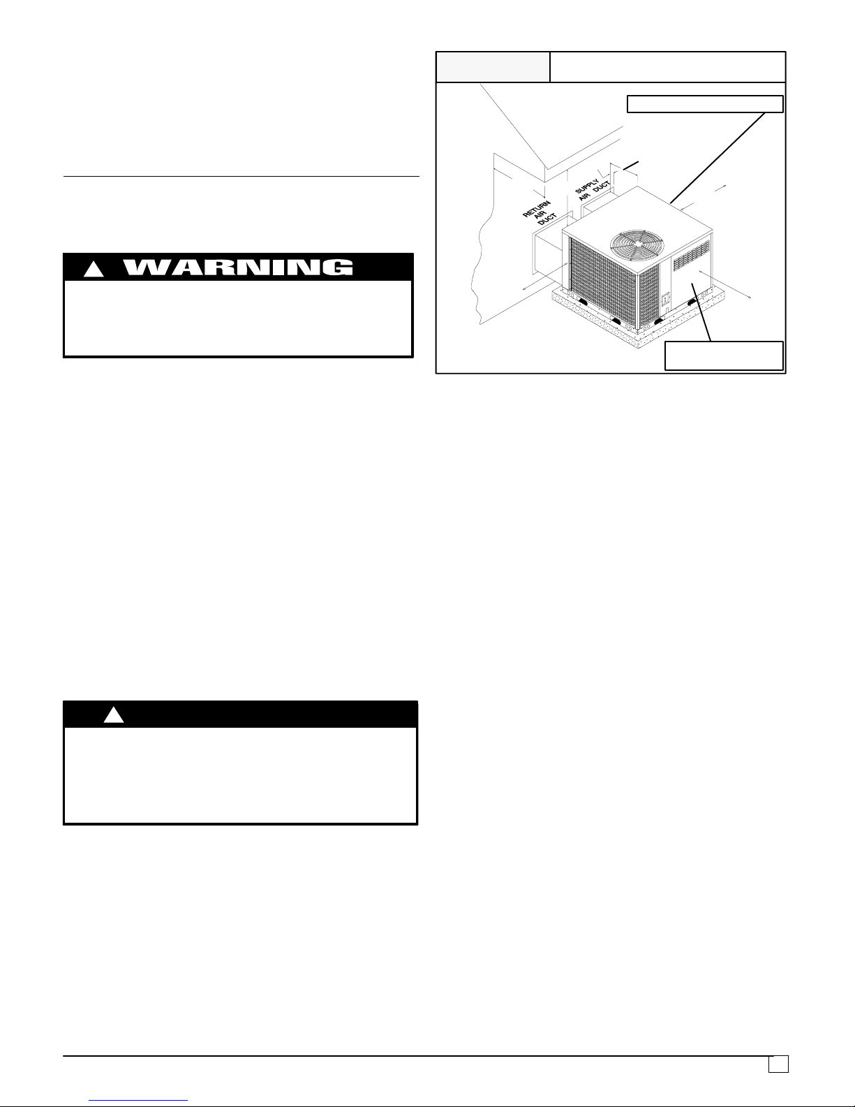
3. LOCATING THE UNIT
ACCESS PANELS
See Figure 1 for a general view of unit and location of
access panels.
CARBON MONOXIDE POISONING HAZARD.
!
Failure to follow this warning could result in personal
injury and/or death.
Keep blower door closed.
CLEARANCES
The location MUST allow for minimum clearances and
should not be adjacent to a patio or other area where the
unit’s operating sound level might be objectionable. The
combustion air inlet openings MUST not be obstructed (see
Figure 1). In addition, local codes MUST be observed.
NOTE: Units with available filter racks
( 3 to 5 ton), need a
26″ minimum clearance at side of unit for removal of filters.
See chart below if unit is going to be placed near
combustible construction or materials.
While minimum clearances are acceptable for safety
reasons, they may not allow adequate air circulation around
the unit for proper operation in the cooling mode. Whenever
possible, it is desirable to allow additional clearance,
especially around the condenser inlet and discharge
openings.
Do NOT install the unit in a location that will permit
discharged air from the condenser to recirculate to the
condenser inlet.
Do NOT operate unit in a corrosive atmosphere
containing chlorine, fluorine, or any other corrosive
chemicals.
CAUTION
!
UNIT DAMAGE HAZARD
Failure to follow this caution may result in shorten life
of unit components.
Minimum Clearances to Combustible Construction
Furnace Plenum 2″ . . . . . . . . . . . . . . . . . . . . . . . . . . . . . . . . . . . . .
Duct Side 2″. . . . . . . . . . . . . . . . . . . . . . . . . . . . . . . . . . . . . . . . . . .
Condenser Inlet 30″ . . . . . . . . . . . . . . . . . . . . . . . . . . . . . . . . . . .
Blower Service (Side) 30″ . . . . . . . . . . . . . . . . . . . . . . . . . . . . . .
Control Service Side
(Front Combustion Air Inlet) 30″ . . . . . . . . . . . . .
Clearance between 3 Ft. Overhang
and Top of Unit 30″ . . . . . . . . . . . . . . . . . . . . . . . .
Combustible Base
(Wood or Class A, B or C
roof covering material) 0″. . . . . . . . . . . . . . . . . . . .
FIGURE 1
Minimum Clearances and Access Panels
(B Chassis Shown)
Burner Compartment
Panel
Blower Compartment Panel
80−00−01
Internal Filter Access
from Burner Compartment Side
26’’ (C Chassis Units)
30’’
30’’
C Chassis − 6’’
30’’
30’’
36’’
2’’
B Chassis − 2’’
INSTALLATION
NOTICE
Unit will NOT operate properly unless it is installed
level front to rear and side to side. The slope MUST NOT
be greater than
1
/8″ per foot (10mm per meter). For side
to side leveling, the drain side MUST always be lower.
Ground Level Installation
Ground level platform requirements:
− The unit MUST be situated to provide safe access for
servicing.
− Platform may be made of either concrete or pressure
treated wood and MUST be level and strong enough to
support unit weight.
− Position platform separate from building foundation.
− Install in well−drained area, with top surface of platform
above grade level.
− Platform must be high enough to allow for proper
condensate trap installation and drainage. See
FIGURE 4 and associated text for more information
about condensate drainage.
Rooftop Installation
Rooftop platform requirements:
− The unit MUST be situated to provide safe access for
servicing.
− The existing roof structure MUST be adequate to
support the weight of the unit or the roof MUST be
reinforced.
Check the weight of the unit in relation to the roof
structure and local building codes or ordinances and
reinforce roof structure if necessary. See the last page
of this manual for unit weights.
− Support for the unit MUST be level and strong enough
to carry unit weight. The support may consist of a
platform or a combination of platform and roof beams or
curb.
− See Hoisting section for hoisting instructions.
HOISTING
NOTE: All access panels MUST be secured in place before
6
hoisting.
The unit should be hoisted with two lifting slings. Attach the
slings to rigging shackles that have been hooked through
holes in the base rail.
Two spreader bars MUST be placed on top of the unit to
protect the unit from damage from the pressure exerted by
the slings. Make sure that all equipment is adequate to
handle the weight of the unit and that the slings will not allow
the unit to shift.
Refer to FIGURE 18 on the back cover of this manual for
illustrated rigging instructions and weight chart.
DOWNFLOW CONVERSION
NOTE: In downflow applications with roof curbs or jack
stands, the center rail under the unit must be removed. The
center rail is attached to the base rail with screws.
These units are adaptable to downflow use. To convert to
downflow use, follow these steps:
1. Remove the blockoff plates found in the return air
compartment and the supply air compartment.
NOTE: Blockoff plate in the supply air compartment only
contains one screw. If reinstalling plate, back part of plate
MUST fit into mating dimples on flange. To reinstall, slant
plate into dimples, then put plate into position and fasten
with screw.
FIGURE 2
Heating Vent Assembly
Screws for
‘‘B’’ Chassis
(47
3
/8 x 473/8)
Screw for
‘‘C’’ Chassis
(47
3
/8 x 73)
2. Install the removed plates on the horizontal return and
supply air openings.
3. Install roof curb on the building. Be sure to follow all
directions included with curb and all applicable building
codes in your installation. See page 2 or 3 for
appropriate roof curb to use.
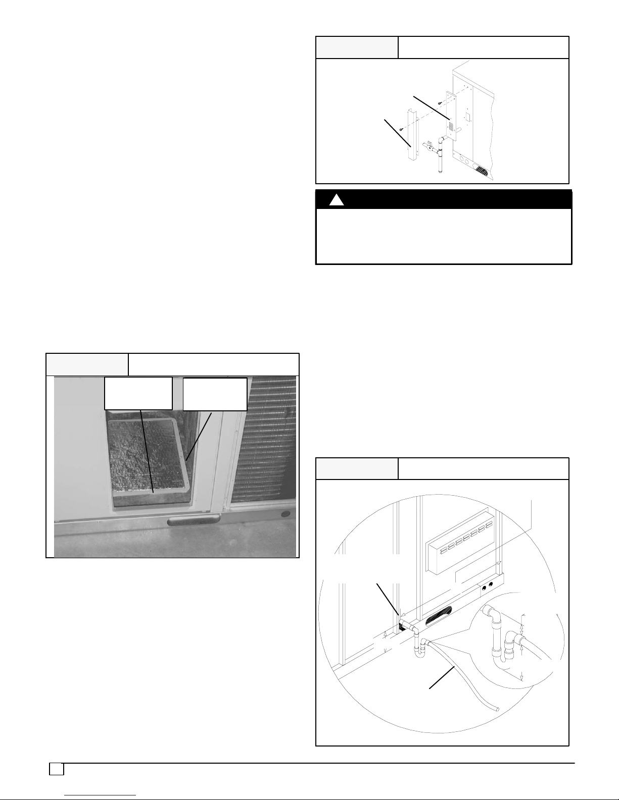
Heating Vent Assembly
The flue cover is packed with installation screws in the
return air compartment. Refer to FIGURE 3 and assemble
as shown.
FIGURE 3
Heating Vent Assembly
Flue Support
(Shipped mounted to unit)
Flue Cover
UNIT DAMAGE
CAUTION
!
Do not operate the unit without the vent assembly
installed.
Failure to follow this caution may result in unit
damage.
Condensate Drain
The condensate drain outlet is a
3
/4″ (19.1mm) female PVC
connection located at the bottom of the unit to the right of the
filter access panel (see FIGURE 4).
The circulating blower creates a negative pressure on the
condensate drain line that can prevent the condensate from
draining properly. To combat this negative pressure, a field
supplied condensate trap that will allow a standing column
of water of at least 2″ (50.8mm) MUST be installed . Top of
outlet from trap MUST be at least 1″ (25.4mm) below top of
outlet from unit. Install the trap as near to the unit as
possible for proper drainage.
A
3
/4″ (19.1mm) drain line MUST be installed if required by
local codes or if location of unit requires it. Run the drain line
to an open drain or other suitable disposal point.
FIGURE 4
Condensate Drain Information*
* Condensate trap MUST be installed.
3
/4″ (19.1mm)
Drain Line
80−30−27
1″
(25.4mm)
2″ (50.8mm)
3
/4″ (19.1mm)
Threaded Female
PVC Fitting
4-1/2
25-1/2 (‘‘B’’ Chassis)
32-1/4 (‘‘C’’ Chassis)
*
7
4. PRE−EXISTING COMMON VENT CHECK
If the installation of this new combination gas heat/electric
cool unit involves removing an existing gas−fired furnace
from a common vent system with other gas−fired
appliances (gas−fired hot water heater, etc.), the existing
vent system must be checked and inspected by a qualified
technician. The qualified technician can determine if the
existing vent system will properly vent the flue products of
the remaining gas−fired appliances. In many cases, the
existing vent system may be oversized for the remaining
appliances.
5. GAS SUPPLY AND PIPING
NOTE: Because there are many types of liquified petroleum
(LP) gases, the term LP as used in this manual refers to
propane gas. If you intend to use any type of LP gas, proper
precautions MUST be used in the handling, piping, and use
of such gas. NOTE: In Canada, installations MUST be
performed by licensed LP installers.
The UL rating plate located on the side panel on the unit
contains the model number, type of gas, gas input rating,
and other important information.
FIRE OR EXPLOSION HAZARD
Failure to follow this warning could result in personal
injury, death and/or property damage.
Make certain the unit is equipped to operate on the type of
gas available. Models designated as natural gas are to be
used with natural gas only. Models designated for use
with liquefied petroleum (LP) gas are shipped with
orifices sized for commercially pure propane gas. They
MUST not be used with butane or a mixture of butane and
propane unless properly sized orifices are installed by a
licensed LP installer.
!
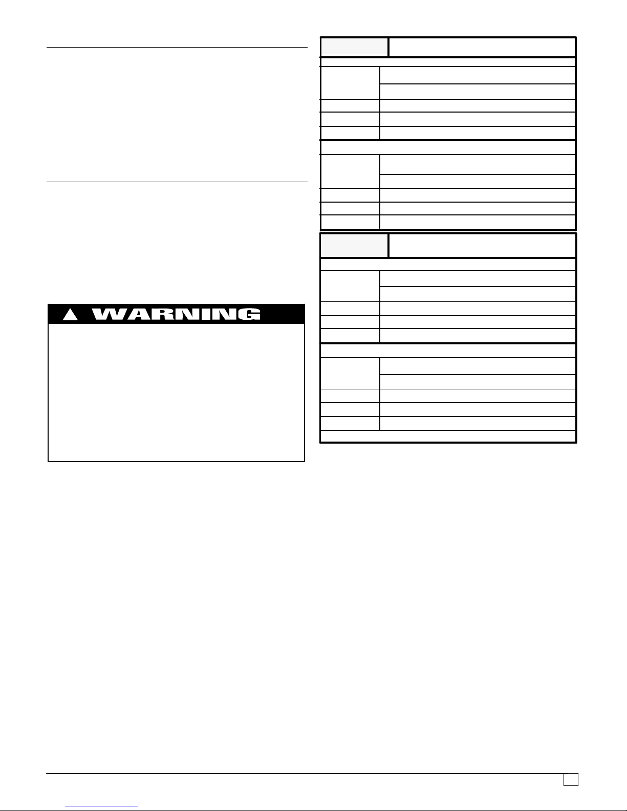
GAS PIPING
The gas supply line MUST be of adequate size to handle the
Btu/hr requirements and length of the run for the unit being
installed. Determine the minimum pipe size for natural gas
from the table in FIGURE 5 or FIGURE 6. Base the length
of the run from the gas meter or source to the unit.
Gas Pipe Size
Btu ratings of all other gas appliances MUST be considered
for sizing of main gas line. Check gas line to installation for
compliance with local codes or, in the absence of local
codes, with the National Fuel Gas Code NFPA
54−2005/ANSI Z223.1−2005 or in Canada the National
Standard CAN/CGA B149−1 or current editions.
Gas Pipe Size, Length and Btu/hr Capacity
for Schedule 40 Iron Pipe (English)
20′ 190 350 730 1,100 2,100
40′ 130 245 500 760 1,450
60′ 105 195 400 610 1,150
FIGURE 5
Btu/hr (in thousands)
LP GAS
NATURAL GAS
Pipe Length
(Includes
Fittings)
3
/4″ 1″ 11/4″ 11/2″ 2″
20′ 189 393 732 1,496 2,299
40′ 129 267 504 1,039 1,559
60′ 103 217 409 834 1,275
Btu/hr (in thousands)
Pipe Length
(Includes
Fittings)
1
/2″
3
/4″ 1″ 11/4″ 11/2″
Pipe Length
(Includes
Fittings)
6.1m 56 103 214 322 615
12.2m 38 72 147 223 425
18.3m 31 57 117 179 337
FIGURE 6
kW**
LP GAS
NATURAL GAS
Pipe Length
(Includes
Fittings)
3
/4″ 1″ 11/4″ 11/2″ 2″
6.1m 55 115 215 438 674
12.2m 38 78 148 305 457
18.3m 30 64 120 244 374
kW**
1
/2″
3
/4″ 1″ 11/4″ 11/2″
**kW (Kilowatts) is the metric equivalent of Btu/hr.
Gas Pipe Size, Length and Btu/hr Capacity
for Schedule 40 Iron Pipe (English)
PIPING AT UNIT
Connections
In the state of Massachusetts:
− This product must be installed by a licensed Plumber or
Gas Fitter.
− When flexible connections are used, the maximum
length shall not exceed 36 inches.
− When lever type gas shutoffs are used they shall be
T−handle type.
− The use of copper tubing for gas piping is not approved
by the state of Massachusetts.
NOTE: The rules listed apply to natural and LP gas pipe
installations.
1. If installation is for LP gas, have LP gas installer use
TWO−STAGE REGULATION and make all
connections from storage tank to unit.
2. Use black iron or steel pipe and fittings or other pipe
approved by local code.
3. If copper tubing is used, it MUST comply with limitation
set in Fuel Gas Code.
NOTE: If a flexible gas connector is used, it MUST be
acceptable to local authority. Connector MUST NOT be
used inside the furnace or be secured or supported by the
furnace or ductwork. Do not use a connector which has
 Loading...