

International comfort products PGF3 Series Installation Instructions Manual
Printed in U.S.A.
462 01 1101 01 07−29−09
PACKAGED GAS / ELECTRIC UNITS
Installation Instructions
PGF3 Series
Code: PGF3
International Comfort Products, LLC
Lewisburg, TN. 37091
TABLE OF CONTENTS
UNIT DIMENSIONS 2. . . . . . . . . . . . . . . . . . . . . . . . . . . . . . . . . . . . . . . . .
SAFE INSTALLATION REQUIREMENTS 3. . . . . . . . . . . . . . . . . . . . . . . . .
LOCATING THE UNIT 4. . . . . . . . . . . . . . . . . . . . . . . . . . . . . . . . . . . . . . .
CLEARANCES 4. . . . . . . . . . . . . . . . . . . . . . . . . . . . . . . . . . . . . . . . . . . .
INSTALLATION 4. . . . . . . . . . . . . . . . . . . . . . . . . . . . . . . . . . . . . . . . . . . .
GROUND LEVEL INSTALLATION 4. . . . . . . . . . . . . . . . . . . . . . . . . . . . . .
HOISTING 5. . . . . . . . . . . . . . . . . . . . . . . . . . . . . . . . . . . . . . . . . . . . . . . .
DOWNFLOW CONVERSION 5. . . . . . . . . . . . . . . . . . . . . . . . . . . . . . . . . .
HEATING VENT ASSEMBLY 5. . . . . . . . . . . . . . . . . . . . . . . . . . . . . . . . . .
CONDENSATE DRAIN 5. . . . . . . . . . . . . . . . . . . . . . . . . . . . . . . . . . . . . . .
COMBUSTION BLOWER PIPE INSTALLATION 5. . . . . . . . . . . . . . . . . . . .
PRE-EXISTING COMMON VENT CHECK 5. . . . . . . . . . . . . . . . . . . . . . . . .
GAS SUPPLY AND PIPING 6. . . . . . . . . . . . . . . . . . . . . . . . . . . . . . . . . . .
ORIFICES 7. . . . . . . . . . . . . . . . . . . . . . . . . . . . . . . . . . . . . . . . . . . .
ELECTRICAL WIRING 8. . . . . . . . . . . . . . . . . . . . . . . . . . . . . . . . . . .
DUCTWORK 10. . . . . . . . . . . . . . . . . . . . . . . . . . . . . . . . . . . . . . . . .
FILTERS 10. . . . . . . . . . . . . . . . . . . . . . . . . . . . . . . . . . . . . . . . . . . .
AIRFLOW ADJUSTMENT 11. . . . . . . . . . . . . . . . . . . . . . . . . . . . . . .
START-UP PROCEDURES 12. . . . . . . . . . . . . . . . . . . . . . . . . . . . . .
GAS PRESSURES 12. . . . . . . . . . . . . . . . . . . . . . . . . . . . . . . . . . . . .
HEATING START-UP PROCEDURES 13. . . . . . . . . . . . . . . . . . . . . .
OPERATION 14. . . . . . . . . . . . . . . . . . . . . . . . . . . . . . . . . . . . . . . . .
MAINTENANCE 14. . . . . . . . . . . . . . . . . . . . . . . . . . . . . . . . . . . . . . .
INSPECTION AND CLEANING 16. . . . . . . . . . . . . . . . . . . . . . . . . . . .
RIGGING 19. . . . . . . . . . . . . . . . . . . . . . . . . . . . . . . . . . . . . . . . . . .
WIRING DIAGRAMS 20 - 21. . . . . . . . . . . . . . . . . . . . . . . . . . . . . . . .
LOW
VOLTAGE
1/2`` CONDUIT
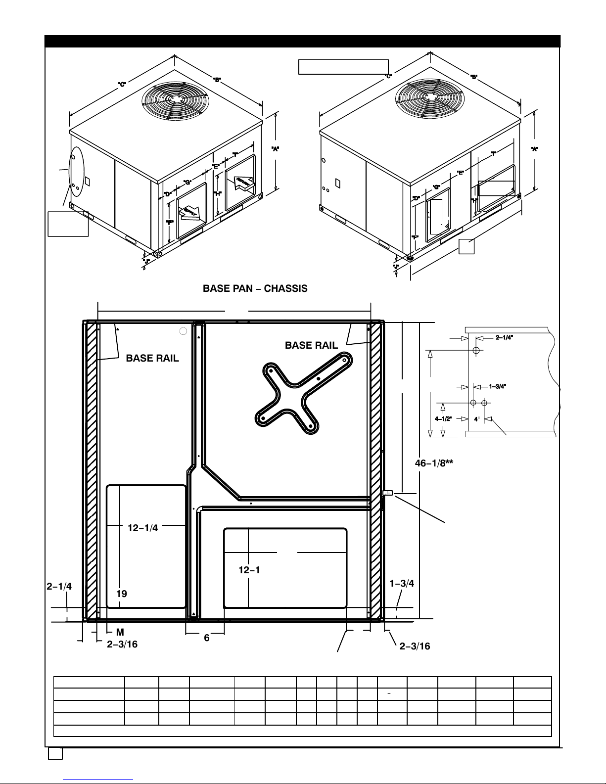
1. UNIT DIMENSIONS
ALL DIMENSIONS IN INCHES
GAS
CONNECTION
1/2`` PIPE
ELECTRICAL
POWER
CONDUIT
2 TON
2−1/2 TO 5 TON
K
See
Detail
Connections Detail
K
RETURN
SUPPLY
RETURN
SUPPLY
BASE PAN − CHASSIS
BASE RAIL
BASE RAIL
1−3/4
2−3/16
6
M
2−3/16
2−1/4
46−1/8**
12−1/4
19
12−1/4
19
L**
3−3/4
N
27
Condensate Drain
2
UNIT SIZE A B C D E F G H I J K L M N
2 Ton 29-1/2 47-1/2 47-1/2 3 9-1/2 12 14 12 14 4-1/2 16 42-3/4 1-9/16 46-1/2
2-1/2 TO 3-1/2 Ton 37-1/2 47-1/2 47-1/2 3-1/2 6-1/2 19 12 12 19 4-1/2 21-1/2 42-3/4 1-9/16 46-1/2
4 TO 5 Ton * 37-1/2 47-1/2 51 7-1/2 6-1/2 19 12 12 19 4-1/2 21-1/2 46-1/4 5-3/16 49-3/4
** Measured from inside to inside on base rails.
3
2. SAFE INSTALLATION REQUIREMENTS
Installation and servicing of air−conditioning equipment can
be hazardous due to system pressure and electrical
components. Only trained and qualified personnel should
install, repair, or service air−conditioning equipment.
Untrained personnel can perform basic maintenance
functions of cleaning coils and filters. All other operations
should be performed by trained service personnel. When
working on air−conditioning equipment, observe
precautions in the literature, tags, and labels attached to the
unit, and other safety precautions that may apply.
Follow all safety codes. Wear safety glasses and work
gloves. Use quenching cloth for unbrazing operations.
Have fire extinguisher available for all brazing operations.
FIRE, EXPLOSION, ELECTRICAL SHOCK, AND
CARBON MONOXIDE POISON HAZARD
Improper installation, adjustment, alteration, service,
maintenance, or use can cause carbon monoxide
poisoning, fire, or an explosion which can result in
personal injury or unit damage. Consult a qualified
installer, service agency, or gas supplier for information
or assistance. The qualified installer or agency must use
only factory−authorized kits or accessories when
modifying this product.
!
FIRE, EXPLOSION, ELECTRICAL SHOCK, AND
CARBON MONOXIDE POISON HAZARD
Failure to follow this warning could result in personal
injury, death and/or property damage.
Before performing service or maintenance operations
on unit, turn off gas supply to unit. Then turn off unit main
power switch and install lockout tag. Electrical shock or
explosion could cause serious injury or death.
!
Recognize safety information. This is the safety−alert
symbol . When you see this symbol in instructions or
manuals, be alert to the potential for personal injury.
Understand the signal words DANGER, WARNING,
CAUTION, and NOTE. These words are used with the
safety−alert symbol. DANGER identifies the most serious
hazards which will result in serious injury or death.
WARNING signifies a hazard which could result in serious
injury or death. CAUTION is used to identify unsafe
practices which may result in minor personal injury or
product and property damage. NOTE is used to highlight
suggestions which will result in enhanced installation,
reliability, or operation.
These instructions cover minimum requirements and
conform to existing national standards and safety codes. In
some instances, these instructions exceed certain local
codes and ordinances, especially those that may not have
kept up with changing residential construction practices.
We require these instructions as a minimum for a safe
installation.
FIRE, EXPLOSION, ELECTRICAL SHOCK, AND CARBON
MONOXIDE POISON HAZARD
!
Failure to carefully read and follow all instructions in this
manual could result in furnace malfunction, property
damage, personal injury and/or death.
Installation or repairs made by unqualified persons can
result in hazards to you and others. Installation MUST
conform with local building codes or, in the absence of
local codes, with the National Fuel Gas Code NFPA
54−2005/ANSI Z223.1−2005 and the National Electrical
Code NFPA70−2005 or in Canada the National Standard
CAN/CGA B149−1 and CSA C.22.1 − Canadian Electrical
Code Part 1.
The information contained in this manual is intended for
use by a qualified service technician familiar with safety
procedures and equipped with the proper tools and test
instruments.
SAFETY CONSIDERATIONS
• Use only with type of gas approved for this unit. Refer to
unit rating plate.
• Install this unit only in a location and position as specified
in section 3 of this manual.
• Never test for gas leaks with an open flame. Use a commercially available soap solution made specifically for the
detection of leaks to check all connections, as specified in
section 5.
• Always install unit to operate within the unit’s intended
temperature−rise range with a duct system, which has an
external static pressure within the allowable range, as
specified in section 9. Refer to unit rating plate for the allowable external static pressures.
• All connecting ductwork to the unit (supply and return)
must be sealed to the unit casing as specified in section 7.
• Do NOT use this furnace as a construction heater.
• Check to see that filters are installed correctly and are the
proper type an size.
NOTE: It is the personal responsibility and obligation of the
customer to contact a qualified installer to ensure that the
installation is adequate and conforms to governing codes
and ordinances.
UNIT SAFETY
CAUTION
!
Failure to follow this caution may reduce unit reliability.
It is recommended that a qualified service technician
check the heat exchanger integrity every two (2) years,
after the first four (4) years of operation.
INTRODUCTION
The PGF3 unit is a fully self−contained, combination
Category I gas heating/electric cooling unit designed for
outdoor installation (See pages 2 for unit dimensions). All
unit sizes have return and discharge openings for both
horizontal and downflow configurations, and are
factory−shipped with all downflow duct openings covered.
Units may be installed either on a rooftop, cement slab, or
directly on the ground if local codes permit.
Models with a ”1” in the twelfth position of the model number
are dedicated Low NOx units designed for California
installations. The emissions of these models do not exceed
40 nanograms of nitrogen oxide emissions per joule of heat
output as shipped from the factory, and must be installed in
California Air Quality Management Districts or any other
regions in North America where a Low NOx rule exists.
!
4
3. LOCATING THE UNIT
ACCESS PANELS
See FIGURE 1 for a general view of unit and location of
access panels.
CARBON MONOXIDE POISONING HAZARD.
!
Failure to follow this warning could result in personal
injury and/or death.
Keep blower door closed.
CLEARANCES
The location MUST allow for minimum clearances and
should not be adjacent to a patio or other area where the
unit’s operating sound level might be objectionable. The
combustion air inlet openings MUST not be obstructed (see
FIGURE 1). In addition, local codes MUST be observed.
NOTE: Units with available filter racks need a 26″ minimum
clearance at side of unit for removal of filters. See chart
below if unit is going to be placed near combustible
construction or materials.
While minimum clearances are acceptable for safety
reasons, they may not allow adequate air circulation around
the unit for proper operation in the cooling mode. Whenever
possible, it is desirable to allow additional clearance,
especially around the condenser inlet and discharge
openings.
Do NOT install the unit in a location that will permit
discharged air from the condenser to recirculate to the
condenser inlet.
Do NOT operate unit in a corrosive atmosphere
containing chlorine, fluorine, or any other corrosive
chemicals.
CAUTION
!
UNIT DAMAGE HAZARD
Failure to follow this caution may result in shorten life
of unit components.
Minimum Clearances to Combustible Construction
Furnace Plenum 2″ . . . . . . . . . . . . . . . . . . . . . . . . . . . . . . . . . . . . .
Duct Side 2″. . . . . . . . . . . . . . . . . . . . . . . . . . . . . . . . . . . . . . . . . . .
Condenser Inlet 30″ . . . . . . . . . . . . . . . . . . . . . . . . . . . . . . . . . . .
Blower Service (Side) 30″ . . . . . . . . . . . . . . . . . . . . . . . . . . . . . .
Control Service Side
(Front Combustion Air Inlet) 30″ . . . . . . . . . . . . .
Clearance between 3 Ft. Overhang
and Top of Unit 30″ . . . . . . . . . . . . . . . . . . . . . . . .
Combustible Base
(Wood or Class A, B or C
roof covering material) 0″. . . . . . . . . . . . . . . . . . . .
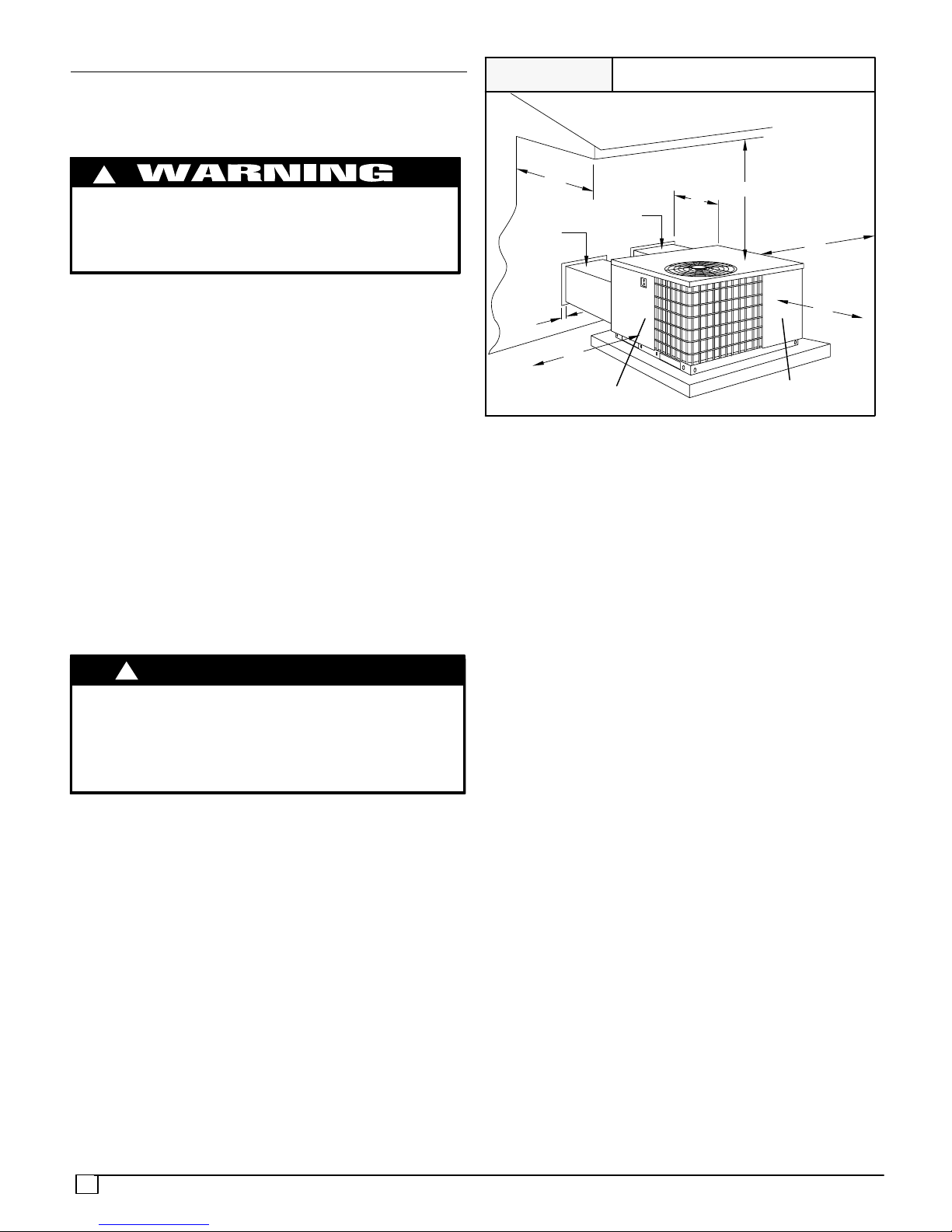
FIGURE 1
Minimum Clearances
30”
36”
Return
Air Duct
Supply
Air Duct
2”
30”
30”
30”
2”
Internal Filter
Access Panel (Filter Field Supplied)
Burner Compartment
Panel
INSTALLATION
NOTICE
Unit will NOT operate properly unless it is installed level front to rear and side to side. The slope MUST NOT be
greater than
1
/8″ per foot (10mm per meter). For side to
side leveling, the drain side MUST always be lower.
Ground Level Installation
Ground level platform requirements:
− The unit MUST be situated to provide safe access for
servicing.
− Platform may be made of either concrete or pressure
treated wood and MUST be level and strong enough to
support unit weight.
− Position platform separate from building foundation.
− Install in well−drained area, with top surface of platform
above grade level.
− Platform must be high enough to allow for proper
condensate trap installation and drainage. See
FIGURE 4 and associated text for more information
about condensate drainage.
Rooftop Installation
Rooftop platform requirements:
− The unit MUST be situated to provide safe access for
servicing.
− The existing roof structure MUST be adequate to
support the weight of the unit or the roof MUST be
reinforced.
Check the weight of the unit in relation to the roof
structure and local building codes or ordinances and
reinforce roof structure if necessary. See the last page
of this manual for unit weights.
− Support for the unit MUST be level and strong enough
to carry unit weight. The support may consist of a
platform or a combination of platform and roof beams or
curb.
− See Hoisting section for hoisting instructions.
5
HOISTING
NOTE: All access panels MUST be secured in place before
hoisting.
The unit should be hoisted with two lifting slings. Attach the
slings to rigging shackles that have been hooked through
holes in the base rail.
Two spreader bars MUST be placed on top of the unit to
protect the unit from damage from the pressure exerted by
the slings. Make sure that all equipment is adequate to
handle the weight of the unit and that the slings will not allow
the unit to shift.
Refer to FIGURE 19 on the back cover of this manual for
illustrated rigging instructions and weight chart.
DOWNFLOW CONVERSION
NOTE: In downflow applications with roof curbs or jack
stands, the center rail under the unit must be removed. The
center rail is attached to the base rail with screws.
These units are adaptable to downflow use. To convert to
downflow use, follow these steps:
1. Remove the blockoff plates found in the return air
compartment and the supply air compartment.
NOTE: Blockoff plate in the supply air compartment only
contains one screw. If reinstalling plate, back part of plate
MUST fit into mating dimples on flange. To reinstall, slant
plate into dimples, then put plate into position and fasten
with screw.
2. Install the removed plates on the horizontal return and
supply air openings.
3. Install roof curb on the building. Be sure to follow all
directions included with curb and all applicable building
codes in your installation.
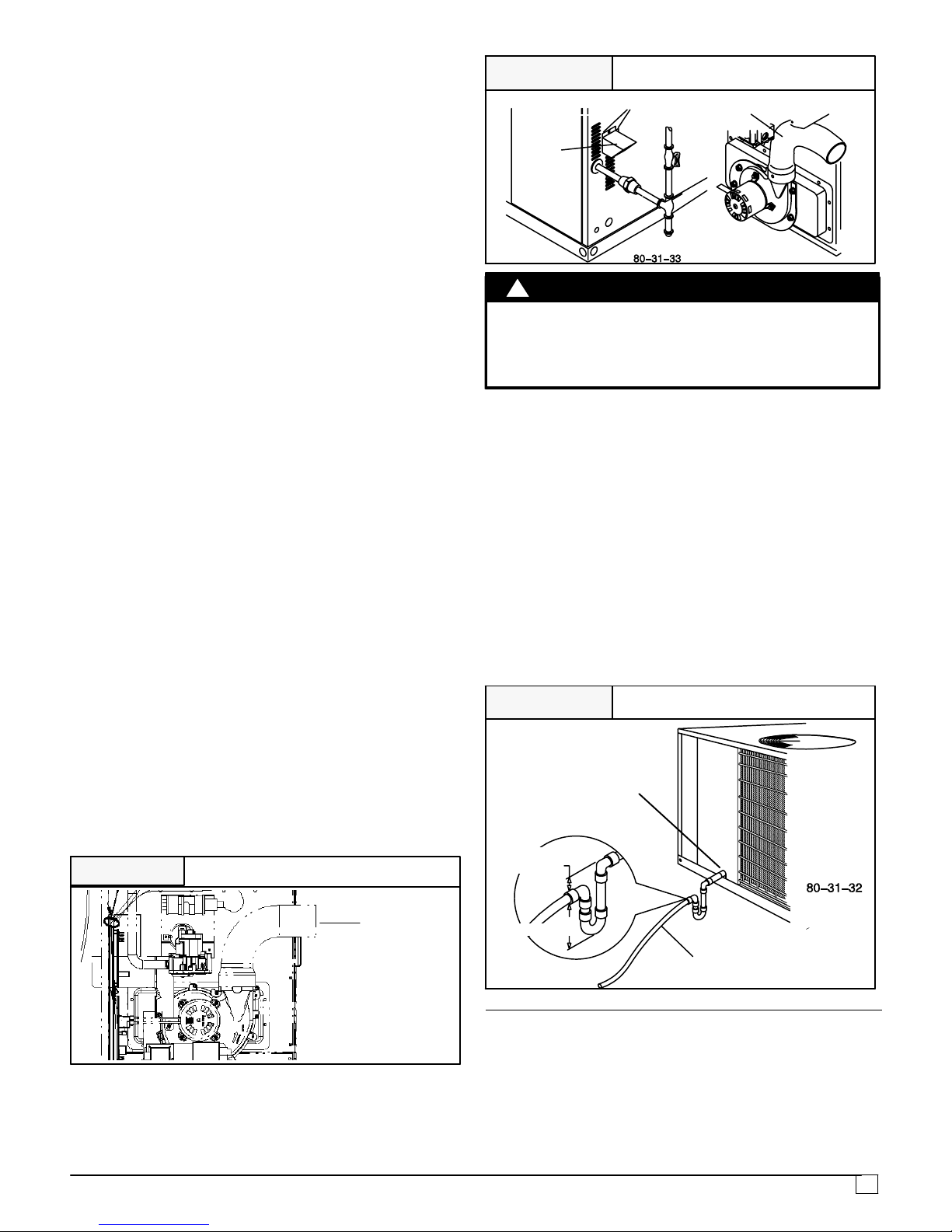
Combustion Blower Pipe Installation
Remove the combustion blower pipe from the right corner of
the burner compartment and position the end of the pipe
with the screw hole over the opening of the combustion
blower. The other end of the pipe should now be aligned
through the opening in the side panel of the unit. The pipe
should slightly protrude through the opening in the side
panel. See Figure 2.
Remove (1) chisel pointed #10 screw (self−drilling) taped to
the vent cap. Position the screw to the hole in the pipe and
drill through the combustion blower outlet securing the pipe
to the combustion blower.
FIGURE 2 Combustion Pipe Installation
Combustion
Pipe
Heating Vent Assembly
Refer to FIGURE 3 and assemble as shown.
FIGURE 3
Heating Vent Assembly
Flue PipeAttach with 2 screws
Heating
Vent
UNIT DAMAGE
CAUTION
!
Do not operate the unit without the vent assembly
installed.
Failure to follow this caution may result in unit
damage.
Condensate Drain
The condensate drain outlet is a
3
/4″ (19.1mm) female PVC
connection located at the bottom on the left hand side (see
FIGURE 4).
The circulating blower creates a negative pressure on the
condensate drain line that can prevent the condensate from
draining properly. To combat this negative pressure, a field
supplied condensate trap that will allow a standing column
of water of at least 2″ (50.8mm) MUST be installed . Top of
outlet from trap MUST be at least 1″ (25.4mm) below top of
outlet from unit. Install the trap as near to the unit as
possible for proper drainage.
A
3
/4″ (19.1mm) drain line MUST be installed if required by
local codes or if location of unit requires it. Run the drain line
to an open drain or other suitable disposal point.
FIGURE 4
Condensate Drain Information*
* Condensate trap MUST be installed.
3
/4″ (19.1mm)
Drain Line
1″
(25.4mm)
2″ (50.8mm)
3
/4″ (19.1mm)
Female PVC
Fitting
4. PRE−EXISTING COMMON VENT CHECK
If the installation of this new combination gas heat/electric
cool unit involves removing an existing gas−fired furnace
from a common vent system with other gas−fired
appliances (gas−fired hot water heater, etc.), the existing
vent system must be checked and inspected by a qualified
technician. The qualified technician can determine if the
existing vent system will properly vent the flue products of
the remaining gas−fired appliances. In many cases, the
6
existing vent system may be oversized for the remaining
appliances.
5. GAS SUPPLY AND PIPING
NOTE: Because there are many types of liquified petroleum
(LP) gases, the term LP as used in this manual refers to
propane gas. If you intend to use any type of LP gas, proper
precautions MUST be used in the handling, piping, and use
of such gas. NOTE: In Canada, installations MUST be
performed by licensed LP installers.
The UL rating plate located on the side panel on the unit
contains the model number, type of gas, gas input rating,
and other important information.
FIRE OR EXPLOSION HAZARD
Failure to follow this warning could result in personal
injury, death and/or property damage.
Make certain the unit is equipped to operate on the type of
gas available. Models designated as natural gas are to be
used with natural gas only. Models designated for use
with liquefied petroleum (LP) gas are shipped with
orifices sized for commercially pure propane gas. They
MUST not be used with butane or a mixture of butane and
propane unless properly sized orifices are installed by a
licensed LP installer.
!
GAS PIPING
The gas supply line MUST be of adequate size to handle the
Btu/hr requirements and length of the run for the unit being
installed. Determine the minimum pipe size for natural gas
from the table in FIGURE 5 or FIGURE 6. Base the length
of the run from the gas meter or source to the unit.
Gas Pipe Size
Btu ratings of all other gas appliances MUST be considered
for sizing of main gas line. Check gas line to installation for
compliance with local codes or, in the absence of local
codes, with the National Fuel Gas Code NFPA
54−2005/ANSI Z223.1−2005 or in Canada the National
Standard CAN/CGA B149−1 or current editions.
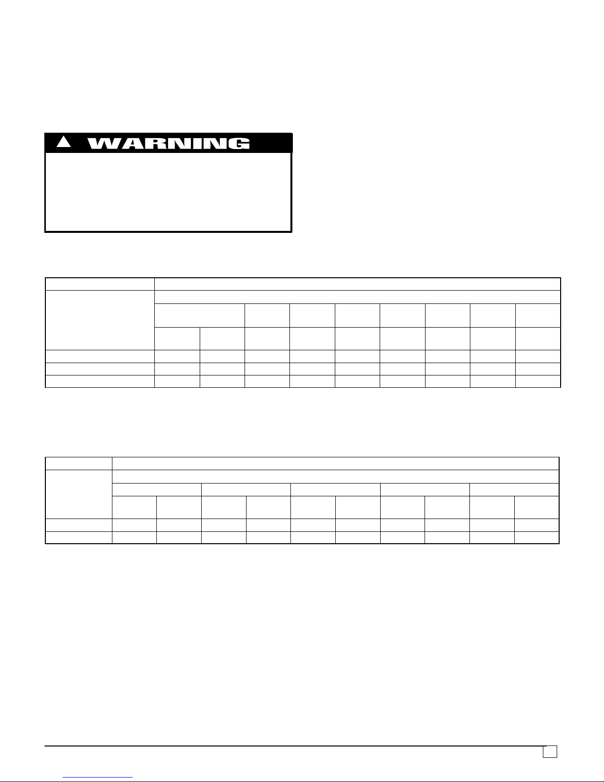
Gas Pipe Size, Length and Btu/hr Capacity
for Schedule 40 Iron Pipe (English)
20′ 190 350 730 1,100 2,100
40′ 130 245 500 760 1,450
60′ 105 195 400 610 1,150
FIGURE 5
Btu/hr (in thousands)
LP GAS
NATURAL GAS
Pipe Length
(Includes
Fittings)
3
/4″ 1″ 11/4″ 11/2″ 2″
20′ 189 393 732 1,496 2,299
40′ 129 267 504 1,039 1,559
60′ 103 217 409 834 1,275
Btu/hr (in thousands)
Pipe Length
(Includes
Fittings)
1
/2″
3
/4″ 1″ 11/4″ 11/2″
Pipe Length
(Includes
Fittings)
6.1m 56 103 214 322 615
12.2m 38 72 147 223 425
18.3m 31 57 117 179 337
FIGURE 6
kW**
LP GAS
NATURAL GAS
Pipe Length
(Includes
Fittings)
3
/4″ 1″ 11/4″ 11/2″ 2″
6.1m 55 115 215 438 674
12.2m 38 78 148 305 457
18.3m 30 64 120 244 374
kW**
1
/2″
3
/4″ 1″ 11/4″ 11/2″
**kW (Kilowatts) is the metric equivalent of Btu/hr.
Gas Pipe Size, Length and Btu/hr Capacity
for Schedule 40 Iron Pipe (English)
PIPING AT UNIT
Connections
NOTE: The rules listed apply to natural and LP gas pipe
installations.
1. If installation is for LP gas, have LP gas installer use
TWO−STAGE REGULATION and make all
connections from storage tank to unit.
2. Use black iron or steel pipe and fittings or other pipe
approved by local code.
3. If copper tubing is used, it MUST comply with limitation
set in Fuel Gas Code.
NOTE: If a flexible gas connector is used, it MUST be
acceptable to local authority. Connector MUST NOT be
used inside the furnace or be secured or supported by the
furnace or ductwork. Do not use a connector which has
previously serviced another gas appliance. Always use a
new listed connector.
FIRE OR EXPLOSION HAZARD
!
Failure to do so could result in personal injury, death
and/or property damage.
Gas connector MUST be properly installed and can NOT
be used inside the furnace.
4. Use pipe joint compound on external (male) threads
ONLY. Joint compound MUST be resistant to any
chemical action of LP gases. Do NOT put pipe
compound on last 2 threads of pipe.
5. Use ground joint unions and install a drip leg no less
than 3 inches (76 mm) long to trap dirt and moisture
before it can enter gas valve.
Overtightening assembly may cause damage to the gas
valve and/or wiring and may misalign the burners.
CAUTION
!
UNIT OPERATION AND COMPONENT DAMAGE HAZARD
Failure to follow this caution may result in misaligned
burners, flame rollout and or unit damage.
6. Use a wrench on gas valve when making connections
to prevent gas valve from turning. Do NOT use a pipe
wrench on the gas valve body.
7
7. Provide a 1/8 inch (3mm) National Pipe Thread (NPT)
plug for test gauge connection immediately upstream of
the gas supply connection to the furnace if none is
supplied with the gas valve of unit.
8. Install a manual shutoff valve and tighten all joints
securely.
LEAK CHECK /PRESSURE TESTING OF GAS SUPPLY
PIPING
FIRE OR EXPLOSION HAZARD
!
Failure to follow the safety warnings exactly could result in serious
injury, death or property damage.
Never test for gas leaks with an open flame. Use a commercially
available soap solution made specifically for the detection of leaks
to check all connections. A fire or explosion may result causing
property damage, personal injury or loss of life.
The unit and its equipment shutoff valve must be
disconnected from the gas supply piping system during any
pressure testing of that system at test pressures in excess
of .5 psi (3.5kPa).
The unit must be isolated from the gas supply piping system
by closing the equipment shut off valve during any pressure
testing of the gas supply piping system at test pressures
equal to or less than .5 psi (3.5 kPa).
ORIFICES
Orifice Sizes
Orifice sizes MUST be matched to the heating value of the
gas (see TABLE 1 & 2). Check with your gas supplier and
the National Fuel Gas Code ANSI Z223.1.
NOTE: An LP Conversion Kit MUST be used for conversion
to LP gas.
NOTE: For elevations above 2000 feet (610 meters), the
Btu input rating MUST be reduced by 4% for each 1000 feet
(305 meters) above sea level, unless the gas supplier’s
Btu/ft
3
content has already been adjusted for altitude.
Check Table 1 & 2 for the proper orifice sizes.
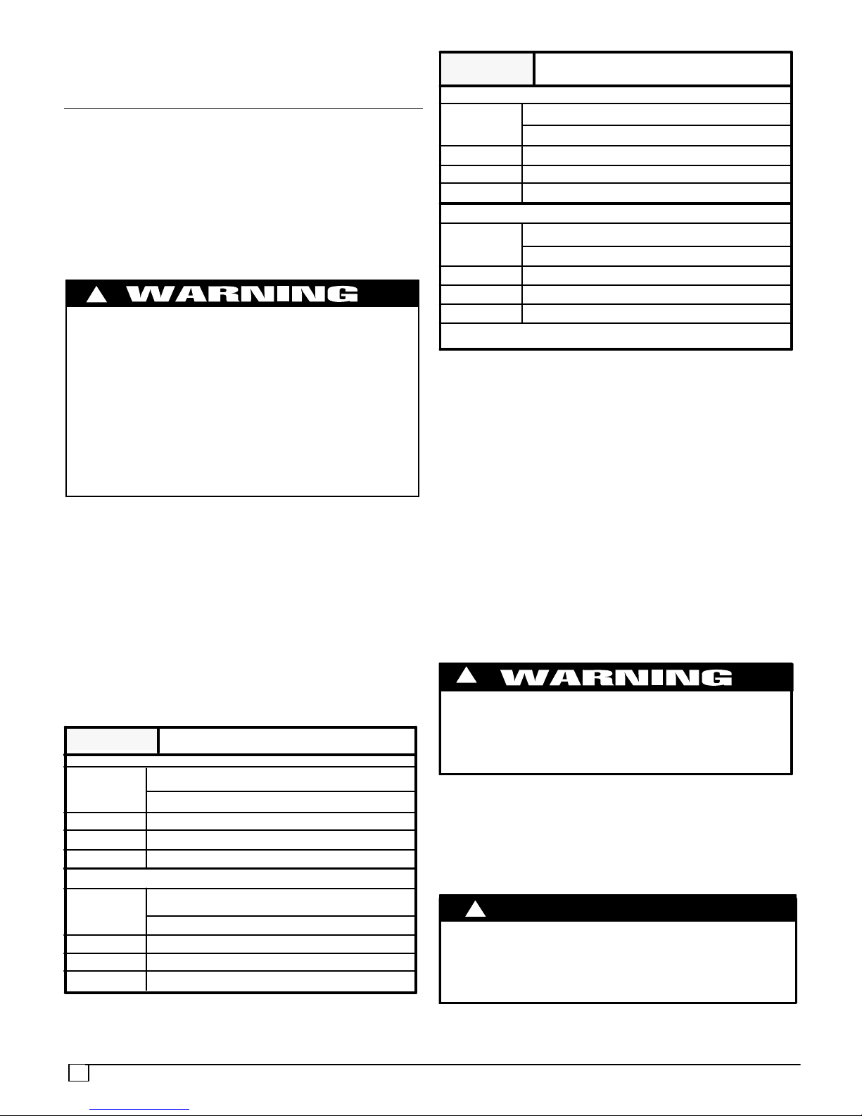
TABLE 1 & 2: Equivalent Orifice Sizes at High Altitudes
Table 1 NATURAL GAS ORIFICE SIZING
Nominal Heating Size
MEAN ELEVATION FEET ABOVE SEA LEVEL
0 to 2000 2001 to
4000
4001 to
5000
5001 to
6000
6001 to
7000
7001 to
8000
8001 to
9000
9001 to
10000
Orifice
Drill #
Kit
Number
Orifice
Drill #
Orifice
Drill #
Orifice
Drill #
Orifice
Drill #
Orifice
Drill #
Orifice
Drill #
Orifice
Drill #
040, 060, 080 44 1173863 45 46 47 47 48 48 49
100 41 1173865 43 43 43 44 44 45 46
120, 140 42 1173865 43 43 44 44 45 46 47
NOTE: The orifice sizes in the chart above derate the input rate at 4% per 1000 feet above sea level for altitudes exceeding 2000 feet
above sea level. If converting from LP gas to Natural Gas at altitudes exceeding 2000 feet above sea level, use part number
330732−401, plus the required orifice size # shown in Table 1. Natural Gas data is based on 0.60 specific gravity, a heating value of 1030
Btu/Cu.Ft., and 3.5” W.C. manifold pressure. For fuels with different specific gravity, consult the National Fuel Gas Code NFPA
54−2005/ANSI Z223.1−2005 or National Standard of Canada, Natural Gas and Propane Installation Code CSA B149.1−05.
Table 2
LP GAS ORIFICE SIZING
Nominal Heating
Size
MEAN ELEVATION FEET ABOVE SEA LEVEL
0 to 2000 2001 to 4000 4001 to 7000 7001 to 9000 9001 to 10,000
Orifice
Drill #
Kit
Number
Orifice
Drill #
Kit
Number
Orifice
Drill #
Kit
Number
Orifice
Drill #
Kit
Number
Orifice
Drill #
Kit
Number
040, 060, 080 55 1173857 55 1173857 56 1173859 56 1173859 57 1173861
100, 120, 140 54 1173855 55 1173857 55 1173857 56 1173859 56 1173859
NOTE: The orifice sizes in the chart above derate the input rate at 4% per 1000 feet above sea level for altitudes exceeding 2000 feet
above sea level. LP Gas data is based on 1.52 specific gravity, a heating value of 2500 Btu/Cu.Ft., and 10.0” W.C. manifold pressure. For
fuels with different specific gravity, consult the National Fuel Gas Code NFPA 54−2005/ANSI Z223.1−2005 or National Standard of
Canada, Natural Gas and Propane Installation Code CSA B149.1−05.
 Loading...