

International comfort products FHS Series, FHS072 AA2 Series, FAS Series, FAS240, FAS072 Installation Instructions Manual
...
INSTALLATION INSTRUCTIONS
FAS/FHS Series, Package Air Handling Units
6 to 30 Ton Air Conditioners
6 to 20 Ton Heat Pump
Installation, Start-Up, and Service Instructions
CONTENTS
SAFETY CONSIDERATIONS . . . . . . . . . . . . . . . . 1
PRE-INSTALLATION. . . . . . . . . . . . . . . . . . . . . . . 2
Moving and Storage. . . . . . . . . . . . . . . . . . . . . . . . 2
Rigging. . . . . . . . . . . . . . . . . . . . . . . . . . . . . . . . . . 2
INSTALLATION . . . . . . . . . . . . . . . . . . . . . . . . . . . 2
General . . . . . . . . . . . . . . . . . . . . . . . . . . . . . . . . . 2
Uncrating . . . . . . . . . . . . . . . . . . . . . . . . . . . . . . . . 2
Accessories . . . . . . . . . . . . . . . . . . . . . . . . . . . . . . 2
Rated Indoor Airflow (cfm) . . . . . . . . . . . . . . . . . . . 2
Unit Positioning . . . . . . . . . . . . . . . . . . . . . . . . . . 14
Unit Isolation . . . . . . . . . . . . . . . . . . . . . . . . . . . . 15
Refrigerant Piping Access . . . . . . . . . . . . . . . . . . 15
Refrigerant Piping . . . . . . . . . . . . . . . . . . . . . . . . 15
Condensate Drain . . . . . . . . . . . . . . . . . . . . . . . . 21
Fan Motors and Drives . . . . . . . . . . . . . . . . . . . . 21
Power Supply and Wiring . . . . . . . . . . . . . . . . . . 21
Connecting Ductwork. . . . . . . . . . . . . . . . . . . . . . 27
• DISCHARGE CONNECTIONS
• RETURN CONNECTIONS
• OUTDOOR-AIR INLET CONNECTIONS
Return-Air Filters . . . . . . . . . . . . . . . . . . . . . . . . . 27
START-UP. . . . . . . . . . . . . . . . . . . . . . . . . . . . . . 28
Adjusting TXV for Superheat . . . . . . . . . . . . . . . . 28
SERVICE . . . . . . . . . . . . . . . . . . . . . . . . . . . . . . . 29
Panels . . . . . . . . . . . . . . . . . . . . . . . . . . . . . . . . . 29
Fan Motor Lubrication . . . . . . . . . . . . . . . . . . . . . 29
Fan Shaft Bearings . . . . . . . . . . . . . . . . . . . . . . . 29
Centering Fan Wheel. . . . . . . . . . . . . . . . . . . . . . 29
Fan Shaft Position Adjustment . . . . . . . . . . . . . . 29
Individual Fan Wheel Adjustment . . . . . . . . . . . . 30
Fan Belts . . . . . . . . . . . . . . . . . . . . . . . . . . . . . . . 30
Fan Rotation . . . . . . . . . . . . . . . . . . . . . . . . . . . . 30
Fan Pulley Alignment. . . . . . . . . . . . . . . . . . . . . . 30
Pulley and Drive Adjustment . . . . . . . . . . . . . . . . 31
Condensate Drains . . . . . . . . . . . . . . . . . . . . . . . 31
Return-Air Filters . . . . . . . . . . . . . . . . . . . . . . . . . 31
Coil Removal . . . . . . . . . . . . . . . . . . . . . . . . . . . . 31
Cleaning Cooling Coil . . . . . . . . . . . . . . . . . . . . . 31
Cleaning Insulation . . . . . . . . . . . . . . . . . . . . . . . 31
Replacing Filters . . . . . . . . . . . . . . . . . . . . . . . . . 31
START-UP CHECKLIST . . . . . . . . . . . . . . . . . CL-1
SAFETY CONSIDERATIONS
Installation and servicing of air-conditioning equipment can
be hazardous due to system pressure and electrical
components. Only trained and qualified service personnel
should install, repair, or service air-conditioning equipment.
Untrained personnel can perform basic maintenance
functions of cleaning coils and filters and replacing filters. All
other operations should be performed by trained service
personnel. When working on air-conditioning equipment,
observe precautions in the literature, tags and labels
attached to the unit, and other safety precautions that may
apply.
Follow all safety codes, including ANSI (American National
Standards Institute) Z223.1. Wear safety glasses and work
gloves. Use quenching cloth for unbrazing operations. Have
fire extinguisher available for all brazing operations.
It is important to recognize safety information. This is the
safety-alert symbol . When you see this symbol on the
unit and in instructions or manuals, be alert to the potential
for personal injury.
Understand the signal words DANGER, WARNING,
CAUTION, and NOTE. These words are used with the
safety-alert symbol. DANGER identifies the most serious
hazards which will result in severe personal injury or death.
WARNING signifies hazards which could result in personal
injury or death. CAUTION is used to identify unsafe
practices, which may result in minor personal injury or
product and property damage. NOTE is used to highlight
suggestions which will result in enhanced installation,
reliability, or operation.
WARNING
ELECTRICAL SHOCK HAZARD
Failure to follow this warning could cause personal injury
or death.
Before performing service or maintenance operations on
unit, turn off main power switch to unit and install lock(s)
and lockout tag(s). Ensure electrical service to rooftop
unit agrees with voltage and amperage listed on the unit
rating plate. Unit may have more than one power switch.
WARNING
UNIT OPERATION AND SAFETY HAZARD
Failure to follow this warning could cause personal inju-
ry, death and/or equipment damage.
R-410A refrigerant systems operate at higher pres-
sures than standard R-22 systems. Do not use R-22
service equipment or components on R-410A refrigerant equipment.
WARNING
PERSONAL INJURY AND ENVIRONMENTAL
HAZARD
Failure to follow this warning could cause personal injury
or death.
Relieve pressure and recover all refrigerant before system repair or final unit disposal.
Wear safety glasses and gloves when handling refrigerants. Keep torches and other ignition sources away from
refrigerants and oils.
508 01 1603 01 7-19
CAUTION
CUT HAZARD
Failure to follow this caution may result in personal
injury.
Sheet metal parts may have sharp edges or burrs. Use
care and wear appropriate protective clothing, safety
glasses and gloves when handling parts and servicing
air conditioning equipment.
CAUTION
UNIT OPERATION HAZARD
Failure to follow this caution could cause equipment
damage.
Ensure voltage listed on unit data plate agrees with elec-
trical supply provided for the unit.
PRE-INSTALLATION
1. The power supply (v, Ph, and Hz) must correspond to
that specified on unit rating plate.
2. The electrical supply provided by the utility must be
sufficient to handle load imposed by this unit.
3. Refer to the General Installation section and Fig. 1-3
for locations of electrical inlets, condensate drain,
duct connections, and required clearances before
setting unit in place.
4. This installation must conform with local building
codes and with the NEC (National Electrical Code) or
ANSI (American National Standards Institute)/NFPA
(National Fire Protection Association) latest revision.
Refer to provincial and local plumbing or wastewater
codes and other applicable local codes.
Moving and Storage
To transfer unit from truck to storage site, use a fork truck.
Do not stack units more than 2 high during storage. If unit is
to be stored for more than 2 weeks before installation,
choose a level, dry storage site free from vibration. Do not
remove plastic wrap or skid from unit until final installation.
CAUTION
UNIT DAMAGE HAZARD
Failure to follow this caution may result in equipment
damage.
All panels must be in place when rigging. Unit is not de-
signed for handling by fork truck when packaging is removed.
If using top crate as spreader bar, once unit is set, carefully lower wooden crate off building roof top to ground.
Ensure that no people or obstructions are below prior to
lowering the crate.
Rigging
All FAS/FHS units can be rigged by using the shipping skid.
Units are shipped fully assembled. Do not remove shipping
skids or protective covering until unit is ready for final placement; damage to bottom panels can result. Use slings and
spreader bars as applicable to lift unit.
INSTALLATION
General
Allow the following clearances for service access and
airflow:
• Rear: 3 ft (914 mm) [2
heat accessory]
•Front: 2
• Right side: 2
• Left side: 2
1
/2 ft (762 mm)
1
/2 ft (762 mm)
1
/2 ft (762 mm)
1
/2 ft (762 mm) with electric
For units equipped with an economizer, refer to the accessory installation instructions for additional clearance requirements. Be sure floor, wall, or ceiling can support unit weight
(Tables 4 – 11). See Fig. 1-3 for dimensions.
Uncrating
Move unit as near as possible to final location before removing shipping skid.
Remove metal banding, top skid, and plastic wrap. Examine
unit for shipping damage. If shipping damage is evident, file
claim with transportation agency. Remove base skid just prior to actual installation.
Check nameplate information against available power supply and model number description in Fig. 4.
NOTE: Be sure to remove the styrofoam shipping pad from
the thermostatic expansion valve (TXV). Verify that it has
been removed. See Fig. 5.
Accessories
Refer to instructions shipped with each accessory for specific information.
Rated Indoor Airflow (cfm)
Tables 1-3 list the rated indoor airflow used for the AHRI
efficiency rating for the units covered in this document.
There is no matched pair available for size 300 and 336
models.
Table 1 — CAS (Single Circuit) with FAS
MODEL NUMBER FULL LOAD AIRFLOW (CFM)
CAS072*A/B - FAS072 2400
CAS072*G/H - FAS072 2625
CAS090*G/H - FAS091 3000
CAS091 - FAS091 3000
CAS121 - FAS120 4000
CAS151 - FAS150 4375
CAS181 - FAS180 6000
CAS241 - FAS240 8300
Table 2 — (Dual Circuit) with FAS
MODEL NUMBER FULL LOAD AIRFLOW (CFM)
CAS120 - FAS120 4000
CAS150 - FAS150 4400
CAS180 - FAS180 6000
CAS240 - FAS240 8300
Table 3 — CHS with FHS
MODEL NUMBER FULL LOAD AIRFLOW (CFM)
CHS072*A/B - FHS072 2400
CHS072*G/H - FHS072 2400
CHS091*A/B - FHS091 3000
CHS091*G/H - FHS091 2625
CHS121*A/B - FHS120 3000
CHS121*G/H - FHS120 3000
CHS180 - FHS180 6000
CHS240 - FHS240 7400
2 Specifications subject to change without notice. 508 01 1603 01
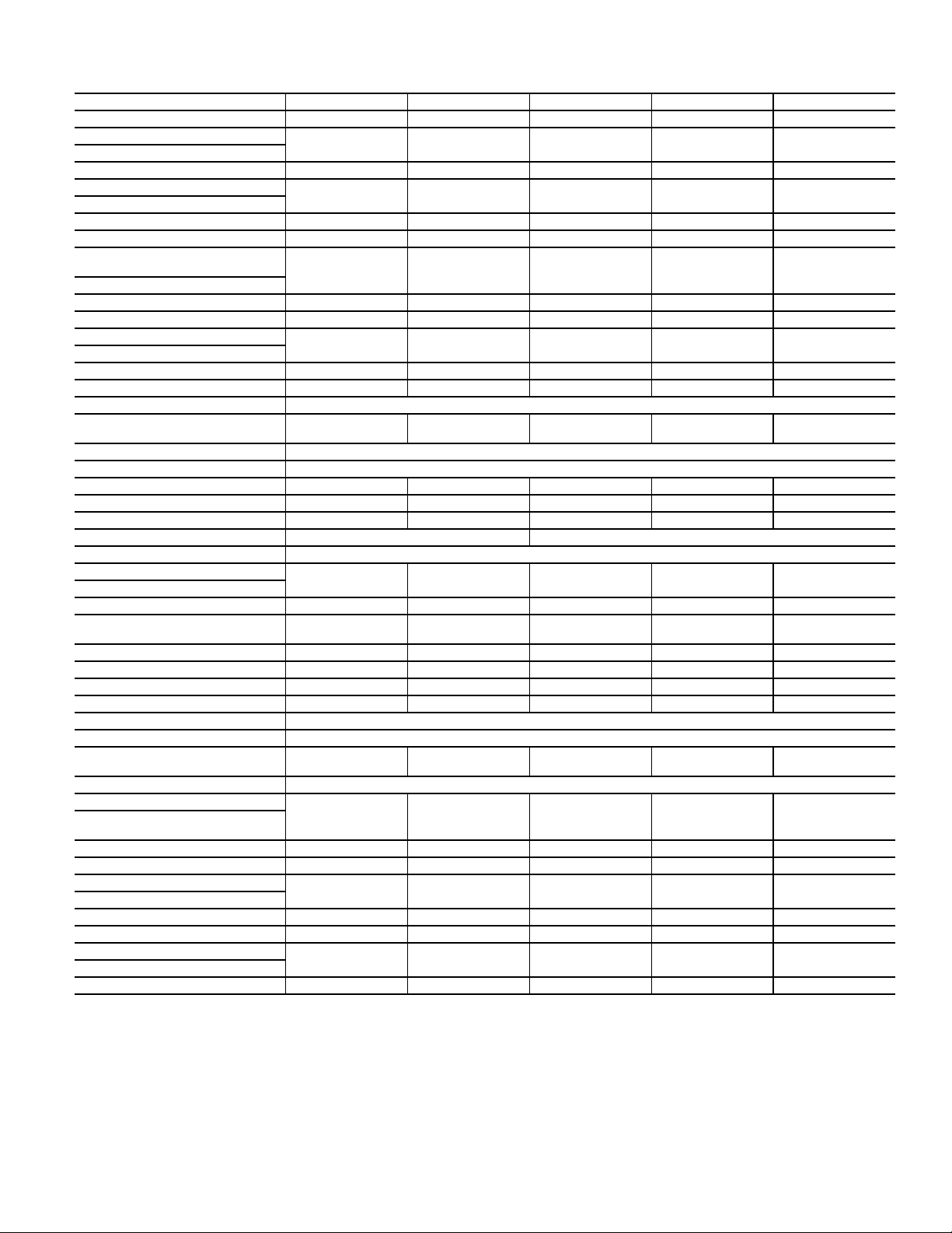
Table 4 — Physical Data (English) — 6 to 15 Ton Cooling Units (FAS)
FAS UNIT 072 091 120 150 180
NOMINAL CAPACITY (Tons) 6 7.5 10 12.5 15
OPERATING WEIGHT (lb)
Base Unit with TXV 399 404 425 695 713
Plenum 175 175 175 225 225
FANS
Qty...Diam. (in.) 1...15 1...15 1...15 2...15 2...15
Nominal Airflow (cfm) 2400 3000 4000 5000 6000
Airflow Range (cfm) 1800-3000 2250-3750 3000-5000 3750-6250 4500-7500
Nominal Motor Hp (Standard
Motor)
208/230-1-60 1.32.4———
208/230-3-60 and 460-3-60 2.4 2.4 2.4 2.9 3.7
575-3-60 1.0 2.0 2.0 3.0 3.0
Motor Speed (rpm)
208/230-1-60 1725 1725 — — —
208/230-3-60 and 460-3-60 1725 1725 1725 1725 1725
575-3-60 1725 1725 1725 1725 1725
REFRIGERANT R-410A
Operating charge (lb) (approx
per circuit)*
DIRECT-EXPANSION COIL Enhanced Copper Tubes, Aluminum Sine-Wave Fins
Max Working Pressure (psig) 650
Face Area (sq ft) 6.67 8.33 10.0 13.25 17.67
No. of Splits 11222
No. of Circuits per Split 12 15 9 12 16
Split Type...Percentage — Face...50/50
Rows...Fins/in. 4...15
PIPING CONNECTIONS
Quantity...Size (in.)
DX Coil — Suction (ODF) 1...1
DX Coil — Liquid
Refrigerant (ODF)
Steam Coil, In (MPT) 1...21/
Steam Coil, Out (MPT) 1...11/
Hot Water Coil, In (MPT) 1...11/
Hot Water Coil, Out (MPT) 1...1
Condensate (PVC) 1...1
FILTERS Throwaway — Factory Supplied
Quantity...Size (in.) 4...16 x 24 x 2 4...16 x 24 x 2 4...16 x 24 x 2
Access Location Either Side
STEAM COIL†
Max Working Pressure (psig
at 260°F)
Total Face Area (sq ft) 6.67 6.67 6.67 13.33 13.33
Rows...Fins/in. 1...9 1...9 1...9 1...10 1...10
HOT WATER COIL†
Max Working Pressure (psig) 150 150 150 150 150
Total Face Area (sq ft) 6.67 6.67 6.67 13.33 13.33
Rows...Fins/in. 2...8.5 2...8.5 2...8.5 2...8.5 2...8.5
Water Volume
(gal) 8.3 8.3 8.3 13.9 13.9
3
(ft
) 1.1 1.1 1.1 1.85 1.85
LEGEND
DX — Direct Expansion
TXV — Thermostatic Expansion Valve
* Units are shipped without refrigerant charge.
† Field-installed accessory only.
3.0 3.0 1.5/1.5 2.0/2.0 2.5/2.5
1
1...
/
8
5
/
8
2
2
2
1
/
2
1...11/
1...5/
1...21/
1...11/
1...11/
1...11/
8
8
2
2
2
2
2...11/
8
2...5/
8
1...21/
2
1...11/
2
1...11/
2
1...11/
5
2
/8 ODM / 11/4 IDF
2...11/
8
2...5/
8
1...21/
2
1...11/
2
1...2 1...2
1...2 1...2
4...16 x 20 x 2
4...16 x 24 x 2
2...11/
2...5/
1...21/
1...11/
4...16 x 20 x 2
4...16 x 24 x 2
20 20 20 20 20
8
8
2
2
508 01 1603 01 Specifications subject to change without notice. 3
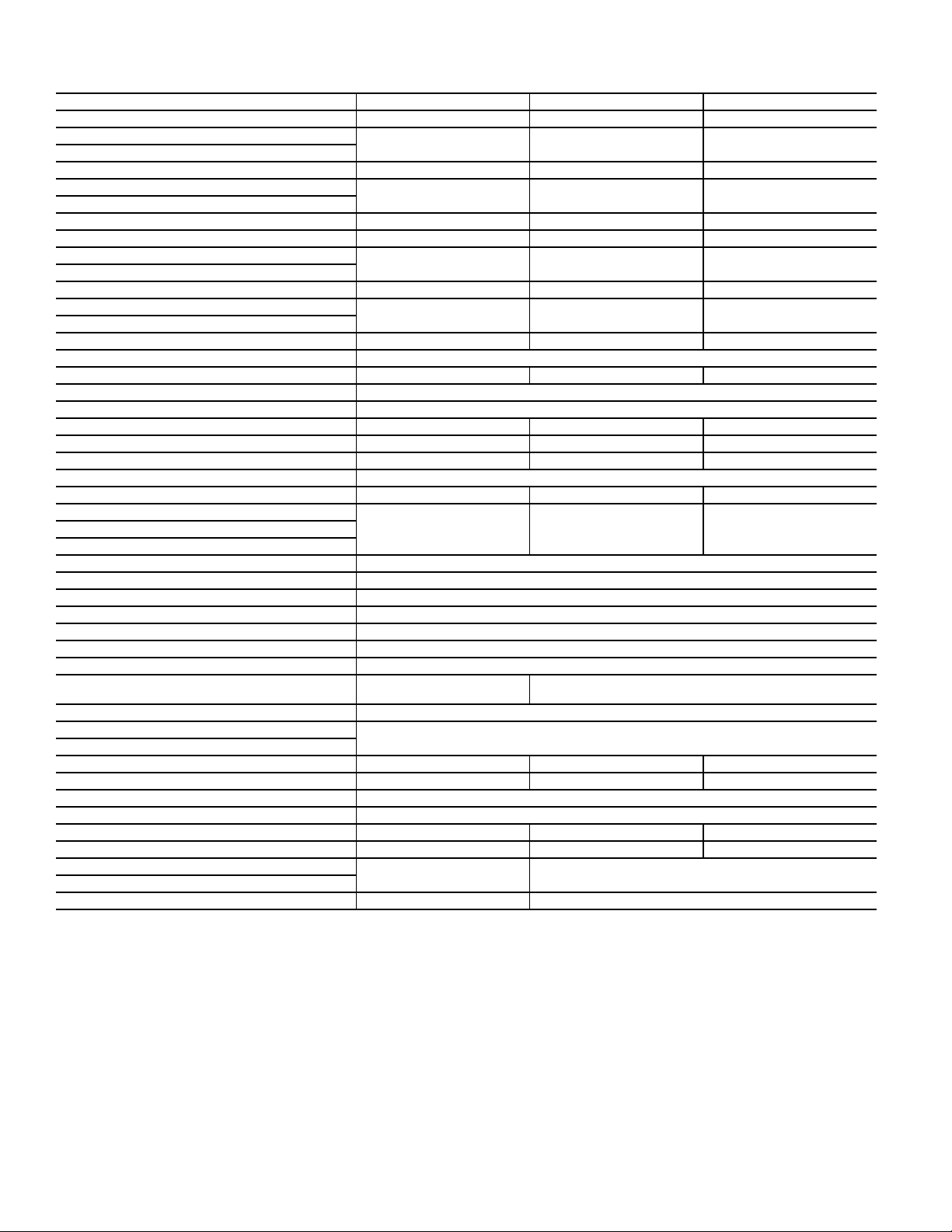
Table 5 — Physical Data (English) — 20 to 30 Ton Cooling Units (FAS)
FAS UNIT 240 300 336
NOMINAL CAPACITY (Tons) 20 25 30
OPERATING WEIGHT (lb)
Base Unit with TXV 730 1050 1062
Plenum 225 325 325
FANS
Qty...Diam. (in.) 2...15 2...18 2...18
Nominal Airflow (cfm) 8000 10000 12000
Airflow Range (cfm) 6000 – 10000 7500 – 12500 9000 – 15000
Nominal Motor Hp (Standard Motor)
208/230-3-60 and 460-3-60 5.0 7.5 10.0
575-3-60 5.0 7.5 10.0
Motor Speed (rpm)
208/230-3-60 and 460-3-60 1745 1745 1745
575-3-60 1745 1755 1755
REFRIGERANT R-410A
Operating charge (lb) (approx per circuit)* 3.5 4.5 5.0
DIRECT-EXPANSION COIL Enhanced Copper Tubes, Aluminum Sine-Wave Fins
Max Working Pressure (psig) 650
Face Area (sq ft) 19.88 24.86 29.83
No. of Splits 222
No. of Circuits per Split 18 20 24
Split Type...Percentage Face...50/50
Rows...Fins/in. 4...15 4...15 4...15
PIPING CONNECTIONS
Quantity...Size (in.)
DX Coil — Suction (ODF) 2...1
DX Coil — Liquid Refrigerant (ODF) 2...5/
Steam Coil, In (MPT) 1...21/
Steam Coil, Out (MPT) 1...1/
Hot Water Coil, In (MPT) 1...2
Hot Water Coil, Out (MPT) 1...2
Condensate (PVC) 1...1
FILTERS Throwaway — Factory Supplied
Quantity...Size (in.)
Access Location Either Side
STEAM COIL†
Max Working Pressure (psig at 260°F) 20
Total Face Area (sq ft) 13.33 15.0 15.0
Rows...Fins/in. 1...10 1...10 1...10
HOT WATER COIL†
Max Working Pressure (psig) 150
Total Face Area (sq ft) 13.33 15.0 15.0
Rows...Fins/in. 2...8.5 2...12.5 2...12.5
Water Volume
(gal) 13.9 14.3
3
(ft
) 1.86 1.90
LEGEND
DX — Direct Expansion
TXV — Thermostatic Expansion Valve
* Units are shipped without refrigerant charge.
† Field-installed accessory only.
1
/
8
4...16 x 20 x 2
4...16 x 24 x 2
2...13/
8
8
2
2
1
/4 ODM/1 IDF
4...20 x 24 x 2
4...20 x 25 x 2
2...13/
8
4 Specifications subject to change without notice. 508 01 1603 01
Table 6 — Physical Data (SI) — 21 to 52 kW Cooling Units (FAS)
FAS UNIT 072 091 120 150 180
NOMINAL CAPACITY (kW) 21 26 35 43 52
OPERATING WEIGHT (kg)
Base Unit with TXV 173 175 184 304 311
Plenum 80 80 80 102 102
FANS
Qty...Diam. (mm) 1...381 1...381 1...381 2...381 2...381
Nominal Airflow (L/s) 1133 1604 1888 2360 2831
Airflow Range (L/s) 850-1416 1203-2006 1416-2360 1770-2949 2124-3539
Nominal Motor kW (Standard
Motor)
208/230-1-60 0.97 1.79 — — —
208/230-3-60 and 460-3-60 1.79 1.79 1.79 2.16 2.16
575-3-60 0.75 1.49 1.49 2.24 2.24
Motor Speed (r/s)
208/230-1-60 28.8 28.8 — — —
208/230-3-60 and 460-3-60 28.8 28.8 28.8 28.8 28.8
575-3-60 28.8 28.8 28.8 28.8 28.8
REFRIGERANT R-410A
Operating charge (kg) (approx
per circuit)*
DIRECT-EXPANSION COIL Enhanced Copper Tubes, Aluminum Sine-Wave Fins
Max Working Pressure (kPag) 4481 4481 4481 4481 4481
Face Area (sq m) 0.62 0.77 0.93 0.93 1.64
No. of Splits 11222
No. of Circuits per Split 12 15 9 12 16
Split Type...Percentage — — Face...50/50
Rows...Fins/m 4...591 4...591 4...591 4...591 4...591
PIPING CONNECTIONS
Quantity...Size (in.)
DX Coil — Suction (ODF) 1...1
DX Coil — Liquid
Refrigerant (ODF)
Steam Coil, In (MPT) 1...21/
Steam Coil, Out (MPT) 1...11/
Hot Water Coil, In (MPT) 1...11/
Hot Water Coil, Out (MPT) 1...1
Condensate (PVC) 1...1
FILTERS Throwaway — Factory Supplied
Quantity...Size (mm) 4...406 x 610 x 51
Access Location Either Side
STEAM COIL†
Max Working Pressure (kPag
at 126°C)
Total Face Area (sq m) 0.62 0.62 0.62 1.24 1.24
Rows...Fins/m 1...355 1...355 1...355 1...394 1...394
HOT WATER COIL†
Max Working Pressure (kPag) 1034
Total Face Area (sq m) 0.62 0.62 0.62 1.24 1.24
Rows...Fins/m 2...335 2...335 2...335 2...335 2...335
Water Volume
(L) 31.4 31.4 31.4 52.6 52.6
3
(m
) 0.031 0.031 0.031 0.052 0.052
LEGEND
DX — Direct Expansion
TXV — Thermostatic Expansion Valve
* Units are shipped without refrigerant charge.
† Field-installed accessory only.
1.36 1.36 0.68/0.68 0.90/0.90 1.13/1.13
1
1...
/
8
5
/
8
2
2
2
1
/
2
1...11/
1...5/
1...21/
1...11/
1...11/
1...11/
8
8
2
2
2
2
2...11/
8
2...5/
8
1...21/
2
1...11/
2
1...11/
2
1...11/
5
2
/8 ODM / 11/4 IDF
2...11/
2...5/
1...21/
1...11/
8
8
2
2
2...11/
2...5/
1...21/
1...11/
1...2 1...2
1...2 1...2
4...406 x 508 x 51
4...406 x 610 x 51
138
8
8
2
2
508 01 1603 01 Specifications subject to change without notice. 5

Table 7 — Physical Data (SI) — 70 to 105 kW Cooling Units (FAS)
FAS UNIT 240 300 336
NOMINAL CAPACITY (kW) 70 87 105
OPERATING WEIGHT (kg)
Base Unit with TXV 331 477 482
Plenum 102 148 148
FANS
Qty...Diam. (mm) 2...381 2...457 2...457
Nominal Airflow (L/s) 3775 4119 5663
Airflow Range (L/s) 2831 – 4719 3539 – 5899 4247 – 7079
Nominal Motor kW (Standard Motor)
208/230-3-60 and 460-3-60 3.73 5.60 7.46
575-3-60 3.73 5.60 7.46
Motor Speed (r/s)
208/230-3-60 and 460-3-60 29.1 29.1 29.1
575-3-60 29.1 29.3 29.3
REFRIGERANT R-410A
Operating charge (kg) (approx per circuit)* 1.59 2.04 2.27
DIRECT-EXPANSION COIL Enhanced Copper Tubes, Aluminum Sine-Wave Fins
Max Working Pressure (kPag) 4481
Face Area (sq m) 1.85 2.30 2.77
No. of Splits 222
No. of Circuits per Split 18 20 24
Split Type...Percentage Face...50/50
Rows...Fins/m 4...591 4...591 4...591
PIPING CONNECTIONS
Quantity...Size (in.)
DX Coil — Suction (ODF) 2...1
DX Coil — Liquid Refrigerant (ODF) 2...5/
Steam Coil, In (MPT) 1...21/
Steam Coil, Out (MPT) 1...1/
Hot Water Coil, In (MPT) 1...2
Hot Water Coil, Out (MPT) 1...2
Condensate (PVC) 1...1
FILTERS Throwaway — Factory Supplied
Quantity...Size (mm)
4...406 x 508 x 51
4...406 x 610 x 51
Access Location Either Side
STEAM COIL†
Max Working Pressure (kPag at 126°C) 138
Total Face Area (sq m) 1.24 1.39 1.39
Rows...Fins/m 1...394 1...394 1...394
HOT WATER COIL†
Max Working Pressure (kPag) 1034
Total Face Area (sq m) 1.24 1.39 1.39
Rows...Fins/m 2...335 2...493 2...493
Water Volume
(L) 52.6 54.1
3
(m
) 0.052 0.054
LEGEND
DX — Direct Expansion
TXV — Thermostatic Expansion Valve
* Units are shipped without refrigerant charge.
† Field-installed accessory only.
1
/
8
2...13/
8
8
2
2
1
/4 ODM/1 IDF
2...13/
8
4...508 x 610 x 51
4...508 x 635 x 51
6 Specifications subject to change without notice. 508 01 1603 01

Table 8 — Physical Data (English) — 6 to 15 Ton Heat Pump Units (FHS)
FHS UNIT 072 072**AA2 091 120 180
NOMINAL CAPACITY (Tons) 667.51015
OPERATING WEIGHT (lb)
Base Unit with TXV 381 381 385 427 713
Plenum 175 175 175 175 225
FANS
Qty...Diam. (in.) 1...15 1...15 1...15 1...15 2...15
Nominal Airflow (cfm) 2400 2400 3000 4000 6000
Airflow Range (cfm) 1800-3000 1800-3000 2250-3750 3000-5000 4500-7500
Nominal Motor Hp (Standard
Motor)
208/230-1-60 1.3 1.3 2.4 — —
208/230-3-60 and 460-3-60 2.4 2.4 2.4 2.4 3.7
575-3-60 1.0 1.0 2.0 2.0 3.0
Motor Speed (rpm)
208/230-1-60 1725 1725 1725 — —
208/230-3-60 and 460-3-60 1725 1725 1725 1725 1725
575-3-60 1725 1725 1725 1725 1725
REFRIGERANT R-410A
Operating charge (lb) (approx
per circuit)*
DIRECT-EXPANSION COIL Enhanced Copper Tubes, Aluminum Sine-Wave Fins
Max Working Pressure (psig) 650
Face Area (sq ft) 8.33 8.33 8.33 10.0 16.56
No. of Splits 11122
No. of Circuits per Split 15 12 12 9 10
Split Type...Percentage — — — Face....50/50
Rows...Fins/in. 3...15 4...15 4...15 4...15 4...15
PIPING CONNECTIONS
Quantity...Size (in.)
DX Coil — Suction (ODF) 1...1
DX Coil — Liquid
Refrigerant (ODF)
Steam Coil, In (MPT) 1...21/
Steam Coil, Out (MPT) 1...11/
Hot Water Coil, In (MPT) 1...11/
Hot Water Coil, Out (MPT) 1...1
Condensate (PVC) 1...1
FILTERS Throwaway — Factory Supplied
Quantity...Size (in.) 4...16 x 24 x 2 4...16 x 24 x 2 4...16 x 24 x 2 4...16 x 24 x 2
Access Location Either Side
STEAM COIL†
Max Working Pressure (psig at
260°F)
Total Face Area (sq ft) 6.67 6.67 6.67 6.67 13.33
Rows...Fins/in. 1...9 1...9 1...9 1...9 1...10
HOT WATER COIL†
Max Working Pressure (psig) 150
Total Face Area (sq ft) 6.67 6.67 6.67 6.67 13.33
Rows...Fins/in. 2...8.5 2...8.5 2...8.5 2...8.5 2...8.5
Water Volume
(gal) 8.3 8.3 8.3 8.3 13.9
3
(ft
) 1.1 1.1 1.1 1.1 1.85
LEGEND
DX — Direct Expansion
TXV — Thermostatic Expansion Valve
* Units are shipped without refrigerant charge.
† Field-installed accessory only.
3.0 3.0 3.0 2.0/2.0 3.0/3.0
1
1...
/
8
5
/
8
2
2
2
1
/
2
1...11/
1...5/
1...21/
1...11/
1...11/
1...11/
8
8
2
2
2
2
1...11/
8
1...5/
8
1...21/
2
1...11/
2
1...11/
2
1...11/
5
2
/8 ODM / 11/4 IDF
2...11/
2...5/
1...21/
1...11/
1...11/
1...11/
8
8
2
2
2
2
2...11/
2...5/
1...21/
1...11/
1...2
1...2
4...16 x 20 x 2
4...16 x 24 x 2
20
8
8
2
2
508 01 1603 01 Specifications subject to change without notice. 7
Table 9 — Physical Data (English) — 20 Ton Heat Pump Units (FHS)
FHS UNIT 240
NOMINAL CAPACITY (Tons) 20
OPERATING WEIGHT (lb)
Base Unit with TXV 720
Plenum 140
FANS
Qty...Diam. (in.) 2...15
Nominal Airflow (cfm) 8000
Airflow Range (cfm) 6000-10000
Nominal Motor Hp (Standard Motor)
208/230-3-60 and 460-3-60 5.0
575-3-60 5.0
Motor Speed (rpm)
208/230-3-60 and 460-3-60 1745
575-3-60 1745
REFRIGERANT R-410A
Operating charge (lb) (approx per circuit)* 3.5/3.5
DIRECT-EXPANSION COIL Enhanced Copper Tubes, Aluminum Sine-Wave Fins
Max Working Pressure (psig) 650
Face Area (sq ft) 19.9
No. of Splitsno 2
No. of Circuits per Split 2
Split Type...Percentage Face....50/50
Rows...Fins/in. 4...15
PIPING CONNECTIONS
Quantity...Size (in.)
DX Coil — Suction (ODF) 2...1
DX Coil — Liquid Refrigerant (ODF) 2...5/
Steam Coil, In (MPT) 1...21/
Steam Coil, Out (MPT) 1...11/
Hot Water Coil, In (MPT) 1...2
Hot Water Coil, Out (MPT) 1...2
Condensate (PVC) 1...1
FILTERS Throwaway — Factory Supplied
Quantity...Size (in.)
Access Location Right or Left Side
STEAM COIL†
Max Working Pressure (psig at 260°F) 20
Total Face Area (sq ft) 13.33
Rows...Fins/in. 1...10
HOT WATER COIL†
Max Working Pressure (psig) 150
Total Face Area (sq ft) 13.33
Rows...Fins/in. 2...8.5
Water Volume
(gal) 13.9
3
(ft
) 1.85
LEGEND
DX — Direct Expansion
TXV — Thermostatic Expansion Valve
* Units are shipped without refrigerant charge.
† Field-installed accessory only.
1
/
8
8
2
2
1
/4 ODM/1 IDF
4...16 x 20 x 2
4...16 x 24 x 2
8 Specifications subject to change without notice. 508 01 1603 01
Table 10 — Physical Data (SI) — 21 to 52 kW Heat Pump Units (FHS)
FHS UNIT 072 072**AA2 091 120 180
NOMINAL CAPACITY (kW) 21 21 26 35 52
OPERATING WEIGHT (kg)
Base Unit with TXV 173 173 175 194 323
Plenum 80 80 80 80 102
FANS
Qty...Diam. (mm) 1...381 1...381 1...381 1...381 2...381
Nominal Airflow (L/s) 1133 1133 1604 1888 2831
Airflow Range (L/s) 850-1416 850-1416 1203-2006 1416-2360 2124-3539
Nominal Motor kW (Standard
Motor)
208/230-1-60 0.97 0.97 1.79 — —
208/230-3-60 and 460-3-60 1.79 1.79 1.79 1.79 2.76
575-3-60 0.75 0.75 1.49 1.49 2.24
Motor Speed (r/s)
208/230-1-60 28.8 28.8 28.8 — —
208/230-3-60 and 460-3-60 28.8 28.8 28.8 28.8 28.8
575-3-60 28.8 28.8 28.8 28.8 28.8
REFRIGERANT R-410A
Operating charge (kg) (approx
per circuit)*
DIRECT-EXPANSION COIL Enhanced Copper Tubes, Aluminum Sine-Wave Fins
Max Working Pressure (kPag) 4482
Face Area (sq m) 0.77 0.77 0.77 0.93 1.54
No. of Splits 11122
No. of Circuits per Split 15 12 12 9 10
Split Type...Percentage — — — Face...50/50
Rows...Fins/m 3...591 4...591 4...591 3...591 4...591
PIPING CONNECTIONS
Quantity...Size (in.)
DX Coil — Suction (ODF) 1...1
DX Coil — Liquid
Refrigerant (ODF)
Steam Coil, In (MPT) 1...21/
Steam Coil, Out (MPT) 1...11/
Hot Water Coil, In (MPT) 1...11/
Hot Water Coil, Out (MPT) 1...1
Condensate (PVC) 1...1
FILTERS Throwaway — Factory Supplied
Quantity...Size (mm) 4...406 x 610 x 51 4...406 x 610 x 51 4...406 x 610 x 51 4...406 x 610 x 51
Access Location Either Side
STEAM COIL†
Max Working Pressure (kPg at
126°C)
Total Face Area (sq m) 0.62 0.62 0.62 0.62 1.24
Rows...Fins/in. 1...355 1...355 1...355 1...355 1...394
HOT WATER COIL†
Max Working Pressure (kPag) 1034
Total Face Area (sq m) 0.62 0.62 0.62 0.62 1.24
Rows...Fins/m 2...335 2...335 2...335 2...335 2...335
Water Volume
(L) 31.4 31.4 31.4 31.4 52.6
3
(m
) 0.031 0.031 0.031 0.031 0.052
LEGEND
DX — Direct Expansion
TXV — Thermostatic Expansion Valve
* Units are shipped without refrigerant charge.
† Field-installed accessory only.
1.36 1.36 1.36 0.91/0.91 1.36/1.36
1
1...
/
8
5
/
8
2
2
2
1
/
2
1...11/
1...5/
1...21/
1...11/
1...11/
1...11/
8
8
2
2
2
2
1...11/
8
1...5/
8
1...21/
2
1...11/
2
1...11/
2
1...11/
5
2
/8 ODM / 11/4 IDF
2...11/
2...5/
1...21/
1...11/
1...11/
1...11/
8
8
2
2
2
2
2...11/
2...5/
1...21/
1...11/
1...2
1...2
4...406 x 508 x 51
4...406 x 610 x 51
138
8
8
2
2
508 01 1603 01 Specifications subject to change without notice. 9
Table 11 — Physical Data (SI) — 70 kW Heat Pump Units (FHS)
FHS UNIT 240
NOMINAL CAPACITY (kW) 70
OPERATING WEIGHT (kg)
Base Unit with TXV 326
Plenum 44
FANS
Qty...Diam. (mm) 2...381
Nominal Airflow (L/s) 3775
Airflow Range (L/s) 2831-4719
Nominal Motor kW (Standard Motor)
208/230-3-60 and 460-3-60 3.73
575-3-60 3.73
Motor Speed (r/s)
208/230-3-60 and 460-3-60 29.1
575-3-60 29.1
REFRIGERANT R-410A
Operating charge (kg) (approx per circuit)* 1.59/1.59
DIRECT-EXPANSION COIL Enhanced Copper Tubes, Aluminum Sine-Wave Fins
Max Working Pressure (kPag) 4482
Face Area (sq m) 1.85
No. of Splits 2
No. of Circuits per Split 2
Split Type...Percentage Face...50/50
Rows...Fins/m 591
PIPING CONNECTIONS
Quantity...Size (in.)
DX Coil — Suction (ODF) 2...1
DX Coil — Liquid Refrigerant (ODF) 2...5/
Steam Coil, In (MPT) 1...21/
Steam Coil, Out (MPT) 1...11/
Hot Water Coil, In (MPT) 1...2
Hot Water Coil, Out (MPT) 1...2
Condensate (PVC) 1...1
FILTERS Throwaway — Factory Supplied
Quantity...Size (mm)
4...406 x 610 x 51
4...406 x 508 x 51
Access Location Right or Left Side
STEAM COIL†
Max Working Pressure (kPag at 126°C) 138
Total Face Area (sq m) 1.24
Rows...Fins/m 1...394
HOT WATER COIL†
Max Working Pressure (kPag) 1034
Total Face Area (sq m) 1.24
Rows...Fins/m 2...335
Water Volume
(L) 52.6
3
(m
) 0.052
LEGEND
DX — Direct Expansion
TXV — Thermostatic Expansion Valve
* Units are shipped without refrigerant charge.
† Field-installed accessory only.
1
/
8
8
2
2
1
/4 ODM/1 IDF
10 Specifications subject to change without notice. 508 01 1603 01
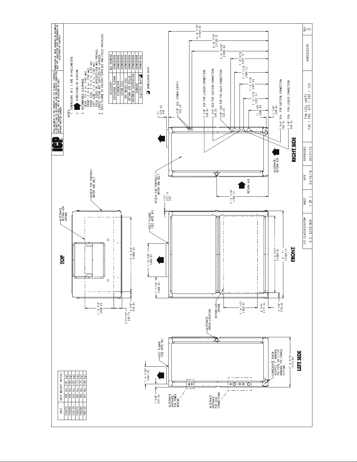
Fig. 1 — Unit Dimensions (6-10 Ton Units)
508 01 1603 01 Specifications subject to change without notice. 11
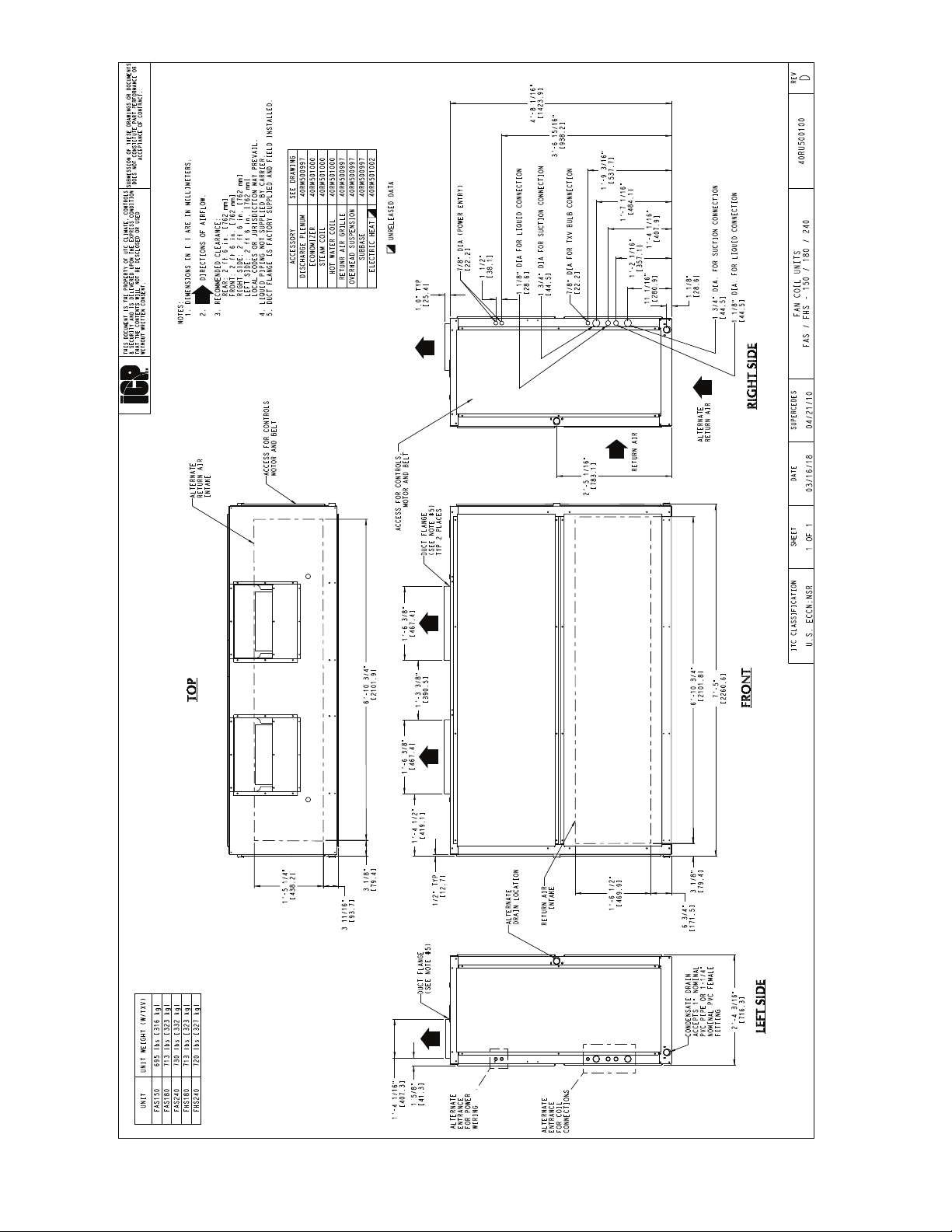
Fig. 2 — Unit Dimensions (12.5 to 20 tons)
12 Specifications subject to change without notice. 508 01 1603 01
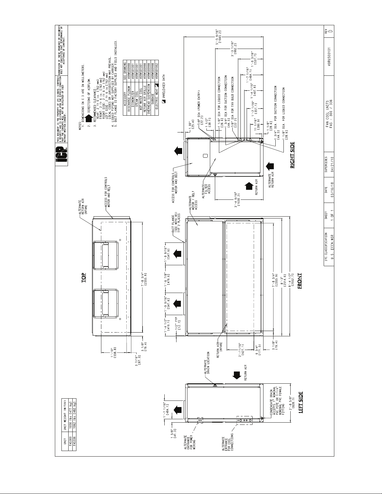
Fig. 3 — Unit Dimensions (25 and 30 tons)
508 01 1603 01 Specifications subject to change without notice. 13

MODEL SERIES
Position Number
Type
Voltage
Fan Motor Options
Indoor Coil
0 = Single Speed Indoor Fan Motor
2 = Two Speed Indoor Fan Motor Controller (VFD)
A = Standard - Unpainted
B = Painted cabinet (Gray)
A = Standard
Notes:
• All FAS072-150 units and FHS 072-120 units with a “M” voltage designation are triple voltage; i.e., 208/230/460-3-60.
FAS 180 units are also triple voltage in the “M” configuration unless the High Static motor option is used.
“M” voltage is not available on 2-speed indoor fan motor option.
• Single-phase 072 and 091 units designate standard motor and high static drive.
Painted Cabinet Options
A = Cu/Al
Future Use0 = Future Use
Eciency
072 = 6 Tons (1 circuit)
091 = 7.5 Tons (1 circuit)
120 = 10 Tons (2 circuit)
150 = 12.5 Tons (2 circuit) (FAS units only)
180 = 15 Tons (2 circuit)
240 = 20 Tons (2 circuit)
300 = 25 Tons (2 circuit) (FAS units only)
336 = 30 Tons (2 circuit) (FAS units only)
K = 208/230−1−60
H = 208/230−3−60
M = 460/208/230−3−60
L = 460−3−60
S = 575−3−60
A = Future Use
A = Standard Static Standard Efficiency Motor / Standard Drive
• 6 to 15 ton 208/230v, 460v, 575v-3-60, 6 and 7.5 ton 208/230-1-60, 1-speed
• all 2-speed
B = High St
atic Standard Efficiency Motor / High Drive
• 6 to 15 ton 208/230V, 460v, 6 to 10 ton 575v-3-60, 1-speed
• all 2-speed
D = Standard Static High Efficiency Motor / Standard Drive
• 20, 25, 30 ton all 3 phase
E = High Static High Efficiency Motor / High Drive
• 15 to 30 ton all 3 phase
F = R-410A Fan Coil Unit
A = Air Conditioning (Cooling Only)
H = Heat Pump
S = Standard Efficiency
Nominal Tonnage
Future Use
Fan Spee
d Controller
FAS09 1MAAA0 A0A
1
23
4
5
6
7
89
10 11
12
13
14
Unit Positioning
The unit can be mounted on the floor for vertical application with return air entering the face of the unit and supply
air discharging vertically through the top of the unit. The
unit can also be applied in a horizontal arrangement with
return air entering horizontally and the supply air discharging horizontally. When applying the unit in a horizontal arrangement, ensure the condensate drain pan is located at
the bottom center of the unit for adequate condensate disposal. See Fig. 6 for condensate connections for each unit
position.
Fig. 4 — Model Number Nomenclature
Typical positioning and alternate return air locations are
shown in Fig. 6. Alternate return air locations can be used
by moving the unit panel from the alternate return air location to the standard return air location. Refer to overhead
suspension accessory drawing (Fig. 7) for preferred suspension technique. The unit needs support underneath to
prevent sagging.
IMPORTANT: Do NOT attempt to install unit with
return air entering top panel of unit. Condensate will
not drain from unit.
14 Specifications subject to change without notice. 508 01 1603 01
 Loading...