

Intermec Trakker Antares 2415, Trakker Antares 2425, Trakker Antares 2435A, Trakker Antares 2455, Trakker Antares 2475 Programmer's Manual
...Page 1

Programmer's Guide
Native Terminal
Emulation
Page 2

Intermec Technologies Corporation
Corporate Headquarters Technical Communications Department
6001 36th Ave. W. 550 Second Street SE
Everett, WA 98203 Cedar Rapids, IA 52401
U.S.A. U.S.A.
www.intermec.com
The information contained herein is proprietary and is provided solely for the purpose of allowing customers
to operate and service Intermec-manufactured equipment and is not to be released, reproduced, or used for
any other purpose without written permission of Intermec.
Information and specifications contained in this document are subject to change without prior notice and do
not represent a commitment on the part of Intermec Technologies Corporation.
E 1995-2005 by Intermec Technologies Corporation. All rights reserved.
The word Intermec, the Intermec logo, Norand, ArciTech, CrossBar, Data Collection Browser, dcBrowser,
Duratherm, EasyCoder, EasyLAN, Enterprise Wireless LAN, EZBuilder, Fingerprint, i-gistics, INCA (under
license), InterDriver, Intermec Printer Network Manager, IRL, JANUS, LabelShop, Mobile Framework,
MobileLAN, Nor*Ware, Pen*Key, Precision Print, PrintSet, RoutePower, TE 2000, Trakker Antares, UAP,
Universal Access Point, and Virtual Wedge are either trademarks or registered trademarks of Intermec
Technologies Corporation.
Throughout this manual, trademarked names may be used. Rather than put a trademark (™ or ®) symbol in
every occurrence of a trademarked name, we state that we are using the names only in an editorial fashion,
and to the benefit of the trademark owner, with no intention of infringement.
There are U.S. and foreign patents pending.
Microsoft, Windows, and the Windows logo are registered trademarks of Microsoft Corporation in the
United States and/or other countries.
Bluetooth is a trademark of Bluetooth SIG, Inc., U.S.A.
ii Native Terminal Emulation Programmer’s Guide
Page 3

Document Change Record
This page records changes to this document. The document was originally released as Revision A.
Revision Date Description of Change
C 04/2003 Added Direct Connect port numbre, added Define Origin option, revised remap key
information, revised error tone information, added 2435A 48 -key keypad information,
added 2435A 31/32 column bar code information, removed paging keys information.
D 10/2003 Revised Radio Comm information for Trakker Antares terminals, revised Security Opts
menu option.
E 04/2004 Written for software version 7.39 or gerater. Added screen sizes and bar codes to Trakker
Antares terminals. Modified 248X screen size information.
F 03/2005 Added Back Tab key to 2435A terminal in Chapter 2, “Using the Terminal’s Keyboard.”
Revised the 2475, 2481, and 2486 terminal screen sizes and revised the appearance of
CUSTOM.DAT parameter information in Chapter 4, “Customizing Your Configuration.”
Changed “DCS 300” references to “Intermec Application Server.”
iiiNative Terminal Emulation Programmer’s Guide
Page 4

iv
Native Terminal Emulation Programmer’s Guide
Page 5

Contents
Before You Begin xvii............................................................
Safety Summary xvii......................................................
Safety Icons xviii..........................................................
Global Services and Support xix..............................................
WhoShouldReadthisGuide? xx............................................
Related Documents xx.....................................................
Contents
Donotrepairoradjustalone xvii......................................
First aid xvii......................................................
Resuscitation xvii..................................................
Energized equipment xvii............................................
Warranty Information xix............................................
Web Support xix...................................................
Telephone Support xix...............................................
1
Getting Started
Understanding Network Protocol Options 2...........................................
Setting Up the Terminal and the Network 2...........................................
Starting the Native Terminal Emulation Application 3...................................
Becoming Familiar With Native Terminal Emulation 3..................................
Performing a Quick Configuration 4................................................
Configuring the Native Application 5................................................
Using Advanced Features 5........................................................
Unsupported Commands and Functions 5............................................
Program Names 6...............................................................
1............................................................
Using the Terminal’s Keyboard
2
2415 Terminal 8................................................................
2415 Cursor Keys 8.......................................................
2415 Tab Keys 8.........................................................
2415 AID-Generating Keys 9...............................................
2415 Auto-Login Restart 9.................................................
7...........................................
vNative Terminal Emulation Programmer’sGuide
Page 6

Contents
2425 Terminal 10...............................................................
2425 Cursor Keys 10......................................................
2425 Tab Keys 10........................................................
2425 AID-Generating Keys 11..............................................
2425 Auto-Login Restart 11................................................
2435A Terminal 12..............................................................
Characters on the Keyboards 12..............................................
2435A Cursor Keys 12.....................................................
2435A Tab Keys 13.......................................................
2435A Standard Keys 13...................................................
2435A Function Keys 13...................................................
2435A AID-Generating Keys 14.............................................
2435A Auto-Login Restart 14...............................................
2435A 3270 Additional Functions 15.........................................
2455 Terminal 16...............................................................
2455 Cursor Keys 16......................................................
2455 Tab Keys 16........................................................
2455 AID-Generating Keys 17..............................................
2455 Auto-Login Restart 17................................................
2475 and 248X Terminals 18......................................................
2475 and 248X Cursor Keys 18..............................................
2475 and 248X Tab Keys 18................................................
2475 and 248X AID-Generating Keys 19......................................
2475 and 248X Auto-Login Restart 19........................................
6400 Computer 20..............................................................
Characters on the Keyboards 20..............................................
Using the 41-Key Keyboard 21..............................................
6400 Tab Keys 21........................................................
6400 Function Keys 22....................................................
6400 Auto-Login Restart 23................................................
5055 Data Collection PC 24.......................................................
Characters on the Keyboard 24..............................................
5055 Tab Keys 24........................................................
5055 Function Keys 25....................................................
5055 Auto-Login Restart 25................................................
59XX Terminal 26..............................................................
Characters on the Keyboard 26..............................................
59XX Function Keys 27....................................................
59XX Auto-Login Restart 27................................................
vi Native Terminal Emulation Programmer’s Guide
Page 7

Contents
17XX Terminal 28..............................................................
Characters on the Keyboards 28..............................................
37-Key Keyboard 29......................................................
17XX Tab Keys 30........................................................
17XX Function Keys 31....................................................
17XX Auto-Login Restart 31................................................
11XX Terminal 32..............................................................
Characters on the Keyboard 32..............................................
11XX Tab Keys 33........................................................
11XX Function Keys 33....................................................
11XX Auto-Login Restart 33................................................
3
Using the Terminal Emulation Menus
Function Keys 36...............................................................
Enter Key 36............................................................
Shift Keys 36............................................................
Y (“Yes”) Key 36.........................................................
Up and Down Arrows 37...................................................
Number Keys [0] through [9] 37.............................................
Display Annunciators 38...................................................
Display Position 0 38...............................................
Display Position 1 38...............................................
Display Position 2 39...............................................
Display Position 3 39...............................................
Display Position 4 39...............................................
Display Position 5 39...............................................
Display Position 6 39...............................................
Display Positions 1 through 3 39......................................
Display Positions 4 and 5 40..........................................
Display Positions 4 through 6 40......................................
Display Positions 4 through 8 40......................................
Display Positions 5 through 8 40......................................
Configuring TE Parameters 41.....................................................
KeySequencetoOpenMainMenu 41........................................
Opening the Main Menu 42................................................
2415, 2425, 2435A, 2455, 2475, 248X Menus 42.........................
6400, 5055, 59XX, 17XX, 11XX Menus 44..............................
1) Set Up Parameters 46....................................................
1) Communication 46...............................................
2) Barcode Parms (2415, 2425, 2435A, 2455, 2475, 248X) 51...............
2) Barcode Parms (6400, 5055, 59XX, 17XX, 11XX) 52....................
3) Protocol Opts 57................................................
4) Display Opts 71.................................................
5) Radio Comm (Blank for 2415, 2425, 2435A, 2455, 2475, 248X Terminals
without an 802.1x Supplicant Radio Driver) 73....................
6) Cold Start 74...................................................
7) More 74.......................................................
35...................................
viiNative TerminalEmulation Programmer’sGuide
Page 8

Contents
2) LCD Parms (Parameters) 75..............................................
1) LCD Contrast (59XX, 17XX) 75....................................
2) Screen Size (blank for 2480, 2485) 76................................
3) Screen Mode 82.................................................
4) Annunciators (Blank for 17XX, 11XX ) 84.............................
5) Backlight (59XX, 17XX) 84........................................
6) Key Uppercase 85................................................
7) Scroll Window 85................................................
3) Beeper Setup (6400, 5055, 59XX, 17XX, 11XX) 86............................
1) Key Click (6400, 5055, 59XX, 17XX, 11XX) 86........................
2) Error Tone 87...................................................
3) Beeper Select (6400, 5055, 17XX, 11XX) 87...........................
4) Tests 88..............................................................
1) Peripherals 88...................................................
2) Converters (59XX) 91.............................................
3) Memory View (6400, 5055, 17XX, 11XX) 91..........................
4) Packet Driver (6400, 5055, 59XX, 17XX, 11XX) 92.....................
5) Numbers 93....................................................
6) Timed Numbers 93..............................................
5) Version Info (Information) 93.............................................
6) Exit Menus 94.........................................................
7) More (Main Menu 2) 95.................................................
1) Keyboard Opts 95................................................
2) Save Parms (Parameters) 95........................................
3) Cloning Opts (59XX, 17XX, 11XX) 96...............................
4) Session Menu (2415, 2425, 2435A, 2455, 2475, 248X with WTP, 6400, 5055,
59XX, 17XX, 11XX) 98......................................
4
Restarting Terminal Emulation 98..................................................
2415, 2425, 2435A, 2455, 2475, 248X Terminals 100..................................
6400 Computer 100.............................................................
Opening the Main Menu 100...............................................
To Exit Emulation Mode and Return to DOS 101...............................
5055 Data Collection PC 101......................................................
Programs to Create Terminal Emulation Menus 102..............................
Opening the Main Menu 103...............................................
To Exit Emulation Mode and Return to DOS 103...............................
Customizing Your Configuration
Using the Auto-Login Feature 106..................................................
Developing Auto-Login Script Files 106.......................................
Commands 106....................................................
Search Strings 107..................................................
Control Characters 108..............................................
105.......................................
viii Native Terminal Emulation Programmer’s Guide
Page 9

Contents
Loading the Auto -Login Script File 108........................................
2415, 2425, 2435A, 2455, 2475, 248X Terminals 108.....................
6400, 5055 Terminals 109...........................................
59XX, 17XX, 11XX Terminals 109....................................
Disabling the Auto-Login Feature 110.........................................
2415, 2425, 2435A, 2455, 2475, 248X Terminals 110.....................
6400, 5055 Terminals 110...........................................
59XX, 17XX, 11XX Terminals 110....................................
Sample Auto-Login Script Files 111...........................................
Auto-Login Restart 113....................................................
Creating a Custom Parameter Set-Up File 114.........................................
CONFIG.DAT Settings 114................................................
CONFIG.DAT Syntax 114..........................................
CONFIG.DAT Parameter Formats 115.................................
Verifying Your CONFIG.DAT Configuration 116........................
CONFIG.DAT Parameters and Qualifiers 116............................
Changing Text 133..............................................................
Preinitializing the Native TE Program 134............................................
Remapping the Terminal’s Keys 135.................................................
Remapping a Key or Two-Key Sequence 135....................................
Creating a Macro 136.....................................................
Nesting 137.............................................................
Remapping Keys for Each Session 137.........................................
Key Code Table 137......................................................
Remapping Characters 140........................................................
Substituting National Characters 141................................................
Creating the File 141......................................................
National Replacement Character Sets 142......................................
Example 143............................................................
Downloading Files 144...........................................................
2415, 2425, 2435A, 2455, 2475, 248X Terminals 144............................
6400, 5055 Terminals 144..................................................
Reprogramming Flash Memory 145....................................
Prerequisites for INTERLNK Flash Update 145...........................
INTERLNK Installation 145.........................................
INTERLNK and INTERSVR 146.....................................
59XX, 17XX, 11XX Terminals 146...........................................
ixNative Terminal Emulation Programmer’sGuide
Page 10

Contents
Using CHECKCFG to Compile and Decompile Custom Configurations 146..........
Converting Files from ASCII to Binary 146..............................
Converting Files from Binary to ASCII 147..............................
Listing Parameters and Values 147.....................................
Using FLSHCONV.EXE to Build Customized HEX Files 147...............
Locating and Appending .EXE Files 148.................................
Appending Data Files To Intel-Hex Files 148.............................
Downloading a Hex File 149.........................................
5
Intermec Application Server and Gateway Commands
CMT (Return Parameter Values) 152................................................
CMT, (Set All Parameters) 153.....................................................
CMT0 (Set Response Delay) 155...................................................
CMT1 (Set Data Time-Out) 156...................................................
CMT2 (Interactive Mode) 157.....................................................
CMT4 (Add Line Feed to Responses) 158............................................
CMT5 (Set Gap Time-Out) 159...................................................
CMT8 (Set Data Error Checking) 160...............................................
CMT10 (Enable Extended Response Mode) 161.......................................
151................
CMT13 (Automatically Enable Terminal) 162.........................................
CMT21 (One-Character Address Mode) 163..........................................
CMT22 (Multiple Buffering Mode) 164..............................................
CMT27 (6910 IGAP Operating Mode) 166...........................................
CMTI (Restore Default Parameters) 167.............................................
?(GetTransmitMessageStatus) 168................................................
E (Enable Terminals) 169.........................................................
R(Read) 170..................................................................
x Native Terminal Emulation Programmer’s Guide
Page 11

Contents
T (Repeat Response) 172.........................................................
F (Return Terminal Power-Up Type) 173.............................................
DME (Echo-Back Diagnostics) 174.................................................
DMP (Reset) 175...............................................................
DMV (Send Software Version) 176..................................................
Normal Communication Flow 177..................................................
Compatibility With Legacy Systems 178..............................................
Write Display Errors 179.........................................................
6
Terminal Commands
G (Reset Terminal) 182..........................................................
StD/ (Set Terminal Parameters) 183.................................................
WtB (Audio Annunciator) 187.....................................................
WtD/ (Write Display) 188........................................................
Command Extensions 190........................................................
WtD// (Extended Write Display) 192................................................
WtD/ \yS (Download Table) 194...................................................
Input Field Control Byte 195................................................
Rules for Designing Tables 196..............................................
WtD/ \y (Display Table) 197......................................................
181....................................................
WtD/ \yT (Download and Display Table) 199.........................................
WtD/ \yU (Update Table) 201.....................................................
Replacing Pairs Together 203................................................
Restrictions 203..........................................................
Replacing the Prompt Field 203..............................................
Replacing the Field Only 204...............................................
WtD/ \yV (Update and Display Table) 205...........................................
xiNative Terminal Emulation Programmer’s Guide
Page 12

Contents
WtD/ \F (Set Terminal Function Keys) 208...........................................
WtD/ \B (Set Bank) 209..........................................................
WtD/ \BU (Update Bank) 210.....................................................
WtD/ \BE (Erase Bank) 211.......................................................
WtD/ \C (Set Screen Mode) 212...................................................
WtD/ \P (Print) 213.............................................................
WtD/ \PM (Port in Use Message) 215...............................................
WtD/ \PS (RS-232 Port Options) 217...............................................
A
WtD/ \PG (Get Data from an External Device) 218.....................................
WtD/ \PF (Send a nd Get Data from an External Device) 221.............................
WtD/ \yP (Print Table) 223.......................................................
WtD/ \yR (Update and Print Table) 224.............................................
WtD/\yQ(Update,Display,andPrintTable) 226.....................................
WtD/ \T (Tone) 228............................................................
DtV (Terminal Emulation Version) 229..............................................
DtE (Echo-Back Diagnostic) 230...................................................
Bar Code Scanning
DK, Display Column Spacing 232..................................................
2415 and 2425 Terminal Displays 232........................................
10 Columns 232...................................................
12 Columns 232...................................................
17 Columns 233...................................................
20 Columns 234...................................................
22 Columns 234...................................................
26 Columns 235...................................................
32 Columns 236...................................................
231.......................................................
xii Native Terminal Emulation Programmer’s Guide
Page 13

Contents
2435A Terminal Display 236................................................
9or10Columns 236...............................................
12 Columns 237...................................................
17 Columns 238...................................................
19 or 20 Columns 239..............................................
22 Columns 240...................................................
26 Columns 241...................................................
31 or 32 Columns 242..............................................
2455 Terminal Display 243.................................................
20 Columns 243...................................................
33 Columns 243...................................................
40 Columns 244...................................................
53 Columns 244...................................................
80 Columns 244...................................................
2475 and 248X Terminal Displays 245........................................
10 Columns 245...................................................
12 Columns 245...................................................
17 Columns 246...................................................
20 Columns 247...................................................
22 Columns 247...................................................
26 Columns 248...................................................
32 Columns 249...................................................
40 Columns 249...................................................
53 Columns 249...................................................
64 Columns 249...................................................
B
Cursor Keys 250................................................................
Tab Keys 250..................................................................
AID-Generating Keys 250.........................................................
Auto-Login Restart 253...........................................................
Native Additional Functions 254...................................................
Encoded Code 39 254............................................................
Terminating Keys 256.....................................................
Escape Characters 256.....................................................
Overriding Auto Tab Scan and Auto Enter Scan 257..............................
Bar Code Symbologies
Bar Code Algorithms 260.........................................................
UPC 261......................................................................
259..................................................
EAN 262......................................................................
xiiiNative Terminal Emulation Programmer’sGuide
Page 14

Contents
Codabar 262...................................................................
Code 11 262...................................................................
Code 39 263...................................................................
Encoded Code 39 (Concatenation) 263..............................................
Encoded Code 39 (Full ASCII) 263.................................................
Code 93 264...................................................................
Code 128 264..................................................................
I 2 of 5 (Interleaved) 266.........................................................
S2of5(Standard2of5) 266......................................................
C
D
Plessey 267....................................................................
MSI Code (Variant of Plessey) 267..................................................
Terminal Font Set Table
Native Sockets
Communication Basics 280........................................................
Host Programming 281..........................................................
Coding the Application 281.................................................
Response Formats 282.....................................................
Error Messages 282.......................................................
Normal Communication 283......................................................
Coding the Application 283.................................................
Syntax for Terminals 283...................................................
WtD/ (Write Display) Command 283..................................
Native Mode Responses 284..........................................
269.................................................
279...........................................................
Configuration 284..............................................................
Demonstration Program 285.......................................................
xiv Native Terminal Emulation Programmer’s Guide
Page 15

I
Contents
Index
General Index 294...............................................................
Files Index 310.................................................................
xvNative Terminal Emulation Programmer’sGuide
Page 16

Contents
xvi Native Terminal Emulation Programmer’s Guide
Page 17

Before You Begin
Safety Summary
Before You Begin
This section provides you with safety information, technical su pport
information, and sources for additional product information.
Your safety is extremely important. Read and follow all warnings and
cautions in this document before handling and operating Intermec
equipment. You can be seriously injured, and equipment and data can be
damaged if you do not follow the safety warnings and cautions.
Donotrepairoradjustalone
Do not repair or adjust energized equipment alone under any
circumstances. Someone capable of providing first aid must always be
present for your safety.
First aid
Always obtain first aid or medical attention immediately after an injury.
Never neglect an injury, no matter how slight it seems.
Resuscitation
Begin resuscitation immediately if someone is injured and stops breathing.
Any delay could result in death. To work on or near high voltage, you
should be familiar with approved industrial first aid methods.
Energized equipment
Never work on energized equipment unless authorized by a responsible
authority. Energized electrical equipment is dangerous. Electrical shock
from energized equipment can cause death. If you must perform
authorized emergency work on energized equipment, be sure that you
comply strictly with approved safety regulations.
xviiNative Terminal Emulation Programmer’sGuide
Page 18

Before You Begin
Safety Icons
This section explains how to identify and understand dangers, warnings,
cautions, and notes that are in this manual. You may also see icons that tell
you when to follow ESD procedures and when to take special precautions
for handling optical parts.
A warning alerts you of an operating procedure, practice, condition,
or statement that must be strictly observed to avoid death or serious
injury to the persons working on the equipment.
Avertissement: Un aver tissement vous avertit d’un e procédure de
fonctionnement, d’une méthode, d’un état ou d’un rapport qui doit
être strictement respecté pour éviterl’occurrencedemortoude
blessures graves aux personnes manupulant l’équipement.
A caution alerts you to an operating procedure, practice, condition, or
statement that must be strictly observed to prevent equipment damage
or destruction, or corruption or loss of data.
Attention: Une précaution vous avertit d’une procédure de
fonctionnement, d’une méthode, d’un état ou d’un rapport qui doit
être strictement respecté pour empêcher l’endommagement ou la
destruction de l’équipement, ou l’altération ou la perte de don n ées.
Note: Notes either provide extra information about a topic or contain
special instructions for handling a particular condition or set of
circumstances.
xviii Native Terminal Emulation Programmer’s Guide
Page 19

Global Services and Support
Warranty Information
To understand the warranty for your Intermec product, visit the Intermec
web site at www.intermec.com and click Service & Support.TheIntermec
Global Sales & Service page appears. From the Service & Support menu,
move your pointer over Support,andthenclickWarranty.
Disclaimerofwarranties:Thesamplecodeincludedinthisdocumentis
presented for reference only. The code does not necessarily represent
complete, tested programs. The code is provided “as is with all faults.” All
warranties are expressly disclaimed, including the implied warranties of
merchantability and fitness for a particular purpose.
Web Support
Visit the Intermec web site at www.intermec.com to download our cur rent
manuals in PDF format. To order printed versions of the Intermec
manuals, contact your local Intermec representative or distributor.
Visit the Intermec technical knowledge base (Knowledge Central) at
intermec.custhelp.com to review technical information or to request
technical support for your Intermec product.
Before You Begin
Telephone Support
These services are available f rom Intermec Technologies Corporation.
In the U.S.A. and Canada
call 1-800-755-5505
Service Description
Factory Repair and
On-site Repair
Technical Su pport Get technical support on your
Service Contract
Status
Schedule Site Surveys
or Installations
Ordering Products Talk to sales administration,
Request a return authorization
number for authorized service
center repair, or request an
on-site repair technician.
Intermec product.
Inquire about an existing
contract, renew a contract, or ask
invoicing questions.
Schedule a site survey, or request
a product or system installation.
place an order, or check the
status of your order.
Outside the U.S.A. and Canada, contact your local Intermec
representative. To search for your local representative, from the Intermec
web site, click Contact.
and choose this option
1
2
3
4
5
xixNative Terminal Emulation Programmer’s Guide
Page 20

Before You Begin
WhoShouldReadthisGuide?
This guide provides you with information about the Native terminal
emulation application, and how to install, configure, operate, maintain,
and troubleshoot the application.
Related Documents
This table contains a list of related Intermec documents and part numbers.
Manual Part #
1100 Series Data Terminal User’s Guide 961-047-069
5020 Data Collection PC User’s Ma nual 068975-002
5055 Data Collection PC User’s Guide 961-054-017
5900 Series User’s Guide 961-047-121
The Bar Code Book 051241
EZBuilder Ge tti ng Started Guide 066450
EZBuilder Tutorial 066449
Intermec Application Server User’s Guide 072242
MobileLANtaccess 21xx System Manual 067150
PEN*KEY Model 6400 User’s Guide 961-047-098
RT1700 Radio Terminal User’s Guide 961-047-068
TE 2000 3270 Terminal Emulation Programmer’s Guide 977-055-003
TE 2000 5250 Terminal Emulation Programmer’s Guide 977-055-004
TE 2000 VT/ANSI Terminal Emulation Programmer’s Guide 977-055-005
TRAKKER Antares 241X Hand-Held Terminal User’s Manual 069538
TRAKKER Antares 2420 and 2425 Hand-Held Terminal User’s Manual 064024
TRAKKER Antares 243X Hand-Held Terminal User’s Manual 071791-001
TRAKKER Antares 2455 Vehicle Mount Terminal User’s Manual 067358
TRAKKER Antares 2475 Vehicle-Mount Terminal User’s Manual 072383
TRAKKER Antares 248X Stationary Terminal User’s Manual 066960
TRAKKER Antares Application Development Tools System Manual 064433
TRAKKER Antares Optical Link Adapter Quick Reference Guide 065826
TRAKKER Antares TD2400 Communications Dock Quick Reference Guide 065555
TRAKKER Antares TD2410 Communications Dock Quick Reference Guide 069552
The Intermec web site at www.intermec.com contains our documents that
you can download in PDF format.
To order printed versions of the Intermec manuals, contact your local
Intermec representative or distributor.
xx Native Terminal Emulation Programmer’s Guide
Page 21

Getting Started
1
This chapter introduces the Native terminal emulation application.
1Native Terminal Emulation Programmer’sGuide
Page 22

Getting StartedChapter —1
Understanding Network Protocol Options
Native Terminal Emulation applications for the Enterprise Wireless
LANt system use one of the following network protocol options:
S TCP/IP
The terminal communicates through an IntermecRaccess point, which
is directly connected to the host computer on an Ethernet or a token
ring network.
S WTP
The terminal communicates with the host computer through the Intermec Application Server, Intermec access point, or other Intermec gateways.
For network configuration options, refer to your terminal’s user manual.
Setting Up the Terminal and the Network
Before you can start using the Native Terminal Emulation application on
your terminal, you need to do the following:
1 Set up your terminal.
Set-up includes charging and installing the battery pack and turning on
the terminal for the first time. For instructions, refer to your terminal’s
user manual.
Note: Battery packs do not apply to all terminals. Vehicle mount and
stationary terminals are powered via an external source.
2 Configure your terminal and the network.
To use RF communications on the terminal, you need to:
a Configure the Intermec Application Server (WTP), other Intermec
gateways (WTP), or host (TCP/IP).
b Configure the access point. This does not apply to the 2480/2481 Ter-
minal, which contains an Ethernet NIC instead of a radio.
c Configure the network parameters on the terminal.
Forinstructions,refertoyourterminal’susermanual.
3 Verify that your terminal is communicating correctly with the access
point, gateway, or host.
To verify that your terminal is communicating correctly, refer to the
terminal’s user manual for instructions.
2 Native Terminal Emulation Programmer’s Guide
Page 23

Starting the Native Terminal Emulation Application
You are ready to start your application once the terminal has been set up,
the terminal and the network have been configured, and communications
have been established with the gateway and access point or host.
To start your application:
Turn on the terminal. Wait a few seconds while the initialization screens
(below) clear and the application starts.
COPR. 1991-2005
INTERMEC. ALL
RIGHTS RESERVED
V<version number>
<release date>
TE2000(TM)
Getting Started—Chapter 1
<program name> <version>
Host: <host name>
<emulation type>
Note: If your application does not start after a few seconds, you may not
have configured the terminal correctly. For help, refer to your terminal’s
user manual.
You can now do one of the following:
S Become f amiliar with Native TE if you have not previously used it.
S Perform a quick configuration.
S Configure your Native TE application.
S Customize your Native TE application.
Becoming Familiar With Native Terminal Emulation
If you have not previously used Native TE, see Chapter 3, “Using the Terminal’s Keyboard,” to become familiar with your terminal’s keyboard and
the keys you need to press to perform Native commands. See Chapter 6,
“Terminal Commands,” to understand Native commands.
3Native Terminal Emulation Programmer’sGuide
Page 24

Getting StartedChapter —1
Performing a Quick Configuration
Note: For Terminal Emulation Version 6.60 or greater, the default data
stream is “VT/ANSI.”
1 Change the data stream to Native. The default data stream is “Native”
for the 6400 (WTP), 5055 (WTP), 11XX, 17XX, and 59XX Terminals.
The default data stream f or 2415, 2425, 2435A, 2455, 2475, 248X,
and IP terminals is “3270.”
a Access the terminal emulation configuration menus by pressing the
following keys, then choose 1) Set-up Parms from the Main Menu.
Terminal Key Sequence
2415
2425
2435A
2455, 2475, 248X
6400 [Gold] [Blue]
5055 [Blue] [M] or [ALT] [M]
59XX [Brown] [Space]
17XX, 11XX [Gold] [Black]
)!
(55-key keyboard)
(5
(37-key keyboard)
(!
rl
[Green]
rl
(¡
(57-key keyboard)
>
[Orange]>(48-key keyboard)
(39-key function numeric keyboard)
Note: Press a number to select a menu option, then press [Enter] to
return to a previous menu.
b At the Enter Password prompt, enter cr52401.
On 17XX (37-key) Terminals, the password is: F12F1152401
c From the Set-up Parms menu, select 3) Protocol Opts,
2) Data Stream,then7) Native.
2 From the Main Menu, select 7) More,then2) Save Parms.
3 At the Enter Password prompt, type cr52401, then press enter.
On 17XX (37-key) Terminals, the password is: F12F1152401
4 From the Main Menu, select 6) Exit Menus.
Note: For WTP devices, you should also set a terminal number.
5 Log in to a TE session, then use the terminal to collect/transmit data.
4 Native Terminal Emulation Programmer’s Guide
Page 25

Configuring the Native Application
You can use the terminal’s TE configuration menus to configure site-specific operational parameters, including WTP or TCP/IP communications,
terminal emulation options, and the Main Menu password. For information about configuring the terminal, see Chapter 3, “Using the Terminal
Emulation Menus.”
Using Advanced Features
You can customize the standard Native TE program to do the following:
For more information, see Chapter 4, “Customizing Your Configuration.”
S Use the auto-login feature to send the same login information each time
you login to the host.
S Create a custom parameter set-up file.
S Change the text of TE configuration menus or system messages.
S Preinitialize the Native TE program
Getting Started—Chapter 1
Unsupported Commands and Functions
Native TE for the 2415, 2425, 2435A, 2455, 2475, and 248X Terminals
does not support the following commands and functions, which were supported in previous versions.
S End (viewport)
Moved the window/viewport to the end of the last line displayed on the
TE screen.
S Erase Field
Erased all characters in the field where the cursor was positioned.
S Erase Last Word
Erased all characters from the cursor back to the start of a word or a
space on the screen.
S Fast Cursor Right or Left
Moved the cursor two positions to the right or left rather than one.
S Home (viewport)
Moved the window or viewport to the top left corner of the TE screen.
S Reshow
Resent a screen image from the locally maintained host buffer to refresh
the terminal screen.
S Status
Toggled the terminal’s screen between the status line display and the
normal field input display.
S Status line messages
Reported the operating status of the terminal and host system.
5Native Terminal Emulation Programmer’sGuide
Page 26

Getting StartedChapter —1
S Dual sessions
Not supported in Trakker Antares TCP terminals.
If you scan the bar code for an unsupported command, the bar code data
is read into the terminal. If you press the key sequence for the command,
thesequenceisignored.
Program Names
The following chart lists TE options and program names.
Note: Native TE does not support SST (Spread Spectrum Transmission)
or regular UHF. “S-UHF” is synthesized UHF.
Model Option Program Name
2415, 2425, 2435A, 2455, 2475, 248X TE/WTP/2.4 GHz OpenAir
TE/WTP/802.11
TE/IP/2.4 GHz OpenAir
TE/IP/802.11
6400 TE/WTP/2.4 GHz OpenAir
TE/WTP/802.11
TE/WTP/900 MHz Falcon
TE/IP/2.4 GHz OpenAir
TE/IP/802.11
5055 TE/WTP/2.4 GHz OpenAir
TE/WTP/802.11
TE/IP/2.4 GHz OpenAir
TE/IP/802.11
59XX TE/WTP
TE/WTP
TE/WTP/2.4 GHz OpenAir
TE/WTP/900 MHz Falcon
TE/WTP/S-UHF
17XX TE/WTP
TE/WTP
TE/WTP/2.4 GHz OpenAir
TE/WTP/900 MHz Falcon
TE/WTP/S-UHF
11XX TE/WTP
TE/WTP
TE/WTP/2.4 GHz OpenAir
TE/WTP/900 MHz Falcon
TE/WTP/S-UHF
51-key keyboard 41-key keyboard
FWP640H0 FWP640H4
FWP640H0 FWP640H4
FWP640H0 FWP640H4
FWP64TH0 FWP64TH4
FWP64TH0 FWP64TH4
57-key keyboard 37-key keyboard
FWP170H0 FWP170H3
FWP174H0 FWP174H3
FWP178H0 FWP178H3
FWP176H0 FWP176H3
FWP171H0 FWP171H3
FWP240H0
FWP650H0
FWP650H0
FWP65TH0
FWP65TH0
FWP592H0
FWP594H0
FWP598H0
FWP596H0
FWP591H1
FWP110H0
FWP114H0
FWP118H0
FWP116H0
FWP111H0
6 Native Terminal Emulation Programmer’s Guide
Page 27

Using the Terminal’s
2
Your terminal has a special keyboard that contains most of the keys available on your Native terminal keyboard. Use the keyboard to Enter data in
the TE screens.
The keys on the keyboard have their main character or operation marked
directly on the key itself. To access that character or operation, just press
the key.
Keyboard
You can access TE commands and functions printed above the keys by
pressing key combinations.
7Native Terminal Emulation Programmer’sGuide
Page 28

Using the Terminal’s KeyboardChapter —2
2415 Terminal
For help with using the keyboard, refer to the TRAKKER Antares 241X
Hand-Held Terminal User’s Manual (P/N 069538).
55-Key Keyboard
Function
Left Key
Shift Key
Your 2415 Terminal has either a 55-key (left) or a 37-key (right) keyboard as shown in this illustration.
Function
Right Key
Control Key
Function
Left Key
Shift Key
37-Key Keyboard
2415 Cursor Keys
Function
Right Key
Control Key
To Enter Press the Keys
Window/viewport up
Window/viewport down
Window/viewport right
Window/viewport left
=
>
(>
(=
2415 Tab Keys
To Enter Press the Keys
Back Tab
Forward Tab
8 Native Terminal Emulation Programmer’s Guide
(;
;
Page 29

2415 AID-Generating Keys
To Enter 55-Key Keyboard 37-Key Keyboard
Clear
F1
F2
F3
F4
F5
F6
F7
F8
F9
F10
F11
F12
F13
F14
F15
F16
F17
F18
F19
F20
F21
F22
F23
F24
Using the Terminal’s Keyboard—Chapter 2
Press the Keys
)9 ?=
! !
@@
# #
$$
(!
b
(@ c
(#
d
($ e
)A f
)B g
)C h
)D i
)E ?!
)F ?@
)G ?#
)H ?$
)I ?b
)J ?c
)K ?d
)L ?e
)M ?f
)N ?g
)O ?h
)P ?i
2415 Auto-Login Restart
To Enter Auto-Login Restart, scan the following bar code (also in Appendix A, “Bar Code Scanning”).
Auto-Login Restart
*/EALRS*
*%ALRS*
9Native Terminal Emulation Programmer’sGuide
Page 30

Using the Terminal’s KeyboardChapter —2
2425 Terminal
For help with using the keyboard, refer to the TRAKKER Antares 2420
and 2425 Hand-Held Terminal User’s Manual (P/N 064024).
2425 Cursor Keys
Function Left
(FnL) Key
Shift Key
This illustration shows the keyboard for the 2425 Terminal.
To Enter Press the Keys
Window/viewport up
Window/viewport down
Window/viewport right
Window/viewport left
Function Right
(FnR) Key
Control Key
)[
){
)}
)]
2425 Tab Keys
To Enter Press the Keys
Back Tab
Forward Tab
10 Native Terminal Emulation Programmer’s Guide
)<
<
Page 31

2425 AID-Generating Keys
To Enter Press the Keys
Clear
F1
F2
F3
F4
F5
F6
F7
F8
F9
F10
F11
F12
F13
F14
F15
F16
F17
F18
F19
F20
F21
F22
F23
F24
Using the Terminal’s Keyboard—Chapter 2
(W
!
@
#
$
%
)!
)@
)#
)$
)%
(A
(B
(C
(D
(E
(F
(G
(H
(I
(J
(K
(L
(M
(N
2425 Auto-Login Restart
To Enter Auto-Login Restart, press (%or scan the following bar code
(also in Appendix A, “Bar Code Scanning”).
Auto-Login Restart
*/EALRS*
*%ALRS*
11Native Terminal Emulation Programmer’sGuide
Page 32

Using the Terminal’s KeyboardChapter —2
2435A Terminal
For help with using the keyboard, refer to the TRAKKER Antares 243X
Hand-Held Terminal User’s Manual (P/N 071791-001).
57-Key Keyboard
Your 2435A Terminal has either a 57-key (left), a 48-Key (middle), or a 39-key (right) keyboard as shown in this illustration.
48-Key Keyboard
39-Key Keyboard
Characters on the Keyboards
The special characters and functions printed above the keys are colorcoded to correspond with the matching shift keys. The shift keys are:
[Orange]
[Green]
Press Orange>plus a key to type a character or do an operation printed in
orange on the overlay.
Press Green>plus a key to type a character or do an operation printed in
green on the overlay.
2435A Cursor Keys
Press the Keys
To Enter 57-Key Keyboard 48-Key Keyboard
Window/viewport up
Window/viewport down
Window/viewport right
Window/viewport left
lu
ld
lb
la
Orange>,
Orange>,
Orange>,
Orange>,
A lu
B ld
F lb
E la
39-Key Function
Numeric Keyboard
12 Native Terminal Emulation Programmer’s Guide
Page 33

2435A Tab Keys
Press the Keys
To Enter 57-Key Keyboard 48-Key Keyboard
Forward Tab
Back Tab Not applicable
lb : lb
:
^
2435A Standard Keys
Press the Keys
To Enter 57-Key Keyboard 48-Key Keyboard
0–9
Symbols
0–9 0–9 0–9
w
plus corresponding key
?
plus corresponding key
Using the Terminal’s Keyboard—Chapter 2
39-Key Function
Numeric Keyboard
Not applicable
39-Key Function
Numeric Keyboard
w
plus corresponding key
2435A Function Keys
Press the Keys
To Enter 57-Key Keyboard 48-Key Keyboard
Backspace
Caps Lock
Ctrl
Return
Shift
Space bar
n \ n
lr
c
Orange>,
Not supported.
^ lr
v ; v
w ^ w
s _ s
39-Key Function
Numeric Keyboard
c
13Native Terminal Emulation Programmer’sGuide
Page 34

Using the Terminal’s KeyboardChapter —2
2435A AID-Generating Keys
Press the Keys
To Enter 57-Key Keyboard 48-Key Keyboard
F1
F2
F3
F4
F5
F6
F7
F8
F9
F10
F11
F12
F13
F14
F15
F16
F17
F18
F19
F20
F21
F22
F23
F24 rR
Clear r8
g
h
i
j
k
o
rA
rB
rC
rD
rE
rF
rG
rH
rI
rJ
rK
rL
rM
rN
rO
rP
rQ
Orange>,
Orange>,
Orange>,
Orange>,
Orange>,
Orange>,
Orange>,
Orange>,
Orange>,
Orange>,
Green>,
Green>,
Green>,
Green>,
Green>,
Green>,
Green>,
Green>,
Green>,
Green>,
Orange>,
Green>,
Orange>,
Green>,
Green>,
1 g
2 h
3 i
4 j
5 k
6 o
7 m
8 p
9 q
0 [
1 \
2 ]
3 rg
4 rh
5 ri
6 rj
7 rk
8 ro
9 rm
0 rp
: rq
: r[
_ r\
_
P
39-Key Function
Numeric Keyboard
r]
r8
2435A Auto-Login Restart
To Enter Auto-Login Restart, press r
39-key function numeric keyboards; press Green>,
keyboard,orscanthefollowingbarcode(alsoinAppendixA,“Bar Code
Scanning”).
Auto-Login Restart
*/EALRS*
*%ALRS*
14 Native Terminal Emulation Programmer’s Guide
v
on the 57-key keyboard and
;
on the 48-key
Page 35

2435A 3270 Additional Functions
To access the TE configuration menus, press rlon the 57-key keyboard and 39-key function numeric keyboards, or press Green >,
Orange > on the 48-key keyboard.
Using the Terminal’s Keyboard—Chapter 2
15Native Terminal Emulation Programmer’sGuide
Page 36

Using the Terminal’s KeyboardChapter —2
2455 Terminal
For help with using the keyboard, refer to the TRAKKER Antares 2455
Vehicle-Mount T erminal User’s Manual (P/N 067358).
Note: You must use the 2455 keyboard (P/N 067028) with the TE applications.
Backspace Key
Shift Key
This illustration shows the keyboard for the 2455 Terminal.
Control Key
2455 Cursor Keys
To Enter Press the Keys
Window/viewport up
Window/viewport down
Window/viewport right
Window/viewport left
2455 Tab Keys
To Enter Press the Keys
Back Tab
Forward Tab
Function
Left Key
)[
){
)}
)]
)<
<
Function
Right Key
16 Native Terminal Emulation Programmer’s Guide
Page 37

2455 AID-Generating Keys
To Enter Press the Keys
Clear
F1
F2
F3
F4
F5
F6
F7
F8
F9
F10
F11
F12
F13
F14
F15
F16
F17
F18
F19
F20
F21
F22
F23
F24
Using the Terminal’s Keyboard—Chapter 2
(W
¡
¢
£
§
¶
)¡
)¢
)£
)§
)¶
(A
(B
(C
(D
(E
(F
(G
(H
(I
(J
(K
(L
(M
(N
2455 Auto-Login Restart
To Enter Auto-Login Restart, press (¶or scan the following bar code
(also in Appendix A, “Bar Code Scanning”).
Auto-Login Restart
*/EALRS*
*%ALRS*
17Native Terminal Emulation Programmer’sGuide
Page 38

Using the Terminal’s KeyboardChapter —2
2475 and 248X Terminals
Forhelpwithusingthekeyboard,refereithertotheTrakker Antares 2475
Vehicle-Mount T erminal User’s Manual (P/N: 072383) or the TRAKKER
Antares 248X Stationary Terminal User’s Manual (P/N 066960).
This illustration shows the keyboard for the 2475 and 248X Terminals.
2475 and 248X Cursor Keys
To Enter Press the Keys
Window/viewport up
Window/viewport down
Window/viewport right
Window/viewport left
Control Key
Function
Left Key
)¥
)†
)ª
)–
Backspace Key
Function
Right Key
Shift Key
2475 and 248X Tab Keys
To Enter Press the Keys
Back Tab
Forward Tab
18 Native Terminal Emulation Programmer’s Guide
)ø
ø
Page 39

2475 and 248X AID-Generating Keys
To Enter Press the Keys
Clear
F1
F2
F3
F4
F5
F6
F7
F8
F9
F10
F11
F12
F13
F14
F15
F16
F17
F18
F19
F20
F21
F22
F23
F24
)b
¡
¢
£
§
¶
)¡
)¢
)£
)§
)¶
(F
(G
(H
(J
(K
(L
(r
(
[quotation mark]
(Z
(X
(C
(V
(B
(N
Using the Terminal’s Keyboard—Chapter 2
2475 and 248X Auto-Login Restart
To Enter Auto-Login Restart, press (¶or scan the following bar code
(also in Appendix A, “Bar Code Scanning”).
Auto-Login Restart
*/EALRS*
*%ALRS*
19Native Terminal Emulation Programmer’sGuide
Page 40

Using the Terminal’s KeyboardChapter —2
6400 Computer
For help with the keyboard, see the PEN*KEY Model 6400 User’s Guide
(P/N 961-047-093).
51-Key Keyboard
Your 6400 Computer has either a 51-key (left) or a 41-key (right) keyboard as shown.
Characters on the Keyboards
41-Key Keyboard
Unlabeled Key Colors:
Blue
Gold
The special characters and functions printed above the keys are colorcoded to correspond with the matching shift keys. The shift keys are:
[Green] The Green [SHFT] puts the keyboard into green shift mode.
[Gold] Press [Gold] plus a key to type a character or do an operation printed in gold
on the overlay.
[Blue] Press [Blue] plus a key to do operations printed in blue on the overlay.
The 51-key keyboard has two gray, unlabeled keys in the bottom row.
These are the keys’ functions when they are unshifted (in primary plane):
Gray key with “Z” printed above it is the letter Z.
Gray key with “SP” printed above it i s the Space key.
20 Native Terminal Emulation Programmer’s Guide
Page 41

Using the 41-Key Keyboard
The 41-key keyboard has numeric keys in its primary plane. It has alphabetic keys, special characters, and function keys in its secondary plane.
Because a 6400 Computer with a 41-key keyboard does not have alphabetic keys, follow these procedures to change passwords and cold-start the
computer:
S Press [Blue] [3] or [F12] [3] to enter a “C,” [Blue] [F8] or [F11] [3] to
enter an “R,” then press “52401” to enter the password for the Set-up
Parms in the terminal emulations menu. Note that these are not case-sen-
sitive.
You can use one of two methods to type letters on the 41-key keyboard:
standard mode or alpha lock mode. When engaged, alpha lock mode
switches the alphabetic keys with the function keys. That is, it moves
lowercase alphabetic keys from their normal Blue plane to the primary
plane. It moves uppercase alphabetic keys from their standard SHFT, Blue
plane to the SHFT plane. Alpha lock provides a faster way to type a series
of letters because it reduces the number of key combinations. Alpha lock
modemovesonlythealphakeystotheprimaryplane.
Using the Terminal’s Keyboard—Chapter 2
6400 Tab Keys
To engage alpha lock mode press [Blue] [Gold]. Then, to type a series of
letters, press the correct key combination. The keyboard stays in alpha lock
mode until you press [Blue] [Gold] to unlock it.
To Enter Press the Keys
Back Tab [Gold] [A]
Forward Tab [Gold] ["]
21Native Terminal Emulation Programmer’sGuide
Page 42

Using the Terminal’s KeyboardChapter —2
6400 Function Keys
To Enter Press the Keys
Clear [Blue] [7]
F1 [Blue] [A]
F2 [Blue] [B]
F3 [Blue] [C]
F4 [Blue] [D]
F5 [Blue] [E]
F6 [Blue] [F]
F7 [Blue] [G]
F8 [Blue] [H]
F9 [Blue] [I]
F10 [Blue] [J]
F11 [Blue] [K]
F12 [Blue] [L]
F13 [Blue] [M]
F14 [Blue] [N]
F15 [Blue] [O]
F16 [Blue] [P]
F17 [Blue] [Q]
F18 [Blue] [R]
F19 [Blue] [S]
F20 [Blue] [T]
F21 [Blue] [U]
F22 [Blue] [V]
F23 [Blue] [W]
F24 [Blue] [X]
When alpha lock mode is engaged on the 41-key keyboard, it switches the
function keys with the alphabetic keys. That is, function keys normally in
the primary plane ([F1] through [F12]) move to the Blue plane. Function
keys normally in the [SHFT] plane ([F13] through [F24])movetothe
SHFT, Blue plane.
22 Native Terminal Emulation Programmer’s Guide
Page 43

Using the Terminal’s Keyboard—Chapter 2
The following chart describes how to do function operations when the
41-key keyboard is in standard mode or alpha lock mode.
Note: [F13] through [F16] are the four gray keys in the second row from
the bottom of the overlay.
Press the Keys (41-Key)
To Enter Standard Mode Alpha Lock Mode
F1 [F1] [Blue] [F1]
F2 [F2] [Blue] [F2]
F3 [F3] [Blue] [F3]
F4 [F4] [Blue] [F4]
F5 [F5] [Blue] [F5]
F6 [F6] [Blue] [F6]
F7 [F7] [Blue] [F7]
F8 [F8] [Blue] [F8]
F9 [F9] [Blue] [F9]
F10 [F10] [Blue] [F10]
F11 [F11] [Blue] [F11]
F12 [F12] [Blue] [F12]
F13 [SHFT] Gray key with “F13” printed above [SHFT] [Gold] “F13” key
F14 [SHFT] Gray key with “F14” printed above [SHFT] [Gold] “F14” key
F15 [SHFT] Gray key with “F15” printed above [SHFT] [Gold] “F15” key
F16 [SHFT] Gray key with “F16” printed above [SHFT] [Gold] “F16” key
F17 [SHFT] [F1] [SHFT] [Blue] [F1]
F18 [SHFT] [F2] [SHFT] [Blue] [F2]
F19 [SHFT] [F3] [SHFT] [Blue] [F3]
F20 [SHFT] [F4] [SHFT] [Blue] [F4]
F21 [SHFT] [F5] [SHFT] [Blue] [F5]
F22 [SHFT] [F6] [SHFT] [Blue] [F6]
F23 [SHFT] [F7] [SHFT] [Blue] [F7]
F24 [SHFT] [F8] [SHFT] [Blue] [F8]
To engage alpha lock mode, press [Blue] [Gold]. Then press the correct
key combinations in the chart. The keyboard stays in alpha lock mode
until you press [Blue] [Gold] again to unlock it.
6400 Auto-Login Restart
To Enter Auto-Login Restart, scan the following bar code (also in Appendix A, “Bar Code Scanning”).
Auto-Login Restart
*/EALRS*
*%ALRS*
23Native Terminal Emulation Programmer’sGuide
Page 44
Using the Terminal’s KeyboardChapter —2
5055 Data Collection PC
For help with using the keyboard, refer to the 5055 Data Collection PC
User’s Guide (P/N 961-054-017).
Unlabeled Key Colors:
Blue
Gold
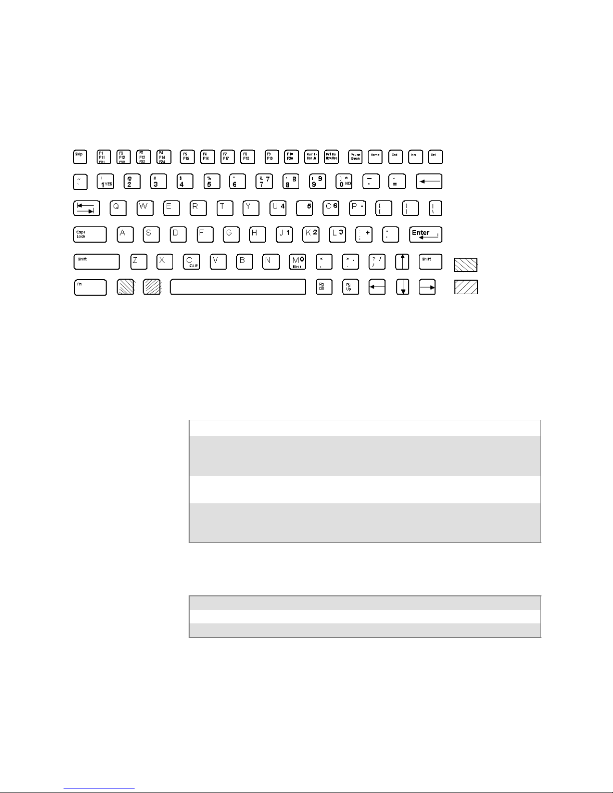
This illustration shows the keyboard for the 5055 Data Collection PC.
Characters on the Keyboard
The special characters and functions printed on the overlay are color-coded
to correspond with the matching shift keys. The shift keys are as follows.
[Shift] Press [Shift] plus a letter to type the letter in uppercase.
[Blue] Theblue(Ctrl)keyputsthekeyboardintoblueshiftmode.Press[Blue]
plus a keyboard key to do an operation printed in blue, or to send a control character.
[Gold] The gold (Alt) key puts the keyboard into gold shift mode. Press [Gold]
plus a keyboard key to do an operation printed in gold.
[NumLock] The green (number lock) key puts the keyboard into [NumLock] mode.
Press [NumLock] plus a keyboard key to type a number or character
printed in green.
5055 Tab Keys
To Enter Press the Keys
Back Tab |Í
Forward Tab Î|
24 Native Terminal Emulation Programmer’s Guide
Page 45

5055 Function Keys
Using the Terminal’s Keyboard—Chapter 2
To Enter Press the Keys
Clear [Gold] [C]
F1 [F1]
F2 [F2]
F3 [F3]
F4 [F4]
F5 [F5]
F6 [F6]
F7 [F7]
F8 [F8]
F9 [F9]
F10 [F10]
F11 [Blue] [F1]
F12 [Blue] [F2]
F13 [Blue] [F3]
F14 [Blue] [F4]
F15 [Blue] [F5]
F16 [Blue] [F6]
F17 [Blue] [F7]
F18 [Blue] [F8]
F19 [Blue] [F9]
F20 [Blue] [F10]
F21 [Gold] [F1]
F22 [Gold] [F2]
F23 [Gold] [F3]
F24 [Gold] [F4]
5055 Auto-Login Restart
To Enter Auto-Login Restart, scan the following bar code (also in Appendix A, “Bar Code Scanning”).
Auto-Login Restart
*/EALRS*
*%ALRS*
25Native Terminal Emulation Programmer’sGuide
Page 46

Using the Terminal’s KeyboardChapter —2
59XX Terminal
@FB
#* %
:?=
For help with using the keyboard, refer to the 5900 Series User’s Guide
(P/N 961-047-121).
!FC +FD [FE $ ]
/&;
NOFA
S
K
I
,
P
C
C
L
L
R
R
S
H
I
F
T
F
U
N
C
Unlabeled Key Colors:
Brown
This illustration shows the keyboard for the 59XX Terminal.
Characters on the Keyboard
The special characters and functions printed on the overlay are color-coded
to correspond with the matching shift keys. The shift keys are as follows.
[Shift] Press [Shift] plus a letter to type the letter in uppercase.
[Brown] The brown key puts the keyboard into brown shift mode. Press [Brown] plus
a keyboard key to type a special character or do operations printed in brown.
[Gold] Thegoldkeyputsthekeyboardintogoldshiftmode.
The [Insert], [CLR],and[Shift] keys have their operations printed to the
right of them. Operations printed to the right are the unshifted values.
Operations printed above the keys are the shifted values.
Gold
26 Native Terminal Emulation Programmer’s Guide
Page 47

59XX Function Keys
Using the Terminal’s Keyboard—Chapter 2
To Enter Press the Keys
Clear [Gold] [.] (period)
F1 [F1]
F2 [F2]
F3 [F3]
F4 [F4]
F5 [F5]
F6 [F6]
F7 [F7]
F8 [F8]
F9 [Brown] [F1]
F10 [Brown] [F2]
F11 [Brown] [F3]
F12 [Brown] [F4]
F13 [Brown] [F5]
F14 [Brown] [F6]
F15 [Brown] [F7]
F16 [Brown] [F8]
F17 [Gold] [F1]
F18 [Gold] [F2]
F19 [Gold] [F3]
F20 [Gold] [F4]
F21 [Gold] [F5]
F22 [Gold] [F6]
F23 [Gold] [F7]
F24 [Gold] [F8]
59XX Auto-Login Restart
To Enter Auto-Login Restart, scan the following bar code (also in Appendix A, “Bar Code Scanning”).
Auto-Login Restart
*/EALRS*
*%ALRS*
27Native Terminal Emulation Programmer’sGuide
Page 48

Using the Terminal’s KeyboardChapter —2
17XX Terminal
For help with using the keyboard, refer to the RT17XX Radio Data Terminal User’s Guide (P/N: 961-047-068).
57-Key Keyboard
F1
F2 F3 F4
F5
F6 F7 F8
@
]
$
&
/
=
?
!+[
#* %
;’ :
–
37-Key Keyboard
Unlabeled Key Colors:
YES
NO
Black
Gold
NO
Brown
Your 17XX Terminal has either a 57-key (left) or a 37-key (right) keyboard as shown in this illustration.
Characters on the Keyboards
The special characters and functions printed on the overlay are color-coded
to correspond with the matching shift keys. The shift keys are as follows.
[Shift] Press [Shift] plus a letter to type the letter in uppercase. The [Shift] key is
located near the top of the keyboard.
[Gold] Thegoldkeyputsthekeyboardintogoldshiftmode.Press[Gold] plus a
keyboard key to type a special character or do an operation printed in gold on
the overlay.
[Black] The black key puts the keyboard into black shift mode. Press [Black] plus a
keyboard key to type a special character or do an operation printed in black
on the overlay.
28 Native Terminal Emulation Programmer’s Guide
Page 49

37-Key Keyboard
Using the Terminal’s Keyboard—Chapter 2
The 37-key keyboard has standard numeric keys, an [Enter] key, and
user-defined function keys in its primary plane. It has alphabetic keys and
special characters in its secondary plane.
Because a terminal with a 37-key keyboard does not have alphabetic keys
in its primary plane, follow these procedures when using its firmware and
downloading software to it. The following chart describes how to type
letters on the 37-key keyboard.
S To access password-protected menus, press [Gold], [Black], [F12],
[F11], then type “52401” for the password; or press [Black], [F3],
[Black], then type “52401” for the password.
S To initiate the COLD START? menu option, press [F10] to answer
“yes.”
S To download software, hold down the [F1] key as you power up the
terminal to go into download mode. This is similar to holding down the
[I] key on the standard 57-key keyboard.
29Native Terminal Emulation Programmer’sGuide
Page 50

Using the Terminal’s KeyboardChapter —2
The following chart describes how to type letters on the 37-key keyboard.
To Enter Press the Keys To Enter Press the Keys
a [Black] [F1] A [Shift] [F1]
b [Black] [F2] B [Shift] [F2]
c [Black] [F3] C [Shift] [F3]
d [Black] [F4] D [Shift] [F4]
e [Black] [F5] E [Shift] [F5]
f [Black] [F6] F [Shift] [F6]
g [Black] [F7] G [Shift] [F7]
h [Black] [F8] H [Shift] [F8]
i [Black] [F9] I [Shift] [F9]
j [Black] [F10] J [Shift] [F10]
k [Black] [F11] K [Shift] [F11]
l [Black] [F12] L [Shift] [F12]
m [Black] [SP] M [Shift] [SP]
n [Black] [Í] N [Shift] [Í]
o [Black] [7] O [Shift] [7]
p [Black] [8] P [Shift] [8]
q [Black] [9] Q [Shift] [9]
r [Black] [4] R [Shift] [4]
s [Black] [5] S [Shift] [5]
t [Black] [6] T [Shift] [6]
u [Black] [1] U [Shift] [1]
v [Black] [2] V [Shift] [2]
w [Black] [3] W [Shift] [3]
x [Black] [Return] X [Shift] [Return]
y [Black] [0] Y [Shift] [0]
z [Black] [.] (period) Z [Shift] [.] (period)
17XX Tab Keys
To Enter Press the Keys
Back Tab [A]
Forward Tab ["]
30 Native Terminal Emulation Programmer’s Guide
Page 51

17XX Function Keys
Using the Terminal’s Keyboard—Chapter 2
To Enter Press the Keys (57-Key)
F1 [F1]
F2 [F2]
F3 [F3]
F4 [F4]
F5 [F5]
F6 [F6]
F7 [F7]
F8 [F8]
F9 [Black] [F1]
F10 [Black] [F2]
F11 [Black] [F3]
F12 [Black] [F4]
F13 [Black] [F5]
F14 [Black] [F6]
F15 [Black] [F7]
F16 [Black] [F8]
F17 [Brown] [F1]
F18 [Brown] [F2]
F19 [Brown] [F3]
F20 [Brown] [F4]
F21 [Brown] [F5]
F22 [Brown] [F6]
F23 [Brown] [F7]
F24 [Brown] [F8]
17XX Auto-Login Restart
To Enter Auto-Login Restart, scan the following bar code (also in Appendix A, “Bar Code Scanning”).
Auto-Login Restart
*/EALRS*
*%ALRS*
31Native Terminal Emulation Programmer’sGuide
Page 52

Using the Terminal’s KeyboardChapter —2
11XX Terminal
For help with using the keyboard, see the 1100 Series Data Terminal User’s
Guide (P/N 961-047-069).
ON/OFF
@! + [
AB
$]# *%
FG
/&; , :
KL
?
PQ
CD
HJ
MNO
=
RT
I
-- .
S
E
UV
Z
F7 F8 F9
7
F4 F5 F6
45 6
F1 F2 F3
12 3
NO
Characters on the Keyboard
The special characters and functions printed on the overlay are color-coded
to correspond with the matching shift keys. The shift keys are as follows.
[Shift] Press the brown [Shift] key plus a letter to type the letter in uppercase. The
[Gold] Thegoldkeyputsthekeyboardintogoldshiftmode.Press[Gold] plus a
[Black] The black key puts the keyboard into black shift mode. Press [Black] plus a
WXY
DEL CLR MENU
SP
89
Unlabeled Key Colors:
YESF0
0
Enter
Black
Gold
Brown
[Shift] key is located near the top of the keyboard.
keyboard key to type a special character or do an operation printed in gold on
the overlay.
keyboard key to type a special character or do an operation printed in black
on the overlay. To lock the keyboard into shift mode, press [Black] [Gold].
To unlock the keyboard, press [Black] [Gold] again.
The [Return] key has its operation printed to the left of it. The operation
printed to the left is its unshifted value. The operation printed above
[Return] is the shifted value.
32 Native Terminal Emulation Programmer’s Guide
Page 53

11XX Tab Keys
11XX Function Keys
Using the Terminal’s Keyboard—Chapter 2
To Enter Press the Keys
Back Tab |Í
Forward Tab Î|
To Enter Press the Keys
F0 [Black] [0]
F1 [Black] [1]
F2 [Black] [2]
F3 [Black] [3]
F4 [Black] [4]
F5 [Black] [5]
F6 [Black] [6]
F7 [Black] [7]
F8 [Black] [8]
F9 [Black] [9]
F10 [Brown] [0]
F11 [Brown] [1]
F12 [Brown] [2]
F13 [Brown] [3]
F14 [Brown] [4]
F15 [Brown] [5]
F16 [Brown] [6]
F17 [Brown] [7]
F18 [Brown] [8]
F19 [Brown] [9]
F20 [Brown] [U]
F21 [Brown] [V]
F22 [Brown] [W]
F23 [Brown] [X]
F24 [Brown] [Y]
11XX Auto-Login Restart
To Enter Auto-Login Restart, scan the following bar code (also in Appendix A, “Bar Code Scanning”).
Auto-Login Restart
*/EALRS*
*%ALRS*
33Native Terminal Emulation Programmer’sGuide
Page 54

Using the Terminal’s KeyboardChapter —2
34 Native Terminal Emulation Programmer’s Guide
Page 55

Using the Terminal Emulation
3
This chapter lists ALL TE parameters. If a certain parameter does not apply to your terminal, the parameter will not appear in the TE configuration
menus.
TheCFGLIT.DATfilespecifiesthetextoftheTEconfigurationmenus.
This chapter assumes you are using the default settings in CFGLIT.DAT.
To customize CFGLIT.DAT, see Chapter 4, “Customizing Your Configu-
ration.”
Menus
35Native Terminal Emulation Programmer’sGuide
Page 56

Using the Terminal Emulation MenusChapter —3
Function Keys
Enter Key
These paragraphs describe how to navigate through the TE configuration
menus.
Press the terminal’s [Enter] key to return to a previous TE configuration
menu. Press [Enter] several times to return to the Main Menu from a submenu. This key also accepts the displayed or keyed input.
Terminals Related [Enter] Keys
2415, 2425, 2455, 2475, 248X
2435A
6400 [ENT] keys
5055 <Enter> via external keyboard
59XX [ENTER] key
17XX, 11XX [ENTER] keys
[or\
keys
v
key (57-key keyboard)
e
key (48-key keyboard)
v
key (39-key function numeric keyboard)
Shift Keys
Y (“Yes”) Key
Use shift keys to put the keyboard in the desired shift mode. These shifted
key functions are shown on the keyboard overlays in Chapter 2, “Using the
Terminal’s Keyboard.”
S For 6400, 5055
[Yellow] and [Blue] shift keys are requ ir ed. For the 5055 PC, the
[Yellow] shift key substitutes the <Alt> key and the [Blue] shift key
substitutes the <Ctrl> key on the external keyboard.
S For 17XX, 11XX
[Gold] and [Black] shift keys are required.
Several displays provide a warning that a certain action can cause your terminal to lose data stored in memory. Press the Y (“yes”) key to proceed as
instructed. Press another key to exit the menu without executing your
original choice.
36 Native Terminal Emulation Programmer’s Guide
Page 57

Up and Down Arrows
For 6400, 5055, 11XX, the up and down arrow keys are defined by the
host computer.
For 59XX, the up and down arrow keys can be made to function more efficiently, in many cases, by pressing the FUNC or ALT key, then pressing
the desired arrow key.
Use these keys to:
S Adjust the length and frequency of the audible buzzer, key click, and
error tone.
S Set the display screen size (the number of rows displayed and characters
per row) and contrast.
Number Keys [0] through [9]
Many menus have numbered options. Press the corresponding numeric
key to make a selection.
Once you make a selection and you remain at that menu screen, the option is highlighted, but you can select additional options. To deselect an
enabled option, press the number corresponding to that option.
Using the Terminal Emulation Menus—Chapter 3
Pressing a number may bring up a submenu. Use the submenu to further
modify the choice you made in the parent menu. After the modifications,
you may return to the parent menu to make additional selections. (This
depends on the menu and function.) Also, you may press a numeric key to
exit a menu or cold start the terminal. These situations are covered later in
this chapter.
Various menus require entering a number, but do not necessarily have
simplechoicessuchas1,2,3,4,etc.Instead,youmayhavetoentera
number from a range of numbers, such as 0–32.
These instances are detailed in the text that applies to those menus, or in
the menu displays.
Note: There are situations where pressing [6] causes the terminal to exit
from a submenu or to reboot.
37Native Terminal Emulation Programmer’sGuide
Page 58

Using the Terminal Emulation MenusChapter —3
Display Annunciators
For 6400, 5055, 59XX, 17XX, 11XX, annunciators show the current status
or operation in progress. Some of the more common annunciators are as
follows:
Note: The following symbols appear larger than actual size on your terminal display. All individual letter annunciators are five pixels in height, except T (temperature) and B (bad battery) which are seven pixels.
Display Position 0
Radio (6400, 5055)
The radio is transmitting data to the base station.
Display Position 1
If the radio icon is displayed in position 0, then position 1 shows the status
of the radio transmission (either receiving, sending, communication loss,
or message waiting). If there is no radio icon shown in position 0, then
this position is blank and position 1 shows the active session number 1 or
2.
Message
A message is received and has not been read.
Specific for 6400, 5055, 59XX Terminals
Sending
Radio is sending data to the base station.
Receiving
Radio is receiving data from the base station. This annunciator appears
only when the information is for this particular computer’s address.
Communication Loss
No communication with the host computer has occurred for at least 60
seconds. The radio computer may be out of radio range, the base station
may not have power, or communications from the host computer to the
base station may not be properly set up.
Specific for 17XX, 11XX Terminals
T
Transmitting data
X
The terminal is transmitting data to the host computer.
Receiving data
R
The terminal is receiving data.
X
Communication Loss
C
L
The terminal cannot communicate with the host computer. The terminal
may be out of radio range, the base radio may not have power, or communication from the host to the base may not be properly set up.
38 Native Terminal Emulation Programmer’s Guide
Page 59

A
Using the Terminal Emulation Menus—Chapter 3
Display Position 2
Input Inhibited
X
The keyboard has accepted enough information for the cur r e nt input field.
If the “key ahead” feature is on, the terminal stores the keystrokes made
after “input inhibited” appears. The host may also inhibit (lockout) the
keyboard upon certain errors or when sending additional information to
your computer.
Insert Mode
^
Characters are inserted, not overwritten.
Display Position 3
Y
Alphabet Character Shift Mode (59XX, 17XX, 11XX,
Green for 6400, 5055)
The keyboard is in the alphabet character shift mode — any alphabet
character keystrokes are entered as uppercase characters.
A
Shift Mode (Blue for 6400, 5055; Black for 11XX, 17XX; varies for 59XX)
The keyboard is in a colored shift mode — keystrokes enter the symbol or
perform the function shown on the overlay to the upper left of the key.
"
Shift Mode (Yellow or Gold for 6400, 5055, 11XX, 17XX; varies for 59XX)
The keyboard is in a colored shift mode — keystrokes enter the symbol or
perform the function shown on the overlay to the upper right of the key.
Display Position 4
Alpha Lock (6400)
This symbol is used only for the 6400 Computer 41-key keyboard model.
Battery is charging (17XX, 11XX)
c
The terminal is connected to a charging source. This does not necessarily
mean the terminal is charging since this is dependent on battery state, temperature, and other conditions.
Display Position 5
Error (17XX)
E
The terminal is connected to a charging source, but charging is not possible.
Display Position 6
Bad Battery (17XX)
B
The battery pack you are currently using is bad.
Temperature (17XX)
T
The terminal is currently out of the battery charging temperature range,
which is 5° to 40° C.
Display Positions 1 through 3
S
Laserscannerinuse(17XX, 11XX)
C
Observe caution labels on laser scanners.
A
N
39Native Terminal Emulation Programmer’sGuide
Page 60

/
Using the Terminal Emulation MenusChapter —3
CL
Display Positions 4 and 5
Caps Lock (5055)
If [Caps Lock] is pressed (activated) on the 5055 external keyboard, the
terminal will type all capital letters regardless of how the text is entered.
XX
NL
+
--
YY
Num Lock (5055)
If [Num Lock] is activated on the 5055 external keyboard, the terminal
will enter numbers as pressed via the right-hand pad on the keyboard.
Display Positions 4 through 6
Low battery condition (17XX, 11XX)
A Low Battery indication is ver y important to the operation of the terminal, letting you know that your terminal will stop operating shortly. Your
terminal should continue to operate 30 minutes to 2 hours depending on
how you use it. Data stored in RAM will be saved for approximately 30
days. However, you should avoid testing this limit.
Your terminal will retain its RAM data storage for up to 5 minutes with
the battery pack removed. It is always a good idea to replace the battery
pack with a fresh recharged pack immediately after removing the discharged pack. Without battery power your terminal will not operate, and
your display will be blank.
Display Positions 4 through 8
Current Row/Column Position (59XX)
Shows the current location of the cursor, with “XX” as the row position
and “YY” as the column position. For example, if the cursor is at row 5,
column 12, the annunciators will show “05/12” in positions 4–8.
Display Positions 5 through 8
Battery Pack Gas Gauge Icons (6400)
These battery icons represent the charge level in your main battery pack.
S Four icons (positions 5–8) indicates more than 76% charge level
S Three icons (positions 5, 6, and 7) indicates between 51–75%
S Two icons (positions 5 and 6) indicates between 26–50%
S One icon (position 5) indicates between 21–25%
When the terminal gets below 20%, the icons are replaced by Ls and after
the charge level is less than 10% your terminal emits a series of beeps.
S Four Ls indicates 16–20% char ge level
S Three Ls indicates 11–15%. At the 15% charge level, your terminal
beeps once. The sound duration and frequency are at levels you have set
foryourterminal.
S Two Ls indicates 6–10%. At the 10% and 7% charge levels, your termi-
nal beeps once. The sound duration and frequency are at levels you have
set for your terminal.
S One L indicates 0–5%. At this charge level, your terminal beeps three
times at its current setting level for both duration and frequency.
40 Native Terminal Emulation Programmer’s Guide
Page 61

Note: If you have the beeper turned off, you will not hear any of the low
battery beep warnings.
The battery pack icons on your terminal display reflect the same status as
theLEDsonthebatterypack.However,theremaybeaoneminutedelay
for updating the icons on the display when the battery pack is replaced.
Configuring TE Parameters
This chapter contains the TE configuration menus for the following terminals: 2415, 2425, 2435A, 2455, 2475, 248X, 6400, 5055, 59XX, 17XX,
and 11XX Terminals unless otherwise noted.
Additional information is available for each of the following:
S Trakker Antares (2415, 2425, 2435A, 2455, 2475, 248X) page 100
S 6400 Computer page 100
S 5055 Data Collection PC page 101
Note: Screens are shown with all of the available options.
S If an option is not assigned to a specific terminal, then that option is
available for all of the terminals addressed in this publication.
S If an option is specific towards a terminal, this option does not appear
on the display, or is blank, for all other terminals.
Using the Terminal Emulation Menus—Chapter 3
KeySequencetoOpenMainMenu
To configure TE parameters on your respective terminal, at the initialization screens or anywhere in a TE session, access the Main Menu by pressing the following key sequence:
Terminal Key Sequence
2415
2425
2435A
2455, 2475, 248X
6400 [Gold] [Blue]
5055 [Blue] [M] or [ALT] [M]
59XX [Brown] [Black]
17XX, 11XX [Gold] [Black]
Note: You can also scan this bar code label to access the Main Menu.
TE configuration menus
)!
(55-key keyboard)
(5
(37-key keyboard)
(!
rl
Green
>
(¡
(57-key keyboard/39-key function numeric keyboard)
,Orange>(48-key keyboard)
*/ETECFG*
*%TECFG*
41Native Terminal Emulation Programmer’sGuide
Page 62

Using the Terminal Emulation MenusChapter —3
Opening the Main Menu
The Main Menu is the f irst screen displayed when you open the computer
menus. All other menus are accessed from the Main Menu. At the initialization screens or anywhere in a TE session, press the appropriate keys to
access the Main Menu (defined within each terminal’s specific information).
After the Main Menu appears, enter a number (1–7) to make a selection.
2415, 2425, 2435A, 2455, 2475, 248X Menus
The following menus pertain to the 2415, 2425, 2435A, 2455, 2475, and
248X Terminals.
To return to the Main Menu, press [Enter] several times, then select
6) Exit Menus,toreturntotheoperatingsystem.
Main Menu
1) Set-up Parms
2) LCD Parms
3) Beeper Setup
4) Tests
5) Version Info
6) Exit Menus
7) More
5) Radio Comm is blank for 2415,
2425, 2435A, 2455, 2475, 248X
Terminals without an 802.1x
supplicant radio driver.
Set-up Parms
1) Communication
2) Barcode Parms
3) Protocol Opts
4) Display Opts
5) Radio Comm
6) Cold Start
7) More
Beeper Setup
1)
2) Error Tone
3)
Version Info
Firmware
<TE Program Name>
Version <number>
Date <ddmmyy>
[1] [2]
[4]
[3]
[5] [7]
LCD Parms
1)
2) Screen Size
3) Screen Mode
4) Annunciators
5)
6) Key Uppercase
7) Scroll Window
Tests
1) Peripherals
2)
3)
4)
5) Numbers
6) Timed Numbers
Main Menu 2
1) Keyboard Opts
2) Save Parms
3)
4)
42 Native Terminal Emulation Programmer’s Guide
Page 63

Using the Terminal Emulation Menus—Chapter 3
1) Set-Up Parms (2415, 2425, 2435A, 2455, 2475, 248X)
This is password-protected to prevent unauthorized users fr om changing
parameters. You can customize the parameter’s CONFIG.DAT set up file
to change the password. See Chapter 5, “Customizing Your Configuration.”
Changed parameters apply to the current session. If more than one session
is available, use the 7) More > 2) Save Parms > 4) Session Menu to verify
or change the current session before going to the next session. To open the
1) Set-up Parms menu, press [1], [Enter], then type “cr52401” at the
prompt to access the following menus.
Set-up Parms
1) Communication
2) Barcode Parms
3) Protocol Opts
4) Display Opts
5) Radio Comm
6) Cold Start
7) More
5) Radio Comm is blank for 2415,
2425, 2435A, 2455, 2475, 248X
Terminals without an 802.1x
supplicant radio driver.
2) RTC/WTP
is for 2415, 2425,
2435A, 2455, 2475,
248X with RTC
7) Native is blank
if TCP/IP
3) Security ID is
for Proxim radios
3) COM Select is for
248X
Controller Type
1)
2) RTC/WTP
3)
Protocol Opts
1) Host View Sze
2) Data Stream
3) Extended Cmds
4) 5250
5) 3270
6) VT220
7) Native
Protocol
1) SST
2) SST-Diag Mode
3) Security ID
Set-up Parms
1) Menu Password
2)
3) COM Select
[1]
[3]
[5]
[7]
Barcode Parms
1) Code 39 Encoded
2)
[2]
3) Concatenate
4) RS232 Stream
5) Stream Scan
6) Scan All Flds
Display Opts
1) Backlight
2) Cursor Mode
[4]
3)
[6]
Cold Start
Enter “Y”
To Cold Start
terminal:
43Native Terminal Emulation Programmer’sGuide
Page 64

Using the Terminal Emulation MenusChapter —3
6400, 5055, 59XX, 17XX, 11XX Menus
The following menus pertain to the 6400, 5055, 59XX, 17XX, and 11XX
Terminals.
To return to the Main Menu, press [Enter] several times, then select
6) Exit Menus,toreturntotheoperatingsystem.
Main Menu
1) Set-up Parms
2) LCD Parms
3) Beeper Setup
4) Tests
5) Version Info
6) Exit Menus
7) More
3) Beeper Select
is for 6400, 5055,
17XX, 11XX
MLID Name
and MLID ver
are for 6400,
5055
Set-up Parms
1) Communication
2) Barcode Parms
3) Protocol Opts
4) Display Opts
5) Radio Comm
6) Cold Start
7) More
Beeper Setup
1) Key Click
2) Error Tone
3) Beeper Select
Version Info
Firmware
<TE Program Name>
Version <number>
Date <ddmmyy>
MLID Name ZZZZZZ
MLID ver xx.xx
(mac address)
[1] [2]
[4]
[3]
[5] [7]
LCD Parms
1) LCD Contrast
2) Screen Size
3) Screen Mode
4) Annunciators
5) Backlight
6) Key Uppercase
7) Scroll Window
Tests
1) Peripherals
2) Converters
3) Memory View
4) Packet Driver
5) Numbers
6) Timed Numbers
Main Menu 2
1) Keyboard Opts
2) Save Parms
3) Cloning Opts
4) Session Menu
1) LCD Contrast and
5) Backlight
is for 59XX, 17XX
4) Annunciators
is blank for
17XX, 11XX
2) Converters
is for 59XX
3) Cloning Opts
is for 59XX, 17XX,
11XX
44 Native Terminal Emulation Programmer’s Guide
Page 65

Using the Terminal Emulation Menus—Chapter 3
1) Set-Up Parms (6400, 5055, 59XX, 17XX, 11XX)
This is password-protected to prevent unauthorized users fr om changing
parameters. You can customize the parameter’s CONFIG.DAT set up file
to change the password. See Chapter 4, “Customizing Your Configuration.”
Changed parameters apply to the current session. If more than one session
is available, use the 7) More > 2) Save Parms > 4) Session Menu to verify
or change the current session before going to the next session. To open the
1) Set-up Parms menu, press [1], [Enter], then type “cr52401” at the
prompt to access the following menus.
Set-up Parms
1) Communication
2) Barcode Parms
3) Protocol Opts
4) Display Opts
5) Radio Comm
6) Cold Start
7) More
2) RTC/WTP
is for 6400, 5055,
59XX, 11XX, 17XX,
with RTC
7) Native is blank
if TCP/IP
3) Security ID is
for Proxim radios
2) Print Device is for
6400
3) COM Select is for
5055
Controller Type
1) ITC Server
2) RTC/WTP
3)
Protocol Opts
1) Host View Sze
2) Data Stream
3) Extended Cmds
4) 5250
5) 3270
6) VT220
7) Native
Protocol
1) SST
2) SST-Diag Mode
3) Security ID
Set-up Parms
1) Menu Password
2) Print Device
3) COM Select
[1]
[3]
[5]
[7]
Scanner Type
1) No Scanner
2) Wand
[2]
3) Laser
4) Wand Emulate
5) Auto Detect
Display Opts
1) Backlight
2) Cursor Mode
[4]
3) Remote Disp
Cold Start
[6]
Enter “Y”
To Cold Start
terminal:
2) Wand,
4) Wand Emulate,
and
5) Auto Detect are
for 59XX, 17XX,
11XX
3) Remote Disp
is for 17XX
45Native Terminal Emulation Programmer’sGuide
Page 66

Using the Terminal Emulation MenusChapter —3
1) Set Up Parameters
The following setup parameter information pertains to all terminals unless
otherwise noted.
1) Communication
The communication option for the terminals are broken down as follows:
S 2415, 2425, 2435A, 2455, 2475, 24 8X Terminals with RTC
2) RTC/WTP below.
S 6400, 5055, 59XX, 17XX, 11XX Terminals with RTC
2) RTC/WTP on page 48.
2) RTC/WTP (2415, 2425, 2435A, 2455, 2475, 248X)
Use 2) RTC/WTP to set, view, or change the terminal ID. This number
allows the host computer to identify individual terminals in the radio data
network. Each terminal must have a unique number in the same network.
Use the numeric keys on the terminal keyboard to modify its ID. Enter a
number between 0–126, then press [Enter] to go to the 2) Host/Cntl menus.
The 1) Radio Setup and 2) Host/Cntl menusareshownonthefollowing
pages. Pending on which option you are exercising you will either advance
to the WTP Stack settings or the TCP/IP Stack settings. 1) Radio Setup is
done in the firmware with the RTC stack.
46 Native Terminal Emulation Programmer’s Guide
Page 67

Using the Terminal Emulation Menus—Chapter 3
WTP Stack Options
DONE
ENTER
Controller Type
1)
2) RTC/WTP
3)
[2]
Host/Cntl
1)
2) Host/Cntl
Host/Cntl
1) CNTL A
2) CNTL B
3) CNTL C
Controller (x)
Enter Unit
Number
xxx
[2]
ENTER
ENTER
Controller (x)
(cust emulation)
unit # xxx
Host Name
Enter up to 16 characters/Numbers for a
name.
ENTER
Emulation (x)
Enter Unit
1) Native
2) 3270
3) 5250
4) VT/ANSI
ENTER
Telnet (x)
1) Enabled
2) Disabled
ENTER
47Native Terminal Emulation Programmer’sGuide
Page 68

Using the Terminal Emulation MenusChapter —3
2) RTC/WTP (6400, 5055, 59XX, 17XX, 11XX)
Use 2) RTC/WTP to set, view, or change the terminal ID. This number
allows the host computer to identify individual terminals in the radio data
network. Each terminal must have a unique number in the same network.
The 1) Radio Setup and 2) Host/Cntl menusareshownonthefollowing
pages. Pending on which option you are exercising you will either advance
to the WTP Stack settings or the TCP/IP Stack settings.
WTP Settings
Use the numeric keys on the terminal keyboard or 5055 external keyboard
to modify its ID. Enter a number between 0–126, then press [Enter] to go
to the 2) Host/Cntl menus.
The LAN ID number can be 0–255 depending on the radio being used.
With the RM60/70 radio, the number can be 0–255; with the RM80/90
radio, the range is 0–15. Your terminal only communicates with equipment using the same ID number that you assigned to your LAN.
If you enter a LAN ID number different from what is configured in the
NET.CFG file you get the following message. If this happens, the system
modifies NET.CFG, which is used by WTPPKT.EXE on initializing the
terminal.
LAN ID changed
Need to reboot
to take effect.
48 Native Terminal Emulation Programmer’s Guide
Page 69

Using the Terminal Emulation Menus—Chapter 3
s
WTP Stack Options
Controller Type
1)
2) RTC/WTP
3)
[2]
Host/Cntl
1) Radio Setup
2) Host/Cntl
For 802.11 Radios Only
Radio Setup
Network Name
xxxx
Enter up to 34 characters for a name
Set Mode/Channel
is for RM60
(902 MHz) radios
ENTER
Radio Setup
Radio Config#
ENTER (5055 -- continue to Host/Cntl setups)
Set Mode/Channel
Use Cursor Up
and Down Keys
To Adjust
DS xxxx
channel xx
For Non 802.11 Radios
Radio Setup
LAN
xx
Only if a “radio cfg“ file is present on the terminal.
Set Frequency
Use Cursor Up
and Down Keys
To Adjust
xxxxxxxxx
[1] [2]
Go to Host/Cntl on the
next page
Set Frequency is for
Synthesized UHF radio
ENTER (continue to Host/Cntl setups)
49Native Terminal Emulation Programmer’sGuide
Page 70

Using the Terminal Emulation MenusChapter —3
ENTER
Host/Cntl Settings
ENTER
Host/Cntl
1) CNTL A
2) CNTL B
3) CNTL C
DONE
ENTER
Controller (x)
Enter Unit
Number
xxx
ENTER
Controller (x)
(cust emulation)
unit # xxx
Host Name
Enter up to 16 characters/Numbers for a
name.
ENTER
Emulation (x)
Enter Unit
1) Native
2) 3270
3) 5250
4) VT/ANSI
Telnet (x)
1) Enabled
2) Disabled
ENTER
ENTER
50 Native Terminal Emulation Programmer’s Guide
Page 71

Using the Terminal Emulation Menus—Chapter 3
2) Barcode Parms (2415, 2425, 2435A, 2455, 2475, 248X)
The 2) Barcode Parms (parameters) menus designate whether you are using a bar code scanner and scan options.
Barcode Parms
1) Code 39 Encoded
2)
3) Concatenate
4) RS232 Stream
5) Stream Scan
6) Scan All Flds
1) Code 39 Encoded
By default, 1) Code39 Encoded is disabled. When you enable this option,
the key press sequences for Encoded Code 39 are used. For more information, see Appendix A, “Bar Code Scanning.”
3) Concatenate
Each bar code read is added to the end of the previous bar code read until
the 2415, 2425, 2435A, 2455, 2475, or 248X Ter minal meets a condition
forcing transmission to the host.
When this option is OFF, each bar code read is placed at the beginning of
the current input field. After a bar code is placed in a field, any subsequent
read replaces the first read.
Note: If you access the TE configuration menus when 4) RS232 Stream is
enabled, all RS-232 data received during this time is lost. Only the data
arriving from the COM1 port on the hand-held terminal is received.
4) RS232 Stream
If this option is enabled, the terminal watches the RS-232 port for activity
in which the terminal reads in the RS-232 data and sends it to the host.
This enables support for fixed-station scanners or scales that send only
RS-232 data without having the host send an extended command to enable the RS-232 port. Default for 4) RS232 Stream is disabled.
5) Stream Scan
If the scanned bar code is too big for the input field, the overflow information appears in the next field and continues until the entire bar code is entered. When this option is OFF, and the scanned bar code is too big for
the input field, the overflow information is dropped.
6) Scan All Flds (Fields)
When this option is selected, the scanner is enabled when the cursor is in
an input field. When this option is OFF, the host computer must enable
the scanner for each input field that requires scanned data.
51Native Terminal Emulation Programmer’sGuide
Page 72

Using the Terminal Emulation MenusChapter —3
2) Barcode Parms (6400, 5055, 59XX, 17XX, 11XX)
Selecting 2) Barcode Parms (parameters) displays the Scanner Type
menu.
ScannerType
UsetheScannerTypemenutodesignatethetypeofbarcodescanner.To
make a selection, press the numeric key corresponding to the desired option, then press [Enter] to access the Scan Options menu.
Note:If1) No Scanner is chosen, the r emaining scanner and bar code op-
tions can be set. Then, if a scanner is used at a later time, only the scanner
type needs to be designated. Selected options are highlighted on the display. Press a key corresponding to that option to deselect a selected option.
Scanner Type
1) No Scanner
2) Wand
3) Laser
4) Wand Emulate
5) Auto Detect
2) Wand,
4) Wand Emulate, and
5) Auto Detect
are for 59XX, 17XX, 11XX
Scan Options
Use the Scan Options menu to assign scan options, enable bar code
symbologies to use (the terminal can only decode the enabled symbologies),
and set options for each enabled bar code symbology, such as the bar code
lengths. Press [Enter] to advance to the Scan Options 2 menus.
Scan Options
1) Redundancy
2) MOD 10 Check
3) Concatenate
4) BC Type Char
5) Stream Scan
6) Scan All Flds
7) More
1) Redundancy (6400, 59XX, 17XX, 11XX)
This option requires two identical scans of a bar code, one right after
another, before the terminal accepts the scan as valid.
2) Mod 10 Check
When you select this option, a check digit is added at the end of the bar
code after a good read for transmission to the host. The host can then validate the transmission data using the check. This feature is not needed with
modem transmission protocols.
1) Redundancy and
4) BC Type Char
are for 6400, 59XX, 17XX, 11XX
3) Concatenate is for 6400, 5055
The bar code number is divided by 10, until the number (or modulus) is
less than 10. If the modulus subtracted from 10 (remainder) is equal to
zero, then the bar code number is valid.
52 Native Terminal Emulation Programmer’s Guide
Page 73

Using the Terminal Emulation Menus—Chapter 3
3) Concatenate (6400, 5055)
Each bar code read is added to the end of the previous bar code read until
the 6400 or 5055 Terminal meets a condition forcing transmission to the
host.
When this option is OFF, each bar code read is placed at the beginning of
the current input field. After a bar code is placed in a field, any subsequent
read replaces the first read.
4) BC Type Char (6400, 59XX, 17XX, 11XX)
This option adds a character associated with the bar code type at the beginning of the scanned bar code. See page 260 for bar code type characters.
5) Stream Scan
If the scanned bar code is too big for the input field, the overflow information appears in the next field and continues until the entire bar code is entered. When this option is OFF, and the scanned bar code is too big for
the input field, the overflow information is dropped.
6) Scan All Flds
When this option is selected, the scanner is enabled when the cursor is in
an input field. When this option is OFF, the host computer must enable
the scanner for each input field that requires scanned data.
7) More
This brings you additional scanning options that adjust scanning timeout
and characters sent before and after the scanned data.
S 1) Scan Timeout (59XX, 17XX, 11XX)
Use this option to adjust the scanning timeout period from 1 to 200
seconds. When using a proximity-detect scanner, you can shorten the
timeout period to speed up scanning while also reducing the duration of
errant scans. With a long-range scanner, you may want to increase the
timeout period to ensure suff icient aiming time.
Scan Timeout
Seconds
XXX
S 2) Scan PreChar and 3) Scan PostChar
Enter a hexadecimal value from 00–FF for the character to be sent preceding the scanned data or after the scanned data. The value of 20h
means that pre- or post-characters are not sent.
Scan Options
1) Scan Timeout
2) Scan PreChar
3) Scan PostChar
1) Scan Timeout is for 59XX, 17XX, 11XX
53Native Terminal Emulation Programmer’sGuide
Page 74

Using the Terminal Emulation MenusChapter —3
Scan Options to Enable Bar Codes
There are menus of options to enable (or disable) various bar code symbologies. To enable a bar code, press the numeric key corresponding to the
number of the bar code symbology (shown on menu), then press [Enter].
After enabling a particular bar code, options may have to be selected for
the bar code. After selecting the desired options, set the length requirements (such as minimum and maximum length, fixed lengths, leading and
trailing character options, etc.).
Once the length requirements are set, the terminal returns to the same
Scan Options menu. Choose another bar code symbology from that menu
or press [Enter] to advance to the Scan Options 2 menu.
Scan Options
1) UPC
2) EAN
3) Code 39
4) Code 128
5) Codabar
4) Sys 1 UPCE is for
6400, 17XX, 11XX
6) Relax Std is for
59XX, 17XX, 11XX
UPC
1) Enabled
2) Add-On 2
3) Add-On 5
4) Sys 1 UPCE
5) Sys 0 UPCE
6) Expand E To A
Code 39
1) Enabled
2) Chk Digit
3) Extended
4) Encoded
5) Auto-Encoded
6) Relax Std
7) Full ASCII
[6]
RELAX CODE 39
1) Quiet zone
2) Data Decode
3) Element Decode
4) START Decode
[1] [2]
[3] [4]
[5]
EAN
1) Enabled
2) Add-On 2
3) Add-On 5
4) Expand 8 To 13
Code 128
1) Enabled
2) UCC/EAN
3) No UCC Type
4) UCC F1 Value
Codabar
1) Codabar
2) ABC Codabar
2) ABC Codabar
is for 59XX, 17XX,
11XX
54 Native Terminal Emulation Programmer’s Guide
Page 75

Using the Terminal Emulation Menus—Chapter 3
Scan Options 2 (Additional Bar Codes)
This menu offers additional bar code selections. After enabling a bar code
symbology, various options, including length can be set.
When all options are set, the display returns to the Scan Options 2 menu.
This menu and the bar code symbologies to be enabled are shown below.
When all needed bar code symbologies are enabled, press [Enter] to return
to the Scan Options menu. Press [Enter] again to back out and return to
the 1) Set-up Parms menu.
Scan Options 2
1) Plessey
2) Str 2of5
3) Int 2of5
5) Code 11 is for
59XX, 17XX, 11XX
4) CI 2of5
5) Code 11
6) Code 93
4) Allow Alpha is for
59XX, 17XX, 11XX
Plessey
1) Enabled
2) MOD10 Chk
3) MOD11 Chk
4) Allow Alpha
Int 2of5
1) Enabled
2) Chk Digit
Code 11
1) Enabled
2) Chk Dig 1
3) Chk Dig 2
[1]
[3] [4]
[5]
[2]
[6]
Str 2of5
1) Enabled
2) Disabled
CI 2of5
1) Enabled
2) Disabled
Code 93
1) Enabled
2) Disabled
55Native Terminal Emulation Programmer’sGuide
Page 76

Using the Terminal Emulation MenusChapter —3
Lengths Options
The Lengths Options menus determine the maximum and minimum
length for a specific bar code symbology. Setting the length of enabled bar
codes helps determine if a scanned bar code is valid and improves response
time. Length options must be set for each enabled bar code.
1 Key in the maximum length (0–99), then press [Enter].
2 Key in the minimum length (0–99), then press [Enter].
3 Fixed-length entries override the maximum and minimum length
entries (minimum and maximum are used for chosen codes). If fixed
lengths are not needed for the enabled bar code, enter zero (0).
Enter the fixed length (0–99), then press [Enter].Uptofourprompts
to set another fixed length will appear. Enter zero (0) for the unused
fixed lengths. Note that Int 2of5 only supports fixed lengths 1 and 2. En-
tries in 3 and 4 are ignored.
4 Enter the number of characters (0–15) to drop from the front (leading)
edge of the scanned bar code, then press [Enter].
5 Enter the number of characters (0–15) to drop from the rear (trailing)
edge of the scanned bar code, then press [Enter].
56 Native Terminal Emulation Programmer’s Guide
Page 77

Using the Terminal Emulation Menus—Chapter 3
After all of the length options are set for the enabled bar code, the display
returns to either the Scan Options menu or the Scan Options 2 menu
(pending on from which menu the bar code was enabled).
(bar code type)
Max Length xx
(bar code type)
Max Length xx
Min Length xx
(bar code type)
Max Length xx
Min Length xx
Fix Length 1 xx
(bar code type)
Max Length xx
Min Length xx
Fix Length 1 xx
Fix Length 2 xx
(bar code type)
Max Length xx
Min Length xx
Fix Length 1 xx
Fix Length 2 xx
Fix Length 3 xx
(bar code type)
Max Length xx
Min Length xx
Fix Length 1 xx
Fix Length 2 xx
Fix Length 3 xx
Fix Length 4 xx
(bar code type)
Drop Leading xx
(bar code type)
Drop Leading xx
Drop Trailing xx
3) Protocol Opts
Use the 3) Protocol Opts menu to designate the type of terminal emulation the host supports. You can also use it to designate additional commands and command sets.
1) Host View Sze
2) Data Stream
3) Extended Cmds
4) 5250
5) 3270
6) VT/ANSI
7) Native
Protocol Opts
7) Native is blank if TCP/IP
57Native Terminal Emulation Programmer’sGuide
Page 78

Using the Terminal Emulation MenusChapter —3
1) Host View Sze
The 1) Host View Sze option tells the terminal the format of display information sent from the host. The display viewing size equals 1920 (the
number of rows times the number of columns). The exception is with
5250 Terminal Emulation which has an additional row for error messages
and therefore has 2000 characters.
The default setting for Native Terminal Emulation is 120 columns by 16
rows (equals 1920). The default for VT/ANSI Terminal Emulation is 80
columns by 24 rows (equals 1920). The default for 5250 Terminal Emulation is 80 columns by 24 rows (25 with error messages).
The default for 3270 Terminal Emulation depends on what the original
setting was before changing to the 3270 Terminal Emulation. Remember
that the total characters must equal 1920 (number of rows by the number
of columns) unless using 5250 Terminal Emulation with error messages.
Enter a number between 1–80 to change the w idth. Press [En ter] to return
to the 3) Protocol Opts menu. “xx ” is the width.
Host View Sze
Width
xx
2) Data Stream
Enter the number corresponding to the type of host computer to specify
the data stream used. Press [Enter] to return to the 3) Protocol Opts
menu.
Data Stream
1) Native
2) 3270
3) 5250
4) VT/ANSI
Note: For 2415, 2425, 2435A, 2455, 2475, and 248X Terminals, you can
also set the emulation type through the 1) ITC Server option.
1) Native is blank if TCP/IP
58 Native Terminal Emulation Programmer’s Guide
Page 79

Using the Terminal Emulation Menus—Chapter 3
For information about 3270, 5250, or VT/ANSI TE, see the following
manuals:
S TE 2000 3270 Terminal Emulation Programmer’s Guide
(P/N: 977-055-003)
S TE 2000 5250 Terminal Emulation Programmer’s Guide
(P/N 977-055-004)
S TE 2000 VT/ ANSI Terminal Emulation Programmer’s Guide
(P/N 977-055-005)
3) Extended Cmds (Commands)
Use 3) Extended Cmds to enable or disable extended commands. By default, extended commands are disabled. When this option is enabled,the
host computer can change or use RS-232 communications (such as printers), bar code options, display screen and font size, and error tone features
of the unit. Press [1] to enable or press [2] to disable the extended command list. Press [Enter] to return to the 3) Protocol Opts menu.
Extended Cmds 1)
Enabled
2) Disabled
4) 5250 (Options)
The 4) 5250 menu enables the following features if the 5250 communication protocol is used. Press the appropriate number to enable an option,
then press [Enter] to return to the 3) Protocol Opts menu.
1) Beep On Error
Causes the buzzer to emit when an error condition occurs; does not lock
up the keyboard.
2) Auto Tab Scan
Causes the cursor to automatically tab forward to the next input field
when a good scan is obtained.
3) Telnet
Handles the Telnet option negotiations to establish a session with an appropriate Telnet server.
Note: 3) Telnet is not changeable if TCP/IP is used.
59Native Terminal Emulation Programmer’sGuide
Page 80

Using the Terminal Emulation MenusChapter —3
4) Device Name
Enters a physical name for the device. This name is 1–10 characters with
allowable values of A–Z, a–z, 0–9, and #, $, -, and @. 5250E R FC 1572
Support.
Note: The first character of 4) Device Name cannot start with a number
(0–9).
The following screen displays after a physical name is entered.
S 1) 5250 Allow Alias
If this is enabled, and your current device name returns an error in use,
then the terminal attempts to append a “$” (dollar sign) to the end of
your device name to initiate a session to your host. When disabled, the
device name is resent to the host for the host to send a FIN packet to
the terminal, causing the terminal to reboot. This continues until the
device name is no longer in use.
Allow Alias
1) 5250 Allow Alias
5) Allow NAWS (Negotiate About Window Size)
When enabled, the terminal will support Telnet option 31 if prompted.
When disabled, this option will return a “won’t do” message.
6) Skip FldExit
When this option is enabled, a field that would generate an error code of
“0020” (field ex it required) when [Enter] was pressed will now send the
field data.
The legacy TE application would send the entire field so a “7” entered into
a 3-character blank-filled field would transmit as “7bb”, a “12” wou ld
transmit as “12b”. The TE 2000 application strips the field fill char acters
so “7” will transmit as a “7”, “12” will transmit as a “12” and so forth.
Note A“b
”indicatesaone-bytespace.
7) More
Select 7) More to modify the function of the period or backspace key.
S 1) Period-Comma (2415, 2425, 2435A, 2455, 2475, 248X)
Select 1) Period-Comma to change the period key ( . ) into a comma.
S 2) Destructive BS (backspace)
Press [2] to use the backspace key to remove (delete) any previouslykeyed data characters. When disabled, the backspace key goes back one
character, but does not delete that character.
60 Native Terminal Emulation Programmer’s Guide
Page 81

Using the Terminal Emulation Menus—Chapter 3
S 3) Lock Error Msg
The TE 2000 cursor modes ensure that the cursor location of the screen
and its su rrounding data is visible. The 5250 error message line is typically not visible because the error message line 24 is too far away from
the cursor location. Enabling this option causes a 5250 Write Error
Code command error message to be visible by placing the cursor on the
error message line. When the RESET key is pressed, the cursor is restored to where it would have been if this option was not enabled (the
location specified by a 5250 Insert Cursor command) and the cursor
mode option then causes that area of the screen to be visible.
Disabling this option causes normal behaviour for the 5250 Write Error
Code command error message. The Write Error Code command error
message is displayed on the error message line of the screen and the cursor is placed at the location specified by the host Insert Cursor command. The cursor mode then causes the cursor area of the screen to be
visible.
5250
1) Beep On Error
2) Auto Tab Scan
3) Telnet
4) Device Name
5) Allow NAWS
6) Skip FldExit
7) More
[7]
5250
1) Period-Comma
2) Destructive BS
3) Lock Error Msg
1) Period-Comma is for
2415, 2425, 2435A, 2455,
2475, 248X
5) 3270 (Options)
The 5) 3270 menu enables the following features if the 3270 communication protocol is used. Press the appropriate number to enable an option,
then press [Enter] to return to the 3) Protocol Opts menu.
1) Keybrd Unlock
Unlocks the keyboard after the [PA1], [PA2],or[C LEAR] keys are
pressed. (Normally the keyboard remains locked, until unlocked or the
terminal is reset by the host, after any of these keys are pressed.) When
using Token Ring on your host, the tab key also unlocks the keyboard.
2) Auto Tab Scan
Causes the cursor to tab forward to the next input field when a good scan
is obtained.
Note: 2) Auto Tab Scan cannotbeenabledatthesametimeas3) Auto
Entr Scan.
61Native Terminal Emulation Programmer’sGuide
Page 82

Using the Terminal Emulation MenusChapter —3
3) Auto Entr Scan
Actuates the <Enter> function when a good scan is obtained.
Note: 3) Auto Entr Scan cannotbeenabledatthesametimeas2) Auto
Tab Scan.
4) Emulate 3210 (6400, 5055, 59XX, 17XX, 11XX)
The IntermecR3210 emulation option allows the 3270 keyboard to emulate an RT3210 Hand-Held Computer, performing the same functions.
For full 3210 compatibility, disable buffering the keyboard, set cur sor to
lazy mode, and set the LCD Parms to Key Uppercase.
5) Telnet
Handles Telnet option negotiations to establish a session with an appropriate Telnet server.
Note: 5) Telnet cannot be changed if you are using TCP/IP.
6) Origin Set
When enabled, this option resets the screen origin when an exclamation
mark is found in the data stream.
7) More
Select 7) More for additional features.
S 1) Device Name
Enters a physical name for the device. This name is 1–10 characters
with allowable values of A–Z, a–z, 0–9, and #, $, -, and @. 3270E RFC
2355 Support.
Note: The first character of 1) Device Name cannot start with a number (0–9).
S 2) Allow NAWS (Negotiate About Window Size)
When enabled, the terminal will support Telnet option 31 if prompted.
When disabled, this option will return a “won’t do” message.
S 3) BRT Auto Enter
When enabled, if the last field on a screen has the reverse video attribute
set, then when that field is exactly filled, the terminal will automatically
send the data for this screen back to the host with an “Enter AID” code.
If disabled, the screen will wait for the user to hit the AID key prior to
sending data back to the host. Default is disabled.
62 Native Terminal Emulation Programmer’s Guide
Page 83

Using the Terminal Emulation Menus—Chapter 3
S 4) Any Auto Enter
When enabled, an automatic “enter” occurs when a reverse video attribute field is filled by keying or scanning data. Any extra scanned data is
discarded. If disabled, the screen waits for the user to hit the AID key
prior to sending data back to the host. Default is d isabled.
3270
1) Keybrd Unlock
2) Auto Tab Scan
3) Auto Entr Scn
4) Emulate 3210
5) Telnet
6) Origin Set
7) More
[7]
3270
1) Device Name
2) Allow NAWS
3) BRT Auto Enter
4) Any Auto Enter
4) Emulate 3210 is for
6400, 5055, 59XX, 17XX, 11XX
6) VT/ANSI
The 6) VT/ANSI menu enables the following features if the VT/ANSI
communication protocol is used.
VT/ANSI
1) DEL To BS
2) CR To CRLF
3) Auto Entr Scn
4) Auto Tab Scan
5) Local Echo
6) AnswerBack
7) More
1) DEL to BS (Delete to Backspace)
Causes the [CLEAR] key to delete the character to the left of the cursor
position, and moves the cursor back one space. When this option is not
enabled, the [CLEAR] key deletes the character at the cursors position.
Default is disabled.
2) CR to CRLF (Carriage Return to Carriage Return/Line Feed)
Causes <Enter> to perform a carriage return and a line feed. When this
option is not enabled, <Enter> performs a carriage return only. Default is
disabled.
3) Auto Entr Scn
Actuates the <Enter> function whenever a good scan is obtained. Default is
enabled for version 6.60 or greater, otherwise the default is disabled.
Note: 3) Auto Entr Scn cannotbeenabledatthesametimeas4) Auto
Tab Scan.
63Native Terminal Emulation Programmer’sGuide
Page 84

Using the Terminal Emulation MenusChapter —3
4) Auto Tab Scan
Causes the terminal to automatically tab to the next input field when a
good scan is obtained. Default is disabled.
Note: 4) Auto Tab Scan cannotbeenabledatthesametimeas3) Auto
Entr Scan.
5) Local Echo
Allows characters to be displayed from terminal memory but not from host
memory. Default is disabled.
6) AnswerBack
Enables you to enter a character string that is sent to the host in response
to an inquiry (hexadecimal 05). The range is 0–30. Default is null string for
2415, 24 25, 2435A, 2455, 2475, 248X, 6400, 5055, 59XX, 17XX, 11XX
Terminals.
AnswerBack
Message
If you enter any of the following control characters, it is sent out. Note that
control strings count as one character.
<ACK> <DC2> <EOT> <GS> <SI> <US>
<BEL> <DC3> <ESC> <HT> <SO> <VT>
<BS> <DC4> <ETB> <LF> <SOH>
<CAN> <DLE> <ETC> <NAK> <STX>
<CR> <EM> <FF> <NUL> <SUB>
<DC1> <ENQ> <FS> <RS> <SYN>
7) More
Calls up the following VT/ANSI More Options screen.
VT/ANSI More Options
1) Screen Lock
2) DiscreteBells
3) UserKey Locked
4) RS232 Setup
5) VT220 Mode
6) Lock Mode
7) More
2) DiscreteBells and
4) RS232 Setup
are for 6400, 5055, 59XX, 17XX,
11XX
S 1) Screen Lock
Sets and locks the screen to a specified size. Any characters outside this
screen size are ignored by the hand-held unit. Default is disabled.
S 2) DiscreteBells (6400, 5055, 59XX, 17XX, 11XX)
If enabled, the terminal beeps f or each bell character the host sends. If
disabled, the unit ignores the bell characters if it is already beeping. De-
fault is disabled.
64 Native Terminal Emulation Programmer’s Guide
Page 85

Using the Terminal Emulation Menus—Chapter 3
S 3) UserKey Locked
If set, the host ignores a host command defining the Function keys. Default is disabled.
S 4) RS232 Setup (64 00, 5055, 59XX, 17XX, 11XX)
When using the media copy command, use this option to set up the
communications port, then press [Enter] to return to 3) Protocol Opts.
S 1) RS232 Baud Rate
Select 1200, 2400, 4800, 9600, 19200, or 38400. Default is 9600.
S 2) RS232 Parity
Select from Odd, Even, or None. Default is None.
S 3) RS232 Stop Bits
Select either 1- or 2-bits. Default is 1.
S 4) RS232 Data Bits
Select either 7- or 8-bit. Default is 8.
S 5) RS232 Flow
SelectfromNone,DTR,orXON/XOFF.Default is None.
RS232 Baud Rate
1) 1200
2) 2400
3) 4800
4) 9600
5) 19200
6) 38400
7)
8)
RS232 Stop Bits
1) 1
2) 2
RS232 Setup
1) RS232 Baud Rate
2) RS232 Parity
3) RS232 Stop Bits
4) RS232 Data Bits
5) RS232 Flow
[1]
[3] [4]
[2]
RS232 Parity
1) Odd
2) Even
3) None
RS232 Data Bits
1) 7
2) 8
RS232 Flow
1) None
2) DTR
3) XON/XOFF
[5]
65Native Terminal Emulation Programmer’sGuide
Page 86

Using the Terminal Emulation MenusChapter —3
S 5) VT220 Mode
Selects operating in character or block mode. Select a choice, then press
[Enter] to return to the 3) Protocol Opts menu. Default is 1) Char.
S 1) Char (Default)
Sets the mode to Character mode. The terminal sends each character
as it is pressed.
S 2) Block
SetsthemodetoLineEdit(block)mode.Theterminalsendsablock
of characters when a terminating key is pressed.
S 3) Transmit BS
When enabled, pressing the backspace key sends a backspace to the
host for the host to echo back to the terminal. When disabled, the
backspace key is handled locally on the terminal by doing a destructive backspace to the printed data characters on the display.
VT220 Mode
1) Char
2) Block
3) Transmit BS
S 6) Lock Mode
Use the Mode key on the terminal’s keyboard or keypad to toggle between Line Edit (block) mode and Character mode. Use the Lock Mode
option to disable the Mode key in the VT/ANSI data stream. By default,
Lock mode is disabled.
S 7) More
Selects the telnet option for the VT/ANSI data stream.
VT/ANSI
1) Telnet
2) Term Setup
3) Send XON
4) Keypad Mode
5) VT Cursor Mode
6) Terminal Mode
7) More
S 1) Telnet
Handles telnet option negotiations to establish a session with an appropriate telnet server. This cannot be changed if using TCP/IP.
66 Native Terminal Emulation Programmer’s Guide
Page 87

Using the Terminal Emulation Menus—Chapter 3
S 2) Term Setup
Selects the compliance level of the terminal being emulated. Default is
VT340 to support all commands. Make a selection, then press [Enter]
to return to the 3) Protocol Opts menu.
Term Setup
1) ANSI
2) VT100
3) VT220
4) VT320
5) VT340
6) IBM 330X
S 3) Send XON
Default is enabled which indicates that when an RIS is received from
the host, the XON character is returned after compliance of this
command. Default is enabled.
S 4) Keypad Mode
Determines what is returned to the host when keys are pressed. Default is 2) Numeric.
S 1) Application
Generates application ESC sequences for the key code. For help,
refertoyourVTmanual.
S 2) Numeric
Generates ANSI cursor control ESC sequences that correspond to
what appears on the face of the keys.
Keypad Mode
1) Application
2) Numeric
67Native Terminal Emulation Programmer’sGuide
Page 88

Using the Terminal Emulation MenusChapter —3
S 5) VT Cursor Mode
Determines what is returned to the host when cursor keys are hit.
Default is 2) Cursor.
S 1) Application
Generates application ESC sequences for the key code. For help,
refertoyourVTmanual.
S 2) Cursor
Generates ANSI cursor control ESC sequences that correspond to
what appears on the face of the cursor key.
VT Cursor Mode
1) Application
2) Cursor
S 6) Terminal Mode (VT220/320 only)
Sets the terminal mode to 7-bit or 8-bit. This option sets the mode
VT-series terminals used to exchange escape sequences, control commands, and status reports with an application. Default is 1) 7-Bit.
Terminal Mode
1) 7-Bit
2) 8-Bit
S 7) More
Below are additional options:
VT/ANSI
1) Use PC Char Set
2) Allow NAWS
3) Terminal ID
4) Auto Wrap
S 1) Use PC Char Set
S 2) Allow NAWS (Negotiate About Window Size)
68 Native Terminal Emulation Programmer’s Guide
Select this option to default the font character to the terminal’s character set instead of a DEC terminal character set.
When enabled, the terminal supports Telnet option 31 if prompted.
When disabled, this option returns a “won’t do” message.
Page 89

Using the Terminal Emulation Menus—Chapter 3
S 3) Terminal ID
This enables the entry of a character string sent back to the host in
response to IAC SB terminal type SE. The range is 0 through 30,
with null string as the default. If set to null, then ANSI, VT100,
VT220, VT320, or VT340 is returned as selected.
Terminal ID
Terminal Type
S 4) Auto Wrap
If enabled, graphic display characters received when the cursor is at
the right margin appear on the next line. The screen scrolls up if the
cursor is at the end of the scrolling region.
If disabled (default), graphic characters received when the cursor is at
the right margin replace previously displayed characters.
69Native Terminal Emulation Programmer’sGuide
Page 90

Using the Terminal Emulation MenusChapter —3
Note: 7) Native is enabled by default to preserve backwards compatibility.
7) Native (2415, 2425, 2435A, 2455, 2475, 248X, 6400, and 5055 with WTP,
59XX, 17XX, 11XX)
S For 2415, 2425, 2435A, 2455, 2475, 248X Terminals with WTP:
When enabled, pressing [F1] is equivalent to pressing [FnL] [7]
(Home), while pressing [F2] is equivalent to pressing [F1],etc.When
disabled, [F1] is equivalent to [F1], [F2] is equivalent to [F2],etc.
S For 2435A Terminals with 48-key keyboards:
When enabled, pressing [F1] is equivalent to pressing Green>,
H
.(Home), while pressing [F2] is equivalent to pressing Orange>,
1
,etc.Whendisabled,[F1] is equivalent to pressing Orange>,
[F2] is equivalent to pressing Orange>,2,etc.
S For 6400 Computers with WTP on a 51-key keyboard:
When enabled, pressing [F1] is equivalent to pressing [Blue] [0],while
pressing [F2] is equivalent to pressing [Blue] [1 ],etc.Whendisabled,
[F1] is equivalent to [Blue] [1], [F2] is equivalent to [Blue] [2],etc.
S For 6400 Computers with WTP on a 41-key keyboard:
When enabled, pressing [F1] is equivalent to pressing [Blue] [Space].
1
,
S For 5055 Terminals with WTP:
When enabled, pressing [F1] is equivalent to pressing [Blue] [0],while
pressing [F2] is equivalent to pressing [Blue] [1 ],etc.Whendisabled,
[F1] is equivalent to [Blue] [1], [F2] is equivalent to [Blue] [2],etc.
S For 59XX, 17XX, 11XX,
When enabled, pressing [F1] is equal to [Black] [0] and [F2] is equal to
[Black] [1],etc.Whendisabled,[F1] is equal to [Black] [1], [F2] is
equal to [Black] [2],etc.
Native Mode
1) F1 is FUNC-0
70 Native Terminal Emulation Programmer’s Guide
Page 91

Using the Terminal Emulation Menus—Chapter 3
4) Display Opts
4) Display Opts adjusts the backlight timer, the cursor appearance on the
display, or the remote display.
Display Opts
1) Backlight
2) Cursor Mode
3) Remote Disp
1) Backlight is for 2415, 2425, 2435A, 2455,
2475, 248X, 6400, 17XX, 11XX
3) Remote Disp is for 17XX
1) Backlight (2415, 2425, 2435A, 2455, 2475, 248X, 6400, 17XX, 11XX)
Use the up and down arrows to select “Off” or a number from “1–60” for
2415, 2425, 2435A, 2455, 2475, and 248X Terminals or from “1–255”
for 6400, 17XX, and 11XX Terminals. This would dictate the number of
seconds that the backlight stays on after a key is pressed.
Backlight Timer
Use Cursor Up
And Down Keys
To Adjust
xxx
2) Cursor Mode
Selects the cursor style. After making a selection, press [Enter] to return to
the 4) Display Opts menu. The cursor shape is shown between “>” and
“<”.
1) Underline Blink
Causes the underline character to appear and disappear in its current location.
2) Block Blink
Causes the block (J) character cursor to appear and disappear in its current location.
3) Underline (6400, 59XX, 17XX, 11XX)
This option provides a solid underline character to display the cursor’s current location.
71Native Terminal Emulation Programmer’sGuide
Page 92

Using the Terminal Emulation MenusChapter —3
4) Block (6400, 59XX, 17XX, 11XX)
This provides a reverse or highlighted block (J)characterdisplayingthe
cursor’s current location.
Cursor Mode
1) Underline Blink
2) Block Blink
3) Underline
4) Block
><
3) Underline and
4) Block
are for 6400, 59XX, 17XX,
11XX
3) Remote Disp (17XX)
This menu allows communication to a remote display.
1) Enabled
Pressthisoptiontoenabletheremotedisplayfunction.
2) Screen Size
Usethisoptiontosetthescreensizeoftheremotedisplay.
3) Remote Baud
Select the appropriate baud rate for the remote display: 9600, 19200, or
38400.
4) Remote Type
Use this option to identify the remote ter minal: VT100, VT220, or ANSI.
Remote Display
1) Enabled
2) Screen Size
3) Remote Baud
4) Remote Type
72 Native Terminal Emulation Programmer’s Guide
Page 93

Using the Terminal Emulation Menus—Chapter 3
5) Radio Comm (Blank for 2415, 2425, 2435A, 2455, 2475, 248X Terminals
without an 802.1x Supplicant Radio Driver)
Note: Diagnostic modes disable data compression and are reserved for
engineering tests.
Menus for 5) Radio Comm specify the communication protocol and
speed in certain instances. Depending on circumstances, one of the two
menus will appear.
For 2415, 2425, 2435A, 2455, 2475, 248X Terminals with an 802.1x
Supplicant Radio Driver
The following menu appears:
Radio Comm
1) User Auth
1) User Auth
When enabled, the terminal prompts for a user name and password before
sending any radio data. When disabled, the terminal will use the machine
authentication as set up in the firmware menus.
For 6400, 5055, 59XX, 17XX, 11XX Terminals
This menu enables or disables the SST diagnostic mode.
Protocol
1) SST
2) SST-Diag Mode
3) Security ID
3) Security ID (Proxim radios)
This changes the radio security identification. Enter the new security ID
(up to 16 characters) twice. If the old security ID is not correct or if the
second new security ID was not entered correctly, you will see the “unchanged” message on the bottom line of the display (note the left screen).If
the new security ID is entered correctly, the following screen on the right
will appear.
3) Security ID is for Proxim radios
Protocol
Security ID
New Security ID
New Security ID
Protocol
Security ID changed.
Save parms then reboot terminal for
change to take affect.
73Native Terminal Emulation Programmer’sGuide
Page 94

Using the Terminal Emulation MenusChapter —3
6) Cold Start
This resets all TE values to the stored configuration in CONFIG.DAT
and performs a cold-start on the terminal. Press [Y] to reboot the terminal,
or press any other key to return to the 1) Set-up Parms menu.
Depending on the setting in the firmware menu of the terminal, after rebooting, the terminal opens to the TRAKKER Antares 2400 Menu System.
Cold Start Enter
‘Y’
to Cold Start
terminal:
7) More
7) More provides the following additional setup parameters:
Set-UP Parms
1) Menu Password
2) Print Device
3) COM Select
2) Print Device is for 6400
3) COM Select is for 248X, 5055
1) Menu Password
This parameter enables menu password protection for the TE configuration menus. This provides added protection because once enabled, the
password must be entered before any further activity can occur within the
terminal emulation menu screens. The default is to have this option disabled.
To enable the password, press [1], then type “3193693” for the fixed password set by Intermec Technologies Corporation. The“1)”willchangeto
reverse video to indicate it is enabled. With this enabled, enter this password
when you access the terminal emulation menu screens. Press [Enter] until
you reach the Main Menu,thenpress6) Exit Menus to return to the
main terminal screen.
To disable the password, press [1] to display in normal viewing text. You
do not need to enter a password to disable this function. Note that the
menu password can be set via a custom configuration. See Chapter 4, “Customizing Your Configuration,” for help on creating a custom configuration file.
74 Native Terminal Emulation Programmer’s Guide
Page 95

Using the Terminal Emulation Menus—Chapter 3
2) Print Device (6400)
Establishes extended commands f or the RS-232, IrDA, or RF printer drivers. Press [1] for the RS-232 driver (default) or [2] for the IrDA driver.
Print Device
1) RS232 Print
2) IRDA Print
3)
4)
3) COM Select (248X, 5055)
Selects which communications port to use for extended commands,
RS-232 communications, or media copy commands.
COM Select
1) COM 1
2) COM 2
2) LCD Parms (Parameters)
2) LCD Parms adjusts these Liquid Crystal Display (LCD) features: the
screen size (number of rows displayed, and the number of characters displayed on each row), the screen mode (how the cursor positions itself on
the display), making all alphabetic character keystrokes uppercase characters, and scrolling window parameters.
1) LCD Contrast
2) Screen Size
3) Screen Mode
4) Annunciators
5) Backlight
6) Key Uppercase
7) Scroll Window
1) LCD Contrast (59XX, 17XX)
Usethisoptiontoadjustthecontrastofthedisplaytoamorereadablelevel (range 0–255). The terminal uses this setting as a baseline, automatically
readjusting contrast as necessary, based on temperature changes. Use the
up and down arrow keys to adjust the contrast, then press [Enter] to return to the LCD Parms screen.
LCD Parms
LCD Contrast
Use Cursor Up
and Down Keys
To Adjust
xxx
1) LCD Contrast is for 59XX, 17XX
2) Screen Size is blank for 2480, 2485
4) Annunciators is blank for 17XX
5) Backlight is for 59XX, 17XX
75Native Terminal Emulation Programmer’sGuide
Page 96

Using the Terminal Emulation MenusChapter —3
Note: 2) Screen Size is available for 2415, 2425, 2435A, 2455, 2475,
2481, and 2486 Terminals on firmware 7.00 or greater and with DoubleByte Country Code equal to 00 (USA).
2) Screen Size (blank for 2480, 2485)
2) Screen Size selects the number of lines and characters in each line to be
viewed on the display. To change the screen size:
1 Press the arrow keys. Each key press moves the word On one position in
the direction of the arrow key pressed. The word On indicates the current setting.
2 When the word On appears in the position corresponding to the desired
screen size, press [Enter].
2415 and 2425 Terminal Screen Sizes
Choices for the 2415 and 2425 Terminals include the following. Only one
option can be selected at a time. (Default is 16 x 20)
S 4 rows, with 10, 12, 17, 22, or 26 characters per row
S 6 rows, with 10, 12, 17, 22, or 26 characters per row
S 8 rows, with 10, 12, 17, 20, 22, or 26 characters per row
S 10 rows, with 12, 17, 22, or 26 characters per row
S 12 rows, with 12, 17, 22, or 26 characters per row
S 16 rows, with 12, 17, 20, 22, 26, or 32 characters per row
S 21 rows, with 12, 17, 22, 26, or 32 characters per row
Screen Size
10 12 17 20 22 26 32
4 Off Off Off Off Off
6 Off Off Off Off Off
8 Off Off Off Off Off Off
10 Off Off Off Off
12 Off Off Off Off
16 Off Off On off Off Off
21 off off Off Off Off
76 Native Terminal Emulation Programmer’s Guide
Page 97

Using the Terminal Emulation Menus—Chapter 3
2435A Terminal Screen Sizes
For 2435A Terminals with Terminal Emulation version 6.60 or greater and
firmware version 7.10 or greater, if icons are enabled in the firmware, then
the 2435A Terminal uses the following screen sizes.
Iftheiconsaredisabledinthefirmware(default), then the 2435A Termi-
nal uses the screen sizes as shown on page 76 for the 2415 and 2425 Terminals. Only one option can be selected at a time. (Default is 16 x 19)
S 4 rows, with 9, 12, 17, 22, or 26 characters per row
S 6 rows, with 9, 12, 17, 22, or 26 characters per row
S 8 rows, with 9, 12, 17, 19, 22, or 26 characters per row
S 10 rows, with 12, 17, 22, or 26 characters per row
S 12 rows, with 12, 17, 22, or 26 characters per row
S 16 rows, with 12, 17, 19, 22, 26, or 31 characters per row
S 21 rows, with 12, 17, 22, 26, or 31 characters per row
Screen Size
9 121719222631
4 Off Off Off Off Off
6 Off Off Off Off Off
8 Off Off Off Off Off Off
10 Off Off Off Off
12 Off Off Off Off
16 Off Off On off Off Off
21 off off Off Off Off
77Native Terminal Emulation Programmer’sGuide
Page 98

Using the Terminal Emulation MenusChapter —3
2455 Terminal Screen Sizes
Choices for the 2455 Terminal include the following. Only one option
can be selected at a time. (Default is 25 x 80)
S 8 rows, with 33 or 40 characters per row
S 12 rows, with 40, 53, or 80 char acters per row
S 20 rows, with 80 characters per row
S 25 rows, with 80 characters per row
Screen Size
33 40 53
8
12
20
25
Off Off
Off
Off80Off
Off
On
For 2455 Terminals with Terminal Emulation version 6.73 or greater and
firmware version 7.15.09 or 7.15.77 or greater, the 2455 Terminals use the
following screen sizes. Only one option can be selected at a time. (Default
is 25 x 80)
S 8 rows, with 20, 33, or 40 characters per row
S 12 rows, with 20, 33, 40, 53, or 80 characters per row
S 16 rows, with 20, 33, 40, or 53 characters per row
S 20 rows, with 80 characters per row
S 25 rows, with 80 characters per row
Screen Size
20 33 40 53 80
8 Off Off Off
12 Off Off Off Off Off
16 Off Off Off Off
20 Off
25 On
78 Native Terminal Emulation Programmer’s Guide
Page 99

Using the Terminal Emulation Menus—Chapter 3
2475, 2481, and 2486 Terminal Screen Sizes
Note: This information does not apply to the 2480 and 2485 Terminals.
Choices for the 2475, 2481, and 2486 Terminals include the following.
Only one option can be selected at a time. (Default is 25 x 64)
S 12 rows, with 20, 26, 40, 53, or 64 characters per row
S 20 rows, with 40 characters per row
S 25 rows, with 40, 55, or 64 char acters per row
Screen Size
20 26 40 53 64
12 Off Off Off
20 Off
25 off off On
For 2475, 2481, and 2486 Terminals with Terminal Emulation version
6.73 or greater and firmware version 7.15.09 or 7. 15.77 or greater, the
2475, 2481, and 2486 Terminals use the following screen sizes. Only one
option can be selected at a time. (Default is 25 x 64)
S 12 rows, with 20, 26, or 40 char acters per row
S 16 rows, with 20 or 26 characters per row
S 20 rows, with 40 characters per row
S 25 rows, with 40, 53, or 64 char acters per row
Screen Size
20 26 40 53 64
12 Off Off Off
16 Off Off
20 Off
25 Off Off On
79Native Terminal Emulation Programmer’sGuide
Page 100

Using the Terminal Emulation MenusChapter —3
6400 Computer Screen Sizes
Choices for the 6400 Computer include the following. It is also possible to
have selected 5, 8, 10, and 16 for number of rows. This depends on what
size of display you have selected. Only one option can be selected at a
time. (Default is 18 x 20)
S 6 rows, with 10, 13, 16, 20, 23, 26, or 32 characters per row
S 9 rows, with 10, 13, 16, 20, 23, 26, or 32 characters per row
S 12 rows, with 10, 13, 16, 20, 23, 26, or 32 characters per row
S 18 rows, with 10, 13, 16, 20, 23, 26, or 32 characters per row
Screen Size
10 13 16 20 23* 26 32
6 Off Off Off off Off Off Off
9 Off Off Off Off Off Off Off
12 Off Off Off Off Off Off Off
18 Off Off Off On off Off Off
With 1.23 of BIOS 5.36 of Terminal Emulation
5055 PC Screen Sizes
Choices for the 5055 PC include the following. It is also possible to select
5, 8, 10, and 16 for number of rows. This depends on what size of display
you have selected. Only one option can be selected at a time.
(Default is 25 x 80)
S 8rows,with20columnsperrow
S 10 rows, with 20 columns per row
S 12rows,with20or40columnsperrow
S 16 rows, with 20, 40, or 80 columns per row
S 21rows,with40or80columnsperrow
S 25rows,with40or80columnsperrow
Screen Size
20 40 80
8
10
12
16
21
25
Off
Off
Off Off
Off Off Off
Off Off
Off On
80 Native Terminal Emulation Programmer’s Guide
 Loading...