

Page 1

Installation
Instructions
6820 Printer
Page 2

Intermec Technologies Corporation
World Headquarters
6001 36th Ave. W.
Everett, WA 98203
U.S.A.
www.intermec.com
The information contained herein is provided solely for the purpose of allowing customers to operate
and service Intermec-manufactured equipment and is not to be released, reproduced, or used for any
other purpose without written permission of Intermec Technologies Corporation.
Information and specifications contained in this document are subject to change without prior notice
and do not represent a commitment on the part of Intermec Technologies Corporation.
© 2007 Intermec Technologies Corporation. All rights reserved.
The word Intermec, the Intermec logo, Norand, ArciTech, Beverage Routebook, CrossBar,
dcBrowser, Duratherm, EasyADC, EasyCoder, EasySet, Fingerprint, INCA (under license), i-gistics,
Intellitag, Intellitag Gen2, JANUS, LabelShop, MobileLAN, Picolink, Ready-to-Work, RoutePower,
Sabre, ScanPlus, ShopScan, Smart Mobile Computing, TE 2000, Trakker Antares, and Vista Powered
are either trademarks or registered trademarks of Intermec Technologies Corporation.
There are U.S. and foreign patents as well as U.S. and foreign patent applications pending.
Bluetooth is a trademark of Bluetooth SIG, Inc., U.S.A.
ii 6820 Printer Installation Instructions
Page 3

Contents
Global Services and Support . . . . . . . . . . . . . . . . . . . . . . . . . . . . . . . . . . . . . . . . . . . . . . . . . . . . . . . . . . . . . iv
Warranty Information. . . . . . . . . . . . . . . . . . . . . . . . . . . . . . . . . . . . . . . . . . . . . . . . . . . . . . . . . . . . . . . iv
Web Support. . . . . . . . . . . . . . . . . . . . . . . . . . . . . . . . . . . . . . . . . . . . . . . . . . . . . . . . . . . . . . . . . . . . . . iv
Telephone Support . . . . . . . . . . . . . . . . . . . . . . . . . . . . . . . . . . . . . . . . . . . . . . . . . . . . . . . . . . . . . . . . . iv
Using the Installation Kit. . . . . . . . . . . . . . . . . . . . . . . . . . . . . . . . . . . . . . . . . . . . . . . . . . . . . . . . . . . . . . . . 7
Installation Procedures . . . . . . . . . . . . . . . . . . . . . . . . . . . . . . . . . . . . . . . . . . . . . . . . . . . . . . . . . . . . . . 7
Tools Required . . . . . . . . . . . . . . . . . . . . . . . . . . . . . . . . . . . . . . . . . . . . . . . . . . . . . . . . . . . . . . . . . . . . 7
Installing the Battery Cable . . . . . . . . . . . . . . . . . . . . . . . . . . . . . . . . . . . . . . . . . . . . . . . . . . . . . . . . . . . . . . 7
Installing the Direct-to-Battery Cable . . . . . . . . . . . . . . . . . . . . . . . . . . . . . . . . . . . . . . . . . . . . . . . . . . . 8
Routing Cables . . . . . . . . . . . . . . . . . . . . . . . . . . . . . . . . . . . . . . . . . . . . . . . . . . . . . . . . . . . . . . . . 8
Preparing the Vehicle Battery Cable . . . . . . . . . . . . . . . . . . . . . . . . . . . . . . . . . . . . . . . . . . . . . . . . . 9
Connecting to the Vehicle Battery . . . . . . . . . . . . . . . . . . . . . . . . . . . . . . . . . . . . . . . . . . . . . . . . . 10
Connecting to a Two Battery Vehicle System . . . . . . . . . . . . . . . . . . . . . . . . . . . . . . . . . . . . . . . . . 13
Securing the Vehicle Battery Cable . . . . . . . . . . . . . . . . . . . . . . . . . . . . . . . . . . . . . . . . . . . . . . . . . 13
Grounding the Printer Power Cables . . . . . . . . . . . . . . . . . . . . . . . . . . . . . . . . . . . . . . . . . . . . . . . 14
Verifying the Printer Power Cable Voltage . . . . . . . . . . . . . . . . . . . . . . . . . . . . . . . . . . . . . . . . . . . . . . 15
Installing the Printer . . . . . . . . . . . . . . . . . . . . . . . . . . . . . . . . . . . . . . . . . . . . . . . . . . . . . . . . . . . . . . . . . . 16
Fixed Mount Printer P/N 709-850-006 Mounting Plate (Optional) . . . . . . . . . . . . . . . . . . . . . . . . . . . 16
Wall Mount Printer Kits . . . . . . . . . . . . . . . . . . . . . . . . . . . . . . . . . . . . . . . . . . . . . . . . . . . . . . . . . . . . 19
Contents of Flat Paper Tray - P/N 203-486-00 . . . . . . . . . . . . . . . . . . . . . . . . . . . . . . . . . . . . . . . 19
Contents of Compact Paper Tray - P/N 203-489-001 . . . . . . . . . . . . . . . . . . . . . . . . . . . . . . . . . . 20
Installing the Mounting Plate . . . . . . . . . . . . . . . . . . . . . . . . . . . . . . . . . . . . . . . . . . . . . . . . . . . . . 23
Attaching Either Paper Tray to the Mounting Plate . . . . . . . . . . . . . . . . . . . . . . . . . . . . . . . . . . . . 24
Mounting the Printer . . . . . . . . . . . . . . . . . . . . . . . . . . . . . . . . . . . . . . . . . . . . . . . . . . . . . . . . . . . 25
6820 Printer Installation Instructions iii
Page 4

Global Services and Support
This section provides you with safety information, technical support
information, and sources for additional product information.
Safety Information
Your safety is extremely important. Read and follow all warnings and
cautions in this document before handling and operating Intermec
equipment. You can be seriously injured, and equipment and data can be
damaged if you do not follow the safety warnings and cautions.
This section explains how to identify and understand dangers, warnings,
cautions, and notes that are in this document. You may also see icons that
tell you when to follow ESD procedures and when to take special
precautions for handling optical parts.
A warning alerts you of an operating procedure, practice, condition, or
statement that must be strictly observed to avoid death or serious injury
to the persons working on the equipment.
Global Services and Support
A caution alerts you to an operating procedure, practice, condition, or
statement that must be strictly observed to prevent equipment damage
or destruction, or corruption or loss of data.
Note: Notes either provide extra information about a topic or contain spe-
cial instructions for handling a particular condition or set of circumstances.
Global Services and Support
Warranty Information
To understand the warranty for your Intermec product, visit the Intermec
web site at www.intermec.com and click Service & Support > Warranty.
Web Support
Visit the Intermec web site at www.intermec.com to download our current
documents (in PDF). To order printed versions of the Intermec manuals,
contact your local Intermec representative or distributor.
Visit the Intermec technical knowledge base (Knowledge Central) at
intermec.custhelp.com to review technical information or to request
technical support for your Intermec product.
iv
6820 Printer Installation Instructions
Page 5

Global Services and Support
Telephone Support
These are available from Intermec Technologies Corporation.
Service Description
In the U.S.A. and Canada, call 1-800755-5505 and choose this option
Order Intermec products • Place an order.
• Ask about an existing order.
Order Intermec media Order printer labels and ribbons. 1 and then choose 1
Order spare parts Order spare parts 1 or 2 and then choose 4
Technical Support Talk to technical support about
your Intermec product.
Service • Get a return authorization
number for authorized service
center repair.
• Request an on-site repair
technician.
Service contracts • Ask about an existing contract.
• Renew a contract.
• Inquire about repair billing or
other service invoicing
questions.
1 and then choose 2
2 and then choose 2
2 and then choose 1
1 or 2 and then choose 3
Outside the U.S.A. and Canada, contact your local Intermec representative.
To search for your local representative, from the Intermec web site, click
About Us > Contact.
6820 Printer Installation Instructions v
Page 6

Service Location Support
For the most current listing of service locations, click Support > Returns
and Repairs > Repair Locations.
For technical support in South Korea, use the after service locations listed
below:
AWOO Systems
102-1304 SK Ventium
522 Dangjung-dong
Gunpo-si, Gyeonggi-do Korea, South 435-776
Contact: Mr. Sinbum Kang
Telephone: +82-31-436-1191
Email: sbkang@awoo.co.kr
IN Information System Ptd LTD
6th Floor
Daegu Venture Center Bldg 95,
Shinchum 3 Dong
Donggu, Daegu City, Korea
Email: jmyou@idif.co.kr OR korlim@gw.idif.co.kr
Global Services and Support
vi 6820 Printer Installation Instructions
Page 7

Using the Installation Kit
When the installation is complete, you will have a secure place to store the
printer and hand-held or mobile computer. The vehicle electrical system
provides power to operate the printer, vehicle dock; and charge the printer
internal battery.
In this installation, the power cable is wired directly to the vehicle battery.
This reduces installation problems and the vehicle battery filtering.
The installation kits contain all of the hardware (nuts, bolts, washers, a
terminal ring, and a fuse link) for connecting the battery cable directly to
the vehicle battery. These kits also contain adjustable wire clamps to secure
the cable in place.
Note: These instructions are required to install the following kit numbers:
P/N 203-242-101 (Fixed Mount and Wall Mount Printers)
P/N 203-242-102 (Portable Printers).
The 6820 Printer and associated electrical wiring should be installed under
the supervision of properly trained and qualified personnel. Follow these
installation instructions to ensure safe, reliable performance of the 6820
Printer.
Installation Procedures
There are three steps to install your printer
1 Installing the battery cable.
2 Installing the printer.
3 Performing the final assembly and cable connection.
Tools Required
You should have a wire crimping and stripping tool, an electric drill with
3/16” and 9/16” drill bits, and common hand tools.
Installing the Battery Cable
Note: If the vehicle voltage is too high or too low, the printer may not
work.
The vehicle electrical system must be in good condition for all types of
installations. The charging circuit must work properly and vehicle
generated electrical “noise” must be minimized.
To determine your vehicle’s voltage level
1 Measure the vehicle battery voltage with a voltmeter. It should read
approximately 13.0 V DC with the engine OFF.
6820 Printer Installation Instructions 7
Page 8
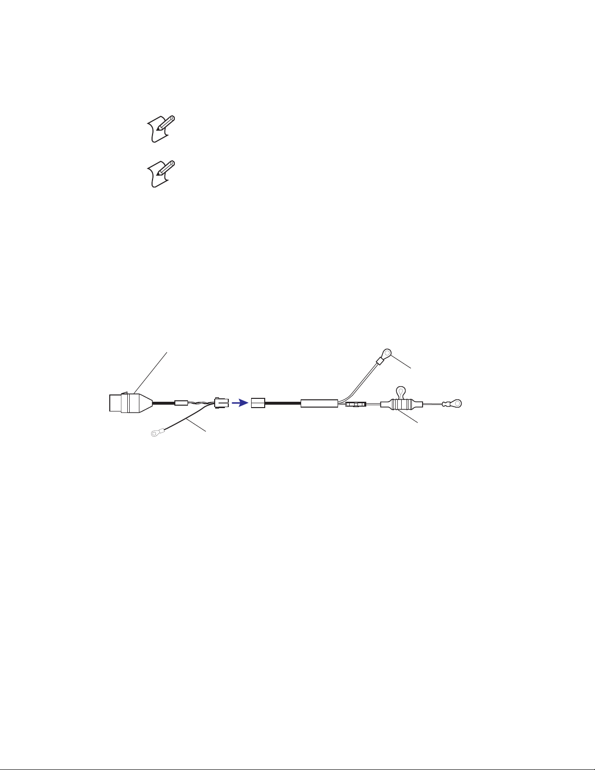
2 Start the vehicle engine. Continue monitoring the battery’s voltage
DC power cable
1.2 m (4 ft) - goes
to printer
P/N: 226-215-101
Vehicle battery cable
P/N: 206-875-00X
Ground strap
Part of install kit
P/N: 203-242-001
while you run the engine at a fast idle for five minutes. The voltage
should read below 14.5 V DC. It must not exceed 18.0 V.
Note: For 24 V vehicle systems check each battery individually.
Note: If the battery voltage exceeds 18.0 V DC, there is a problem with the
vehicle electrical system which must be diagnosed and repaired before the
printer and vehicle dock will work properly. Check your engine for a bad
voltage regulator or a poor ground, either of which cause excessive voltage.
Excess electrical noise can be severe enough to defeat the electrical filtering
that is built into Intermec cables, printers, and vehicle docks. Defective
ignition wiring, damaged insulation, or a faulty vehicle electrical
component can cause electrical noise — possibly causing unpredictable
behavior in printers and docks.
Installing the Direct-to-Battery Cable
Connect printers directly to the battery based on the following criteria:
• The vehicle battery acts as an electrical filter and regulator.
• If there is any damage to the printer dc power cable, the cable is easily
replaced.
Routing Cables
Use the following guidelines when routing the printer DC power cable and
the vehicle battery cable:
• Route the vehicle battery cable from the area where the printer is to be
mounted toward the vehicle battery.
• When possible, route the printer power cable along with existing vehicle
wiring. Use cable ties to join the cable and wiring together.
8 6820 Printer Installation Instructions
• Use a snap-in bushing (requires 9/16” hole) if the vehicle battery cable
passes through the firewall or other sheet-metal.
Page 9

• Make sure that cable routing does not interfere with other equipment or
vehicle controls.
• Ensure that cable routing does not invite damage to the cable.
• Secure the vehicle battery cable at least every 18” (50 cm) throughout
the cable run: use adjustable clamps (provided) or wire-tie to existing
vehicle cable runs.
• Completely install the printer power cable and take voltage
measurements before connecting the printer.
Preparing the Vehicle Battery Cable
After you route the vehicle battery cable to the vehicle battery, do the
following to prepare the vehicle battery cable for the terminal ring and fuse
link assembly.
Strip the Vehicle Battery Cable Jacket
To strip the gray vehicle battery cable jacket and insulation
1 Cut the gray battery cable near the battery to avoid coiling or tying
excess cable.
2 Strip the battery cable jacket (gray) back 12-14” (31-36 cm).
3 Strip 1/4” (6 mm) of insulation from the black (or brown) and red
wires.
Gray battery cable
P/N: 226-271-101
Red wire
Black (or brown)
wire
Strip each wire end
6 mm (0.25 in)
Strip each wire end
6 mm (0.25 in)
Crimping Cable Ends
To attach a terminal ring and a preassembled in-line fuse link to the vehicle battery
cable.
Note: You may have to shorten and restrip the red wire when attaching the
fuse link assembly.
1 Strip the black wire.
2 Crimp the 3/8” terminal ring (P/N 809-165-001) onto the black wire.
3 Attach the fuse link assembly (P/N 315-071-002) to the red wire (if
needed, shorten red wire), strip 1/4” (6 mm) of insulation off the red
wire.
6820 Printer Installation Instructions 9
Page 10

4 Crimp the red wire onto the fuse link.
9.525 mm
(0.37 in)
terminal ring
Black (or brown)
wire
Vehicle
battery
cable
Red
wire
Fuse link assembly
P/N: 236-107-001
Connecting to the Vehicle Battery
Your vehicle has either a top-mount battery with the terminals on the top, a
side-mount battery with terminals on the side, or two top-mount batteries
with the terminals on the top. Determine which battery is in your vehicle
and proceed with applicable instructions.
Connecting to a Side-Mount Vehicle Battery
To attach the vehicle battery cable to a side-mount battery terminal
1 Disconnect the negative battery cable, then disconnect the positive
battery cable, and remove the bolts from each cable.
2 Screw a 3/8” nut as far as it will go onto a 3/8” x 1-1/2” bolt furnished
in kit, then slip a 3/8” washer onto the bolt.
3 Slide the positive (red wire with fuse link) terminal ring from the printer
power cable onto the bolt.
4 Slip a second 3/8” washer, then slip the vehicle positive battery cable
onto the bolt.
5 Thread bolt assembly (Steps 2 through 4) into the positive (+) battery
terminal.
6 Securely tighten the bolt, then the nut installed in Step 2 to secure
washers and cables into place.
10 6820 Printer Installation Instructions
Page 11

7 Repeat Steps 2 through 6 for the negative vehicle battery cable wire
+
(black or brown), hooking up the negative cable to the negative battery
terminal.
Vehicle
battery
12V
9.52 mm (0.37 in) washer
9.52 mm (0.37 in)
x 1- 12.7 mm
(0.50 in) bolt
9.52 mm (0.37 in) nut
Vehicle
battery
cable
Connecting to a Top-Mount Vehicle Battery
To attach the vehicle battery cable to a top-mount battery terminal
1 Disconnect the negative battery cable, then disconnect the positive
battery cable.
2 Remove the bolts from the battery cable and replace these bolts with
3/8” x 1-1/2” bolts and nuts furnished in the installation kit.
3 Reinstall the positive battery cable, then tighten the nut securely.
4 Slip a 3/8” washer onto the extended end of each bolt.
5 Slide the positive (fuse link with red wire) terminal ring from the printer
power cable onto the positive (+) battery bolt.
6 Slip a second 3/8” washer onto the bolt, then thread and tighten a
second 3/8” nut onto that bolt.
6820 Printer Installation Instructions 11
Page 12

7 Repeat Steps 5 through 6 for the negative battery cable wire (black or
-
-
+
brown), connecting the wire to the negative battery terminal.
9.52 mm (0.37 in)
x 1- 12.7 mm
(0.50 in) bolt
9.52 mm (0.37 in)
washer (2 places)
9.52 mm (0.37 in) nut
12V
Fuse
holder
Vehicle
battery
cable
12 6820 Printer Installation Instructions
Page 13

Connecting to a Two Battery Vehicle System
-
-
-
-
V
The following illustration shows how to connect to a 24 V two battery
system by wiring the printer to one of the batteries.
Correct Connection Method
Positive
Negative
terminal
terminal
+
12V
To printer 12V
Negative
terminal
Positive
terminal
12V
-
To printer ground
Chassis ground
Negative
terminal
Positive
terminal
+
Negative
terminal
12V
-
+
Vehicle 24V
To printer 12V
Positive
terminal
12V
+
To printer 12
Chassis ground
Connecting to a Two Battery Vehicle System
Securing the Vehicle Battery Cable
6820 Printer Installation Instructions 13
To secure the vehicle battery cable
1 Secure the vehicle battery cable every 18” (50 cm) with adjustable cable
clamps. Work from the battery to the mounting area for the printer.
Page 14

2 Remove the paper backing from a clamp (P/N: 807-059-001) and stick
the clamp in place while drilling a pilot hole with a #26 drill bit. Use #6
sheet-metal screws to permanently hold clamps in place.
Grounding the Printer Power Cables
The printer power cable has a ground strap that must fasten to vehicle
sheet-metal to ensure proper cable shielding. This ground strap is the wire
with a ring terminal by the white connectors between the DC power cable
and the vehicle battery cable.
To fasten the ground strap:
1 Drill a small hole (slightly smaller than the screw diameter) where to
fasten the chassis ground strap for the power cable connector. Use a
punch to dimple and enlarge the hole.
2 Scrape a small circle of paint from around the hole to ensure a good
electrical connection.
3 Use a #8 x 5/8” screw and flat washer to secure the strap.
14 6820 Printer Installation Instructions
Page 15

Verifying the Printer Power Cable Voltage
Note: This is the correct polarity for 6820 Printers.
Verify the printer power cable voltage and polarity (as indicated), then plug
the printer DC power cable into the printer power connector.
+
Use a volt meter to test the cable before connecting the cable to the 6820
Printer. Set the voltmeter for DC volts.
Voltmeter Readings for Printer Power Cable
Voltmeter
Voltmeter
Red Lead
Pin 1 Pin 2 12-15 • If zero volts, check the battery connections.
Black
Lead
Reading
DC Volts
Meaning
• If a negative voltage, the wires on the battery are reversed. Do not
connect to printer.
• If less than 12 volts, vehicle battery or connections are bad
• If more than 15 volts, connection is across more than one 12-volt
battery or truck charging system is faulty. Do not connect to printer.
Pin 1 Pin 3 12-15 If zero volts, check the connection done on the previous page.
Pin 2Pin 30 If not zero volts, check the connection to the battery negative terminal
and the connection done on the previous page.
6820 Printer Installation Instructions 15
Page 16

Installing the Printer
Mounting keyhol
on oversize pape
Latch (x2)
The fixed mount printer and wall mount printer each has its own
mounting plate option. A mounting plate is not available for the portable
printer with the 50-sheet paper tray.
Fixed Mount Printer P/N 709-850-006 Mounting Plate (Optional)
The angle mounting plate and printer footprint are for the fixed mount
printers. Note the keyholes cut into the bottom of the oversize paper tray.
These keyholes allow you to install or remove the fixed mount printer from
a vehicle without using any special tools. Sliding latches in the tray bottom
hold the printer securely
Note: Nuts and bolts are not provided. You must locally select and purchase
hardware that provides the most secure installation possible for the application and vehicle.
16 6820 Printer Installation Instructions
Page 17

Once you select where to install the fixed mount printer in the vehicle, you
29.0 cm
(11.36 in)
19.0 cm
(7.32 in)
permanently install the plate. The following angle mounting plate has
access holes where necessary so special tools are not required for securely
tightening hardware.
Angle Mounting Plate (P/N 709-850-006)
6820 Printer Installation Instructions 17
Page 18

The following flat mounting plate has access holes where necessary so
special tools are not required for securely tightening hardware.
31.5 cm
(12.4 in)
34.3 cm
(13.5 in)
Flat Mounting Plate (P/N 709-966-006)
2.3 cm
(0.9 in)
18 6820 Printer Installation Instructions
Page 19

Wall Mount Printer Kits
754-548-002 Flat paper tray
714-417-001 Mounting plate
Contents of Flat Paper Tray - P/N 203-486-002
Part Number Description
754-548-002 Flat Paper Tray
714-417-001 Mounting Plate
801-194-003 6 1/4” - 20 1/2” bolts (3 needed)
803-041-000 6 1/4” split washers
754-546-002 Adapter bracket (discard)
6820 Printer Installation Instructions 19
The 714-417-001 Mounting Plate also includes a 5” x 4” plate adapter
bracket and knob.
Page 20

Contents of Compact Paper Tray - P/N 203-489-001
Part Number Description
650-447-001 Compact Paper Tray
801-194-003 2 1/4” - 20 1/2” bolts
803-041-000 2 1/2 split washers
650-447-001 Compact paper tray
20 6820 Printer Installation Instructions
Page 21

43 cm
(17 in)
66 cm
(26 in)
33 cm
(13 in)
You need a space that is 17” x 26” x 13” (43 cm x 66 cm x 33 cm) for the
mounting plate, wall mount printer, and flat paper tray.
6820 Printer Installation Instructions 21
Page 22

43 cm
(17 in)
56 cm
(22 in)
18 cm
(7 in)
17” x 22” x 7” (43 cm x 56 cm x 18 cm) is required for the mounting plate,
wall mount printer, and compact paper tray.
22 6820 Printer Installation Instructions
Page 23

Installing the Mounting Plate
33 cm
(13 in)
46 cm
(18 in)
Knob
screw
Knob
screw
The mounting plate for the wall mount printer hangs on the wall of a
vehicle. Install the plate with the knob screw on top and the mounting lips
facing outward. Use four bolts, evenly distributed, to secure the plate to the
vehicle wall. Note that the bolts are not included in the kit, you will have to
supply the bolts.
6820 Printer Installation Instructions 23
Page 24

Attaching Either Paper Tray to the Mounting Plate
Bottom lip on
mounting plate
Center lip on
at paper tray
Center lip on
compact paper tray
Use two bolts to attach either the flat paper tray or the compact paper tray
to the center, bottom lip of the mounting plate. The holes in the mounting
plate are threaded.
To attach to the mounting plate
1 Position the center lip on either paper tray over the center, bottom lip
on the mounting plate. The two holes in the paper tray should align
with the holes in the center, bottom lip of the mounting plate.
2 Hold either paper tray in place and insert two 1/4”-20 x 1/2” bolts (with
1/2” split washers) in the holes, through the paper tray. Use a 7/16”
wrench to tighten the bolts.
24 6820 Printer Installation Instructions
Page 25

Mounting the Printer
Knob
Plate
adaptor
bracket
Wall mount
printer
Mount the printer.ep
Bottom
lips on
mounting
plate assembly
Knob screw
on mounting
plate assembly
The wall mount printer sits on the bottom lip of the mounting plate. The
top of the printer is held to the plate via a 5” x 4” plate adaptor bracket and
a knob.
To mount the printer
1 Using the two slots on the printer bottom, push the printer onto the
two bottom lips on the mounting plate. Hold the printer against the
mounting plate.
2 Set the plate adaptor bracket into the horizontal slot at the top of the
printer, then align and turn the black knob clockwise onto the knob
screw to tighten the bracket onto the mounting plate
.
6820 Printer Installation Instructions 25
Page 26

Worldwide Headquarters
6001 36th Avenue West
Everett, Washington 98203
U.S.A.
tel 425.348.2600
fax 425.355.9551
www.intermec.com
©
2006 Intermec Technologies
Corporation. All rights reserved.
Worldwide Headquarters
6001 36th Avenue West
Everett, Washington 98203
U.S.A.
tel 425.348.2600
fax 425.355.9551
www.intermec.com
©
2007 Intermec Technologies
Corporation. All rights reserved.
6820 Printer Installation Instructions
*931-052-001*
P/N 931-052-001
 Loading...