

Page 1
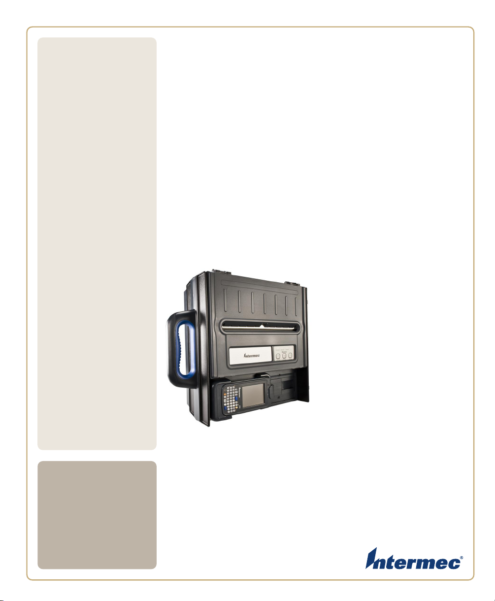
6820
User’s
Manual
Series 80-Column Printer
6822 Configuration
Page 2

Intermec Technologies Corporation
Worldwide Headquarters
6001 36th Ave.W.
Everett, WA 98203
U.S.A.
www.intermec.com
The information contained herein is provided solely for the purpose of allowing customers to operate and
service Intermec-manufactured equipment and is not to be released, reproduced, or used for any other
purpose without written permission of Intermec Technologies Corporation.
Information and specifications contained in this document are subject to change without prior notice and
do not represent a commitment on the part of Intermec Technologies Corporation.
© 2008-2009 by Intermec Technologies Corporation. All rights reserved.
The word Intermec, the Intermec logo, Norand, ArciTech, Beverage Routebook, CrossBar, dcBrowser,
Duratherm, EasyADC, EasyCoder, EasySet, Fingerprint, i-gistics, INCA (under license), Intellitag,
Intellitag Gen2, JANUS, LabelShop, MobileLAN, Picolink, Ready-to-Work, RoutePower, Sabre,
ScanPlus, ShopScan, Smart Mobile Computing, SmartSystems, TE 2000, Trakker Antares, and Vista
Powered are either trademarks or registered trademarks of Intermec Technologies Corporation.
There are U.S. and foreign patents as well as U.S. and foreign patents pending.
Wi-Fi is a registered certification mark of the Wi-Fi Alliance.
Microsoft, Windows, and the Windows logo are registered trademarks of Microsoft Corporation in the
United States and/or other countries.
Bluetooth is a trademark of Bluetooth SIG, Inc., U.S.A.
ii 6820 Series 80-Column Printer User’s Manual
Page 3

Document Change Record
This page records changes to this document. The document was
originally released as Revision 001.
Version
Number
002 2/2009 Revised cover to indicate the manual is for
Date Description of Change
the 6822 version of the 6820 series printer.
Other minor changes including copyright
date and process for downloading
documentation from the Intermec web site.
iii 6820 Series 80-Column Printer User’s Manual
Page 4

6820 Series 80-Column Printer User’s Manual iv
Page 5

Contents
Before You Begin . . . . . . . . . . . . . . . . . . . . . . . . . . . . . . . . . . . . . . . . . . . . . . . . . . . . . . . . . xii
Safety Information . . . . . . . . . . . . . . . . . . . . . . . . . . . . . . . . . . . . . . . . . . . . . . . . . xii
Global Services and Support. . . . . . . . . . . . . . . . . . . . . . . . . . . . . . . . . . . . . . . . . .xiii
Warranty Information. . . . . . . . . . . . . . . . . . . . . . . . . . . . . . . . . . . . . . . .xiii
Web Support. . . . . . . . . . . . . . . . . . . . . . . . . . . . . . . . . . . . . . . . . . . . . . .xiii
Telephone Support . . . . . . . . . . . . . . . . . . . . . . . . . . . . . . . . . . . . . . . . . .xiii
Service Location Support. . . . . . . . . . . . . . . . . . . . . . . . . . . . . . . . . . . . .xiii
Who Should Read This Document . . . . . . . . . . . . . . . . . . . . . . . . . . . . . . . . . . . . .xiv
Related Documents. . . . . . . . . . . . . . . . . . . . . . . . . . . . . . . . . . . . . . . . . . . . . . . . . xiv
Patent Information . . . . . . . . . . . . . . . . . . . . . . . . . . . . . . . . . . . . . . . . . . . . . . . . .xiv
Using the 6820 80-Column Printer . . . . . . . . . . . . . . . . . . . . . . . . . . . . . . . . . . . . 1
1
Learning About the Printer Models. . . . . . . . . . . . . . . . . . . . . . . . . . . . . . . . . . . . . . . . . . . . . 2
Guidelines for Operating the Printer. . . . . . . . . . . . . . . . . . . . . . . . . . . . . . . . . . . . . . . . . . . . 3
Understanding the Control Panel . . . . . . . . . . . . . . . . . . . . . . . . . . . . . . . . . . . . . . . . . . . . . . 3
Using the Reset Button . . . . . . . . . . . . . . . . . . . . . . . . . . . . . . . . . . . . . . . . . . . . . . . . . . . . . . 5
Contents
Understanding the Power Supply Options . . . . . . . . . . . . . . . . . . . . . . . . . . . . . . . . . . . . . . . 6
Using the Internal Battery. . . . . . . . . . . . . . . . . . . . . . . . . . . . . . . . . . . . . . . . . . . . . 6
Connecting to a Vehicle Power Supply. . . . . . . . . . . . . . . . . . . . . . . . . . . . . . . . . . . 6
Connecting to a DC Power Source. . . . . . . . . . . . . . . . . . . . . . . . . . . . . . . . . . . . . . 7
Fixed Mount Printer . . . . . . . . . . . . . . . . . . . . . . . . . . . . . . . . . . . . . . . . . . 7
Portable Printer. . . . . . . . . . . . . . . . . . . . . . . . . . . . . . . . . . . . . . . . . . . . . . 7
Installing the 6820 Printer. . . . . . . . . . . . . . . . . . . . . . . . . . . . . . . . . . . . . . . . . . . . . 9
2
Installing the Internal Battery . . . . . . . . . . . . . . . . . . . . . . . . . . . . . . . . . . . . . . . . . . . . . . . . 10
Installing the Ribbon Cartridge. . . . . . . . . . . . . . . . . . . . . . . . . . . . . . . . . . . . . . . . . . . . . . . 11
Adjusting the Printhead Gap. . . . . . . . . . . . . . . . . . . . . . . . . . . . . . . . . . . . . . . . . . . . . . . . . 12
Loading the Paper Tray. . . . . . . . . . . . . . . . . . . . . . . . . . . . . . . . . . . . . . . . . . . . . . . . . . . . . 13
Loading Paper in the Printer . . . . . . . . . . . . . . . . . . . . . . . . . . . . . . . . . . . . . . . . . . . . . . . . . 14
6820 Series 80-Column Printer User’s Manual v
Page 6

Contents
Positioning the Paper . . . . . . . . . . . . . . . . . . . . . . . . . . . . . . . . . . . . . . . . . . . . . . . 1 4
Adjusting the Pinfeed Holders . . . . . . . . . . . . . . . . . . . . . . . . . . . . . . . . . . . . . . . . 15
Inserting a Computer in the Terminal Holder. . . . . . . . . . . . . . . . . . . . . . . . . . . . . . . . . . . . 17
Configuring the 6820 Printer . . . . . . . . . . . . . . . . . . . . . . . . . . . . . . . . . . . . . . . . . 19
3
Connecting to the Printer. . . . . . . . . . . . . . . . . . . . . . . . . . . . . . . . . . . . . . . . . . . . . . . . . . . . 20
Understanding the Font Modules . . . . . . . . . . . . . . . . . . . . . . . . . . . . . . . . . . . . . . . . . . . . . 20
Using the Printer Configuration Utility. . . . . . . . . . . . . . . . . . . . . . . . . . . . . . . . . . . . . . . . . 21
Installing the Printer Configuration Utility. . . . . . . . . . . . . . . . . . . . . . . . . . . . . . . 21
Disabling the Microsoft ActiveSync Serial Port Connections . . . . . . . . . . . . . . . . 25
Operating the Printer Configuration Utility . . . . . . . . . . . . . . . . . . . . . . . . . . . . . . 25
Communicating with the Printer. . . . . . . . . . . . . . . . . . . . . . . . . . . . . . . . . . . . . . . 27
Setting the 6820 Configuration . . . . . . . . . . . . . . . . . . . . . . . . . . . . . . . . 29
Default Printer Settings . . . . . . . . . . . . . . . . . . . . . . . . . . . . . . . . . . . . . . 33
Error Messages . . . . . . . . . . . . . . . . . . . . . . . . . . . . . . . . . . . . . . . . . . . . . . . . . . . . 33
Connecting to the Bluetooth Adapter . . . . . . . . . . . . . . . . . . . . . . . . . . . . . . . . . . . 34
Enable Microsoft ActiveSync Serial Port Connection . . . . . . . . . . . . . . . . . . . . . . 34
Control Code Definitions. . . . . . . . . . . . . . . . . . . . . . . . . . . . . . . . . . . . . . . . . . . . . . 35
4
Understanding Control Code Definitions . . . . . . . . . . . . . . . . . . . . . . . . . . . . . . . . . . . . . . . 36
I/O Buffer . . . . . . . . . . . . . . . . . . . . . . . . . . . . . . . . . . . . . . . . . . . . . . . . . . . . . . . . 36
Print Image Buffer . . . . . . . . . . . . . . . . . . . . . . . . . . . . . . . . . . . . . . . . . . . . . . . . . 36
Special Notations . . . . . . . . . . . . . . . . . . . . . . . . . . . . . . . . . . . . . . . . . . . . . . . . . . 36
Using Printer Control Codes. . . . . . . . . . . . . . . . . . . . . . . . . . . . . . . . . . . . . . . . . . . . . . . . . 37
Backspace . . . . . . . . . . . . . . . . . . . . . . . . . . . . . . . . . . . . . . . . . . . . . . . . . . . . . . . . 37
Beeper. . . . . . . . . . . . . . . . . . . . . . . . . . . . . . . . . . . . . . . . . . . . . . . . . . . . . . . . . . . 37
Cancel Line. . . . . . . . . . . . . . . . . . . . . . . . . . . . . . . . . . . . . . . . . . . . . . . . . . . . . . . 38
Carriage Return. . . . . . . . . . . . . . . . . . . . . . . . . . . . . . . . . . . . . . . . . . . . . . . . . . . . 38
Delete . . . . . . . . . . . . . . . . . . . . . . . . . . . . . . . . . . . . . . . . . . . . . . . . . . . . . . . . . . . 38
Form Feed. . . . . . . . . . . . . . . . . . . . . . . . . . . . . . . . . . . . . . . . . . . . . . . . . . . . . . . . 39
Select Half-Speed Printing . . . . . . . . . . . . . . . . . . . . . . . . . . . . . . . . . . . . . . . . . . . 39
Cancel Half-Speed Printing . . . . . . . . . . . . . . . . . . . . . . . . . . . . . . . . . . . . . . . . . . 39
Set Inactivity Time for Sleep Mode . . . . . . . . . . . . . . . . . . . . . . . . . . . . . . . . . . . . 40
Line Feed . . . . . . . . . . . . . . . . . . . . . . . . . . . . . . . . . . . . . . . . . . . . . . . . . . . . . . . . 40
Perform Line Feed . . . . . . . . . . . . . . . . . . . . . . . . . . . . . . . . . . . . . . . . . . 40
Perform n/216-inch Line Feed . . . . . . . . . . . . . . . . . . . . . . . . . . . . . . . . . 40
Perform n/216-inch Reverse Line Feed . . . . . . . . . . . . . . . . . . . . . . . . . . 41
Perform Master Reset . . . . . . . . . . . . . . . . . . . . . . . . . . . . . . . . . . . . . . . . . . . . . . . 41
vi 6820 Series 80-Column Printer User’s Manual
Page 7

Contents
Set Print Position (absolute) . . . . . . . . . . . . . . . . . . . . . . . . . . . . . . . . . . . . . . . . . . 41
Set Print Position (relative) . . . . . . . . . . . . . . . . . . . . . . . . . . . . . . . . . . . . . . . . . . . 42
Select Top-Down Printing . . . . . . . . . . . . . . . . . . . . . . . . . . . . . . . . . . . . 42
Select Bottom-Up Printing. . . . . . . . . . . . . . . . . . . . . . . . . . . . . . . . . . . . 42
Select Unidirectional Printing . . . . . . . . . . . . . . . . . . . . . . . . . . . . . . . . . 43
Cancel Unidirectional Printing. . . . . . . . . . . . . . . . . . . . . . . . . . . . . . . . . 43
Select Unidirectional (one line) Printing . . . . . . . . . . . . . . . . . . . . . . . . . 43
Page Formatting Functions. . . . . . . . . . . . . . . . . . . . . . . . . . . . . . . . . . . . . . . . . . . 44
Set Page Length (lines). . . . . . . . . . . . . . . . . . . . . . . . . . . . . . . . . . . . . . . 44
Set Page Length (inches) . . . . . . . . . . . . . . . . . . . . . . . . . . . . . . . . . . . . . 44
Select 7/72-inch Line Spacing (7 dots) . . . . . . . . . . . . . . . . . . . . . . . . . . 45
Select 1/6-inch Line Spacing . . . . . . . . . . . . . . . . . . . . . . . . . . . . . . . . . . 45
Select n/216-inch Line Spacing . . . . . . . . . . . . . . . . . . . . . . . . . . . . . . . . 45
Select n/72-inch Line Spacing (n dots) . . . . . . . . . . . . . . . . . . . . . . . . . . 46
Set Right Margin . . . . . . . . . . . . . . . . . . . . . . . . . . . . . . . . . . . . . . . . . . . 46
Set Left Margin. . . . . . . . . . . . . . . . . . . . . . . . . . . . . . . . . . . . . . . . . . . . . 46
Set Skip Over Perforation. . . . . . . . . . . . . . . . . . . . . . . . . . . . . . . . . . . . . 47
Cancel Skip Over Perforation. . . . . . . . . . . . . . . . . . . . . . . . . . . . . . . . . . 47
Character Style and Text Mode Functions . . . . . . . . . . . . . . . . . . . . . . . . . . . . . . . 48
Select Condensed Character Mode. . . . . . . . . . . . . . . . . . . . . . . . . . . . . . 48
Cancel Condensed Character Mode . . . . . . . . . . . . . . . . . . . . . . . . . . . . . 48
Select Double-Strike Mode . . . . . . . . . . . . . . . . . . . . . . . . . . . . . . . . . . . 49
Cancel Double-Strike Mode. . . . . . . . . . . . . . . . . . . . . . . . . . . . . . . . . . . 49
Select Double-Wide Mode. . . . . . . . . . . . . . . . . . . . . . . . . . . . . . . . . . . . 50
Cancel Double-Wide Print . . . . . . . . . . . . . . . . . . . . . . . . . . . . . . . . . . . . 50
Select Double-Wide Print. . . . . . . . . . . . . . . . . . . . . . . . . . . . . . . . . . . . . 51
Cancel Double-Wide Print . . . . . . . . . . . . . . . . . . . . . . . . . . . . . . . . . . . . 51
Select Elite Pitch. . . . . . . . . . . . . . . . . . . . . . . . . . . . . . . . . . . . . . . . . . . . 51
Select Emphasized Print Mode. . . . . . . . . . . . . . . . . . . . . . . . . . . . . . . . . 52
Cancel Emphasized Print Mode . . . . . . . . . . . . . . . . . . . . . . . . . . . . . . . . 52
Define Intercharacter Space . . . . . . . . . . . . . . . . . . . . . . . . . . . . . . . . . . . 52
Select Italic Mode. . . . . . . . . . . . . . . . . . . . . . . . . . . . . . . . . . . . . . . . . . . 53
Cancel Italic Mode . . . . . . . . . . . . . . . . . . . . . . . . . . . . . . . . . . . . . . . . . . 53
Master Select . . . . . . . . . . . . . . . . . . . . . . . . . . . . . . . . . . . . . . . . . . . . . . 53
Select Pica Pitch. . . . . . . . . . . . . . . . . . . . . . . . . . . . . . . . . . . . . . . . . . . . 55
Select Superscript Mode. . . . . . . . . . . . . . . . . . . . . . . . . . . . . . . . . . . . . . 55
Select Subscript Mode . . . . . . . . . . . . . . . . . . . . . . . . . . . . . . . . . . . . . . . 55
Cancel Subscript/Superscript Mode. . . . . . . . . . . . . . . . . . . . . . . . . . . . . 56
Select Underline Mode. . . . . . . . . . . . . . . . . . . . . . . . . . . . . . . . . . . . . . . 56
Cancel Underline Mode . . . . . . . . . . . . . . . . . . . . . . . . . . . . . . . . . . . . . . 56
Tabs and Tab Setting Functions . . . . . . . . . . . . . . . . . . . . . . . . . . . . . . . . . . . . . . . 57
Perform Horizontal Tab . . . . . . . . . . . . . . . . . . . . . . . . . . . . . . . . . . . . . . 57
Set Horizontal Tabs . . . . . . . . . . . . . . . . . . . . . . . . . . . . . . . . . . . . . . . . . 58
Clear Horizontal Tabs. . . . . . . . . . . . . . . . . . . . . . . . . . . . . . . . . . . . . . . . 58
Perform Vertical Tab . . . . . . . . . . . . . . . . . . . . . . . . . . . . . . . . . . . . . . . . 58
Set Vertical Tabs . . . . . . . . . . . . . . . . . . . . . . . . . . . . . . . . . . . . . . . . . . . 59
Clear Vertical Tabs. . . . . . . . . . . . . . . . . . . . . . . . . . . . . . . . . . . . . . . . . . 59
6820 Series 80-Column Printer User’s Manual vii
Page 8

Contents
Set Vertical Tabs in Channel . . . . . . . . . . . . . . . . . . . . . . . . . . . . . . . . . . 59
Clear Vertical Tabs in Channel . . . . . . . . . . . . . . . . . . . . . . . . . . . . . . . . 60
Select Vertical Tab Channel. . . . . . . . . . . . . . . . . . . . . . . . . . . . . . . . . . . 60
Using Character Sets and User-Defined Functions . . . . . . . . . . . . . . . . . . . . . . . . 60
Single-Byte Character Sets. . . . . . . . . . . . . . . . . . . . . . . . . . . . . . . . . . . . 61
Double-Byte Character Sets. . . . . . . . . . . . . . . . . . . . . . . . . . . . . . . . . . . 61
Multi-Byte Character Sets . . . . . . . . . . . . . . . . . . . . . . . . . . . . . . . . . . . . 61
Select National Character Set. . . . . . . . . . . . . . . . . . . . . . . . . . . . . . . . . . 62
Hebrew Character Set. . . . . . . . . . . . . . . . . . . . . . . . . . . . . . . . . . . . . . . . 63
Greek Character Set . . . . . . . . . . . . . . . . . . . . . . . . . . . . . . . . . . . . . . . . . 64
User Defined Characters. . . . . . . . . . . . . . . . . . . . . . . . . . . . . . . . . . . . . . . . . . . . . 65
Copy ROM to RAM. . . . . . . . . . . . . . . . . . . . . . . . . . . . . . . . . . . . . . . . . 65
Define User Defined Characters. . . . . . . . . . . . . . . . . . . . . . . . . . . . . . . . 65
Select User-Defined Character Set. . . . . . . . . . . . . . . . . . . . . . . . . . . . . . 66
Select Default Character Set. . . . . . . . . . . . . . . . . . . . . . . . . . . . . . . . . . . 67
Enable Printing of Codes 128-159 . . . . . . . . . . . . . . . . . . . . . . . . . . . . . . 67
Disable Printing of Codes 128-159 . . . . . . . . . . . . . . . . . . . . . . . . . . . . . 68
Expand Printable Code Area . . . . . . . . . . . . . . . . . . . . . . . . . . . . . . . . . . 68
Enable Printing of Character Graphics. . . . . . . . . . . . . . . . . . . . . . . . . . . 69
Disable Printing of Character Graphics . . . . . . . . . . . . . . . . . . . . . . . . . . 70
Enable Printing of Character Graphics. . . . . . . . . . . . . . . . . . . . . . . . . . . 70
Graphics Functions . . . . . . . . . . . . . . . . . . . . . . . . . . . . . . . . . . . . . . . . . . . . . . . . . 71
Select Graphics Mode. . . . . . . . . . . . . . . . . . . . . . . . . . . . . . . . . . . . . . . . 72
Reassign Graphics Mode . . . . . . . . . . . . . . . . . . . . . . . . . . . . . . . . . . . . . 72
Select Single Density Graphics Mode . . . . . . . . . . . . . . . . . . . . . . . . . . . 73
Select Low-Speed Double Density Graphics Mode. . . . . . . . . . . . . . . . . 73
Select High-Speed Double Density Graphics Mode . . . . . . . . . . . . . . . . 73
Select Low-Speed Quadruple Density Graphics Mode . . . . . . . . . . . . . . 74
Select 9-Pin Single Density Graphics Mode . . . . . . . . . . . . . . . . . . . . . . 75
Select 9-Pin Double Density Graphics Mode. . . . . . . . . . . . . . . . . . . . . . 75
Troubleshooting and Maintaining the 6820 . . . . . . . . . . . . . . . . . . . . . . . . 77
5
Troubleshooting Basics. . . . . . . . . . . . . . . . . . . . . . . . . . . . . . . . . . . . . . . . . . . . . . . . . . . . . 78
Checking the Power Source . . . . . . . . . . . . . . . . . . . . . . . . . . . . . . . . . . . . . . . . . . 78
Testing the Printer. . . . . . . . . . . . . . . . . . . . . . . . . . . . . . . . . . . . . . . . . . . . . . . . . . 78
Testing Communications/PC . . . . . . . . . . . . . . . . . . . . . . . . . . . . . . . . . . 79
Aligning the Printer Mechanism. . . . . . . . . . . . . . . . . . . . . . . . . . . . . . . . . . . . . . . . . . . . . . 80
Understanding Printer Errors . . . . . . . . . . . . . . . . . . . . . . . . . . . . . . . . . . . . . . . . . . . . . . . . 81
Runtime Errors . . . . . . . . . . . . . . . . . . . . . . . . . . . . . . . . . . . . . . . . . . . . . . . . . . . . 81
Troubleshooting Using the Power-On-Self-Test (POST) . . . . . . . . . . . . . . . . . . . . 83
Understanding Fatal Errors. . . . . . . . . . . . . . . . . . . . . . . . . . . . . . . . . . . . . . . . . . . 84
Flash Write Errors . . . . . . . . . . . . . . . . . . . . . . . . . . . . . . . . . . . . . . . . . . 84
viii 6820 Series 80-Column Printer User’s Manual
Page 9

EEPROM Configuration Block Errors. . . . . . . . . . . . . . . . . . . . . . . . . . . 85
Troubleshooting Using the Printer Self-Test. . . . . . . . . . . . . . . . . . . . . . . . . . . . . . . . . . . . . 85
Self Test Function Descriptions . . . . . . . . . . . . . . . . . . . . . . . . . . . . . . . . . . . . . . . 85
Performing a Printer Self-Test . . . . . . . . . . . . . . . . . . . . . . . . . . . . . . . . . . . . . . . . 86
Running the Self-Test . . . . . . . . . . . . . . . . . . . . . . . . . . . . . . . . . . . . . . . . . . . . . . . 86
Understanding the Self-Test Report . . . . . . . . . . . . . . . . . . . . . . . . . . . . . . . . . . . . 86
Miscellaneous Troubleshooting Tips . . . . . . . . . . . . . . . . . . . . . . . . . . . . . . . . . . . 90
Understanding Diagnostic Information. . . . . . . . . . . . . . . . . . . . . . . . . . . . . . . . . . . . . . . . . 93
Cable Configurations. . . . . . . . . . . . . . . . . . . . . . . . . . . . . . . . . . . . . . . . . . . . . . . . . . . . . . . 98
Cleaning the Printer Case . . . . . . . . . . . . . . . . . . . . . . . . . . . . . . . . . . . . . . . . . . . . . . . . . . 103
Cleaning the Outside of the Case . . . . . . . . . . . . . . . . . . . . . . . . . . . . . . . . . . . . . 104
Cleaning the Inside the Case. . . . . . . . . . . . . . . . . . . . . . . . . . . . . . . . . . . . . . . . . 104
Changing the Ribbon Cartridge. . . . . . . . . . . . . . . . . . . . . . . . . . . . . . . . . . . . . . . . . . . . . . 105
Cleaning the Mask Spring. . . . . . . . . . . . . . . . . . . . . . . . . . . . . . . . . . . . . . . . . . . . . . . . . . 106
Specifications . . . . . . . . . . . . . . . . . . . . . . . . . . . . . . . . . . . . . . . . . . . . . . . . . . . . . . . . 111
A
Specifications . . . . . . . . . . . . . . . . . . . . . . . . . . . . . . . . . . . . . . . . . . . . . . . . . . . . . . . . . . . 112
Contents
Printer Dimensions . . . . . . . . . . . . . . . . . . . . . . . . . . . . . . . . . . . . . . . . . . . . . . . . . . . . . . . 113
Fixed Mount Printer . . . . . . . . . . . . . . . . . . . . . . . . . . . . . . . . . . . . . . . . . . . . . . . 113
Portable Printer . . . . . . . . . . . . . . . . . . . . . . . . . . . . . . . . . . . . . . . . . . . . . . . . . . . 114
Media Specifications. . . . . . . . . . . . . . . . . . . . . . . . . . . . . . . . . . . . . . . . . . . . . . . . . . . . . . 114
Material Breakdown . . . . . . . . . . . . . . . . . . . . . . . . . . . . . . . . . . . . . . . . . . . . . . . 114
Caliper Breakdown . . . . . . . . . . . . . . . . . . . . . . . . . . . . . . . . . . . . . . . . . . . . . . . . 116
Understanding the Fanfold Paper Page Layout. . . . . . . . . . . . . . . . . . . . . . . . . . . . . . . . . . 117
Bluetooth Configuration Commands and Specifications. . . . . . . . . 119
B
Using Configuration Commands. . . . . . . . . . . . . . . . . . . . . . . . . . . . . . . . . . . . . . . . . . . . . 120
Operating Modes. . . . . . . . . . . . . . . . . . . . . . . . . . . . . . . . . . . . . . . . . . . . . . . . . . 121
Command and Control Modes . . . . . . . . . . . . . . . . . . . . . . . . . . . . . . . . . . . . . . . 122
Set Local Bluetooth Device Name. . . . . . . . . . . . . . . . . . . . . . . . . . . . . 123
Set Class of Device/Service Field . . . . . . . . . . . . . . . . . . . . . . . . . . . . . 123
Set Service Name . . . . . . . . . . . . . . . . . . . . . . . . . . . . . . . . . . . . . . . . . . 123
Connectable On/Off . . . . . . . . . . . . . . . . . . . . . . . . . . . . . . . . . . . . . . . . 124
6820 Series 80-Column Printer User’s Manual ix
Page 10

Contents
Specify Page Scan Timing . . . . . . . . . . . . . . . . . . . . . . . . . . . . . . . . . . . 124
Enable Discoverable . . . . . . . . . . . . . . . . . . . . . . . . . . . . . . . . . . . . . . . 124
Specify Inquiry Scan Timing . . . . . . . . . . . . . . . . . . . . . . . . . . . . . . . . . 125
Set Encryption/Authentication Pin Code . . . . . . . . . . . . . . . . . . . . . . . . 125
Manage Security Modes . . . . . . . . . . . . . . . . . . . . . . . . . . . . . . . . . . . . 125
Read Module Version . . . . . . . . . . . . . . . . . . . . . . . . . . . . . . . . . . . . . . 126
Read Local Device Address . . . . . . . . . . . . . . . . . . . . . . . . . . . . . . . . . 127
Set Shutdown Timing . . . . . . . . . . . . . . . . . . . . . . . . . . . . . . . . . . . . . . 127
Clear Link Key Table . . . . . . . . . . . . . . . . . . . . . . . . . . . . . . . . . . . . . . 127
Understanding Adapter States or Modes. . . . . . . . . . . . . . . . . . . . . . . . . . . . . . . . . . . . . . . 128
700 Series or CK60 to 6820 Pass Through . . . . . . . . . . . . . . . . . . . . . . . . . . . . . 129
700 Series, CK60, or CN3 to Bluetooth Module Communication Interface . . . . 129
Radio Power On/Off Mechanism . . . . . . . . . . . . . . . . . . . . . . . . . . . . . . . . . . . . . 129
Persistent Storage . . . . . . . . . . . . . . . . . . . . . . . . . . . . . . . . . . . . . . . . . . . . . . . . . . . . . . . . 130
System Behavior/Software Considerations. . . . . . . . . . . . . . . . . . . . . . . . . . . . . . . . . . . . . 130
Remote Configuration. . . . . . . . . . . . . . . . . . . . . . . . . . . . . . . . . . . . . . . . . . . . . . . . . . . . . 131
Bluetooth Performance. . . . . . . . . . . . . . . . . . . . . . . . . . . . . . . . . . . . . . . . . . . . . 132
Diagnostic Capabilities . . . . . . . . . . . . . . . . . . . . . . . . . . . . . . . . . . . . . . . . . . . . . . . . . . . . 132
Using the Information Application . . . . . . . . . . . . . . . . . . . . . . . . . . . . . . . . . . . . . . . . . . . 132
System Qualification. . . . . . . . . . . . . . . . . . . . . . . . . . . . . . . . . . . . . . . . . . . . . . . . . . . . . . 134
Operation Resilience. . . . . . . . . . . . . . . . . . . . . . . . . . . . . . . . . . . . . . . . . . . . . . . 134
Specifications . . . . . . . . . . . . . . . . . . . . . . . . . . . . . . . . . . . . . . . . . . . . . . . . . . . . 134
Default Bluetooth Configuration Settings. . . . . . . . . . . . . . . . . . . . . . . . . . . . . . . . . . . . . . 136
Cross-Reference Tables . . . . . . . . . . . . . . . . . . . . . . . . . . . . . . . . . . . . . . . . . . . . . . 137
C
Single Character Control Codes . . . . . . . . . . . . . . . . . . . . . . . . . . . . . . . . . . . . . . . . . . . . . 138
Escape Sequence Quick Reference. . . . . . . . . . . . . . . . . . . . . . . . . . . . . . . . . . . . . . . . . . . 140
Factory-Installed Printer Defaults . . . . . . . . . . . . . . . . . . . . . . . . . . . . . . . . . . . . . . . . . . . 143
Printer Font Test Jobs. . . . . . . . . . . . . . . . . . . . . . . . . . . . . . . . . . . . . . . . . . . . . . . . 145
D
About the Printer Font Jobs. . . . . . . . . . . . . . . . . . . . . . . . . . . . . . . . . . . . . . . . . . . . . . . . . 146
x 6820 Series 80-Column Printer User’s Manual
Page 11

Contents
Big 5 Traditional Chinese Character Set . . . . . . . . . . . . . . . . . . . . . . . . . . . . . . . . . . . . . . 146
Simplified Chinese Character Set . . . . . . . . . . . . . . . . . . . . . . . . . . . . . . . . . . . . . . . . . . . 147
IBM 437 Code Page Character Set . . . . . . . . . . . . . . . . . . . . . . . . . . . . . . . . . . . . . . . . . . 147
Japanese (JIS) Character Set . . . . . . . . . . . . . . . . . . . . . . . . . . . . . . . . . . . . . . . . . . . . . . . 147
Korean Character Set . . . . . . . . . . . . . . . . . . . . . . . . . . . . . . . . . . . . . . . . . . . . . . . . . . . . . 148
International Character Set . . . . . . . . . . . . . . . . . . . . . . . . . . . . . . . . . . . . . . . . . . . . . . . . . 148
Index . . . . . . . . . . . . . . . . . . . . . . . . . . . . . . . . . . . . . . . . . . . . . . . . . . . . . . . . . . . . . . . . . . . . 149
I
6820 Series 80-Column Printer User’s Manual xi
Page 12
Before You Begin
Before You Begin
This section provides you with safety information, technical support
information, and sources for additional product information.
Safety Information
Your safety is extremely important. Read and follow all warnings and
cautions in this document before handling and operating Intermec
equipment. You can be seriously injured, and equipment and data can be
damaged if you do not follow the safety warnings and cautions.
This section explains how to identify and understand dangers, warnings,
cautions, and notes that are in this document. You may also see icons
which tell you when to follow ESD procedures.
A warning alerts you of an operating procedure, practice,
condition, or statement that must be strictly observed to
avoid death or serious injury to the persons working on the
equipment.
A caution alerts you to an operating procedure, practice,
condition, or statement that must be strictly observed to
prevent equipment damage or destruction, or corruption or
loss of data.
This icon appears at the beginning of any procedure in this
manual that could cause you to touch components (such as
printed circuit boards) that are susceptible to damage from
electrostatic discharge (ESD). When you see this icon, you
must follow standard ESD guidelines to avoid damaging
the equipment you are using.
Note: Notes either provide extra information about a topic or
contain special instructions for handling a particular condition
or set of circumstances.
xii 6820 Series 80-Column Printer User’s Manual
Page 13

Global Services and Support
Warranty Information
T o understand the warranty for you r Intermec product, visit the Intermec
web site at www.interme c.com and click Service & Support > Warranty.
Web Support
Visit the Intermec web site atwww.intermec.com to download our
current manuals (in PDF). To order printed versions of the Intermec
manuals, contact your local Intermec representative or distributor.
Visit the Intermec technical knowledge base (Knowledge Central) at
intermec.custhelp.com to review technical information or to request
technical support for your Intermec product.
Telephone Support
In the U.S.A. and Canada, call 1-800-755-5505.
Outside the U.S.A. and Canada, contact your local Intermec
representative. T o search for your local representative, from the Intermec
web site, click About Us > Contact Us.
Before You Begin
Service Location Support
For the most current listing of service locations, from the Intermec web
site, click Support >Returns and Repairs > Repair Locations.
For technical support in South Korea, use the after service locations
listed below:
AWOO Systems
102-1304 SK Ventium
522 Dangjung-dong
Gunpo-si, Gyeonggi-do Korea, South 435-776
Contact: Mr. Sinbum Kang
Telephone: +82-31-436-1191
Email: mjyun@awoo.co.kr
IN Information System PTD LTD
6th Floor
Daegu Venture Center Bldg 95
Shinchun 3 Dong
Donggu, Daegu City, Korea
E-mail: jmyou@idif.co.kr or korlim@gw.idif.co.kr
6820 Series 80-Column Printer User’s Manual xiii
Page 14

Before You Begin
Who Should Read This Document
This user’s guide provides you with information about the features of the
6820 Series printers, and how to install, configure, operate, maintain,
and troubleshoot them.
Related Documents
The Intermec web site at www.intermec.com contains our documents
(as PDF files) that you can download for free.
To downlo a d documents
1 Visit the Intermec web site at www.intermec.com.
2 Click Support > Manuals.
3 Use the Product Category field, the Product Family field, and the
Product field to help you locate the product whose documentation
you want to download.
Patent Information
This product is protected by one or more of the following United States
patents:
5,581,293; 5,613,790; 5,927,876; 6,088,049; 6,345,920
There may be U.S. and Foreign Patents Pending.
xiv 6820 Series 80-Column Printer User’s Manual
Page 15

1
Using the 6820 80-Column
Printer
Use this chapter to familiarize yourself with the 6820 printer.
In this chapter you will find these sections:
• Learning About the Printer Models
• Guidelines for Operating the Printer
• Understanding the Control Panel
• Understanding the Power Supply Options
6820 Series 80-Column Printer User’s Manual 1
Page 16

Chapter 1 — Using the 6820 80-Column Printer
Learning About the Printer Models
The 6820 printer is used in the route accounting industry to produce
high-quality customer invoices, receipts, load reports, transfers, and
other documents. A unique “sleep” feature saves energy when the printer
is not printing, eliminating the need for an On/Off switch. Data input is
normally provided by mobile computers.
The 6820 printer is available in the following models:
• Fixed Mount Printer
The fixed mount printer is mounted in motor vehicles or used in a
work location. The terminal holder may be mounted on the printer or
a remote dock can connect to the side of the printer. A deep paper
tray, which holds up to 200 3-ply forms (up to 5 cm or 2 in of paper)
is located under the printer mechanism.
• Portable Printer
The portable printer has a handle so that you can carry it. An optional
internal battery permits operation without the use of an external
power source. The terminal holder is an integral part of this printer. A
shallow paper tray , which holds up to 50 3-ply forms (up to 2.5 cm or
1.0 in of paper) is located under the printer mechanism.
Note: The printer models are shown on page 7.
The discharge of electrostatic energy accumulated on the human
body, clothing, or other surfaces can damage or destroy the
printhead or electronic components used in this printer. Avoid
touching the electrical connectors while unpacking or setting up
your printer.
2 6820 Series 80-Column Printer User’s Manual
Page 17
Chapter 1 — Using the 6820 80-Column Printer
Guidelines for Operating the Printer
• Make sure that your mobile computer remains connected to the
printer when printing or operating.
• Keep the printer cover closed except during maintenance or when
loading paper.
• Make sure the paper is properly installed in the paper tray or
dashboard mount.
• Disconnect the printer power cable when jump-starting the vehicle.
• Make sure your printer is loaded with paper before communicating
with your mobile computer.
• Do not spill liquids or food crumbs into the printer.
• Do not use solvents or abrasive cleaners on the printer.
• Do not rest objects on, under, or against the printer.
• If the printer is attached to a vehicle electrical system, do not start or
stop the vehicle engine while you are printing.
• Do not overload the paper tray or paper jams will occur.
Understanding the Control Panel
The printer control panel has four status indicators in the top row and
three buttons in the bottom row . Three status indicators blink when there
is a problem with the printer. Use the three buttons to adjust and align
paper in the printer.
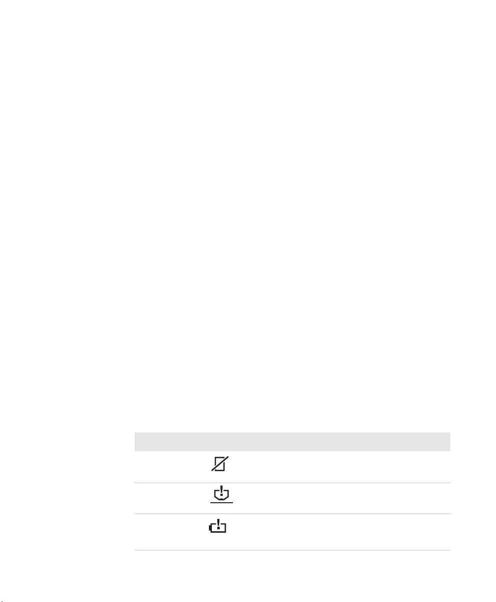
Understanding the Status Indicators
Name Indicator Description
Paper Out The printer is out of paper.
Head Jam The printhead is jammed and cannot
move.
Low Battery The internal battery voltage, the vehicle
battery voltage, or the power module
voltage is too low.
6820 Series 80-Column Printer User’s Manual 3
Page 18
Chapter 1 — Using the 6820 80-Column Printer
FORM FEED
LINE FEED
Understanding the Status Indicators (continued)
Name Indicator Description
Power The power LED turns green when you
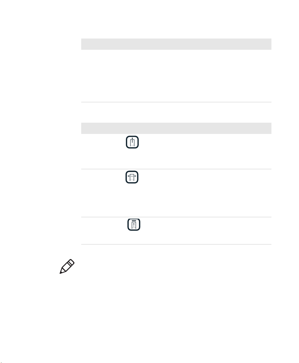
Understanding the Buttons
Name Button Function
Form Feed Press this button to feed the paper into the
Set Page Press this button to signal the beginning of
SET PAGE
Line Feed Press this button to adjust the top of the
press any button and goes off after ten
seconds. The LED also goes on when:
• the printer is attached to an external
power supply
• a print job is sent to the printer
• you perform a power-on-self-test
printer mechanism or when the printer
should advance to the next form. If the
printer runs out of paper, press this button
to initiate automatic paper loading.
the page to the printer after you have made
the appropriate paper adjustments; or to
set the line feed counter to zero and move
the printhead to its home position. Press
this button to clear a Paper Out error so
printing can resume.
paper to the next line.
Note: All printer covers are hinged to the printer. These hinges have a
tension screw (turn clockwise to tighten, turn counterclockwise to
loosen), should you need to adjust them.
4 6820 Series 80-Column Printer User’s Manual
Page 19
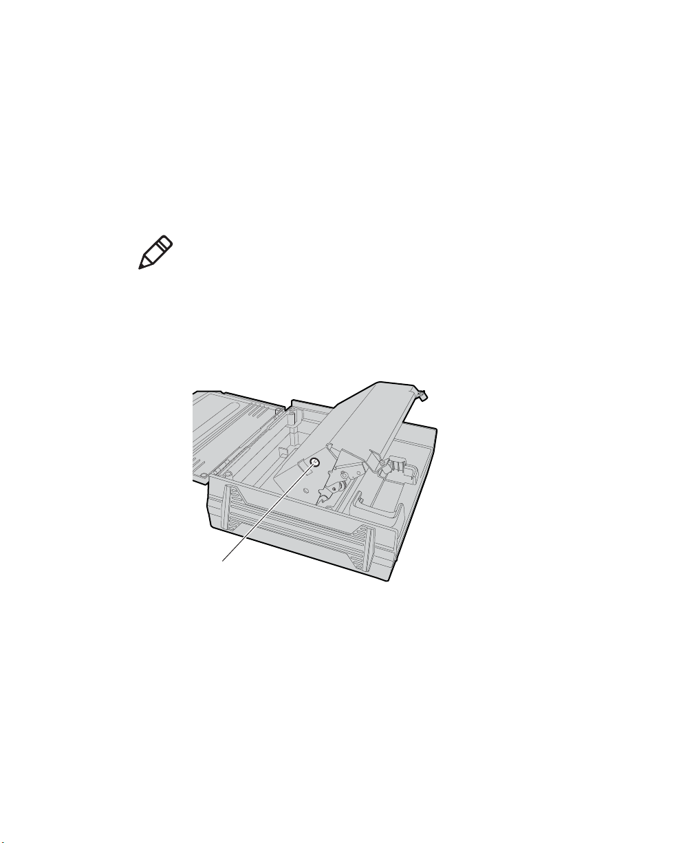
Using the Reset Button
Reset button
Use the printer reset button to:
• reset a printer that is unresponsive and apparently locked up.
• force a synchronization between the printer and a connected PC
when sending control codes.
• restart the printer for any reason.
Note: The reset button does not reset a connected Bluetooth module as
it is powered from a different power source.
Both the fixed mount printer and the portable printer have a reset button
on the left-hand side of the raised printer mechanism. See the following
illustration for the location of the reset button.
Chapter 1 — Using the 6820 80-Column Printer
6820 Series 80-Column Printer User’s Manual 5
Page 20
Chapter 1 — Using the 6820 80-Column Printer
Understanding the Power Supply Options
The following power supply options are available for the 6820.
Using the Internal Battery
The internal battery (P/N 317-075-xxx) allows the portable printer and
some fixed mount printers to operate independently of other power
sources.
The 6820 discharges the internal battery even when the printer is
not is use. Over time, the internal battery can discharge to the point
where the battery is not recoverable.
Plug the printer into an external charge source or disconnect the
battery when you store the printer for any length of time.
A total discharge of the battery is most likely to occur when the battery is
new and the battery chemical reactions are not fully formed, or the
battery has had only one charge cycle.
Connecting to a Vehicle Power Supply
You will need to order a printer installation kit to install the 6820 printer
in a vehicle. The following kits are available:
• P/N 203-242-101 (fixed mount printers)
• P/N 203-242-102 (portable printers)
The installation kits contain all of the hardware (nuts, bolts, washers, a
terminal ring, and a fuse link) for connecting the battery cable directly to
the vehicle battery. These kits also contain adjustable wire clamps to
secure the cable in place.
Note: The 6820 printer and associated electrical wiring should be
installed under the supervision of properly trained and qualified
personnel.
See the 6820 Printer Installation Instructions (P/N 931-052-xxx) to
learn how to connect the printer to a vehicle power supply.
6 6820 Series 80-Column Printer User’s Manual
Page 21
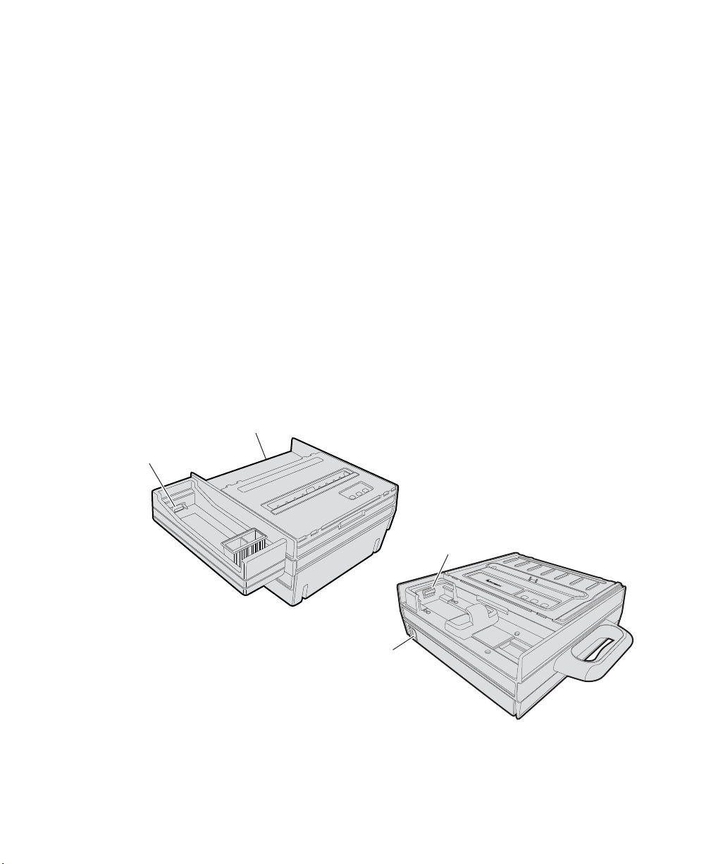
Connecting to a DC Power Source
Fixed Mount Printer
Portable Printer
Mobile computer
socket
Mobile computer
socket
DC power
connector
DC power
connector
Each printer has a DC power jack that connects the printer to a power
source, such as the vehicle battery or an external power supply.
Each printer communicates with a mobile computer through the mobile
computer socket (in a terminal holder, remote terminal holder , or vehicle
dock).
Fixed Mount Printer
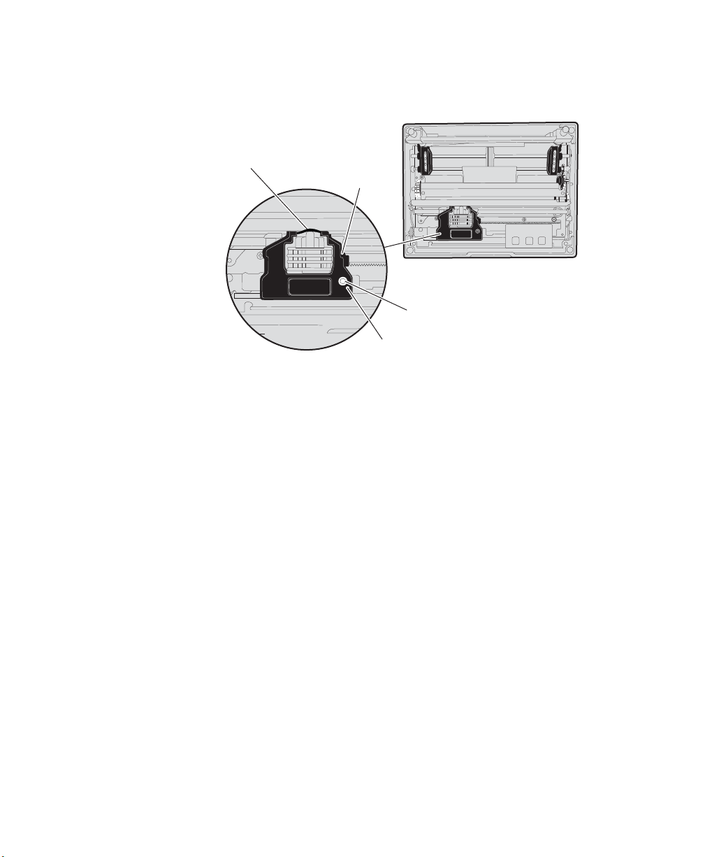
The DC power connector is on the bottom rear of the printer behind the
printer terminal holder. The data communications socket is in either the
printer terminal holder or a separate vehicle dock.
Portable Printer
The DC power connector is on the side of the printer beneath the printer
terminal holder. The data communications socket is either in the printer
terminal holder or a separate vehicle dock.
Chapter 1 — Using the 6820 80-Column Printer
6820 Series 80-Column Printer User’s Manual 7
6820 Printer Models
Page 22

Chapter 1 — Using the 6820 80-Column Printer
8 6820 Series 80-Column Printer User’s Manual
Page 23

2
Installing the 6820 Printer
This chapter provides instructions how to set up the 6820
printer for the first time. In this chapter you will find these
sections:
• Installing the Internal Battery
• Installing the Ribbon Cartridge
• Adjusting the Printhead Gap
• Loading the Paper Tray
• Loading Paper in the Printer
• Inserting a Computer in the Terminal Holder
6822 Series 80-Column Printer User’s Manual 9
Page 24

Chapter 2 — Installing the 6820 Printer
Installing the Internal Battery
The optional internal battery is primarily for portable printers. The
battery can go in some fixed mount printers using a cable and a factoryinstalled adapter.
The printer battery recharges automatically when the printer is
connected to an external power source. For most installations, the
external power source is passed through the printer to the mobile
computer. The printer battery does not provide charge to the computer.
Note: Remove the printer battery when storing a printer for more than 2
or 3 days. After storage, reinstall the battery and connect the printer to
an external power source for at least 14 hours to recharge the battery.
To install the internal battery
1 Unlatch and open the printer mechanism.
2 Lower the battery into the rear of the printer case.
Note: Do not fully seat the battery at this time.
3 Attach the battery cable to the battery.
4 Push the battery down and back under the back edge of the case. The
battery should snap into place.
5 Close and latch the printer mechanism.
10 6822 Series 80-Column Printer User’s Manual
Page 25
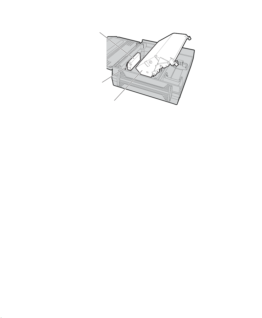
Chapter 2 — Installing the 6820 Printer
Battery
Battery cable
Printer mechanism
Installing the Internal Battery
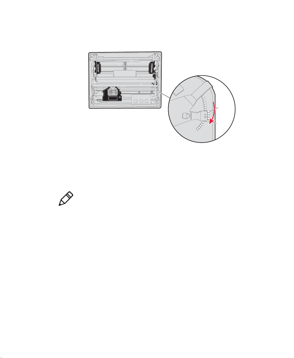
Installing the Ribbon Cartridge
Make sure there is a ribbon cartridge in the printer before you print and
that the ribbon is fully seated (the cartridge makes a distinct “snap” or
“click” when properly seated) with the visible portion of the ribbon
straight and even.
To install the ribbon cartridge
1 Turn the ribbon advance knob (in the direction of the raised arrows)
to remove any slack in the ribbon.
2 Squeeze the ribbon cartridge locking tab into the cartridge, then
lower the cartridge over the printhead.
3 Lower the tab side of the cartridge until it clicks.
4 Release the tab and press down on the arrow to fully seat the ribbon
cartridge (tab clicks outward).
6822 Series 80-Column Printer User’s Manual 11
Page 26
Chapter 2 — Installing the 6820 Printer
Ribbon
Locking
tab
Advance knob
Tighten ribbon
5 Turn the ribbon advance knob (follow raised arrows) to align the
ribbon in the front of the printhead.
Installing the Ribbon Cartridge
Adjusting the Printhead Gap
The printhead gap adjuster is part of the printer mechanism on the side
opposite the green thumb wheel. The printhead adjuster has five notches
between the printhead and the platen for different paper thicknesses.
To adjust the printhead gap
• Verify the thickness of the paper loaded into the printer.
• If you are using single-sheet forms, set the head gap adjuster to the
third notch away from the paper.
• If you are using multiple-sheet forms (2-ply or 3-ply), set the head
gap adjuster to the fourth notch away from the paper.
• If you experience frequent head jams, set the head gap adjuster to the
12 6822 Series 80-Column Printer User’s Manual
fifth notch away from the paper. This may stop the head jams.
Page 27
• If the 2-ply and 3-ply paper have light printing, setting the gap
adjuster to a closer setting will darken the print.
Adjusting the Printhead
Loading the Paper Tray
Chapter 2 — Installing the 6820 Printer
1
5
Note: Do not exceed the recommended paper quantity or thickness.
When loading multiple-sheet paper, be sure to have the original faced
up, with the leading edge towards the rear of the printer.
To load the paper tray in fixed mount and portable printers
1 Unlatch and raise the printer mechanism.
2 Lower a stack of paper, with the original faced up, into the paper tray
under the printer mechanism.
• The fixed mount printer holds up to 200 3-ply forms about 5 cm
(2 in) thick.
• The portable printer holds up to 50 3-ply forms about 2.5 cm (1
in) thick.
3 Pull the top form out and over the rear of the printer mechanism.
4 Lower the printer mechanism back into operating position.
6822 Series 80-Column Printer User’s Manual 13
Page 28

Chapter 2 — Installing the 6820 Printer
To load paper from the flat paper tray
1 Hold a stack of paper, up to 6 cm (2.5 in) thick, with the original
facing you, and lay the stack flat into the tray.
2 Pull the top form out to load into the printer.
Loading Paper in the Printer
Follow these steps to load the paper into the printer, or paper jams
may occur.
Positioning the Paper
Paper for the 6820 has perforated strips that fit onto the pinfeed holder
pins, guiding the paper into the printer. This paper is sold separately in 1,
2, or 3-ply forms.
To position the paper
1 Open the pinfeed holders outward.
2 Take the top edge of the sheet of paper and position it, original side
facing down, over the pinfeed holder pins.
3 Align the first few holes of the paper evenly on each side.
4 Close the pinfeed holders.
14 6822 Series 80-Column Printer User’s Manual
Page 29
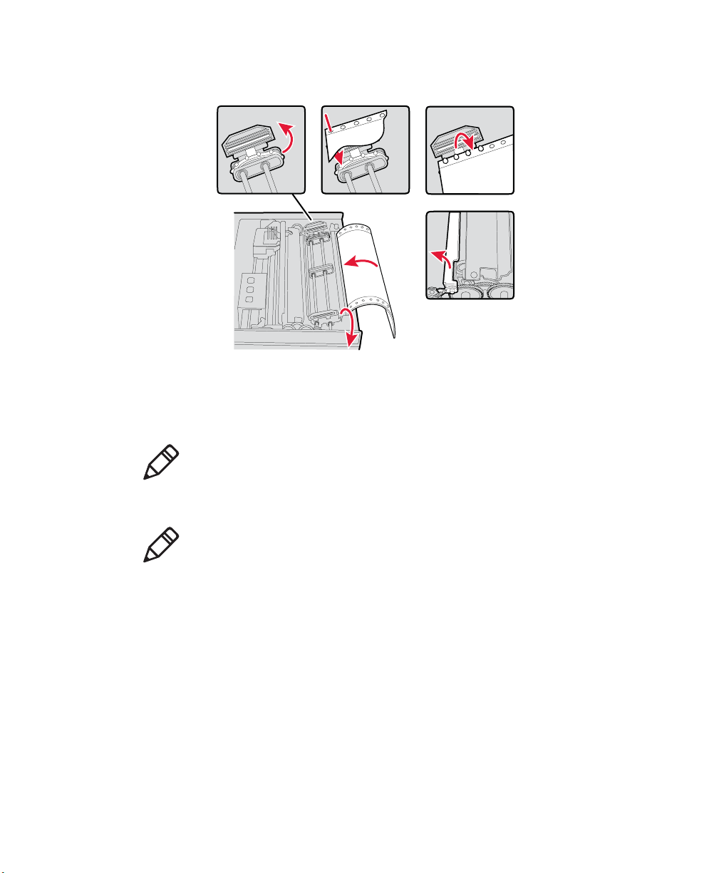
5 Raise the paper bail.
1
2
3
4
5
Positioning the Paper
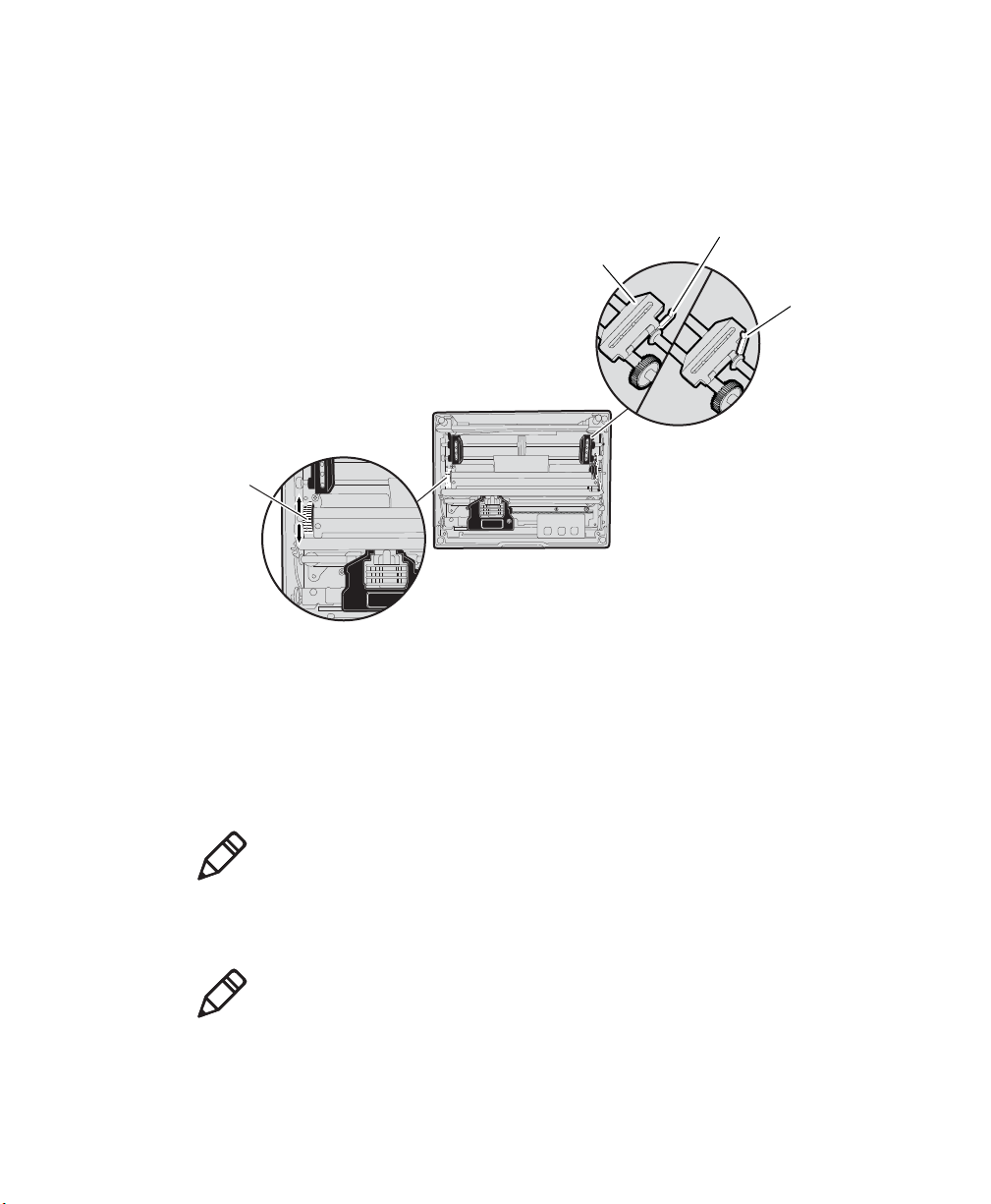
Adjusting the Pinfeed Holders
Note: There are two pinfeed holders, one next to the green thumb wheel
and one opposite the same wheel. Always loosen the pinfeed holder
opposite the green thumb wheel.
Chapter 2 — Installing the 6820 Printer
Note: Adjusting the pinfeed holder next to the green thumb wheel may
cause information to print in the wrong place. If this pinfeed holder is
moved, correct its location by releasing the pinfeed holder tab, moving
the pinfeed holder as close to the green thumb wheel as possible, then
locking the pinfeed holder tab, before adjusting the opposite pinfeed
holder.
To adjust the pinfeed holders
1 With the pinfeed holders open, release the locking tab on the pinfeed
holder opposite the green thumb wheel.
2 Adjust the pinfeed holder position so that the pins align with the
paper.
3 Close the pinfeed holder.
6822 Series 80-Column Printer User’s Manual 15
Page 30
Chapter 2 — Installing the 6820 Printer
4 Ensure that the paper is smooth (no folds, bulges, bows, etc.)
between the pinfeed holders. If so, push the locking tab down on the
pinfeed holder that you adjusted.
Thumbwheel
(green)
Pinfeed
holder
Locked pinfeed
holder locking tab
Released pinfeed
holder locking tab
Adjusting the Pinfeed Holders
To feed paper into the printer
1 Press Form Feed button to feed the paper into the printer.
2 Lower the paper bail. An empty printer auto feeds new paper
approximately 0.25 cm (0.1 in) beyond the top of the paper bail.
Note: The ideal distance to feed paper beyond the paper bail may vary
due to environmental conditions (such as humidity) and specific aspects
of certain paper. Use the green thumb wheel to position the paper to a
desired distance according to your conditions.
Note: If your paper has a preprinted logo on every page, make sure the
printhead is below the preprinted logo. If not, you can adjust the
position of the paper, either by pressing the Lin e Fee d button, or by
using the green thumb wheel.
16 6822 Series 80-Column Printer User’s Manual
Page 31

Chapter 2 — Installing the 6820 Printer
3 Once the paper is properly positioned, press the Set Page button to
clear the Paper Out light and indicate where the top of the page is.
4 Close the printer lid. Make sure the paper passes through the paper
slot when the printer begins to print.
Inserting a Computer in the Terminal Holder
Note: When removing the computer, do not press the computer keys
against the terminal slide retainer. Always store the computer in the
terminal holder.
The fixed mount or portable printers have terminal holder options for the
700 Series, CK60, and the CN3 Series computers.
To insert a 700 Series, CK60, or a CN3 in a terminal holder
1 Insert the top of the computer into the terminal slide retainer.
2 Use the computer to push the terminal slide all the way in the
direction shown.
3 Lower the connector end of the computer into the terminal holder.
4 Slide the computer to fully seat it in the docking connector.
Inserting a Computer in a Terminal Holder
6822 Series 80-Column Printer User’s Manual 17
Page 32

Chapter 2 — Installing the 6820 Printer
18 6822 Series 80-Column Printer User’s Manual
Page 33

3
Configuring the 6820 Printer
Use the Printer Configuration Utility to load fonts on the
printer and to change the printer settings. In this chapter you
will find these sections:
• Connecting to the Printer
• Understanding the Font Modules
• Using the Printer Configuration Utility
• Communicating with the Printer
19
Page 34

Chapter 3 — Configuring the 6820 Printer
Disconnect this terminal holder
ribbon cable from the floor of
the printer cavity
Ignore this cable attached
to the printer mechanism
Connecting to the Printer
Connect your printer to your desktop computer using a serial cable
(P/N 226-270-xxx). The serial COM port connector on either the fixed
mount printer or portable printer is on your printer mechanism, the same
side as the green thumb wheel and next to the reset switch.
Before connecting to your PC, locate and disconnect the gray terminal
holder ribbon cable connector from the floor of the printer cavity. The
cable is located behind the printer mechanism on the same side as the
green thumb wheel and is the one that is not attached to the printer
mechanism.
For information on using the Printer Configuration Utility see page 21.
Understanding the Font Modules
20 6820 Series 80-Column Printer User’s Manual
Intermec provides the following font modules for your 6820:
nft00000.mod — Default International
nft00437.mod — IBM/Microsoft compatible Code Page 437
nft00932.mod — JIS Japanese
nft00936.mod — GB2312 Chinese Simplified
nft00949.mod — KSC5601 Korean
Page 35

Chapter 3 — Configuring the 6820 Printer
• nft00950.mod — Big 5 Traditional Chinese
Note: There are three versions of the default font module
(nft0000.mod): Arabic, Turkish, and International. Any one version of
the default module, but not more than one, can appear in the 6820
Printer Configuration Utility FONTS directory and install on the
printer. The International version of this font module is automatically
placed in the FONTS directory when the Printer Configuration Utility is
installed on the PC.
All three versions are included on the printer toolkit CD:
• The Arabic version is included in the Default Fonts\Arabic directory .
• The Turkish version is in the Default Fonts\Turkish directory.
• The International version is in the Default Fonts\International
directory.
Use the Printer Configuration Utility to replace the existing default font
module (nft00000.mod) with any of the of the other provided fonts. The
Printer Configuration Utility is provided in the 6820 Tool Kit.
Instructions for installing fonts are provided later in this chapter.
If you followed the default installation process, the Printer Configuration
Utility FONTS directory is located at Program Files\Intermec\6820
Printer Configuration Utility\FONTS.
Do not rename the font files in the FONTS dir ectory or they will not
work correctly.
Using the Printer Configuration Utility
These instructions apply to desktop computers running either Windows
2000 or Windows XP operating systems.
Installing the Printer Configuration Utility
The Printer Configuration Utility is provided on the 6820 Printer Toolkit
CD (P/N 235-145-xxx).
6820 Series 80-Column Printer User’s Manual 21
Page 36

Chapter 3 — Configuring the 6820 Printer
To set up your PC to use the Printer Configuration Utility
1 Insert the toolkit CD in your PC.
2 From your desktop, use your Explorer application to view the
contents of the toolkit CD.
3 Double-click the setup.exe file, then click Next from the Welcome
screen to continue.
4 The printer configuration utility files are copied to the Program
Files\Intermec\6820 Printer Configuration Utility folder. To
install the files in a different folder, enter the path and folder name.
22 6820 Series 80-Column Printer User’s Manual
Page 37

Chapter 3 — Configuring the 6820 Printer
You can also specify if everyone who uses the computer has access to
the printer configuration files or limit access to yourself.
5 Click Disk Cost to see the amount of disk space required to install
the Printer Configuration Utility. Click OK to close and return to the
installation screens.
6820 Series 80-Column Printer User’s Manual 23
Page 38

Chapter 3 — Configuring the 6820 Printer
6 Click Next to verify installation, click Back to adjust the information
on the previous screen, or click Cancel to exit the installation.’
7 Installation Complete appears on the screen. Click Close to exit the
installation program.
24 6820 Series 80-Column Printer User’s Manual
Page 39

Chapter 3 — Configuring the 6820 Printer
Disabling the Microsoft ActiveSync Serial Port Connections
If you use Microsoft ActiveSync to connect to your computers, you need
to disable the serial port connections before using the Printer
Configuration Utility.
To disab l e ActiveSync
1 In the ActiveSync application on your desktop, select File >
Connection Settings.
2 Clear Allow USB connections and Allow connections to one of the
following.
3 Click OK.
4 Close the ActiveSync application.
Operating the Printer Configuration Utility
The Printer Configuration Utility consists of a list of fonts, some
parameter settings, and a printer control program.
When the Printer Configuration Utility is active, it holds a
“configuration clipboard” in memory . Initially, this configuration has
parameters set to their default values. Consider the contents of the
configuration clipboard as temporary and lost when you exit from the
utility.
• Click the Get 6820 Configuration button to view the current printer
configuration.
6820 Series 80-Column Printer User’s Manual 25
Page 40

Chapter 3 — Configuring the 6820 Printer
• Click the Set 6820 Configuration button to change printer setting
and send those settings to the printer.
• Click the Reset to Defaults button to reset the to the factory default
printer configuration.
To start the Printer Configuration Utility
• Click the desktop icon or Start > Programs > Intermec > 6820
Printer Configuration Utility > PConfigApp.exe to start the
Printer Configuration Utility.
26 6820 Series 80-Column Printer User’s Manual
Page 41

Communicating with the Printer
Disconnect this terminal holder
ribbon cable from the floor of
the printer cavity
Ignore this cable attached
to the printer mechanism
You can use COM port 1, 2, or 3 to communicate with your printer.
COM port 1 is the default selection, but if it is not available or is being
used by another application, select another COM port.
To communicate with the printer
1 Connect the serial interface cable (P/N 226-270-xxx) from your PC
to the port on the printer mechanism, next to the Reset button
Note: You must also disconnect the terminal holder gray ribbon cable
where it connects to the transition board next to the pivot frame flex
cables.
2 Click either the Get 6820 Configuration or the Set 6820
Configuration button to open communications with the printer.
Chapter 3 — Configuring the 6820 Printer
6820 Series 80-Column Printer User’s Manual 27
The “Opening COM Port x to printer . . . ” message appears in the
text box when you initiate communications with the printer. The “x”
in the message indicates which COM port is being used.
3 When the “Press Reset on the printer” message appears in the text
box, press the Reset button on your printer. For the location of the
Reset button on your printer, see “Using the Reset Button” on
page 5
Page 42

Chapter 3 — Configuring the 6820 Printer
4 The “Opening COM Port x to printer. . . Done.” message indicates
that communication between your PC and the printer has been
established.
Note: If “Unable to open COM Port x to printer” appears in the
text box another software application may be using the selected
COM port. Select another COM port or disable the software
application using the COM port. Also, verify that the gray
terminal holder ribbon is disconnected as indicated earlier. See
page 33 for more error messages.
28 6820 Series 80-Column Printer User’s Manual
Page 43

Chapter 3 — Configuring the 6820 Printer
To view the settings on your 6820
1 Click the Get 6820 Configuration button to initiate communication.
2 The “Getting printer parameters . . . ” message appears when the
Printer Configuration Utility retrieves configuration information
from the printer.
3 The message “Getting printer parameters . . . Done” appears after
configuration information is retrieved.
4 Modify configuration settings or click OK to close the Printer
Configuration Utility.
Setting the 6820 Configuration
Use the Printer Configuration Utility to set or modify the 6820
configuration setting, install or remove fonts, or load an updated printer
control program.
To modify configuration settings
1 Make changes to the Configuration Clipboard or click the Reset to
Defaults button to undo your selections and return them to their
defaults.
Note: When using a Bluetooth adapter you must select the DTR
communications protocol and a bit rate of 19.2 K.
2 Click the Set 6820 Configuration button to initiate communication
with the printer. The “Setting printer parameters . . .” message
appears when you initiate communication with the printer.
3 The “Setting printer parameters . . . Done” message appears when
configuration parameters are set.
Note: The “Unable to set printer parameters” message indicates a
dropped connection between your PC and your printer.
4 If the configuration is complete, click OK to close the utility and
detach the serial cable.
6820 Series 80-Column Printer User’s Manual 29
Page 44

Chapter 3 — Configuring the 6820 Printer
To update 6820 fonts or the 6820 control program
• Click the Fonts and Control button to update the fonts stored in
your printer or to update the printer control program. The Fonts
Available for Update list shows font files that are available. The
Fonts Selected for Update list show fonts that are to be installed on
the printer.
To learn what fonts are currently installed on your printer
• Click the Get Printer Fonts button. The installed fonts appear in the
text box in the bottom right corner of the dialog.
30 6820 Series 80-Column Printer User’s Manual
Page 45

Chapter 3 — Configuring the 6820 Printer
To select a font files
• Highlight the font files you want to download in the Fonts Available
for Update list.
• Click the right arrow pointing to the Fonts Selected for Update list
to copy the selected font files to this list. Below is a sample screen.
If the fonts you select exceed the space available in printer memory, an
error message appears. Click OK to close the error message and not
copy the font to the Fonts Selected for Update list. If there are two or
more fonts that exceed the space allowed, this message repeats until an
error message is displayed for each of the font files that went over the
space allowed.
The Space Needed information shown beneath the Fonts Available for
Update list indicates the total space required (in bytes) for all of the
fonts in the list. The Space Remaining information listed below the
Fonts Selected for Update list displays the space remaining in the
printer, given the fonts in the Selected list.
Click Update Printer to update the printer fonts and the control
program depending on the options selected on the dialog. If the Selected
list is empty and the Include control program update is not checked, a
“Nothing selected for update” message appears in the text box.
• Formats the printer flash for font updates and writes new font files to
the printer for any fonts in the Selected list.
6820 Series 80-Column Printer User’s Manual 31
Page 46

Chapter 3 — Configuring the 6820 Printer
Click the top, right arrow to copy selected font files from the Fonts
Available for Update list to the Fonts Selected for Update list. Click
the bottom, left arrow to remove any selected files from the Fonts
Selected for Update list.
Click Update Printer to update the fonts in the printer with those in the
Fonts Selected for Update list. The Update progress: bar indicates the
progress as the control program or fonts are written to the printer.
• Check the Include program control update check box to include
the printer control program when updating the printer.
Note: You only need to update the contro l program when new versions
of the control program are released.
32 6820 Series 80-Column Printer User’s Manual
Page 47

Default Printer Settings
Default Printer Settings
Settings Value
Zero Print Option Print zeros without a slash
Auto Feed Configuration CR (carriage return at end of line
Protocol NPCP
Parity N/A (for NPCP)
Bit Rate 19.2 K (19200)
For other printer defaults, see “Factory-Installed Printer Defaults” on
page 143.
Error Messages
There are three instances when the 6820 may not connect to your PC. In
the example error messages, an “x” indicates the assigned COM port
number.
Chapter 3 — Configuring the 6820 Printer
without line feed)
Error Messages
Error Type Message Cause
Timeout Error
Unable to open COM port x to
printer. Printer not reset within
the time allowed or printer not
connected to COM port x.
The timeout error may occur due to
either of these situations:
• The printer was not reset in the
time allowed.
• The COM port exists on the
desktop computer but nothing is
connected to the port.
• The gray Bluetooth terminal
holder ribbon cable is not
disconnected from the bottom of
the printer.
Port Not Found
6820 Series 80-Column Printer User’s Manual 33
Unable to open COM port x to
printer. COM port x cannot be
found.
The COM port does not exist. The
particular COM port is identified in
the error message.
Page 48

Chapter 3 — Configuring the 6820 Printer
Error Messages (continued)
Error Type Message Cause
Access Denied
Unable to open COM port x to
printer. Access to COM port x is
denied. Close applications using
COM port x or try another port.
The COM port exists but a
connection with the 6820 is not
established. The particular COM port
is identified in the error message.
Connecting to the Bluetooth Adapter
If your 6820 has a Bluetooth adapter, be sure to connect this adapter after
you finish reconfiguring the 6820 fonts and exit the Printer
Configuration Utility (flat gray ribbon cable under the printer
mechanism).
Enable Microsoft ActiveSync Serial Port Connection
If you use Microsoft ActiveSync to connect to your terminals, then do
the following to enable serial port based connections.
To enable Microsoft ActiveSync serial port based connections
1 Start ActiveSync and select File > Connection Settings.
2 Check Allow USB connections and Allow connections to one of
the following.
3 Click OK.
4 Close the ActiveSync application.
34 6820 Series 80-Column Printer User’s Manual
Page 49

4
Control Code Definitions
This chapter contains a set of control code definitions and
specifications for page layout for the 6820 printer. In this
chapter you will find these sections:
• Understanding Control Code Definitions
• Using Printer Control Codes
• Understanding the Fanfold Paper Page Layout
6820 Series 80-Column Printer User’s Manual 35
Page 50

Chapter 4 — Control Code Definitions
Understanding Control Code Definitions
I/O Buffer
All characters and control codes received by the printer are stored in this
buffer . Characters and controls codes are read from this buffer and acted
upon to form the print buffer. Characters are removed from the I/O
buffer as they are processed.
Print Image Buffer
All characters go through this buffer on their way to the printed page.
This buffer contains the graphic image of the dots to print, from which
characters are rendered. It is cleared when its contents are printed.
Special Notations
The following information defines notations included in the format
definitions of the escape sequences, throughout this section.
Special Notations
Notation Description
(0) Used in the ASCII column of any of the Format definitions, indicates that its value can
only be zero (and not the character “0”). For example: Select Top-Down Printing ESC
US (0).
(1) Used in the ASCII column of any of the Format definitions, indicates that its value can
only be one (and not the character “1”). For example: Select Bottom-Up Printing ESC
US (1).
* When a number (at the end of an escape sequence) is marked with an asterisk, then
either the value corresponding to that number or the value of the string character can be
used for that number. For example, if 1* is shown, then either the value (1), or the value
of the string character (decimal: 49, hex: 31) can be used.
NUL
The NUL character is represented in the Dec column as 0, in the Hex column as 00, and
in the ASCII column as NUL.
36 6820 Series 80-Column Printer User’s Manual
Page 51

Using Printer Control Codes
These control code definitions are organized by categories of functions.
The following methods assist in locating control codes easily:
• Numeric order (single character codes only)—refer to the “Single
Character Control Codes” table on page 138. Locate the index for the
control code, and turn directly to that page.
• Numeric order (complete list)—refer to the “Escape Sequence
Quick Reference” on page 140 and look up control codes by their
actual code values.
Backspace
The print buffer is emptied. The printhead is moved to the left one
character space (using the current pitch). This can be performed to, but
not beyond, the left margin setting. The backspace is ignored if
justification of right, full, or centered is selected.
Format
Decimal Hex ASCII
808 BS
Chapter 4 — Control Code Definitions
The backspace control code (BS) is not reliable when text contains
different character pitches. For reliable backspacing, use the escape
sequence (ESC “\”), Set Relative Print Position.
Beeper
The printer produces a beep lasting approximately 1/10 of a second
Format
Decimal Hex ASCII
707 BEL
6820 Series 80-Column Printer User’s Manual 37
Page 52

Chapter 4 — Control Code Definitions
Cancel Line
All of the characters currently in the print buffer are discarded. Current
print position is set to left margin. Text already printed cannot be
canceled
Format
Decimal Hex ASCII
24 18 CAN
Carriage Return
Repositions the printhead at the start of the print line (usually at the left
margin), and repositions the pointer to the start of the print buffer, after
printing all data in the buffer. Also, all of the “one line” functions are
reset, such as bold, double-strike, double-wide, or unidirectional
printing.
Format
Decimal Hex ASCII
13 0D CR
Note: You can add an automatic line feed with a configuration item.
Delete
Deletes the last character in the print buffer. This functions only in left
justification.
Format
Decimal Hex ASCII
127 7F DEL
38 6820 Series 80-Column Printer User’s Manual
Page 53

Form Feed
Prints the contents of the print buffer, clears the print buffer, and
advances the paper to the top of the next page (Top of Form), according
to the current page length setting. The carriage position is moved to the
start of the line
Format
Decimal Hex ASCII
12 0C FF
Select Half-Speed Printing
Turns on half-speed mode to provide quiet printing, and more accurate
print positioning during text mode printing.
Format
Decimal Hex ASCII
27 115 1* 1B 73 01* ESC “s” 1*
Chapter 4 — Control Code Definitions
Cancel Half-Speed Printing
Turns off half-speed mode (factory default), and continues with normal
speed printing.
Format
Decimal Hex ASCII
27 115 0* 1B 73 00* ESC “s” 0*
6820 Series 80-Column Printer User’s Manual 39
Page 54

Chapter 4 — Control Code Definitions
Set Inactivity Time for Sleep Mode
Sets the amount of time the printer waits before it goes into low-power
mode. The factory default is 10 seconds.
Format
Decimal Hex ASCII
27 122 n 1B 7A n ESC “z” n
Line Feed
Perform Line Feed
Prints and then clears the contents of the print buffer, resets the character
count to zero; and advances the printhead to the next print line, using the
current spacing. The position of the carriage is not affected and a
carriage return is not executed.
Format
Decimal Hex ASCII
10 0A LF
Perform n/216-inch Line Feed
Advances the paper to n/216 of an inch. This does not affect subsequent
line feeds. Range of n is 0-255.
Format
Decimal Hex ASCII
27 74 n 1B 4A n ESC “J” n
40 6820 Series 80-Column Printer User’s Manual
Page 55

Perform n/216-inch Reverse Line Feed
Reverses the line feed by n/216 of an inch. This does not affect
subsequent line feeds. Range of n is 0-255.
Format
Decimal Hex ASCII
27 106 n 1B 6A n ESC “j” n
Perform Master Reset
Initializes the printer and restores factory installed printer defaults, (see
“Factory-Installed Printer Defaults” on page 143 for a complete list
of settings that are initialized with this command).
Format
Decimal Hex ASCII
27 64 1B 40 ESC “@”
Set Print Position (absolute)
Chapter 4 — Control Code Definitions
Moves the printhead to an absolute horizontal position on the paper . The
distance is specified in dots from the left margin to the new print position
(at which subsequent characters are printed). Each dot represents 1/60 of
an inch. The values for n1 and n2 determine the distance, as follows:
number of dots = n1 + (n2 * 256)
Maximum position is 480. The previous contents of the current print
buffer is printed.
If the position specified moves the printhead outside the current margins,
the command is ignored and the previous setting remains in effect. This
command is also ignored in right, center, and full justification modes.
Format
Decimal Hex ASCII
27 36 n1 n2 1B 24 n1 n2 ESC “$” n1 n2
6820 Series 80-Column Printer User’s Manual 41
Page 56

Chapter 4 — Control Code Definitions
Set Print Position (relative)
Moves the printhead to a horizontal position on the paper, relative to the
current printhead position. The distance specified is in dots. To
determine n1 and n2, first calculate the displacement required in
1/120ths of an inch. If the displacement is to the left, subtract it from
65536. The values for n1 and n2 determine the distance, as follows:
number of dots = n1 + (n2 * 256)
Maximum displacement is ±960. If the position specified would place
the printhead outside the current margins, this function is ignored and the
previous setting remains in effect. This function is also ignored in right,
center, and full justification modes.
Format
Decimal Hex ASCII
27 92 n1 n2 1B 5C n1 n2 ESC “\” n1 n2
Select Top-Down Printing
Enables top-down printing (factory default). First page is printed first.
Format
Decimal Hex ASCII
27 31 0 1B 1F 00 ESC US (0)
Select Bottom-Up Printing
Enables bottom-up printing. The last page is printed first.
Format
Decimal Hex ASCII
27 31 1 1B 1F 01 ESC US (1)
42 6820 Series 80-Column Printer User’s Manual
Page 57

Chapter 4 — Control Code Definitions
Select Unidirectional Printing
Turns on unidirectional printing mode. Unidirectional printing moves
the printhead from left-to-right only, allowing for more accurate print
positioning during text mode printing.
Format
Decimal Hex ASCII
27 85 1* 1B 55 01* ESC “U” 1*
Cancel Unidirectional Printing
Turns off unidirectional printing (facto ry default), allowing the printhead
to print in both directions
Format
Decimal Hex ASCII
27 85 0* 1B 55 00) ESC “U” 0*
Select Unidirectional (one line) Printing
Turns on unidirectional printing for the current line only. The contents of
the print buffer is printed, and cleared before setting this mode. This
allows more accurate print positioning during text mode printing, for the
current line.
Format
Decimal Hex ASCII
27 60 1B 3C ESC “<”
6820 Series 80-Column Printer User’s Manual 43
Page 58

Chapter 4 — Control Code Definitions
Page Formatting Functions
This set of functions consists of control codes that change the formatting
of the page. The page length (form length) and margin settings define the
printable area on the page. These settings need to conform to the actual
size of the paper used in the printer. The line spacing functions set the
amount of space from one line to the next, for line feeds. The factory
default is 1/6 inch (6 lines per inch). The page length, vertical tab, and
skip over perforation functions are also dependent on the line spacing
function.
Set Page Length (lines)
Sets the length of the paper in lines, where the range of n (number of
lines) is 1-127 (default = 66). Keep in mind the line spacing and actual
length of the paper when specifying this value, since this function is
dependent on those parameters. Top-of-Form is reset to the current line
and the Skip Over Perforation setting is canceled.
Format
Decimal Hex ASCII
27 67 n 1B 43 n ESC “C” n
Set Page Length (inches)
Sets thee length of the paper in inches, where the range of n (number of
inches) is 1-22 (default = 11). Keep in mind the line spacing and actual
length of the paper when specifying this value, since this function is
dependent on those parameters. Top-of-form is reset to the current line
and the Skip Over Perforation setting is canceled.
Format
Decimal Hex ASCII
27 67 0 n 1B 43 00 n ESC “C” NUL n
44 6820 Series 80-Column Printer User’s Manual
Page 59

Chapter 4 — Control Code Definitions
Select 1/8-inch Line Spacing
Sets the line spacing is set to 1/8 of an inch (8 lines per inch), for
subsequent lines.
Format
Decimal Hex ASCII
27 48 1B 30 ESC “0”
Select 7/72-inch Line Spacing (7 dots)
Sets the line spacing to 7/72 of an inch (approximately 9.7 lines per
inch), for subsequent lines.
Format
Decimal Hex ASCII
27 49 1B 31 ESC “1”
Select 1/6-inch Line Spacing
Sets the line spacing to 1/6 of an inch (6 lines per inch), for subsequent
lines (factory default). 1/6 inch is equal to 12 dot spacing.
Format
Decimal Hex ASCII
27 50 1B 32 ESC “2”
Select n/216-inch Line Spacing
Sets the line spacing to n/216 of an inch, for subsequent lines. A spacing
of 1/216 inch is 1/3 the distance between pins of the printhead
(approximately 1/3 of a dot) and 27/216 is 8 lines per inch. Range of n is
0-255.
Format
Decimal Hex ASCII
27 51 n 1B 33 n ESC “33” n
6820 Series 80-Column Printer User’s Manual 45
Page 60

Chapter 4 — Control Code Definitions
Select n/72-inch Line Spacing (n dots)
Sets the line spacing to n/72 of an inch, for subsequent lines. A spacing
of 1/72 inch (1 point in font size) is the distance between pins on the
printhead (approximately 1 dot) and 9/72 is 8 lines per inch. Range of n
is 0-85.
Format
Decimal Hex ASCII
27 59 n 1B 41 n ESC “A” n
Set Right Margin
Clears all text in the print buffer and sets the right margin to n columns,
using the current character pitch. This is the number of the characters
from column 1 (at the left edge of the paper) to the last column before
the right margin (factory default = 80).
Minimum space between margins is the width of one double-width pica
character. Maximum value for this is the maximum number of characters
(based on the current pitch) that would fit between the left margin and
the right edge of the default printable area of the page. Ranges shown
below could vary, depending on values of other parameters that affect
character width. If the value specified is not within the allowed range, it
is ignored.
Range of n is 2-80 in Pica mode, 2-96 in Elite mode, and 2-13 6 in
compressed mode.
Format
Decimal Hex ASCII
27 81 n 1B 51 n ESC “Q” n
Set Left Margin
Clears the print buffer text and sets the left margin, relative to the
number of columns to the left of the first column to print
(factory default = 0).
46 6820 Series 80-Column Printer User’s Manual
Page 61

Chapter 4 — Control Code Definitions
Minimum space between margins is the width of one double-width pica
character. Maximum value must be less than the right margin. Ranges
shown below could vary, pending on other parameter values that affect
character width. If the specified value is not within the range, it is
ignored.
Range of n is 0-78 in pica mode; 0-93 in elite mode, and 0-133 in
compressed mode.
Format
Decimal Hex ASCII
27 108 n 1B 6C n ESC “l” n
Set Skip Over Perforation
Defines the number of lines to skip between the last printed line on the
page and the first printed line on the next page is set. If the value
specified for this function is greater than the page length, it is ignored.
This function is canceled by using one of the Set Page Length functio ns
(factory default = disabled). This function is valid for continuous paper
only.
The amount of space left blank at the bottom of the printed page is
dependent upon the current Line Spacing.
Format
Decimal Hex ASCII
27 78 n 1B 4E n ESC “N” n
Cancel Skip Over Perforation
Cancels the skip over perforation, which allows the maximum number of
lines to print on each page.
Format
Decimal Hex ASCII
27 79 1B 4F ESC “O”
6820 Series 80-Column Printer User’s Manual 47
Page 62

Chapter 4 — Control Code Definitions
Character Style and Text Mode Functions
The following set of functions affect the appearance of text on the
printed page. This could involve size, typeface, or other characteristics
of the text.
Select Condensed Character Mode
Selects condensed mode which prints characters at approximately 60%
of the normal width. This results in character pitches, as shown below
(for exact pitch values, see “Master Select” on page 53).
Character Pitches
Condensed Mode Condensed + Expanded Condensed + Elite
17 cpi (approximate) 9 cpi (approximate) 20 cpi (approximate)
This function empties the print buffer and turns compressed mode on,
and stays on until canceled by cancel compressed mode, ESC SI or DC2
(factory default = disabled).
Note: This function is not supported in Double-Byte Character Sets
(DBCS).
Format
Decimal Hex ASCII
27 15 1B 0F ESC SI
15 0F SI
Cancel Condensed Character Mode
Cancels the compressed mode, enabled by select compressed mode, SI
or ESC SI (1).
Note: This function is not supported in DBCS.
48 6820 Series 80-Column Printer User’s Manual
Page 63

Chapter 4 — Control Code Definitions
Format
Decimal Hex ASCII
27 18 1B 12 DC2
18 12 DC2
Select Double-Strike Mode
Enables double-strike printing, until cancel double-strike mode is
encountered. Factory default disables double-strike. Text is made bolder
by printing each dot twice, with the second dot slightly below the first
dot. This mode is not available in NLQ, but is not canceled when you
select NLQ.
Note: This function is not supported in DBCS.
Format
Decimal Hex ASCII
27 71 1B 47 ESC “G”
Cancel Double-Strike Mode
Cancels double-strike mode.
Note: This function is not supported in DBCS.
Format
Decimal Hex ASCII
27 72 1B 48 ESC “H”
6820 Series 80-Column Printer User’s Manual 49
Page 64

Chapter 4 — Control Code Definitions
Select Double-Wide Mode
Enables expanded print for the current line only. The mode set
previously returns on subsequent lines. However, expanded print can be
canceled with cancel expanded print, DC4 or ESC “W” (0), before end
of current line, or wrapping of the print buffer. This works with all three
pitches (Pica, Elite, Compressed).
This mode is also terminated by the execution of a Carriage Return, Line
Feed, Form Feed, Vertical Tab or wrapping of the print buffer.
Note: This function is not supported in DBCS.
Format
Decimal Hex ASCII
27 14 1B 0E ESC SO
14 0E SO
Cancel Double-Wide Print
Cancels expanded print for the current line only. Modes set previously
return on subsequent lines. However, it does not cancel expanded mode
set by select double-wide (expanded) mode, ESC “W” (1) or Master
Select, ESC “!”.
Note: This function is not supported in DBCS.
Format
Decimal Hex ASCII
27 20 1B 14 DC4
20 14 DC4
50 6820 Series 80-Column Printer User’s Manual
Page 65

Chapter 4 — Control Code Definitions
Select Double-Wide Print
Enables expanded print until Cancel Expanded Print is encountered.
Factory default disables double-wide mode.
Note: This function is not supported in DBCS.
Format
Decimal Hex ASCII
27 87 1* 1B 57 01* ESC “W” 1*
Cancel Double-Wide Print
Cancels double-wide print mode.
Note: This function is not supported in DBCS.
Format
Decimal Hex ASCII
27 87 0* 1B 57 00* ESC “W” 0
Select Elite Pitch
A character pitch of 12 cpi (characters per inch) is selected. This also
cancels pica pitch (factory default = Pica).
Note: This function is not supported in DBCS.
Format
Decimal Hex ASCII
27 77 1B 4D ESC “M”
6820 Series 80-Column Printer User’s Manual 51
Page 66

Chapter 4 — Control Code Definitions
Select Emphasized Print Mode
Enables emphasized print mode until cancel emphasized mode is
encountered. The text is made bolder by printing each dot twice, with the
second dot slightly to the right of the first dot. Factory default disables
emphasized mode.
Note: This function is not supported in DBCS.
Format
Decimal Hex ASCII
27 69 1B 4B ESC “E”
Cancel Emphasized Print Mode
Cancels emphasized print mode.
Note: This function is not supported in DBCS.
Format
Decimal Hex ASCII
27 70 1B 46 ESC “F”
Define Intercharacter Space
Defines the amount of space to the right of each character, in addition to
the space allowed in the character design. The variable n represents the
number of units of space, with each unit equal to 1/120 of an inch. Range
of values for n is 0-63 with a factory default of 0.
Format
Decimal Hex ASCII
27 32 n 1B 20 n ESC SP n
52 6820 Series 80-Column Printer User’s Manual
Page 67

Chapter 4 — Control Code Definitions
Select Italic Mode
The text (nongraphic) characters are italicized. Factory default disables
italic mode.
Note: This function does not work well with DBCS or alternate Single
Byte Character Sets (SBCS).
Format
Decimal Hex ASCII
27 52 1B 34 ESC “4”
Cancel Italic Mode
Cancels the italic mode.
Note: This function does not work well with DBCS or alternate Single
Byte Character Sets (SBCS).
Format
Decimal Hex ASCII
27 53 1B 35 ESC “5”
Master Select
Allows you to specify a combination of print modes. The variable n is
determined by combining values for the desired modes, by adding them
together.
Note: This function is not supported in DBCS.
Format
Decimal Hex ASCII
27 33 n 1B 21 n ESC “!” n
6820 Series 80-Column Printer User’s Manual 53
Page 68

Chapter 4 — Control Code Definitions
Valid combinations of the values in the following table include any
combinations except that Pica cannot combine with Elite.
Example
Pica Compressed Italic Underlined, by adding values (00h + 04h + 40h +
80h), which results in C4h for the value of n.
Master Select Values
Hex Value Mode
00h Pica
01h Elite
04h Condensed (compressed)
08h Emphasized
10h Double-Strike
20h Double-Width (expanded)
40h Italic
80h Underlined
The following print conflicts occur between modes. A mode in any
column takes precedence over all modes in the columns to its right.
Print Conflicts
1 2 3
Elite Emphasized Compressed
The following print modes can be combined producing different pitches:
Print Modes
Pitch Mode
5 cpi Expanded
6 cpi Expanded Elite
8.58 cpi Expanded Compressed
10 cpi Pica
12 cpi Elite
17.16 cpi Compressed
54 6820 Series 80-Column Printer User’s Manual
Page 69

Chapter 4 — Control Code Definitions
Select Pica Pitch
Select a character pitch of 10 cpi (characters per inch) (factory default).
This also cancels Elite pitch.
Note: This function is not supported in DBCS.
Format
Decimal Hex ASCII
27 60 1B 50 ESC “P”
Select Superscript Mode
Prints all subsequent characters in approximately 2/3 the normal height
in the upper part of the character space, until Cancel Subscript/
Superscript is encountered.
Note: This function is not supported in DBCS.
Format
Decimal Hex ASCII
27 83 0* 1B 53 00* ESC “S” 0*
Select Subscript Mode
Prints all subsequent characters in approximately 2/3 the normal height
in the lower part of the character space, until Cancel Subscript/
Superscript is encountered.
Note: This function is not supported in DBCS.
6820 Series 80-Column Printer User’s Manual 55
Page 70

Chapter 4 — Control Code Definitions
Format
Decimal Hex ASCII
27 83 1* 1B 53 01* ESC “S” 1*
Cancel Subscript/Superscript Mode
Cancels the effects produced by select superscript mode and select
subscript mode. Factory default also disables both of these modes.
Note: This function is not supported in DBCS.
Format
Decimal Hex ASCII
27 84 1B 54 ESC “T”
Select Underline Mode
Enables the underlining of all subsequent characters (including spaces)
until the cancel underline mode function is encountered.
Format
Decimal Hex ASCII
27 45 1* 1B 2D 01* ESC “–” 1*
Cancel Underline Mode
Cancels the effect of the select underline mode. Factory default also
disables the underline mode.
Format
Decimal Hex ASCII
27 45 0* 1B 2D 00* ESC “–” 0*
56 6820 Series 80-Column Printer User’s Manual
Page 71

Tabs and Tab Setting Functions
There are control codes for setting horizontal and vertical tabs.
Horizontal tabs:
• Are not affected by subsequent changes in pitch.
• May range up to maximum width for character and printer size.
• All previous tab stops are cleared when new tab stops are set. If the
left margin is changed after the horizontal tabs are set, tab stops are
cleared.
• Become absolute positions and are not affected by any subsequent
change in character size.
• Set outside of the printable area are ignored.
Vertical tabs:
• Tab positions are line numbers, counting from the Top of Form.
• All tabs set beyond the page length are stored, but are not used.
• Any tab set within the SOP range (Skip Over Perforation), during the
time SOP is active, are stored but not used until SOP is canceled.
Chapter 4 — Control Code Definitions
• If a vertical tab, and the next tab stop is outside the printable page
area, a form feed is executed placing the printhead at the next Top of
Form.
• Previous tab stops are cleared when new tab stops are set.
• Are not affected by subsequent changes in line spacing.
Perform Horizontal Tab
Moves the print position to the next horizontal tab stop. The tab
positions, set by ESC “D”, the Set Horizontal Tabs function, are not
affected by any changes in character pitch.
The factory default tab settings are at intervals of eight characters, in the
currently selected pitch. For the default tabs, the actual distance to each
tab position is affected by changes in character pitch.
Format
Decimal Hex ASCII
909 HT
6820 Series 80-Column Printer User’s Manual 57
Page 72

Chapter 4 — Control Code Definitions
Set Horizontal Tabs
Resets the current horizontal tabs, and new horizontal tabs are set up,
based on the current character width (pitch).
Format
Decimal Hex ASCII
27 68 n1 n2 ..nk 0 1B 44 n1 n2 .. nk 00 ESC “D” n1 n2 .. nk NUL
n1 is the first tab (range for tab stops: 1-160), n2 is the second tab (all
tabs in ascending order), ... are subsequent tabs (maximum tabs: 32), nk
is the last tab to set (any value less than the previous tab value acts as a
terminating character), NUL is the terminating character.
Clear Horizontal Tabs
Clears all horizontal tab stops. It is merely a variant behavior of the Set
Horizontal Tabs function, where the NUL acts as an early terminating
character, as existing tabs normally clear before setting any new tabs.
Format
Decimal Hex ASCII
27 68 0 1B 44 00 ESC “D” NUL
Perform Vertical Tab
Prints the contents of the current print buffer, and then moves the print
position to the next vertical tab stop. If no channel is selected, then
channel 0 is used. The carriage position is changed to the start of the next
print line. If the vertical tab is performed beyond the last tab position set
or beyond the last line of a form, then a form feed is performed. If no
vertical tabs are defined, then the paper advances one line, using the
currently selected line spacing, without changing the carriage position.
Format
Decimal Hex ASCII
11 0B VT
58 6820 Series 80-Column Printer User’s Manual
Page 73

Chapter 4 — Control Code Definitions
Set Vertical Tabs
Resets the current tabs, and vertical tabs are set up, based on the current
line spacing. Tab settings are not affected by subsequent changes in line
spacing.
Format
Decimal Hex ASCII
27 66 n1 n2 .. nk 0 1B 42 n1 n2 .. nk 00 ESC “B” n1 n2 .. nk NUL
n1 is the first tab (range of values for tab stops: 1-255), n2 is the second
tab (all tabs must be in ascending order), ... are subsequent tabs
(maximum number of tabs: 16), nk is the last tab to set (any value less
than the previous tab value acts as a terminating character), NUL is the
terminating character. All tab settings with this function are stored in
channel 0.
Clear Vertical Tabs
Clears all vertical tab stops. This is a variant behavior of the Set Vertical
Tabs function, where the NUL acts as an early terminating character.
Format
Decimal Hex ASCII
27 66 0 1B 42 00 ESC “B” NUL
Set Vertical Tabs in Channel
This function works the same as the Set Vertical Tabs function, except
that it stores the tabs into a specified channel, as specified by the
variable c. This channel is selected for use by the Select Vertical Tab
Channel function.
Format
Decimal Hex ASCII
27 98 c n1 n2 .. nk 0 1B 62 c n1 n2 .. nk 00 ESC “b” c n1 n2 .. nk NUL
6820 Series 80-Column Printer User’s Manual 59
Page 74

Chapter 4 — Control Code Definitions
c is the channel number (range: 0-7), n1 is the first tab (range of values
for tab stops: 1-255), n2 is the second tab (all tabs must be in ascending
order), ... are subsequent tabs (maximum number of tabs is 16), nk is the
last tab to set (any value less than the previous tab value acts as a
terminating character), and NUL is the terminating character.
Clear Vertical Tabs in Channel
Clears all vertical tab stops in the specified channel. This is a variant
behavior of the Set Vertical Tabs in Channel function, where the NUL
acts as an early terminating character, since this function normally clears
the existing tabs before setting any new tabs.
Format
Decimal Hex ASCII
27 98 c 0 1B 62 c 00 ESC “b” c NUL
Select Vertical Tab Channel
Selects a specified vertical tab channel. It sets up the current tabs from
that channel. Once this function is performed, all subsequent Perform
Vertical T ab commands use the tab stops from the list retrieved from the
specified channel. At power on, the printer uses the tabs stored in
channel 0.
Format
Decimal Hex ASCII
27 47 c 1B 2F c ESC “/” c
c is the channel number (range: 0-7).
Using Character Sets and User-Defined Functions
You can install different character sets on the printer . In some cases more
than one character set may be present at one time, depending on the
amount of available font memory. The 6820 reserves 438 K of memory
for installing fonts in flash memory . You can install fonts using NPCP or
the Printer Configuration Utility.
60 6820 Series 80-Column Printer User’s Manual
Page 75

Chapter 4 — Control Code Definitions
Single-Byte Character Sets
Single-byte character sets (SBCS) are supported for MS-DOS, PL/N,
and Intermec application compatibility. Nft00000.mod is the default
character set (font) for compatibility with the 6820 Nft00437.mod is the
IBM/Microsoft compatible character set for Code Page 437.
Double-Byte Character Sets
Double-byte character (DBCS) sets require two bytes to send to the
printer to define the character to print. The first byte of the character
code sent to the printer is known as a lead-in byte. The second byte of
the character code is known as the trailing byte. Different character sets
have different requirements for the values of both lead-in and trailing
byte. When the lead-in byte does not fall in the range listed for the
character set, a character from a SBCS may print. The following
double-byte character sets are supported by the 6820.
Double-Byte Character Sets
Code
Font Module
nft00936.mod 936 GB 2312 Chinese
nft00950.mod 950 big 5 Traditional
nft00932.mod 932 Shift JIS Japanese 81h–9Fh
nft00949.mod 949 KSC 5601 Korean A1h–ACh
Page
DBCS Languages Lead-in Byte Trailing Byte
A1h–ABh
(simplified)
Chinese
B0h–F7h
A1h–C6h
C9h–F9h
E0h–FCh
B0h–C8h
CAh–FDh
A1h–FEh
40h–FEh (except 7Fh)
40h–FCh (except 7Fh)
A1h–FEh
Multi-Byte Character Sets
Double-byte character sets and single-byte character sets can mix when
printing a report. This mixture is referred to as a Multi-Byte Character
Set (MBCS). When a DBCS is selected, the characters from the SBCS
code page currently selected are used for rendering character codes and
control codes from 0 to 127. Codes above 127 (that fall within the range
of lead-in bytes for the selected character set) treat the byte that follows
as a trailing byte for that character set. Otherwise, for character codes
6820 Series 80-Column Printer User’s Manual 61
Page 76

Chapter 4 — Control Code Definitions
above 128, the character code from the selected SBCS is printed.
NFT00950.MOD (BIG 5 DBCS) does not allow the MBCS mode. For
this character set, only control codes from 0-31 are treated as single byte
characters when they are not proceeded by a lead-in byte. All escape
sequence character strings are treated as SBCS.
Select National Character Set
By default, code page 0 is selected by the printer at reset. Use the
following escape sequence to select international character support.
Escape sequence codes can only be used for code page 0. All other code
pages use direct character code mapping to select the appropriate font for
rendering.
Format
Decimal Hex ASCII
27 82 n 1B 52 n ESC “R” n
n is 0-14 and is the country code, as shown in the International Character
Sets table on the next page. The default value for n is zero (USA).
A full 256 character set is not provided for these sets. There are 64
international characters stored in ROM, 32 in Roman and 32 in Italic.
They are stored as codes 0-31 and 128-255. These are normally not
accessible. The ESC
“R” command makes these codes available, but
only 12 characters at a time. These 12 are available in these positions of
the ASCII character table: 35, 36, 64, 91, 92, 93, 94, 96, 123, 124, 125,
and 126, as shown in the International Character Sets table.
International Character Sets
Country
USA 0 #$@[\]^‘{|}~
France 1 #$ຠç§^‘éùè¨
Germany 2 # $ § ÄÖÜ^ ‘ ä ö ü b
England (UK) 3 £ $ @ [ \ ] ^ ‘ { | } ~
Denmark 1 4 #$@ÆØÅ^‘æøå~
Sweden 5 # ¤ ЙДЦЕЬй д Це ь
Italy 6 #$@º\ é^ùà èì
62 6820 Series 80-Column Printer User’s Manual
Country
Number
35 36 64 91 92 93 94 96 123 124 125 126
Page 77

International Character Sets (continued)
Chapter 4 — Control Code Definitions
Country
Spain 1 7 P$@¡Ñ¿^‘¨ñ}~
Japan 8 #$@[¥]^‘{|}~
Norway 9 # ¤ ЙЖШЕЬй жш е ь
Denmark 2 10 # $ ЙЖШЕЬй жш е ь
Spain 2 11 #$á¡ Ñ¿é‘ í ñóú
Latin America 12 # $ á ¡ Ñ ¿ é ü í ñ ó ú
Hebrew 13 Hebrew fonts are available in the supplied font files. See “Hebrew
Greece 14 Greek fonts are available in the supplied font files. See the “Greek
Country
Number
35 36 64 91 92 93 94 96 123 124 125 126
Character Fonts” below.
Character Set” on page 64.
Hebrew Character Set
Hebrew characters represented by decimal values 38 and 65 through 90
are represented by the following 7x7 font descriptions.
*.*.*.. ....*.* *.*.*.* *.*.*.* ....*.* *.*.*.* *.*.*.* *..*.*.
....*.. ......* .....*. .....*. ......* ...*... .*...*. *..*..*
....*.. ....*.* .....*. *....*. ......* ...*... *....*. *..*..*
....*.. ...*..* .....*. *....*. ......* ...*... *....*. *.....*
*.*.*.* ..*...* .....*. *....*. ......* ...*... *....*. *....*.
....... ....... ....... ....... ....... ....... ....... *.*.*..
....... ....... ....... ....... ....... ....... ....... .......
65 66 67 68 69 70 71 72
....... ....... ....... *...... ....... ....... ....... .......
....*.* ..*.*.* *.*.*.. *.*.*.* *.*.*.* *..*... ....*.* ....*.*
......* ......* ......* ......* *.....* .*.*.*. ......* ......*
......* ......* ......* .....*. *.....* ..*...* ......* ......*
....... ......* ......* ....*.. *.....* .*....* ......* ......*
....... ......* *.*.*.. .*.*... *.*.*.* *...*.* ......* ..*.*.*
....... ....... ....... ....... ....... ....... ....... .......
....... ....... ....... ....... ....... ....... ....... .......
73 74 75 76 77 78 79 80
....... ....... ....... ....... ....... ....... ....... .......
*.*.*.* *.....* *.*.*.* *.*.*.. *....*. *.....* *.*.*.* *.*.*.*
..*...* *.....* *.....* *.....* .*..*.. .*...*. ......* ......*
.*....* .*...*. *.*...* *.*...* ..*.*.. ...*... .*....* ......*
*....*. ..*.*.. ......* ......* ......* .....*. *.*.*.* ......*
6820 Series 80-Column Printer User’s Manual 63
Page 78

Chapter 4 — Control Code Definitions
*.*.*.. *.*.*.* ......* *.*.*.. ......* *.*.*.* *...... ......*
....... ....... ......* ....... ......* ....... *...... .......
....... ....... ....... ....... ....... ....... ....... .......
81 82 83 84 85 86 87 88
.....*. ....... .......
*..*..* ..*.*.* *.....*
*..*..* ..*...* .*....*
*..*..* ..*...* .*.*.*.
*.*..*. ..*...* *....*.
*...*.. *.*...* *.....*
....... ....... .......
....... ....... .......
89 90 91
Greek Character Set
Greek Character Set
Dec Hex Chr Dec Hex Chr Dec Hex Chr
97 61 A 105 69 I 113 71 P
98 62 B 106 6a K 114 72 S
99 63 G 107 6b L 115 73 T
100 64 D 108 6c M 116 74 Y
101 65 E 109 6d N 117 75 F
102 66 Z 110 6e X 118 76 X
103 67 H 111 6f O 119 77 Y
10468 q 11270 P 12078 W
The selected set stays in effect until the printer is reset and receives a
Master Reset command, or a new international character set is selected.
Note: This function is only used with the default character set
64 6820 Series 80-Column Printer User’s Manual
Page 79

User Defined Characters
This section describes user-defined characters and how characters are
copied into printer memory.
Note: RAM-based definition or redefinition of standard characters is
only useful when the default SBCS code page is selected. There is no
method to redefine characters in the other code pages, since unique
code pages can be created and loaded into the printer memory.
Copy ROM to RAM
The characters in ROM are copied into RAM, so a complete
user-defined character set is created by editing selected characters. This
ensures that all characters are defined when a user-defined character set
is selected. This eliminates the need to cancel th e selection when printing
defined characters.
Note: This function is only useful with the default SBCS.
Format
Chapter 4 — Control Code Definitions
Decimal Hex ASCII
27 58 0 0 0 1B 3A 00 00 00 ESC “.” NUL NUL NUL
Define User Defined Characters
Characters are redefined by the user in the currently selected mode.
However, they can only be used in draft mode.
Note: This function is only useful with the default SBCS.
Format
Decimal Hex ASCII
27 38 0 k1 k2 s1
d1 ... d11
6820 Series 80-Column Printer User’s Manual 65
1B 26 00 k1 k2 s1
d1 ... d11
ESC “&” k1 k2 s1
d1.....d11
Page 80

Chapter 4 — Control Code Definitions
k1 is the character code of the first character to redefine, k2 is the
character code of the last character to redefine (any character between
0-255 can be redefined), and (k1 could equal k2, if only one character is
defined).
For each character defined, you must supply 12 bytes of data.
• s1 is the first byte that describes the character format
• Bits 0-3 represent the end position in the grid
• Bits 4-6 represent the start position in the grid
• Bit 7 determines whether the character uses the top eight pins or the
bottom eight pins of the printhead. If bit 7 = 0, the top eight pins are
used. If bit 7 = 1, the bottom eight pins are used. The start and end
positions are ignored during character imaging, but must be accurate
to redefine the character code. d1...d11 is the da ta that comprises the
dot image pattern of the defined character.
When printable code expansion is enabled with ESC I, the Printable
Code Area Expansion function, and the user-defined character set is
selected with ESC “%” (1), the Select User-Defined Set function, then
the codes (less than 20h and greater than 7Fh) can be defined for use and
are printable.
When printable code expansion is enabled with the Enable Printing of
Codes 128-159 function, and the user-defined character set is selected
with the Select User-Defined Set function, then codes (between 80h and
9Fh) can be defined for use and are printable.
For a list of these characters, refer to the “Printable Code Expansion
Characters” on page 68.
Select User-Defined Character Set
A user-defined character set can be selected, after the Define
User-Defined Characters function is used to define the character set.
Note: This function is only useful with the default SBCS.
66 6820 Series 80-Column Printer User’s Manual
Page 81

Chapter 4 — Control Code Definitions
Format
Decimal Hex ASCII
27 37 1 1B 25 01 ESC “%” (1)
Select Default Character Set
If the Select User-Defined Set function was previously set, this function
switches back to the default character set.
Note: This function is only useful with the default SBCS.
Format
Decimal Hex ASCII
27 37 0 1B 25 00 ESC “%” (0)
Enable Printing of Codes 128-159
All codes (128-159) are treated as printable characters, rather than
control codes, with this function. This allows the use of these characters
for user-defined characters. A user-defined set must be selected, using
the Select User-Defined Set function, before these characters can print.
Factory default disables printing of these codes.
Note: This function is only useful with the default SBCS.
Format
Decimal Hex ASCII
27 54 1B 36 ESC “6”
6820 Series 80-Column Printer User’s Manual 67
Page 82

Chapter 4 — Control Code Definitions
Disable Printing of Codes 128-159
Disables the printing of codes 128-159. By default, these codes are
disabled.
Format
Decimal Hex ASCII
27 55 1B 37 ESC “7”
Expand Printable Code Area
This function allows certain ASCII codes (00h to 1Fh) and codes (80h to
9Fh) to print when the variable n is set to the value of 1. This allows the
use of these codes for user-defined characters. If n = 0, the function
returns these two ranges of characters to non-printable control codes. A
user-defined character set must be selected by ESC “%” (1), the Enable
Printing of Codes 128-159 function, before these codes can print. In both
ranges, only the following codes can redefine as printable characters.
Codes not listed, within the range (00h-1Fh), print as standard control
codes. Codes not listed, within the range (80h-9Fh), are converted to a
control code in the range of (00h-1Fh), by subtraction of 80h.
Note: This function is only useful with the default SBCS.
Format
Decimal Hex ASCII
27 73 n 1B 49 n ESC “I” n
Printable Code Expansion Characters
Hex ASCII Hex ASCII Hex ASCII Hex ASCII
00 NUL 11 DC1 80 none 91 none
01 SOH 15 NAK 81 none 95 none
02 STX 16 SYN 82 none 96 none
03 ETX 17 ETB 83 none 97 none
04 EOT 1C FS 84 none 9C none
68 6820 Series 80-Column Printer User’s Manual
Page 83

Chapter 4 — Control Code Definitions
Printable Code Expansion Characters (continued)
Hex ASCII Hex ASCII Hex ASCII Hex ASCII
05 ENQ 1D GS 85 none 9D none
06 ACK 1E RS 86 none 9E none
10 DLE 1F US 90 none 9F none
Enable Printing of Character Graphics
Enables the printing of character graphics, until disabled with the
Disable Printing of Character Graphics function.
Note: This function is only useful with the default SBCS.
Format
Decimal Hex ASCII
27 116 1 1B 74 01 ESC “t” (1)
For character values from 0 to 31 (00h-1Fh):
• When the default SBCS code page is selected, the FX-86e IBM
character graphics symbol set is printed.
• When other SBCS code pages are selected, the codes (00h-1Fh),
listed above in the Printable Code Expansion Characters table are
printed.
For character values from 32 to 126 (20h-7Eh):
• When the default SBCS code page is selected, the selected
international character set is printed.
• When other SBCS code pages are selected, the international
character set selection is not in effect.
For the character value 127 (7Fh):
• When the default SBCS code page is selected, a space is printed
• When other SBCS code pages are selected, the character associated
with the code page is printed.
6820 Series 80-Column Printer User’s Manual 69
Page 84

Chapter 4 — Control Code Definitions
For character values from 128 to 255 (80h-FFh), the FX-86e Epson
Character Graphics set is printed.
Disable Printing of Character Graphics
Disables the printing of character graphics. Factory default disables this
function.
Format
Decimal Hex ASCII
27 116 0 1B 74 00 ESC “t” (0)
Enable Printing of Character Graphics
This function allows printing of character graphics from the currently
selected SBCS code page, by sending a graphics string to t he printer . The
values of the graphics data bytes can range between 0-255.
Format
Decimal Hex ASCII
27 43 n d1 ... dn 1B 2B n d1 ... dn ESC “+” n d1 ... dn
n is the length of the character graphic string and d1 ... dn are the
character graphics data stream.
The number of data bytes must be equal to the value of the variable n.
The range of values (for the characters in each graphics data byte):
0-255.
For character values from 0 to 31 (00h-1Fh):
• When the default SBCS code page is selected, the FX-86e IBM
character graphics symbol set is printed.
• When other SBCS code pages are selected, currently selected single
byte code page character graphics are printed.
For character values from 32 to 126 (20h-7Eh):
• When the default SBCS code page is selected, the selected
international character set is printed.
70 6820 Series 80-Column Printer User’s Manual
Page 85

• When other SBCS code pages are selected, the character from the
currently selected code page are printed.
For the character value 127 (7Fh):
• When the default SBCS code page is selected, a space is printed
• When other SBCS code pages are selected, the character graphics
symbol is printed.
For character values from 128 to 255 (80h-FFh):
• When the default SBCS code page is selected, the FX-86e Epson
Character Graphics set is printed.
• When other SBCS code pages are selected, the corresponding
character is printed.
Graphics Functions
Eight-Pin Graphics Modes
All 8-pin graphics functions require parameters, n1 and n2, which
represent the length of the graphics string that follows the select graphics
mode command, and are calculated as follows (assuming a temporary
variable n):
Chapter 4 — Control Code Definitions
• n = total number of graphics dots needed for the graphic string
• n2 = integer of (n divided by 256)
• n1 = remainder of the n2 calculation
The simplest calculation, is to divide n (total number of dots needed for
the graphics string) by 256. Then n2 is the quotient (the whole number)
and n1 is the remainder . If you require less than 256 do ts (columns), then
n1 indicates the number of dots and n2 is set to zero.
6820 Series 80-Column Printer User’s Manual 71
Page 86

Chapter 4 — Control Code Definitions
Select Graphics Mode
Enables the graphics mode represented by the variable m in the Graphic
Modes table. The total number of dot columns to print is represented by
n1 and n2. Any graphic string that exceeds the length of the print line is
discarded.
Format
Decimal Hex ASCII
27 42 m n1 n2 1B 2A m n1 n2 ESC “*” m n1 n2
Reassign Graphics Mode
Changes graphic modes.
Format
Decimal Hex ASCII
27 63 s n 1B 3F s n ESC “?” s n
s is one of the K, I, Y, or Z characters and n is one of the 0-7 modes as
shown in Graphic Modes table.
Graphic Modes
Mode n Dots per Inch / Dots per 8 in Line
Single-dDensity 0 60 dots per inch, 480 dots per 8 in line
Low Speed Double-Density 1 120 dots per inch, 960 dots per 8 in line
*High Speed Double-Density 2 120 dots per inch, 920 dots per 8 in line
*Low-Speed Quadruple-Density 3 240 dots per inch, 1920 dots per 8 in line
CRT I 4 60 dots per inch, 480 dots per 8 in line
Single–Density Plotter 5 72 dots per inch, 576 dots per 8 in line
CRT II 6 90 dots per inch, 720 dots per 8 in line
*Double-Density Plotter 7 144 dots per inch, 1152 dots per 8 in line
*Adjacent dots in a given row cannot be printed in these modes.
72 6820 Series 80-Column Printer User’s Manual
Page 87

Chapter 4 — Control Code Definitions
Select Single Density Graphics Mode
This is a simple method of printing graphics. The resolution is 60 dots
per inch. Each 8-inch line can accommodate 480 columns of graphic
dots. A graphic string that exceeds the length of the print line is
discarded. Calculating the parameters, n1 and n2, is described on
page 74.
Format
Decimal Hex ASCII
27 75 n1 n2 1B 4B n1 n2 ESC “K” n1 n2
Select Low-Speed Double Density Graphics Mode
If Single Density graphics does not produce high enough density, try this
mode. The number of dots per inch is doubled. However, the speed is
reduced to half of what it would be with single density. Calculating the
parameters, n1 and n2, is described in “Nine-Pin Graphics Modes” on
page 74.
This is 8-pin single density graphics. The resolution is now 120 dots per
inch. Each 8-inch line can accommodate 960 columns of graphic dots. A
graphic string that exceeds the length of the print line is discarded.
Format
Decimal Hex ASCII
27 76 n1 n2 1B 4C n1 n2 ESC “L” n1 n2
Select High-Speed Double Density Graphics Mode
This 8-pin graphics mode produces the same density as the Low-Speed
Double Density mode, however, the speed is doubled. Calculating the
parameters, n1 and n2, is described on page 74.
Format
Decimal Hex ASCII
27 89 n1 n2 1B 59 n1 n2 ESC “Y” n1 n2
6820 Series 80-Column Printer User’s Manual 73
Page 88

Chapter 4 — Control Code Definitions
The resolution is still 120 dots per inch. Each 8-in line can accommodate
960 columns of graphic dots. A graphic string that exceeds the length of
the print line is discarded. Make sure adjacent dots in a given dot row are
not printed.
Select Low-Speed Quadruple Density Graphics Mode
With this 8-pin graphics mode, the number of dots per inch has gone up
to 4x what it was in single density. Calculating the parameters, n1 and
n2, is described below.
Format
Decimal Hex ASCII
27 90 n1 n2 1B 5A n1 n2 ESC “Z” n1 n2
The resolution is now 240 dots per inch. Each 8-in line can
accommodate 1920 columns of graphic dots. A graphic string that
exceeds the length of the print line is discarded. Make sure adjacent dots
in a given dot row are not printed.
Nine-Pin Graphics Modes
These 9-pin graphics functions also require two parameters, n1 and n2.
They are calculated slightly different than in the 8-pin graphics modes.
Since two data bytes represent each dot column to print, first divide the
total length of the graphic string (following the Select Graphics Mode
command) by two. These parameters are calculated as follows (assuming
a temporary variable n):
• n = total number of dots needed, divided by 2
• n2 = integer of (n divided by 256)
• n1 = remainder of the n2 calculation
First, divide n (the total number of dots needed for the graphics string)
by 2, then divide the result by 256. Then n2 is the quotient (the whole
number) and n1 is the remainder. If you require less than 256 dots
(columns), then n1 indicates the number of dots and n2 is set to zero.
74 6820 Series 80-Column Printer User’s Manual
Page 89

Chapter 4 — Control Code Definitions
Select 9-Pin Single Density Graphics Mode
Enables single density 9-pin graphics mode. Calculating the parameters,
n1 and n2, are described previously under nine-pin graphics modes.
Format
Decimal Hex ASCII
27 94 0 n1 n2 1B 5E 00 n1 n2 ESC “^” (0) n1 n2
The resolution is 60 dots per inch. Each 8-in line can accommoda te 480
columns of graphic dots. A graphic string that exceeds the length of the
print line is discarded.
Select 9-Pin Double Density Graphics Mode
Enables double density, 9-pin graphics mode. The parameters, n1 and
n2, are described previously under 9-pin graphics modes
Format
Decimal Hex ASCII
27 94 1 n1 n2 1B 5E 01 n1 n2 ESC “^” (1) n1 n2
The resolution is now 120 dots per inch. Each 8-inch line can
accommodate 960 columns of graphic dots. A graphic string that
exceeds the length of the print line is discarded.
6820 Series 80-Column Printer User’s Manual 75
Page 90

Chapter 4 — Control Code Definitions
76 6820 Series 80-Column Printer User’s Manual
Page 91

5
Troubleshooting and
Maintaining the 6820
This chapter helps you correct printing problems that may
occur. If you experience a printing problem, you can perform
several tests to find and possibly correct the problem. In this
chapter you will find these sections:
• Troubleshooting Basics
• Aligning the Printer Mechanism
• Understanding Printer Errors
• Troubleshooting Using the Printer Self-Test
• Understanding Diagnostic Information
• Cleaning the Printer Case
• Cleaning the Printer Ribbon
• Cleaning the Mask Spring
6820 Series 80-Column Printer User’s Manual 77
Page 92

Chapter 5 — Troubleshooting and Maintaining the 6820
Troubleshooting Basics
The printing system is composed of four basic components: power
source, printer, computer, and communications. Any one of these
components can prevent the printer from functioning properly.
Checking the Power Source
Press any button on the printer control panel. If there is power, the power
indicator (green LED) turns on and the printhead moves to its starting
position. If the printer emits beeps and any of the other indicators light
up or flash, observe the number of beeps and indicator flashes and see
“Printer Failure Indicators” on page 82.
If there is no reaction from the printer after you press a button on the
control panel, or if the power LED blinks, verify that the power cables
are properly connected between the printer mechanism and its power
source (internal battery, vehicle cable, or ac). If none of these steps
“wake” up the printer with the problem, then you need to return the
printer for service.
• Internal battery
Check the battery and its cable by installing into a known-good
printer.
• Vehicle cable
Attach the printer in question to another vehicle power cable or
another printer to the vehicle cable you are using.
• AC power
Plug the printer into another outlet.
Testing the Printer
If the power indicator works properly and the printer still does not print,
then printer errors are noted. If any indicators light when you press the
Set Page button, or the printer beeps, refer to the Printer Failure
Indicators table on page 82 to determine the problem.
78 6820 Series 80-Column Printer User’s Manual
Page 93

Chapter 5 — Troubleshooting and Maintaining the 6820
If none of the listed conditions are indicated by the beep codes and
LEDs, yet the printer does not perform properly, then perform a printer
self-test. Press and hold (for several seconds) both Form Feed and the
Set Page buttons at the same time, until the printer beeps and all
indicator lights come on. The lights change throughout the test, as it
progresses.
At the end of the self-test, the printer generates a report. This report
verifies the following:
• errors detected during self-test
• error history
• communication configuration
If the printer self-test report does not print, reset the printer. If the report
does print after resetting, then the printer is all right and the reason the
printer does not respond to PC print requests is probably
communications or PC related. If the report is partially completed, and a
printer error occurs during the printing of self-test, see the Printer Failure
Indicators table on page 82 for the cause of the printer failure.
Perform a power-on-self-test (POST) to test for errors either by resetting
the printer or powering it up. If errors occur, audible error codes, along
with indicator light status, are produced during POST (see the POST
Error Codes table on page 83).
If the POST completes without error, try the printer self-test again. If the
self-test prints correctly, but the printer does not respond to the PC, then
the problem may be related to communications or PC problems.
Testing Communications/PC
Use the self-test report to verify that the communications protocol
options, selected at the printer, match those expected by the host. For
information on the self-test report see “Running the Self-Test” on
page 86. If communication protocol options are incorrect, reconfigure
the printer as described in “Setting the 6820 Configuration” on
page 29.
6820 Series 80-Column Printer User’s Manual 79
Page 94

Chapter 5 — Troubleshooting and Maintaining the 6820
3 Top left
2 Bottom
left
1 Top right
4 Bottom
right
Aligning the Printer Mechanism
If head jams occur, you may need to align the printer mechanism.
To align the printer mechanism
1 Open the printer top cover, then install a ribbon cartridge (see
page 15) and position the printhead to the far left toward the green
thumb wheel.
Pivot frame
2 Check the area between the printhead and the printer cavity. If the
ribbon cartridge touches the pivot frame, the printer mechanism
needs realignment.
3 Loosen the four screws that hold the mechanism in place using a
Phillips screwdriver.
80 6820 Series 80-Column Printer User’s Manual
Page 95

Chapter 5 — Troubleshooting and Maintaining the 6820
4 Push the printer mechanism to the right away from the green thumb
wheel.
5 Press on the right side of the printer mechanism to the back as far as
it will go.
Note: In this position, the right back edge of the printer
mechanism may touch the pivot frame. The left side must
not touch the pivot frame.
6 Hold the printer mechanism in place and tighten the screws in the
sequence shown below.
Understanding Printer Errors
Printer errors are divided into classes:
• Runtime errors
• Power-On-Self-Test (POST) errors
• Fatal errors (consisting of flash write errors and EEPROM block
errors)
Runtime Errors
Runtime errors can occur during the course of printing. These errors are
displayed on the LEDs, along with beep sequences. This causes the
printer to stop printing and enter an error state. Then beep sequences are
emitted, LED codes are displayed, the error status may be sent to the
host (depending on the protocol), and the printer goes into suspend
mode.
The printer exits from the suspend mode when the user presses one of
the keyboard keys or communications is resumed from the host. The
printer also places the printhead in its home position and attempts to
recover from the error condition. Until the error condition is corrected,
the error procedure does not end, and the error state is not removed.
6820 Series 80-Column Printer User’s Manual 81
Page 96

Chapter 5 — Troubleshooting and Maintaining the 6820
For paper out errors, load paper and press the Set Page button before
printing begins. Press the Form Feed button to load the paper to the top
of form. The following table provides a listing of printer failure
indicators and describes what they mean.
Printer Failure Indicators
Sets of Beeps Paper Out Head Jam Low Batt Meaning
1 beep Off Off On 12 V under voltage fault (Low
Battery)
1 set of 2 beeps Off Off 2 blinks 12 V over voltage fault (Input
Voltage too high)
1 set of 3 beeps Off Off 3 blinks 24 V under voltage fault (internal
power supply failure)
1 set of 4 beeps Off Off 4 blinks 24 V over voltage fault (internal
power supply failure)
1 set of 13 beeps Off Off Off Configuration error
2 sets of 2 beeps Off 2 blinks 2 blinks printhead over temperature
2 sets of 3 beeps On Off Off Paper Out
2 sets of 4 beeps Off On Off Head Jam
5 sets of 2 beeps 5 blinks 5 blinks 5 bli nks Paper feed current fault
(Possible paper jam or feed motor
failure)
3 sets of 2 beeps 3 blinks Off 3 blinks printhead over current (printhead
failure)
3 sets of 4 beeps Off 3 bli nks Off Home switch failure
4 sets of 2 beeps 4 blinks 4 blinks Off printhead short (printhead failure)
12 sets of 12 beeps Off Off Off Operating System software failure
Note: The most common errors are Paper Out, Low Battery, and Head
Jam. Status indicators on the front panel alert you to these errors. For a
description see “Understanding the Status Indicators” on page 3.
82 6820 Series 80-Column Printer User’s Manual
Page 97

Chapter 5 — Troubleshooting and Maintaining the 6820
Troubleshooting Using the Power-On-Self-Test (POST)
When you reset the printer, a POST runs to determine why the printer
might be failing. Audible error codes, along with indicator light status,
are produced during POST if an error occurs. See on POST Error Codes
on page 83.
To perform a POST
1 Open the printer case.
2 Insert the printer diagnostic cable into the phone jack on the printer
and then connect the 9-pin D-sub plug to your PC. The cable is used
during POST to configure the printer, access printer diagnostics,
update software, and install new fonts.
3 Press the Reset button to start the POST. When the POST starts, the
power LED will come on followed by a single beep indicating that
the printer is active.
Note: After the test is completed, all LEDs turn off and the
printhead moves to the home position. Only runtime errors or
fatal errors are reported until the next time the printer is reset
and POST is performed.
The printer emits beeps and flashes the LEDs to indicate the cause of any
POST errors. POST error codes are described in the following table.
POST Error Codes
Long
Beep
0 1 Off Off Off On Operational
0 0 Off Off Off Off No Power
0 0 Off Off Off On Control program Initial Program Load (IPL)
1 1 Off On Off On Invalid CRC on boot block
1 2 Off On On On Invalid CRC on control program or program not
1 4 Off Off Off On Upper 192K RAM failure
1 4 Off Off On On Upper 64K RAM failure
0 0 On Off Off On D iagnostic mode command check
6820 Series 80-Column Printer User’s Manual 83
Short
Beep
Paper
Out
Head
Jam
Low
Batt
Power Meaning
successful
found
Page 98

Chapter 5 — Troubleshooting and Maintaining the 6820
POST Error Codes (continued)
Long
Beep
1 5 On Off On On Diagnostic flash memory check failed or is not
1 5 On On Off On Diagnostic memory write failure
0 0 On On On On Control program IPL
Short
Beep
Paper
Out
Head
Jam
Low
Batt
Power Meaning
initialized
Understanding Fatal Errors
There are two types of fatal errors, flash write errors and EEPROM
configuration block errors. These errors are extremely rare, but measures
are built into the printer diagnostics to track possible occurrences.
Flash Write Errors
Errors related to writing or erasing flash are critical errors. These errors
cause the printer to stop all processing and produce an LED code and a
sequence of beeps. The LED code indicates the address of the segment
where the error occurred in octal notation.
The octal digit changes every four beeps until four octal digits are
output. Only four octal digits are output since blocks are 256 bytes in
size and flash can be addressed with a total of 0x7ff blocks. The segment
address output is the runtime address of the flash block and not the offset
of the block within flash.
To obtain the block offset within the flash
• Subtract 0x800 from the address output to determine the block offset.
The printer suspends after the processing the error code. When the
printer resumes, an error again and the printer suspends again. Reset the
printer to correct the error. If a reset does not correct the error, have the
printer checked by a qualified service technician.
Note: Flash write errors may be unrecoverable.
84 6820 Series 80-Column Printer User’s Manual
Page 99

Chapter 5 — Troubleshooting and Maintaining the 6820
EEPROM Configuration Block Errors
Errors related to an invalid block (diagnostic block) produce 13 beeps,
and then the printer suspends. It continues to produce this symptom until
the configuration block error is corrected.
Configuration block errors may be caused by a flash write error or an
incorrect printer configuration. Reset the printer to correct the error. If a
reset does not correct the error, try reloading the printer control program
using the Printer Configuration Utility or have the printer checked by a
qualified service technician.
Troubleshooting Using the Printer Self-Test
Self Test Function Descriptions
The self-test performs the following functions.
Boot Block Program Verification
A CRC (Cyclic Redundancy Check) is performed on the boot block
program. The calculated CRC is compared to the CRC embedded in the
program module.
Control Program Ver i fication
A CRC is performed on the control program, which is loaded into
writable flash program memory . The calculated CRC is compared to the
CRC embedded in the program module. The results of this test are
printed on the self-test report.
Font Module Verification
A CRC is performed on the font modules, which are loaded into writable
flash font memory. The calculated CRC is compared to the CRC
embedded in the program module. Results are printed on the self-test
report.
A2D Check
Current reading of the A2D sources are performed, and the results are
printed on the self-test report.
Nonvolatile Diagnostic Memory Verification
A CRC is performed on the area of the nonvolatile diagnostic memory
that has a CRC over it. Results are printed on the self-test report.
6820 Series 80-Column Printer User’s Manual 85
Page 100

Chapter 5 — Troubleshooting and Maintaining the 6820
Nonvolatile Diagnostic Memory Update
The nonvolatile diagnostic memory is updated from the nonvolatile
diagnostic memory data shadowed in memory.
Performing a Printer Self-Test
Initiating a Self-Test
• While the printer is idle or in Suspend mode, press the Line Feed and
Set Page buttons simultaneously to start a self-test.
Terminating Self-Test
• Press the Line Feed and Set Page buttons simultaneously to
manually terminate a self-test.
Running the Self-Test
Perform a self-test to verify printer functions, and provide reporting of
printer diagnostics. The self-test performs a series of internal diagnostics
and prints the results. When the self-test begins, the beeper sounds for
half a second and all LEDs turn on for half a second.
A self-test is equivalent to a warm start. Both are performed when you
simultaneously press Form Feed and Set Page buttons on the control
panel for a few seconds. Release the buttons when the printer beeps and
all indicators are lit. If you press the buttons for too long, the self-test
will not happen and the printer will form-feed one page.
As the self-test progresses, the indicator lights change. Internal tests are
performed and a two page report is printed. The report provides helpful
information in diagnosing and troubleshooting printer problems.
Understanding the Self-Test Report
The self-test report is divided into sections. Refer to page 89 and
page 90 for a sample printout. All other values are informational only.
Remember that these values are cleared after the self-test.
• The printer model number is given on line 1 (first line). This
identifies the printer type used, in this case the 6820.
• The 8-digit serial number of the printer is listed on line 4 under the
“Serial#” heading on line 3. The serial number is also on the inside of
86 6820 Series 80-Column Printer User’s Manual
 Loading...