

Page 1

Part No. 067871-001
Coax/Twinax Interface Card Service Technician
Instructions
The coax/twinax interface card is an internal interface card for Intermec 3XXX, 44XX,
501XP, and 601XP printers. This instruction explains how to install the interface and
how to set the DIP switches and jumper. This instruction sheet has seven sections:
Preparing a 3XXX or 44XX Printer This section explains how to open the 3XXX and
44XX printers.
Preparing a 501XP or 601XP Printer This section explains how to open the 501XP
and 601XP printers.
Installing the Coax/Twinax Interface Card This section explains how to install the
interface card and connect it to the PCB of the 3XXX, 44XX, 501XP, or 601XP
printer.
Testing the Interface Card This section explains how to test to make sure the interface
card is communicating with the printer and host.
Jumper and DIP Switch Settings This section describes the different jumper and DIP
switch settings.
Making the Coax/Twinax Interface Card Backward-Compatible This section explains
how to set the jumper and DIP switches if you are replacing an old twinax card (Part
No. 057029-004) or an old coax card (Part No. 057026-004).
Setting the Coax/Twinax Interface Card to Use IBM Latin 1 This section explains how
to set the jumper and DIP switches to use IBM Latin 1.
Note: The illustrations for the 3XXX and 44XX printers show a 4420 and the
illustrations for the 501XP and 601XP printers show a 501XP.
You will need the following to install the interface card:
• One of the following field installation kits:
• Twinax kit for the 3XXX and 44XX printers, Part No. 067879
• Twinax kit for the 501XP and 601XP printers, Part No. 067881
• Coax kit for the 3XXX and 44XX printers, Part No. 067880
• Coax kit for the 501XP and 601XP printers, Part No. 067882
• A Phillips screwdriver (3XXX and 44XX printers)
• A torx wrench (501XP and 601XP printers)
1
Page 2

Coax/Twinax Interface Card Service Technician Instructions
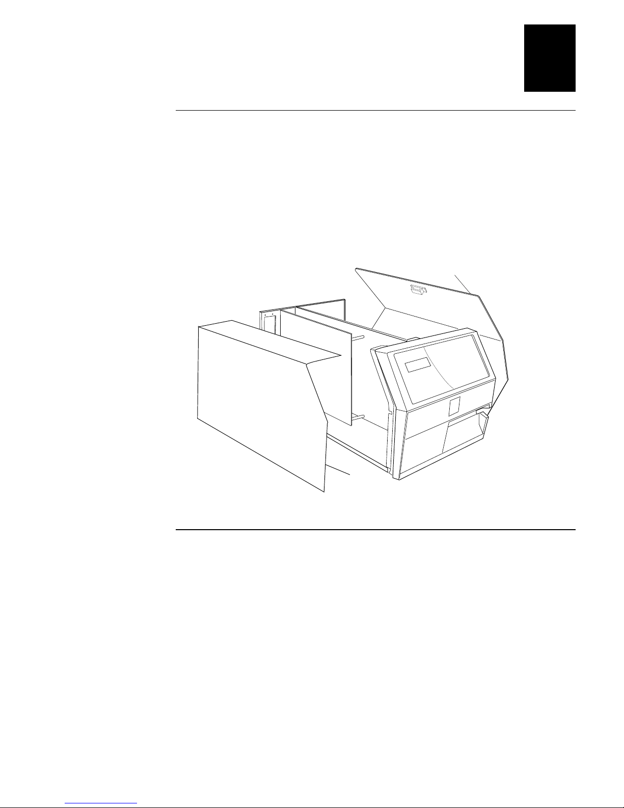
Preparing a 3XXX or 44XX Printer
1. Turn off the printer and remove the AC power cord from the printer.
2. Pull the bottom of the media cover away from the base of the printer, lift the front
of the media cover upward to release it from the printer frame, and lift the media
cover away from the top of the printer.
3. Take out the three screws securing the PCB cover to the main deck and the three
screws securing the PCB cover to the base of the printer.
4. Pull the bottom of the PCB cover away from the base of the printer, slide the top of
the PCB cover away from the main deck, and lift the PCB cover away from the
printer.
J23
Cutter
Media
cover
COAXTWINI .004
PCB
cover
2
Page 3
Preparing a 501XP or 601XP Printer
Preparing a 501XP or 601XP Printer
1. Turn off the printer and remove the AC power cord from the printer.
2. Pull the top of the media cover out and down from the printer.
3. Take out the four screws securing the PCB cover to the main deck and the four
screws securing the PCB cover to the base of the printer.
4. Pull the bottom of the PCB cover away from the base of the printer, slide the top of
the PCB cover away from the main deck, and lift the PCB cover away from the
printer.
Media
cover
PCB
cover
COAXTWINI.003
Installing the Coax/Twinax Interface Card
1. Remove the plate covering the coax/twinax interface card expansion slot on the
back panel of the printer.
2. Set the DIP switches and jumpers for the card. For help, see “Jumper and DIP
Switch Settings” later in this instruction sheet.
3. Mount the coax/twinax interface card to the inside back panel of the printer.
4. For the 501XP or 601XP printer, remove and disconnect the current parallel card if
one is installed.
5. Attach the coax/twinax connector to the parallel port (J3 port or P31 port).
6. Reinstall the PCB and media covers.
7. Attach the coax or twinax adapter cable to the 9-pin connector on the interface
card.
3
Page 4

Coax/Twinax Interface Card Service Technician Instructions
Installing the Coax/Twinax Interface Card in a 3XXX or 44XX Printer
Back
panel
Plate
Screw
(2 places)
Coax/twinax
interface card
J3
J23
Cutter
Coax/twinax
connector
Installing the Coax/Twinax Interface Card in a 501XP or 601XP Printer
Screw
(4 places)
Plate
Coax/twinax
interface card
Coax/twinax
connector
Back
panel
P31
port
COAXTWINI.002
4
COAXTWINI.001
Page 5

Testing the Interface Card
Testing the Interface Card
Note: For the following test to work properly, you must first complete the procedure
under “Installing the Coax/Twinax Card.”
1. Turn off the printer, set the interface card rotary switch to position 7 (perform
self-test), and then turn on the printer. The printer prints the interface card self-test
label.
2. Turn off the printer, set the interface card rotary switch to position 0 (set twinax
cable address), and then turn on the printer.
3. Turn off the printer, set the interface card rotary switch to position A (normal
operation), and then turn on the printer. The interface card and the printer are now
ready to communicate with the host system.
Jumper and DIP Switch Settings
This section provides the definitions for the jumper and DIP switch settings on the
coax/twinax interface card.
Jumper Settings
By opening or closing jumper 1, you can select the label format.
Jumper 1: Output Label Format
Setting Format
Open With DIP switch 2, selects either Roman 8 (DIP switch 2 off) or Code Page 850
(DIP switch 2 on). Open is the default setting for the 501XP and 601XP printers.
Closed With DIP switch 2, selects either Intermec-compatible Latin 1 (DIP switch 2 off)
or IBM Latin 1 (DIP switch 2 on). Closed is the default setting for the 3XXX and
44XX printers.
Note: Use Intermec-compatible Latin 1 only when replacing the Intermec twinax card,
Part No. 057029-004, or the Intermec coax card, Part No. 057026-004, with the
coax/twinax interface card.
DIP Switch Settings
The printer reads the DIP switches when you turn on the printer and set the output port
and factory default settings. The factory default settings are listed in the following
table:
Card Default settings
Coax Intermec-compatible Latin 1 with multinational character set or Roman 8 with
U.S.A./Canada character set and Coax Buffer 1920
Twinax Intermec-compatible Latin 1 with multinational character set or Roman 8 with
U.S.A./Canada character set and 5256M1 Printer ID
5
Page 6

Coax/Twinax Interface Card Service Technician Instructions
If you use a software package or download the commands listed in Chapters 2 and 3 of
the Coax/Twinax Interface Card User’s Manual (Part No. 067867) to change the
printer settings, the software settings or commands will overwrite the DIP switch
settings. All of the parameters that can be set by DIP switch can also be set by the
commands listed in Chapters 2 and 3 of the user’s manual except for the commands to
set the country character set (coax command 08 and twinax command 05). To use these
commands to set the country character set, you must set DIP switch 2 to the on position.
DIP Switch 1: Active Output Port Selection
Setting Port
Off XP printer port and Centronics
On Standard printer port (Intermec custom port)
DIP Switch 2: Code Page Selection
Setting Page
Off Intermec-compatible Latin 1 with jumper 1 closed
Roman 8 with jumper 1 open (default)
On IBM Latin 1 with jumper 1 closed
Code Page 850 with jumper 1 open
DIP Switches 3 and 4: Printer ID (Twinax) and Coax Buffer Size (Coax)
Switch 3 Switch 4 Printer ID Coax Buffer Size
Off Off 5256 (default) 1920 (default)
Off On 5224 3440
On Off 5225 960
On On 4214 3564
6
Page 7

Jumper and DIP Switch Settings
DIP Switches 5 through 8: Host Default Country Character Set
Note: The code page used for each language is in brackets [ ] .
Switch 5 Switch 6 Switch 7 Switch 8 Twinax Coax
Off Off Off Off 1-U.S.A./Can. [037] 1-U.S.A./Can. [037]
Off Off Off On 2-Austria/
Germany [273]
Off Off On Off 3-Belgium [274] 3-Austria/
Off Off On On 4-Brazil [275] 4-Belgium [274]
Off On Off Off 5-Canada/
France [276]
Off On Off On 6-Denmark/
Norway [277]
Off On On Off 7-Finland/
Sweden [278]
Off On On On 8-France [297] 8-Denmark/
On Off Off Off 9-Italy [280] 9-Finland/
On Off Off On 10-Japan [281] 10-Finland/
On Off On Off 11-Japan/
England [037]
On Off On On 12-Portugal [282] 12-France alt. [297]
2-U.S.A./Can.
(alternate [alt.]) [037]
Germany [273]
5-Brazil [275]
6-Canada/
France [276]
7-Denmark/
Norway [277]
Norway (alt.) [287]
Sweden [278]
Sweden (alt.) [288]
11-France [297]
On On Off Off 13-Spain [284] 13-Austria/
On On Off On 14-Latin America
On On On Off 15-United Kingdom
On On On On 00-Multinational
[284]
[285]
[500]
Germany (alt.) [286]
14-Multinational
[500]
15-Italy [280]
16-Japan/
England [037]
7
Page 8

Coax/Twinax Interface Card Service Technician Instructions
Making the Coax/Twinax Interface Card
Backward-Compatible
This section describes how to return the interface card to the factory default setting,
which is backward-compatible with the Intermec twinax card (Part No. 057029-004)
and the Intermec coax card (Part No. 057026-004). These older cards used a modified
version of the Latin 1 code page (referred to as Intermec-compatible Latin 1) to
translate ASCII data to EBCDIC data. If you have created label formats for these older
cards and then installed the new interface, the following procedure will set the interface
card so that your existing label formats will work.
Note: If installing the interface card instead of replacing an older card, select IBM
Latin 1 or Code Page 850 as the code page for the interface card. These code pages
match the way IBM translates its character sets.
To emulate the Intermec twinax card (Part No. 057029-004)
1. Set the DIP switches and jumpers to the following settings:
Switch/Jumper Position Comment
DIP switch 1 On Intermec custom port
DIP switch 2 Off Intermec-compatible Latin 1
DIP switches 3 and 4 Off Printer ID 5256
Jumper 1 Closed Intermec label format
2. Set the rotary switch to position 8 and turn on the printer. The interface card will
reset to the DIP switch and jumper settings and the printer will print the
configuration label. The configuration label will have the following information:
INTERMEC Twinax Adapter
1998 SDE
Software REV X.X
Address 0
Emulation 5256
Host Language INTERMEC
Control Code Parse = Yes
Character Set = INTERMEC
ROM OK RAM OK
3. Keep the configuration label and turn off the printer.
4. Use the rotary switch to set the address and turn on the printer.
5. Turn off the printer, set the rotary switch to position A, and turn on the printer.
6. If you want to use a language character set other than multinational, set the IBM
language translation and the printer language selection to the language you want.
For help, see the user’s manual for the printer that the interface card is installed in.
8
Page 9

Setting the Coax/Twinax Interface Card to Use IBM Latin 1
To emulate the Intermec coax card (Part No. 057026-004)
1. Set the DIP switches and jumpers to the following settings:
Switch/Jumper Position Comment
DIP switch 1 On Intermec custom port
DIP switch 2 Off Intermec code page
DIP switches 3 and 4 Off Printer ID 5256
Jumper 1 Closed Intermec label format
2. Set the rotary switch to position 8 and turn on the printer. The interface card will
reset to the DIP switch and jumper settings and the printer will print the
configuration label. The configuration label will have the following information:
INTERMEC Coax Adapter
1998 SDE
Software REV X.X
Emulation 5256
Host Language INTERMEC
IR Timeout = 120 * 5 secs.
Control Code Parse = Yes
Character Set = INTERMEC
ROM OK RAM OK
3. Keep the configuration label and turn off the printer.
4. Turn off the printer, set the rotary switch to position A, and turn on the printer.
5. If you want to use a language character set other than multinational, set the IBM
language translation and the printer language selection to the language you want.
For help, see the user’s manual for the printer that the interface card is installed in.
Setting the Coax/Twinax Interface Card to Use IBM Latin 1
To set the coax/twinax interface card for the IBM Latin 1 code page, you must
• set jumper 1 to closed.
• set DIP switch 1 to the on position.
• set DIP switch 2 to the on position.
Use this setting when you set the host default country character set on the interface
card. If you set the country character set on the interface card, do not enable IBM
translation or select the language on the printer.
9
Page 10

6001 36th Avenue West
P.O. Box 4280
Everett, WA 98203-9280
© 1998 Intermec
All Rights Reserved
P/N 067871-001
 Loading...