

Page 1

6620 Hand-Held Computer
TECHNICAL
REFERENCE
" " " " " " " " " " " " " " " " " " " " " " " " " " " "
P/N: 977-054-007
Revision B
June 1999
Page 2

" NOTICE The information contained herein is proprietary and is provided solely for the
purpose of allowing customers to operate and service Intermec manufactured
equipment and is not to be released, reproduced, or used for any other purpose
without written permission of Intermec.
Disclaimer of Warranties. The sample source code included in this document is
presented for reference only. The code does not necessarily represent complete,
tested programs. The code is provided “AS IS WITH ALL FAULTS.” ALL
WARRANTIES ARE EXPRESSLY DISCLAIMED, INCLUDING THE
IMPLIED WARRANTIES OF MERCHANTABILITY AND FITNESS FOR A
PARTICULAR PURPOSE.
Wewelcome your comments concerning this publication. Although every effort has
been made to keep it free of errors, some may occur. When reporting a specific
problem, please describe it briefly and include the book title and part number,as
well as the paragraph or figure number and the page number.
Send your comments to:
Intermec Technologies Corporation
Publications Department
550 Second Street SE
Cedar Rapids, IA 52401
INTERMEC, NORAND, NOR*WARE, and PEN*KEY are registered trademarks
of Intermec Technologies Corporation.
Ó 1998 Intermec Technologies Corporation. All rights reserved.
This publication printed on recycled paper.
Acknowledgments
AS/400, IBM, IBM PC, Micro Channel, PS/2, and OS/2 are registered
trademarks and AIX and Presentation Manager are trademarks of International
Business Machines Corporation.
Ericsson is a registered trademark of Telefonaktiebolaget LM Ericsson.
Microclean II is a registered trademark of Foresight International.
Microsoft, MS-DOS, and Windows, are registered trademarks and Visual Basic for
Windows,and Windows for Pen are trademarks of Microsoft Corporation.
PenRight! and PenRight! Pro are trademarks of PenRight Corporation.
SanDisk is a trademark of SanDisk Corporation.
Turbo Pascal is a registered trademark and Borland C and C++ for Windows are
trademarks of Borland International, Inc.
Page 3

FCC Computer Compliance
"
NOTICE This equipment meets Class B digital device limits per Part 15 of FCC Rules.
These limits protect against interference in a residential area. It emits, uses, and
can radiate radio frequency energy. If you do not install and use the equipment
according to its instructions, it may interfere with radio signals. However, there is
no guarantee that interference will not occur in a particular installation.
If this equipment does cause harmful interference to radio or television reception,
which can be determined by turning our equipment off and on, the user is
encouraged to try to correct the interference by one or more of the following
measures:
" Reorient or relocate the radio or television receiving antenna.
" Increase the separation between the computer equipment and receiver.
" Connect the equipment into an outlet on a circuit different from that to
which the radio or television receiver is connected.
" Consult the dealer or an experienced radio or television technician for
help.
Canadian Computer Compliance
This Class B digital apparatus meets all requirements of the Canadian
Interference-Causing Equipment Regulations.
Cet appareil numérique de la classe B respecte toutes les exigences du Reglèment
sur le material boilleur du Canada.
Canadian 2.4 GHz Radio License
"
NOTICE This device requires a radio license, unless it is installed totally inside a building.
(Users must obtain this license.)
Une licence radio est requise pour ces dispositifs, sauf pour ceux installés tout à
fait à l’intérieur d’un bâtiment. (Il faut que l’utilisateur obtienne cette licence.)
Page 4

Telephone Installation Warning Notices
The following notices apply to equipment that may be connected to telephone lines
or systems. For your personal safety, and to protect this equipment from potential
electrical or physical damage, do NOT connect equipment to telephone lines or
data communication equipment unless the following warnings have been read,
understood, and complied with.
" Never install telephone wiring during a lightning storm.
" Never install telephone jacks in wet locations unless the jack is
specifically designed for wet locations.
" Never touch uninsulated telephone wires or terminals unless the
telephone line has been disconnected at the network interface.
" Use caution when installing or modifying telephone lines.
" Avoidusing a telephone (other than cordless type) during an electrical
storm. There may be a remote risk of electric shock from lightning.
" Do not use the telephone to report a gas leak in the vicinity of the leak.
Installation du téléphone : avertissements
Les avertissements qui suivent s’appliquent à tout équipement qui peut être
branché aux lignes ou systèmes téléphoniques. Pour votre sécurité personnelle et
pour protéger l’équipement de tout dommage électrique ou physique potentiel, NE
PASbrancher un ordinateur tablette électronique ou ses périphériques aux lignes
téléphoniques ou équipements avant que les avertissements suivants aient été lus,
compris et observés :
" Ne jamais installer de câblage téléphonique pendant un orage électrique.
" Ne jamais installer de prise téléphonique dans un endroit humide à
moins que la prise ait été spécifiquement conçue pour être utilisée dans
les endroits humides.
" Ne jamais toucher les fils de téléphone ou de l’équipement terminal non
isolés à moins que la ligne téléphonique n’ait été débranchée de
l’interface réseau.
" User de prudence lors de l’installation ou de la modification de lignes
téléphoniques.
" Éviter d’utiliser un téléphone (autre qu’un appareil téléphonique sans
fil) pendant un orage électrique. Il pourrait y avoir un faible risque
d’électrocution par la foudre.
" Ne pas utiliser le téléphone afin de signaler une fuite de gaz à proximité
de la fuite.
B
CAUTION: Intermec Technologies Corporation suggests you buy cables from us
to connect with other devices. Our cables are safe, meet FCC rules,
and suit our products. Other cables may not be tested. They may
cause problems from electrostatic discharge or induced energy. Our
warranties do not cover loss, injury, or damage from other cables.
Page 5

B
CAUTION: Intermec Technologies Corporation recommends that you only
purchase Norand Mobile Systems Division certified modems.
Intermec does not certify all modems available in the marketplace.
Intermec does not warrant noncertified modems; furthermore, these
modems may cause problems from electrostatic discharge and may
not conform to FCC regulations. For a list of Norand Mobile Systems
Division certified modems call Customer Support at 800-755-5505
(U.S.A. or Canada) or 425-356-1779.
WARNING: The lithium ion battery may explode if replaced incorrectly. Replace
only with the same or equivalent type.
ADVERTISSEMENT: La batterie au lithium peut exploser si elle est replacée de manière
incorrecte. Elle ne doit être remplacée que par une batterie
identique ou similaire.
WARNING: Lithium ion batteries may explode or catch fire if overcharged due to
improper dock installation.
ADVERTISSEMENT: Les batteries au lithium peuvent exploser ou prendre feu si elles
sont trop changées à cause d’une mauvaise installation de la
station d’accueil.
Page 6

Page 7

CONTENTS
" " " " " " " " " " " " " " " " " " " " " " " " " " " "
SECTION 1
Introduction
About the Book 1-1. . . . . . . . . . . . . . . . . . . . . . . . . . . . . . . . . . . . . .
An Open System Environment 1-2. . . . . . . . . . . . . . . . . . . . . . . .
Introducing the 6620 Computer 1-3. . . . . . . . . . . . . . . . . . . . . . .
AC Power 1-3. . . . . . . . . . . . . . . . . . . . . . . . . . . . . . . . . . . . . . .
Batteries 1-3. . . . . . . . . . . . . . . . . . . . . . . . . . . . . . . . . . . . . . . .
BIOS 1-3. . . . . . . . . . . . . . . . . . . . . . . . . . . . . . . . . . . . . . . . . . . .
Display 1-4. . . . . . . . . . . . . . . . . . . . . . . . . . . . . . . . . . . . . . . . . .
Flash 1-4. . . . . . . . . . . . . . . . . . . . . . . . . . . . . . . . . . . . . . . . . . .
Hard Drives 1-4. . . . . . . . . . . . . . . . . . . . . . . . . . . . . . . . . . . . .
Infrared Communications 1-4. . . . . . . . . . . . . . . . . . . . . . . . .
Keypad 1-5. . . . . . . . . . . . . . . . . . . . . . . . . . . . . . . . . . . . . . . . . .
Memory 1-5. . . . . . . . . . . . . . . . . . . . . . . . . . . . . . . . . . . . . . . . .
PC Card Slots 1-5. . . . . . . . . . . . . . . . . . . . . . . . . . . . . . . . . . . .
Pen 1-6. . . . . . . . . . . . . . . . . . . . . . . . . . . . . . . . . . . . . . . . . . . . .
Power Management 1-6. . . . . . . . . . . . . . . . . . . . . . . . . . . . . .
Processor 1-6. . . . . . . . . . . . . . . . . . . . . . . . . . . . . . . . . . . . . . . .
Scanner 1-7. . . . . . . . . . . . . . . . . . . . . . . . . . . . . . . . . . . . . . . . .
Docks 1-8. . . . . . . . . . . . . . . . . . . . . . . . . . . . . . . . . . . . . . . . . . . . . . .
Connections 1-8. . . . . . . . . . . . . . . . . . . . . . . . . . . . . . . . . . . . .
Parallel 1-8. . . . . . . . . . . . . . . . . . . . . . . . . . . . . . . . . . . . . .
Serial Port 1-8. . . . . . . . . . . . . . . . . . . . . . . . . . . . . . . . . . .
Mouse 1-8. . . . . . . . . . . . . . . . . . . . . . . . . . . . . . . . . . . . . . .
Video 1-8. . . . . . . . . . . . . . . . . . . . . . . . . . . . . . . . . . . . . . . .
Network 1-8. . . . . . . . . . . . . . . . . . . . . . . . . . . . . . . . . . . . .
Infrared 1-9. . . . . . . . . . . . . . . . . . . . . . . . . . . . . . . . . . . . .
Keyboard 1-9. . . . . . . . . . . . . . . . . . . . . . . . . . . . . . . . . . . .
Auxiliary Port 1-9. . . . . . . . . . . . . . . . . . . . . . . . . . . . . . . .
AC Power 1-9. . . . . . . . . . . . . . . . . . . . . . . . . . . . . . . . . . . . . . .
Docking and Undocking 1-9. . . . . . . . . . . . . . . . . . . . . . . . . . .
Tips for Getting Started 1-10. . . . . . . . . . . . . . . . . . . . . . . . . . . . . .
6620 Hand-Held Computer Technical Reference i
Page 8

CONTENTS
Reprogramming Flash Memory 1-11.. . . . . . . . . . . . . . . . . . . . . .
Set Up for PC Development 1-12. . . . . . . . . . . . . . . . . . . . . . . . . . .
System Configuration 1-13. . . . . . . . . . . . . . . . . . . . . . . . . . . . . . . .
Development Environments 1-13. . . . . . . . . . . . . . . . . . . . . . . . . .
Windows 95 1-13. . . . . . . . . . . . . . . . . . . . . . . . . . . . . . . . . . . . . .
Handwriting Recognition 1-14. . . . . . . . . . . . . . . . . . . . . .
Keyboard Options 1-14. . . . . . . . . . . . . . . . . . . . . . . . . . . .
Microsoft Visual Basic for Windows 1-17. . . . . . . . . . . . .
Microsoft Visual C++ or Borland C++ for Windows 1-17
Pen for Windows 2.0 1-18.. . . . . . . . . . . . . . . . . . . . . . . . .
Other Environments 1-18. . . . . . . . . . . . . . . . . . . . . . . . . . . . . .
Related Publications 1-19. . . . . . . . . . . . . . . . . . . . . . . . . . . . . . . . .
Customer Support 1-19. . . . . . . . . . . . . . . . . . . . . . . . . . . . . . . . . . .
Bulletin Board 1-20. . . . . . . . . . . . . . . . . . . . . . . . . . . . . . . . . . . . . . .
Intermec Web Site 1-20. . . . . . . . . . . . . . . . . . . . . . . . . . . . . . . . . . .
SECTION 2
Toolkit for the 6620 Computer
6620 Toolkit Set Up 2-2. . . . . . . . . . . . . . . . . . . . . . . . . . . . . . . . . .
6620 Support Files 2-5. . . . . . . . . . . . . . . . . . . . . . . . . . . . . . . . . . .
Installing Toolkit Components 2-10. . . . . . . . . . . . . . . . . . . . . . . .
Loading the Components 2-12. . . . . . . . . . . . . . . . . . . . . . . . . .
Loading Infrared Support 2-16. . . . . . . . . . . . . . . . . . . . .
Loading Ram Radio Support 2-17. . . . . . . . . . . . . . . . . . .
Loading CDPD Radio Support 2-18. . . . . . . . . . . . . . . . .
Loading CDPD Radio Diskettes 2-19. . . . . . . . . . . . . . . .
Finishing the Toolkit Installation 2-20. . . . . . . . . . . . . . . . . .
Installing MS Infrared Support 2-21. . . . . . . . . . . . . . . . . . . . . . .
Installing CDPD Radio 2-26. . . . . . . . . . . . . . . . . . . . . . . . . . . . . . .
ii 6620 Hand-Held Computer Technical Reference
Page 9

CONTENTS
SECTION 3
6620 Recovery Procedures
Complete System Recovery 3-2. . . . . . . . . . . . . . . . . . . . . . . . . . .
Restoring Recovery Windows 3-2. . . . . . . . . . . . . . . . . . . . . .
Using Another PC 3-2. . . . . . . . . . . . . . . . . . . . . . . . . . . .
On the Remote Machine 3-2. . . . . . . . . . . . . . . . . . .
On the 6620 Computer to be Recovered 3-3. . . . . .
Using a Parallel CD-ROM Drive 3-4. . . . . . . . . . . . . . .
Recovering “Main Data” Partition 3-4. . . . . . . . . . . . . . . . . .
Main Data Recovery 3-4. . . . . . . . . . . . . . . . . . . . . . . . . . . . . . . . .
Activating the Recovery Windows Partition 3-5. . . . . . . . .
Actual Recovery of the Main Data Partition 3-5. . . . . . . . .
Recovering from Network Drive 3-5. . . . . . . . . . . . . . . .
On the Remote Machine 3-5. . . . . . . . . . . . . . . . . . .
On the 6620 Computer to be Recovered 3-5. . . . . .
Recovering from Parallel CD-ROM 3-9. . . . . . . . . . . . .
Recovering from PC Card – Method 1 3-10. . . . . . . . . . .
Recovering from PC Card – Method 2 3-10. . . . . . . . . . .
Preparing the Recovery Floppy Disk 3-11. . . . . . . . . . . . . . . . . . .
Network Emergency Recovery Floppy 3-12. . . . . . . . . . . . . .
CD-ROM Emergency Recovery Floppy 3-14. . . . . . . . . . . . . .
Preparing the Network Recovery PC Card 3-16. . . . . . . . . . . . . .
Preparing a 6620 Boot Card 3-18. . . . . . . . . . . . . . . . . . . . . . . . . . .
Image-to-Image Copying 3-20. . . . . . . . . . . . . . . . . . . . . . . . . . . . .
Restoring Operation of the
Source 6620 Computer (MASTER) 3-20. . . . . . . . . . . . . .
Configuring a Source 6620 Computer (MASTER) 3-20. . . .
Configuring the Destination 6620 Computer (SLAVE) 3-21
Configuring a Source Desktop PC (MASTER) 3-22. . . . . . .
Tips 3-26.. . . . . . . . . . . . . . . . . . . . . . . . . . . . . . . . . . . . . . . . . . . .
BIOS Recovery 3-27.. . . . . . . . . . . . . . . . . . . . . . . . . . . . . . . . . . . . .
Partition Utility 3-27. . . . . . . . . . . . . . . . . . . . . . . . . . . . . . . . . . . . .
Installation 3-27. . . . . . . . . . . . . . . . . . . . . . . . . . . . . . . . . . . . . .
Operations 3-28. . . . . . . . . . . . . . . . . . . . . . . . . . . . . . . . . . . . . .
Options 3-28.. . . . . . . . . . . . . . . . . . . . . . . . . . . . . . . . . . . . .
Advanced Options 3-29. . . . . . . . . . . . . . . . . . . . . . . . . . . .
Uninstall 3-29. . . . . . . . . . . . . . . . . . . . . . . . . . . . . . . . . . . . . . . .
File and Printer Sharing 3-30. . . . . . . . . . . . . . . . . . . . . . . . . . . . . .
6620 Hand-Held Computer Technical Reference iii
Page 10

CONTENTS
SECTION 4
GPS Drivers
GPSHOOK.VXD 4-1. . . . . . . . . . . . . . . . . . . . . . . . . . . . . . . . . . . . .
GPS Test Program 4-1. . . . . . . . . . . . . . . . . . . . . . . . . . . . . . . . . . .
SECTION 5
Entering Text
Using the Screen Keyboard 5-2. . . . . . . . . . . . . . . . . . . . . . . . . . .
Using the Screen Palette 5-4.. . . . . . . . . . . . . . . . . . . . . . . . . . . .
SECTION 6
Ericsson M2100 Series Wireless Modem
Hardware Diagnostics 6-2. . . . . . . . . . . . . . . . . . . . . . . . . . . . . . . .
Setup 6-3. . . . . . . . . . . . . . . . . . . . . . . . . . . . . . . . . . . . . . . . . . . . . . .
Support Panel 6-4. . . . . . . . . . . . . . . . . . . . . . . . . . . . . . . . . . . . . . .
Adjusting Options 6-5. . . . . . . . . . . . . . . . . . . . . . . . . . . . . . . .
Adjusting the Refresh Interval 6-5. . . . . . . . . . . . . . . . .
Viewing Card Configuration 6-6.. . . . . . . . . . . . . . . . . .
Doing Diagnostics 6-6. . . . . . . . . . . . . . . . . . . . . . . . . . . . . . . .
SECTION 7
Infrared Communications Support 2.0
Setting Up the Infrared Monitor 7-2. . . . . . . . . . . . . . . . . . . . . . .
Enabling Options 7-3.. . . . . . . . . . . . . . . . . . . . . . . . . . . . . . . . . . .
Choosing Preferences 7-4. . . . . . . . . . . . . . . . . . . . . . . . . . . . . . . .
Identifying the 6620 Computer 7-5. . . . . . . . . . . . . . . . . . . . . . . .
SECTION 8
CMOS Setup
Main 8-2. . . . . . . . . . . . . . . . . . . . . . . . . . . . . . . . . . . . . . . . . . . . . . .
Advanced 8-6. . . . . . . . . . . . . . . . . . . . . . . . . . . . . . . . . . . . . . . . . . .
Security 8-9. . . . . . . . . . . . . . . . . . . . . . . . . . . . . . . . . . . . . . . . . . . .
iv 6620 Hand-Held Computer Technical Reference
Page 11

CONTENTS
Power 8-10. . . . . . . . . . . . . . . . . . . . . . . . . . . . . . . . . . . . . . . . . . . . . .
Exit 8-12. . . . . . . . . . . . . . . . . . . . . . . . . . . . . . . . . . . . . . . . . . . . . . . .
6620 Drive Mappings 8-13. . . . . . . . . . . . . . . . . . . . . . . . . . . . . . . . .
SECTION 9
CDPD Radio
Sierra Wireless Expert 9-2. . . . . . . . . . . . . . . . . . . . . . . . . . . . . . .
Watcher 9-4. . . . . . . . . . . . . . . . . . . . . . . . . . . . . . . . . . . . . . . . . . . . .
SECTION 10
Minimal Windows 95 Load 10-1.. . . . . . . . . . . . . . . . . . . . . . . . . . .
TABLES
Table 2-1 Component Executables 2-13. . . . . . . . . . . . . . . . . . . . .
Table 8-1 6620 Drive Mappings 8-14. . . . . . . . . . . . . . . . . . . . . . . .
INDEX
6620 Hand-Held Computer Technical Reference v
Page 12

CONTENTS
vi 6620 Hand-Held Computer Technical Reference
Page 13

Section 1
Introduction
" " " " " " " " " " " " " " " " " " " " " " " " " " " "
The material presented in this publication provides technical reference for the PEN*KEYR6620 Hand-Held Computer and is intended for experienced application programmers
and information systems engineers.
About the Book
The following shows how this publication is structured:
" Section 1 — Introduction
Introduces the 6620 Computer and related docks, provides installing tips, reprogramming flash memory,
setting up for development, and gives some development environments and resources.
" Section 2 — Tool Kit for the 6620 Computer
Lists various tool kit drivers, from video support to
internal flash drive support. Each driver is defined
and includes sample configurations.
" Section 3 — 6620 Recovery Procedures
Defines how to do successful 6620 System recoveries
using CD-ROM.
" Section 4 — GPS Drivers
Describes the GPS drivers and how to configure these
for testing.
" Section 5 — Entering Text
Instructs how to use either a screen keyboard or a
screen palette to enter text.
6620 Hand-Held Computer Technical Reference 1-1
Page 14

SECTION 1Introduction
" Section 6 — Ericsson M2100 Series Wireless Mo-
dem
Explains how to configure the Support Panel that
monitors the M2100 Series Wireless Modem.
" Section 7 — Infrared Communications Support
2.0
Describes how to configure the Support Monitor that
searches for infrared devices on a continual basis.
" Section 8 — CMOS Setup Options
Contains set up pages that include integrated peripherals, caches, passwords, power-on modes, etc.
" Section 9 — CDPD Radio
Looks at two applications provided by Sierra Wireless
Inc.: “Watcher” and “Sierra Wireless Expert.”
" Section 10 — Minimal Windows 95 Load
Provides a “minimal” operating system configuration
for users who want to reduce storage size.
An Open System Environment
The 6620 Operating System is Windows 95. One of the major benefits of this open-system approach is that you can
acquire development equipment and software from many
different vendors, including Norand Mobile Systems Division of Intermec Technologies Corporation. This provides
you with wide latitude in selecting the equipment and software tools that are best suited to your particular development needs. The challenge lies in finding pieces that work
well together, especially when you are working in the areas
of communications and interfaces. If you have Windows
programming experience, you will quickly feel comfortable
with the PEN*KEY 6620 platform.
1-2 6620 Hand-Held Computer Technical Reference
Page 15

SECTION 1 Introduction
Introducing the 6620 Computer
The 6620 Computer is a ruggedized, ergonomic, batterypowered, touch-based computer, with input from finger
touch, stylus, keyboard, or scanner. It has integrated communications and various combinations of external and internal peripherals. It is designed for a mobile environment.
AC Power
Alternating Current (ac) power is available through an ac
power adapter. This allows the computer to be operated
from standard electrical outlets using an appropriate power
cord to the adapter. The adapter cable charges the main
and backup batteries while simultaneously powering the
computer.
Batteries
The 6620 Computer contains a rechargeable lithium ion
(Li ION) main battery pack and a smaller rechargeable
Li ION backup battery.
"
NOTE: A discharged main battery pack takes up to 4.5 hours to recharge. A
backup battery that no longer accepts a charge must be replaced by
a factory-approved service provider.
BIOS
The 6620 Computer is shipped with a BIOS firmware
(PhoenixBIOS V4.0) and Windows 95. See the 6620 Computer User’s Guide for instructions on how to change or upgrade the computer.
6620 Hand-Held Computer Technical Reference 1-3
Page 16

SECTION 1Introduction
Display
The 6620 Computer features a backlit, liquid crystal, touchsensitive display, that consists of either 8.4” of color VGA
display, or 8.7” of monochrome display. The touch panel is
of the analog resistive type that is passive and does not require a battery. Backlight features Cold Cathode Florescent
Lamp (CCFL) with brightness control.
Flash
There are 256 KB of flash memory to hold the Basic Input/
Output System (BIOS); this memory is not available to the
system or the application programs. Flash memory for a
flash drive is available in 2, 4, or 8 MB options. This drive
behaves as a standard disk drive and can store critical data.
Hard Drives
If installed in the system, the hard disk is a 2.5” IDE hard
disk drive located under the two external PC Card slots.
Infrared Communications
An infrared port, located at the lower left-hand side of the
6620 Computer, permits two-way wireless communication
between the computer and IrDA-compatible peripheral devices.
1-4 6620 Hand-Held Computer Technical Reference
Page 17

SECTION 1 Introduction
Keypad
The keypad below the display consists of four two-color
light emitting diode (LED) indicators located between nine
software-configurable buttons, a suspend/resume button,
and four cursor-control buttons.
Three of the LEDs indicate the status of the backup battery,
the main battery pack, and the external power. Section 1 in
the 6620 Computer User’s Guide has the meanings of these
LED indicators. The fourth LED lights up when the optional hard drive is used.
The buttons control the scanner, the pen functioning as the
right or the left mouse button, the brightness and contrast
on the display, and the suspend or resume functions. See
Section 1 in the 6620 Computer User’s Guide for more information on these buttons.
Memory
The 6620 Computer comes with 16 MB of standard DRAM;
memory is expandable from 16 to either 32 MB or 48 MB.
PC Card Slots
The standard system has three card slots: two slots located
behind the PC Card door at the upper end of the computer,
the third internal slot is located from the back right door.
The two external PC Card slots can each accept one type II
card. The upper slot (slot 1 — closest to the display) can accept one type III card (which blocks the lower slot — slot 0).
If you have a 2.5” hard drive installed, these slots are accessible through the rear pod door.
The third internal PC Card slot also accepts either one type
II card or one type III card. Some type III cards can be
installed at the factory or by authorized service technicians.
Typically, these cards are used for data storage or communications.
6620 Hand-Held Computer Technical Reference 1-5
Page 18
SECTION 1Introduction
Pen
The special pen shipped with the 6620 Computer is provided to make manual entries on the display. The passive
pen has a tip made to reduce touchscreen wear and scratching. The default function of the pen is that of the left mouse
button, buttons on the keypad can switch the pen function
to the right mouse button.
Power Management
Power management is controlled in two locations. One is
the CMOS setup and the other is through the Windows
Control Panel.
From the Windows desktop, double-click the My
Computer icon, then double-click the Control Panel icon.
Once in the Windows Control Panel, double-click the
Power icon to access the Power Properties window, which
allows changes to power management options.
Processor
The 6620 Computer contains an AMD 5X86, 133 MHz processor.
1-6 6620 Hand-Held Computer Technical Reference
Page 19

SECTION 1 Introduction
Scanner
The 6620 Computer can be ordered with either a standard
or long-range, 5-volt laser internal scanner. This computer
also supports tethered (external) CCD, wand, and laser
scanners.
Note that internal scanners must be initialized before being
used. Use the following two bar codes to initialize the internal scanner with the default parameters:
" Reset to Default Settings
Scanning this bar code returns all parameters to their
original values.
RESET TO DEFAULT SETTINGS
" Decode Data Packet Format
Select this option after you scan the Reset To Default Settings bar code. This is necessary for the
computer to receive any decodes.
SEND PACKETED DECODE DATA
See the SE 1223 Integrated Scanner User’s Guide (P/N:
961-032-042) for additional information.
6620 Hand-Held Computer Technical Reference 1-7
Page 20

Docks
SECTION 1Introduction
Two basic dock accessories are used for the 6620 Computer:
the single dock and the vehicle dock. Custom versions of
these docks may be created for customer requirements. See
the 6620 Computer User’s Guide for meanings to the dock
LED indicators.
Connections
The following connections are on the docks:
Parallel
The LPT1 Printer Port is an enhanced parallel port with a
25-pin (DB-25) female, D-Sub for connecting parallel devices such as a printer or storage device to the computer.
Serial Port
A 9-pin D-sub connector (COM1), located behind the flap on
the upper end of the computer, supports RS-232 signals for
two-way communication between peripheral devices and is
capable of supporting a 5-volt bar code scanner. When
docked, these computer signals are carried on the docking
connector and are accessed through the RS-232 port on the
dock.
Mouse
A 6-pin mini-DIN connector connects a PS/2 standard external mouse to the computer.
Video
(Single docks only — not present on the vehicle dock) A
VGA connector provides RGB (red, green, blue), horizontal
and vertical synchronous signals to a remote VGA monitor.
Network
(Single docks only — not present on the vehicle dock) Although all 6620 Computers have Ethernet capability, the
connection is physically located on the single dock.
1-8 6620 Hand-Held Computer Technical Reference
Page 21

SECTION 1 Introduction
Infrared
A line-of-sight pass-through opening in the dock permits
infrared (short-range wireless) communication between the
docked computer and certain peripheral devices, such as a
printer. The distance between the dock and the device must
be less than one meter.
Keyboard
The 6-pin Mini-DIN connector directly supports PS/2 or PC
AT keyboards through an adapter cable. Keyboard signals
are available on the docking connector to permit the use of
an external keyboard when the computer is docked.
Auxiliary Port
The AUX connector is a 15-pin male D-Sub connector that
can serve as a third 3-wire COM port providing TXD, RXD,
and GND. This connector also provides a general purpose
open-collector output on pin #11 and a general purpose
TTL/CMOS compatible input on pin #10.
AC Power
AC power is available through an ac power adapter. This
allows the dock to be operated from standard electrical outlets using an appropriate power cord to the adapter.
Docking and Undocking
Instructions on how to insert and remove a 6620 Computer
from a dock are found in the 6620 Computer User’s Guide.
6620 Hand-Held Computer Technical Reference 1-9
Page 22

Tips for Getting Started
As you prepare to develop applications for the 6620 Computer (or port existing applications), keep in mind the
following basic considerations, ideas, and suggestions:
" Windows 95 is the operating system. If you are expe-
rienced with this operating system, you should be able
to start developing or porting applications.
" Become familiar with the tools and techniques for
power management. Monitoring the state of battery
power can be an especially critical function.
" When developing for pen input, remember that inter-
preting handwriting is still a developing field; accuracy has not yet reached 100 percent. Furthermore, interpreting and storing the results puts an additional
load on the processor. Excessive use of handwriting
recognition software can slow down an otherwise
speedy application. Instead, try to use buttons, item
lists, and pull-down menus for common tasks.
SECTION 1Introduction
" When designing a pen-centric interface, make full use
of the area provided by the VGA screen. Make buttons, pull-down menus, text entry fields, etc. large
enough for easy, accurate use in a mobile or high-pressure environment.
" Make your applications drive-independent. Do not
hard-code drive designations. Utilize the many available PC Card storage solutions, remembering that the
devices can be moved about as required by different
configurations. The PC Card slots can accept nonvolatile SRAM, flash, hard disk devices, RF devices, radio
or land modems, and other devices.
" Keep in mind the general system design of the target
6620 Computer: file system (hard drive, 40 MB SanDisk, or 85 MB SanDisk), a VGA screen and keypad
that are built-in, etc.
1-10 6620 Hand-Held Computer Technical Reference
Page 23

SECTION 1 Introduction
" There are some files listed in this publication that
could be useful for your configuration or application.
If you need any of these files, first look in the Tool Kit
for them. If not found there, try one of the Product
Forums on the Norand Mobile Systems Division BBS.
Information about accessing the BBS is on page 1-20.
" Finally, for development purposes you may consider
using certain external devices. Keep in mind whether
these items are available (or practical) for the application to use in the field.
Reprogramming Flash Memory
To reflash the BIOS, you must first boot to DOS, either by:
" pressing [Shift] + <F5> during the Windows 95 boot
process; or
" booting to a floppy or ATA drive.
Then, from the DOS prompt, run FLASH.EXE as follows:
FLASH /w /fFILENAME.EXE
/w specifies to overwrite the flash.
/fFILENAME specifies the file to write to the flash
Or, use the UPDTROM.BAT batch file that can be found in
the /ROM subdirectory on the Recovery CD.
6620 Hand-Held Computer Technical Reference 1-11
Page 24

Set Up for PC Development
"
NOTE: Always keep the 6620 Computer on charge while performing any
setup.
The following is a general approach for equipment setup:
1. Connect power to the dock.
2. Install the main battery.
3. Insert the 6620 Computer into the dock.
4. As the 6620 Computer starts the boot process, you will
hear a beep signal. One beep is a normal boot, two
beeps indicate a CMOS error.
Do the following to correct a CMOS error:
a. Press <F2> to enter the CMOS Setup window.
b. Go to the Exit Menu.
c. Select Default Values.
d. Click the OK button to save changes and exit the
CMOS Setup window.
If there were any other beep signals, you must return
the 6620 Computer for service. See Section 8 for more
information about CMOS setup options.
SECTION 1Introduction
1-12 6620 Hand-Held Computer Technical Reference
Page 25

SECTION 1 Introduction
System Configuration
Note that the following paragraphs apply to the standard
configuration for the computer; but keep in mind that it can
be configured to meet your specific needs. Additional RAM
can be obtained, to bring the total RAM to 48 MB.
The following constitutes the configuration items needed for
a minimum development.
" PEN*KEY 6620 Computer, with a minimum of 16 MB
of system RAM for Windows.
" The Windows Toolkit for the 6620 Computer.
" Main batteries: at least one.
" Single dock or wall charger.
" The parallel diskette drive to update flash software.
" The parallel floppy disk drive (dock required) or some
type of PC Card storage media for transferring files.
Development Environments
Windows 95
The 6620 Computer can run any mouse-aware Windows application. Note, if the system is using a 40 MB or 80 MB
ATA Card for the operating system, the Windows configuration provided by Norand Mobile Systems Division is not a
full-featured Windows. You may find that files you need
have not been included. Add the files if you do need them.
Borland’s C compiler includes a utility called TDUMP. You
can run TDUMP on an executable file to display the files or
libraries called by the executable.
6620 Hand-Held Computer Technical Reference 1-13
Page 26

SECTION 1Introduction
Handwriting Recognition
The handwriting recognition product, CIC Handwriter Recognition System for Windows from Communication Intelli-
gence Corporation, is installed on all 6620 Systems. It is a
full-featured recognizer which includes a “trainer” that
trains the recognizer to better recognize the handwriting of
the user. It recognizes handwriting in any text field; and
recognizes standard Pen Extensions for Windows 2.0 gestures.
If signature capture (bit maps) is required, but handwriting
recognition is not required, this can be done with regular
Windows. Simply trap the mouse-move and mouse-pressed
events and manually draw the ink. The ink then can be
saved as bit maps and compressed, if necessary. Microsoft
Visual Basic Professional Edition has an example of “catching ink” in this way.
Keyboard Options
The SK.EXE screen keyboard, from Microsoft Windows for
Pen Computing, runs on Windows 95 and can be found in
the C:\Windows directory; and also on Start ®® Programs
®® Pen Services ®® Screen Keyboard.
1-14 6620 Hand-Held Computer Technical Reference
Page 27
SECTION 1 Introduction
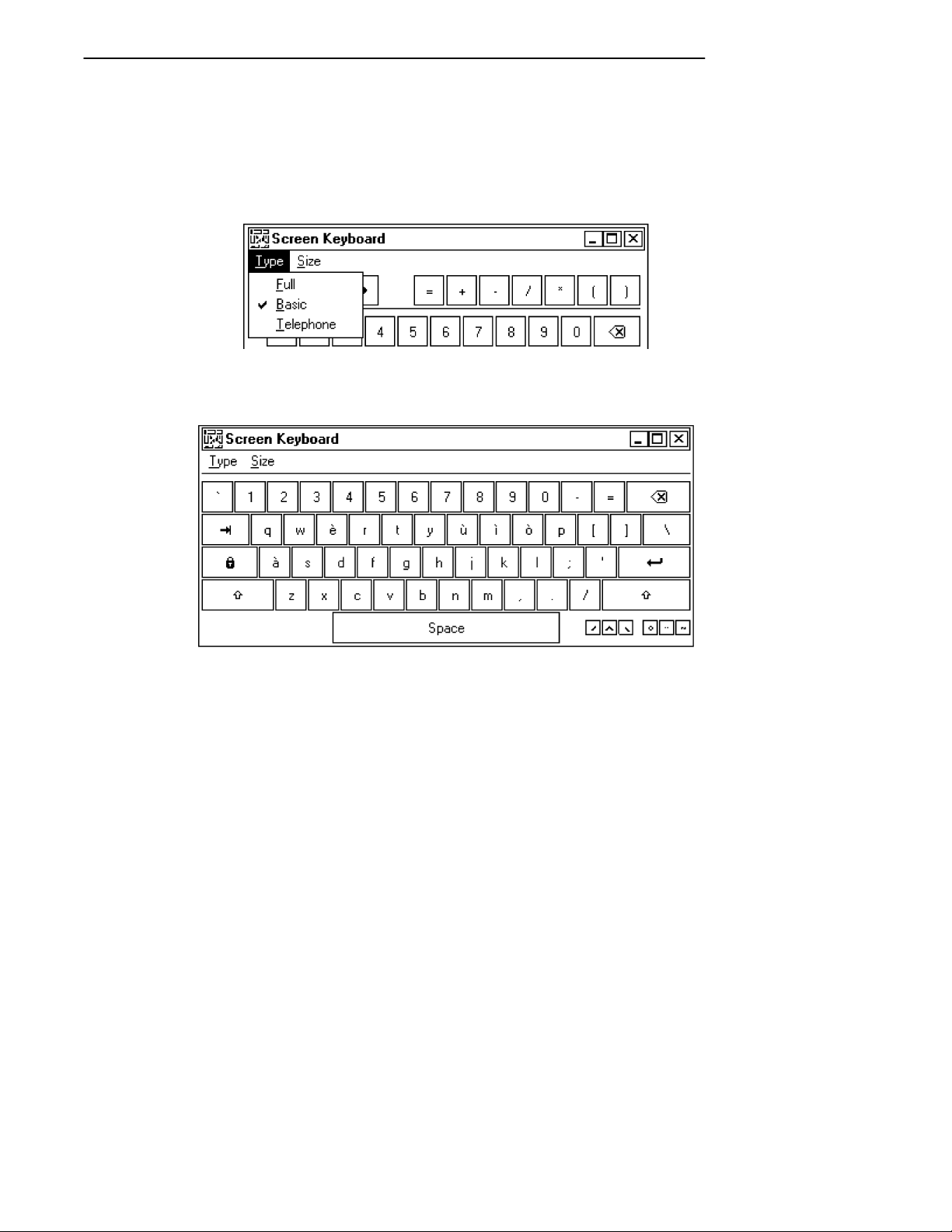
You can alter the type or size of this keyboard. Pictured
above is the basic keyboard of normal size.
From the Screen Keyboard’s menu bar, select
Type ®® Basic to use the above keyboard:
Select Type ®® Full for a full-sized keyboard that includes
more punctuation marks and other symbols:
6620 Hand-Held Computer Technical Reference 1-15
Page 28
SECTION 1Introduction
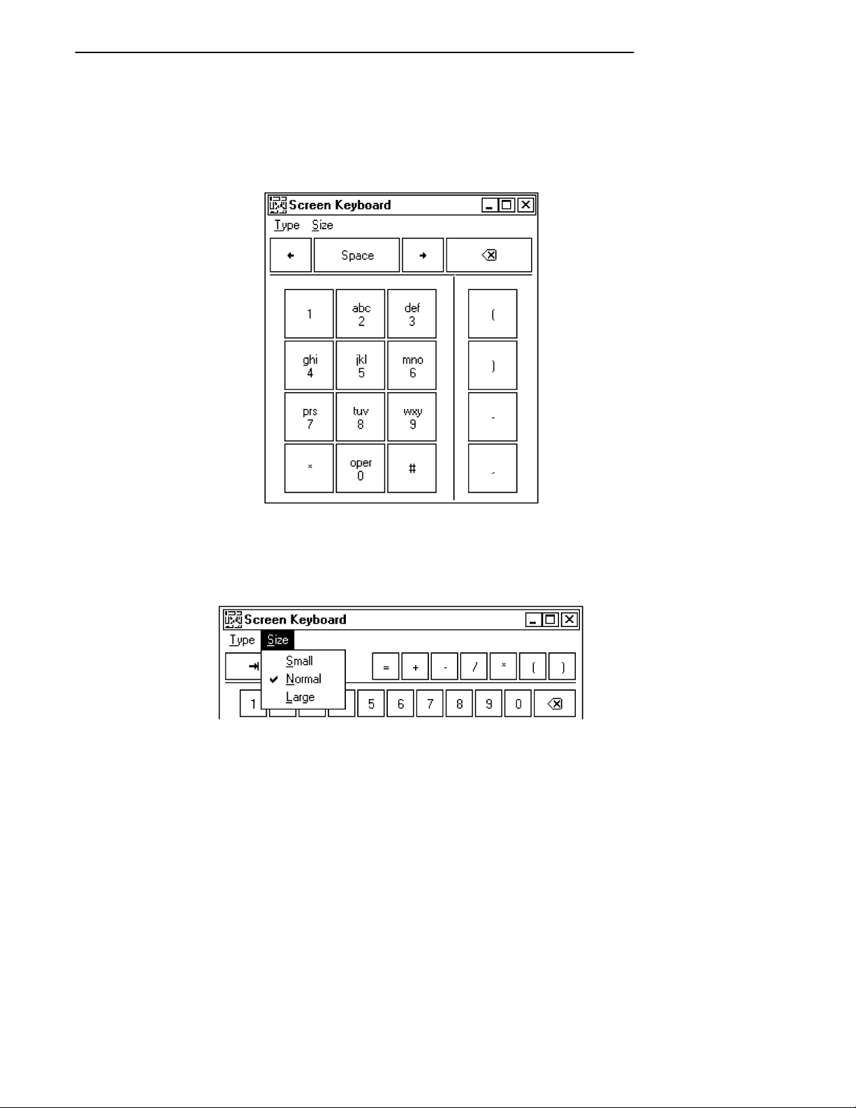
Select Type ®® Telephone for a numeric keyboard that re-
sembles that of a digital telephone, but includes the punctuation marks where necessary for proper telephone number entries:
All three keyboards pictured previously are of normal size.
You can also elect to make the keyboard large or small. Use
the Size menu on the Screen Keyboard title bar to make
the change:
1-16 6620 Hand-Held Computer Technical Reference
Page 29

SECTION 1 Introduction
Microsoft Visual Basic for Windows
Microsoft Visual Basic (VB) for Windows, is an easy-to-use
tool that lends itself to quick creation of prototype screens
for customer demonstrations and reviews. It includes
screen drawing plus an easy method for inserting code to
control the application. A few warnings, however, are in
order.
If frequently used forms are not preloaded, the screen drawing may be slow. Also, the data-aware controls are very
nice, but supporting a database with these controls consumes a lot of memory. VB can handle a large number of
databases, including dBase, Access, Paradox, and Foxpro.
It can also handle ASCII and text files.
When you encounter a Visual Basic program, you should be
aware of some common requirements.
" Files with the VBX and OCX extensions are Visual
Basic custom controls. These files support common
features (such as command buttons, list boxes, pen
edit boxes, data-aware controls, etc.) that are frequently seen in Windows applications. They are typically distributed with the application requiring them.
" Programs written in Visual Basic V4.0 can be com-
piled for 16-bit or 32-bit mode, depending on installation. Visual Basic 5.0 is 32-bit mode only.
Microsoft Visual C++ or Borland C++ for
Windows
Microsoft Visual C++ or Borland C++ for Windows are tools
for experienced C Windows programmers. The foundation
class libraries or the object windows library can be used;
just make sure to watch for space limitations because they
are statically linked. Windows programs, in general, grow
to a large size quickly and can require a lot of extra DLLs,
OCXs, or VBXs.
6620 Hand-Held Computer Technical Reference 1-17
Page 30

SECTION 1Introduction
Pen for Windows 2.0
Pen for Windows 2.0 consists of standard Windows with extra files, some changes to SYSTEM.INI, and a new file
called PENWIN.INI. Pen Extensions for Windows provides
character recognition and an easier interface for capturing
ink. A handwriting capture engine must be purchased separately, either through Norand Mobile Systems Division or
other sources.
Other Environments
Obviously, any development environment, that runs on the
aforementioned operating systems, may potentially be used
to develop software for the 6620 Computer. However, not
all of the development environments will necessarily work
as well, nor are they recommended. This is mainly, because
of storage capacity and speed limitations of the 6620 Computer.
There are other usable development environments. Here
are some guidelines that can help to determine whether a
particular environment is viable for a 6620 application.
" How much space is required?
Many environments assume the target machine is a
desktop or laptop with virtually unlimited hard drive
space. This may not be the case if the target system is
to run off an ATA card. Keep storage requirements in
mind during development. For example, Power Builder is a very popular environment for development.
However, just to get an application started, Power
Builder uses more than 3 MB of DLLs in addition to
Windows just to run the Hello World program.
" The 6620 Computer uses an AMD 5X86, 133 MHz
processor. Test the performance of your application on
a comparable computer.
1-18 6620 Hand-Held Computer Technical Reference
Page 31

SECTION 1 Introduction
Related Publications
" PEN*KEY Model 6620 User’s Guide
(P/N: 961-028-101)
" SE 1223 Scanner User’s Guide
(P/N: 961-032-042)
Customer Support
If you have any questions about application development
for the 6620 Hand-Held Computer or need additional technical support, contact Customer Support at 800-755-5505
(U.S.A. or Canada) or 425-356-1799 for personal consultation.
The fax number for Customer Support is 1-319-369-6832.
You can also use the following email address to contact Cus-
tomer Support with a problem or question:
crc@norand.com
Be sure to include your name, your company name and address, phone number and email address where you (or your
customer) can be reached, Value-Add Reseller (VAR) information if equipment was purchased through a VAR, and a
description of the problem (as specific as possible).
6620 Hand-Held Computer Technical Reference 1-19
Page 32

Bulletin Board
The Customer Support Bulletin Board (BBS), provided by
Norand Mobile Systems Division, is also a source for additional software and documentation:
" Phone number: 319-369-3515 (14.4 Kbps modem)
319-369-3516 (28.8 Kbps modem)
" Protocol: Full duplex, ANSI or ANSI-BBS; 300 to
28,800 bps; v.32bis; 8 bits, no parity, 1 stop bit. For
high-speed modems, disable XON/XOFF and enable
RTS/CTS.
If signing on for the first time, type “new” and follow the
instructions. The BBS takes you through a new user signup procedure.
"
NOTE: The Customer Support BBS File Libraries, including Hot Tips and
Product Awareness Bulletins, are available on the Internet to authorized BBS users. Contact Customer Support for a current URL address.
SECTION 1Introduction
Intermec Web Site
Use the following URL to access the Intermec Technologies
Corporation Web Site on the Internet:
http://www.intermec.com
A PDF online version of this manual will be available via
the following URL:
http://www.intermec.com/manuals/english
1-20 6620 Hand-Held Computer Technical Reference
Page 33

Section 2
Toolkit for the 6620 Computer
" " " " " " " " " " " " " " " " " " " " " " " " " " " "
This section deals with how software, drivers, and tools are
created, supported, and packaged for the 6620 Computer.
The file complement in the Toolkit for the 6620 Computer
differs from one release to the next. For an accurate list of
Toolkit files, refer to the RELNOTES.TXT file, included in
the Toolkit distribution package.
The Toolkit contains Windows resources for configuration,
power management, communications, and peripherals.
Toolkits are available, as follows:
Part Number (PN) Description
215-907-001 6620 Windows Toolkit, with manual*
215-903-001 6620 Windows Toolkit, without manual
230-055-001 6620 Windows Toolkit CD (media)**
* The “manual” refers to the 6620 Hand-Held Computer Techni-
cal Reference P/N: 977-054-007
** The manual is provided on the CD in PDF format. There is
no hardcopy manual in this kit.
The files and documentation in the Toolkit are available to
purchasers of the 6620 Computer, who holds a Windows 95
license through Intermec Technologies Corporation.
The 6620 Computer, as shipped from the factory, has preloaded the boot media with Windows 95. In the case of a
6620 Hand-Held Computer Technical Reference 2-1
Page 34

hard drive system, this also includes all Windows 95 installation files typically shipped on a Windows 95 CD. In the
case of 40 or 85 MB ATA flash drives, only a stripped down
version of Windows 95 is loaded.
The Toolkit does not include application software. Obtain
such software from Norand Mobile Systems Division, from
third-party suppliers, or design your own.
6620 Toolkit Set Up
The Toolkit contains the following drivers and utilities that
are installed on the 6620 Computer prior to shipping. Most
components are optional (and marked as such) and can be
installed via the toolkit utility found on the CD-ROM and
are part of the default hard drive load.
SECTION 2Toolkit for the 6620 Computer
" Video Drivers
The OPTI video drivers are installed to the
C:\Windows\System directory. You must ensure that
Windows is actually using these files for their current
video settings.
" Pen and Handwriting Drivers
The PEN drivers are installed in the C:\6620Utilities
directory. The “Microsoft Pen Extensions for
Windows” are also installed.
" GPS Drivers (Optional)
GPSHOOK.VXD is installed in the
C:\Windows\System directory and hooked in the
Registry.
GPSOFF.COM, GPSON.COM, and JUPITER95.EXE
(and support files) are installed into the
C:\6620Utilities\gps directory. Icons are made for
these programs. More information in Section 4.
2-2 6620 Hand-Held Computer Technical Reference
Page 35

SECTION 2 Toolkit for the 6620 Computer
" General Utilities (Optional)
The “Disk Tools,” such as CMOS.EXE, FLASH.EXE,
and PARTUTIL.EXE, are installed into the
C:\6620Utilities\disk directory and directly added to
your path.
" PCMCIA Support
NPCCARD.VXD is installed into the C:\Windows\System directory and hooked into the Registry.
" Advanced Power Management
VNPOWERD.VXD is installed into the
C:\Windows\System directory and hooked into the
Registry.
" EricssonM2100 Series WirelessPCCard(Optional)
See Section 6 for more information.
" Tethered Scanner Driver (Optional)
W95TSCAN.DRV (NORAND Tethered Scanner Driver) files are installed into the C:\Windows\System
directory.
" MS Windows 95 Infrared Support 2.0 (Optional)
The “MS Windows 95 Infrared Support 2.0” setup files
are currently installed into the
C:\6620Utilities\MSIr20 directory. You will be
prompted to start the “Microsoft IR Hardware
Wizard.” You can elect to start the Microsoft setup to
install IR support, and can uninstall the setup files
when they are done. Information about the IR support
is found in Section 7.
" TDK 2814C Modem Support (Optional)
The TDK setup is factory-installed.
6620 Hand-Held Computer Technical Reference 2-3
Page 36

SECTION 2Toolkit for the 6620 Computer
" Dock Lock Utility (Optional)
Files are installed to the C:\Windows\System
directory. A Configure Dock Lock icon is on the
Windows desktop so that you can run SYSTRAY2.EXE
to access the “Configuration” window to configure
password protection.
" Battery Meter (Optional)
Files are installed to the C:\6620Utilities directory. A
Battery Meter icon is on the Windows desktop so you
can access the following monitor that measures the
total battery power available on the 6620 Computer.
" RAM Radio Support (Optional)
RAM.VXD is installed into the C:\Windows\System
directory and hooked into the registry. This driver requires that the PC Card support already be installed.
2-4 6620 Hand-Held Computer Technical Reference
Page 37

SECTION 2 Toolkit for the 6620 Computer
" CDPD Radio Support (Optional)
CDPD (Cellular Digital Packet Data) Radio drivers
(CDPD.VXD and NPCCARD.VXD) are installed into
the C:\Windows\System directory and assists in
power-managing the modem device.
" CDPD Radio Diskettes (Optional)
The contents of the CDPD Radio disks can be copied to
four floppy disks (clean disks as the A:\ drive is not
formatted) or to a subdirectory of your choice. These
files will install the “Sierra Wireless Expert” and
“Watcher” applications onto your 6620 Computer. See
Section 9 for more information.
" Internal Scanner Driver (Optional)
PODSCAN.DRV (internal scanner driver) files are
installed into the C:\Windows\System directory. See
page 1-7 for information about initializing the internal
scanner before use.
6620 Support Files
" 662NVPRM.EXE
Serial number, Ethernet EEPROM, nonvolatile data
programmer.
Usage:
662NVPRM (no parameters)
Comments:
User is prompted for necessary information.
" ATACOPY.EXE
ATA duplication utility.
Usage:
ATACOPY (no parameters)
Comments:
The SOURCE ATA must be booted from slot 0. The
TARGET ATA must be in slot 1.
6620 Hand-Held Computer Technical Reference 2-5
Page 38

SECTION 2Toolkit for the 6620 Computer
" CMOS.EXE
CMOS Editor, V1.01. Displays or modifies CMOS values.
Usage:
CMOS {address[=value] | address-address}
Comments:
CMOS.EXE can read the value at an address or range
of addresses. It can also write a value at a single address. The CMOS checksum is updated automatically
if any values are written.
" CRC32.EXE
File Integrity Verification Utility
Usage:
CRC32 [@][filename | pathname] [/s]
where:
" filename is the filename on which the CRC is
calculated. One or more files or directories can
be processed at one time.
" pathname is the location of the file to be pro-
cessed. Wildcard processing is not allowed (in
the pathname specified after the “@” symbol, nor
any of the pathnames within the argument file).
" /s indicates all subdirectories should be
searched for matching file names.
" @ is (optionally) included in front of the filename
to indicate it is an argument file, which contains
names of files to be checked by CRC32.EXE.
Comments:
Refer to the Toolkit RELNOTES.TXT file for the CRC
values for each module used on the 6620 Computer.
2-6 6620 Hand-Held Computer Technical Reference
Page 39

SECTION 2 Toolkit for the 6620 Computer
" EEPROG.EXE
Dock EEPROM programmer.
Usage:
EEPROG (no parameters)
Comments:
Restores the factory defaults to the dock EEPROM.
" FLASH.EXE
BIOS flash update program.
Usage:
FLASH {/w [/fFILENAME.EXT]}
" /w write to flash
" /fFILENAME.EXT File which contains the flash
BIOS. If the BIOS to flash is added to
FLASH.EXE, this parameter is unnecessary. If
there is a BIOS added to FLASH.EXE, the file
size of FLASH.EXE is greater than 300K.
" GPSOFF.COM and GPSON.COM
Control GPS power.
Usage:
GPSON, GPSOFF
Comments:
To conserve power, the GPS module has dynamic power control. This can be controlled automatically by the
GPSHOOK.VXD driver, or manually through these
two programs.
6620 Hand-Held Computer Technical Reference 2-7
Page 40

SECTION 2Toolkit for the 6620 Computer
" MKBUF.EXE
Keypad test utility.
Usage:
MKBUF (no parameters)
Comments:
The screen displays an image of the keypad layout.
Pressing a key results in highlighting that key on the
display. As the <Susp> key is not attached to the keyboard controller, it cannot be tested by this program.
The program exits when one of the following events
occur:
" The 60-second timer expires.
" The user presses each keypad key five times.
" The user presses <ESC> on the keyboard.
"
NOTE: The MKBUF.EXE program does not function under Windows 95, and
must be run from a DOS prompt.
" PARTUTIL.EXE
HDD Partition Creation utility.
Usage:
PARTUTIL /? (lists parameters)
Comments:
Used during the recovery process. It is not for use by
the end-user. See “Partition Utility” on page 3-27 for
more details.
2-8 6620 Hand-Held Computer Technical Reference
Page 41

SECTION 2 Toolkit for the 6620 Computer
" PHDISK.EXE
Phoenix Suspend-to-Disk Partition Utility.
Usage:
PHDISK
{/CREATE [size] | /REFORMAT | /DELETE | /INFO}
" /CREATE [size] Create a partition on the disk
starting from the end of the disk. If size parameter is omitted, PHDISK creates a partition with a
size based on the currently available memory.
" /REFORMAT Reformat an existing partition.
" /DELETE Delete an existing partition.
" /INFO Display information on the partition.
Comments:
Used during the recovery process. It is not for use by
the end-user.
" READIMG.EXE and WRITEIMG.EXE
Disk volume imaging tools.
Usage:
READIMG drive filename.ext
WRITEIMG filename.ext drive
" drive Drive to read or write
" filename.ext Name of image file
" SWAPMON.EXE
Monitors usage inside the Windows 95 swap file to optimize swap file usage on minimum card loads.
Usage:
SWAPMON
" WIPECMOS.COM
CMOS maintenance utility.
Usage:
WIPECMOS (no parameters)
Comments:
This program clears the CMOS and erases the CMOS
backup stored in the FLASH parameter storage area.
6620 Hand-Held Computer Technical Reference 2-9
Page 42

Installing Toolkit Components
The 6620 Toolkit is on the CD-ROM. You can elect to do a
full or partial load from the CD-ROM via the “Wize Installation Wizard” application. Do the following to load the 6620
Toolkit onto your 6620 Computer:
1. Double-click the My Computer icon to access the
source directory.
2. Double-click the source directory, such as the C: drive.
3. Double-click the Drvsetup folder.
4. Double-click the Drvsetup icon (shown left) to access
the “6620 ToolKit Installation” window.
SECTION 2Toolkit for the 6620 Computer
2-10 6620 Hand-Held Computer Technical Reference
Page 43

SECTION 2 Toolkit for the 6620 Computer
5. A warning screen appears, click the Continue button
to move to the components page.
6620 Hand-Held Computer Technical Reference 2-11
Page 44

SECTION 2Toolkit for the 6620 Computer
Loading the Components
1. Use the “Select Components” window to select which
components are to load onto your 6620 Computer, then
click the Next button to continue. See next page for
executables and pages with additional information
about these components.
2-12 6620 Hand-Held Computer Technical Reference
Page 45

SECTION 2 Toolkit for the 6620 Computer
Below is a list of executables that go with each of the
components listed in the “Select Components” window.
Brief information about these components start on the
pages given in the “On Page” column.
Table 2-1
Component Executables
Component Executable On Page
Video Drivers VIDEO.EXE 2-2
Pen and Handwriting Drivers PEN.EXE 2-2
GPS Drivers GPS.EXE 2-2
General Utilities GENUTILS.EXE 2-3
PCMCIA Support PCMCIA.EXE 2-3
Advanced Power Management APM.EXE 2-3
Ericsson M2100 Wireless PC Card ERICMWPC.EXE 2-3
Tethered Scanner Driver TSCAN.EXE 2-3
MS Windows 95 Infrared Support 2.0 MSIRDA.EXE 2-3
TDK Modem Support 281 4C 5600 TDKMSUPP.EXE 2-3
Dock Lock Utility DOCKLOCK.EXE 2-4
Battery Meter Utility
Ram Radio Support
CDPD Radio Support CDPDSUPP.EXE 2-5
CDPD Radio Diskettes CDPDDISK.EXE 2-5
Internal Scanner Driver ISCAN.EXE 2-5
BATTMTR.EXE 2-4
RAMSUPP.EXE 2-4
6620 Hand-Held Computer Technical Reference 2-13
Page 46

SECTION 2Toolkit for the 6620 Computer
2. Click the Install button in the “Ready to Install! window to begin the installations.
2-14 6620 Hand-Held Computer Technical Reference
Page 47

SECTION 2 Toolkit for the 6620 Computer
Each of the components selected from the “Select Components” screen (page 2-12) is loaded separately. Before each
component is loaded, a confirmation window appears to ensure that you do want that component installed. Below is a
sample confirmation window with the component being
loaded listed in the center:
Click the Continue Installation button to continue loading that component onto the 6620 Computer. If you decide
not to load a component, click the Abort Installation button to move to the next component or to the end of the
installation.
If you click the Continue Installation button, an “Installing” window appears with two status bars, one for the current file and one for all files related to the component being
loaded.
When the component is finished loading onto the 6620 Computer, an “Install” window appears (next page) to give you
the option to either reboot the computer to update its system or continue to load the next component or to finish the
installation.
6620 Hand-Held Computer Technical Reference 2-15
Page 48

SECTION 2Toolkit for the 6620 Computer
Click the OK to reboot the system or click the Cancel to
load the next component.
Loading Infrared Support
If you had selected the “MS Windows 95 Infrared Support
2.0” component to be loaded, an “Install Note” window appears after the confirmation window for the “Infrared Support” component:
Click the Yes button to activate the “Add Infrared Device
Wizard” but wait for the other components to load and for
the installation to finish. The rest of the infrared device
installation can be done when you return to the desktop.
Steps are detailed starting on page 2-21.
2-16 6620 Hand-Held Computer Technical Reference
Page 49

SECTION 2 Toolkit for the 6620 Computer
Loading Ram Radio Support
If you select to load the “Ram Radio Support” component,
you will be able to set up the COM port and the base address. The “Select Com Port” window appears after several
files are copied into the 6620 Computer.
Click the scroll-down button to select from COM3, COM4
(default), COM5, or COM6, to which port the Ram Radio is
to connect, then click the Continue button.
Several more files are installed before the “Select Base Address” window appears:
Click the scroll-down button to select from 3E8h, 2E8h (de-
fault), 308h, or Other, to which base address the Ram Radio
is to connect, then click the Continue button to load the
next component or to finish the installation.
6620 Hand-Held Computer Technical Reference 2-17
Page 50

SECTION 2Toolkit for the 6620 Computer
Loading CDPD Radio Support
If you select to load the “CDPD Radio Support” component,
you will be able to set up the COM port. The “Select Com
Port” window appears after several files are copied into the
6620 Computer.
Click the scroll-down button to select from COM3, COM4
(default), COM5, or COM6, to which port the CDPD Radio
is to connect, then click the Continue button to load the
next component or to finish the installation.
2-18 6620 Hand-Held Computer Technical Reference
Page 51

SECTION 2 Toolkit for the 6620 Computer
Loading CDPD Radio Diskettes
The “CDPD Radio Diskettes” component consists of installation and executable files for the CDPD radio. If you select
to load this component, you will be able to dictate to where
the CDPD files are to be copied, such as a subdirectory or to
four floppy disks. Note, no formatting is done on the
A:\drive, thus use empty disks for saving the CDPD files.
Information about installing and setting up the CDPD files
start on page 2-26.
6620 Hand-Held Computer Technical Reference 2-19
Page 52

SECTION 2Toolkit for the 6620 Computer
Finishing the Toolkit Installation
When all of the selected components have been loaded onto
the 6620 Computer, the final installation screen appears.
Click the Finish button to return to the desktop.
"
NOTE: If you do not have any additional component configuration screens
on the desktop, we recommend that you reboot the 6620 Computer
for the new components to reset the computer system. If you do
have additional component configurations (such as the MS Infrared
Support component), complete those configurations, then reboot the
6620 Computer.
2-20 6620 Hand-Held Computer Technical Reference
Page 53

SECTION 2 Toolkit for the 6620 Computer
Installing MS Infrared Support
If you had clicked the Yes button from the “Install Note”
window (page 2-16) for the MS Windows 95 Infrared Sup-
port 2.0 component, continue the infrared support installation with the following steps:
1. When you return to the desktop after clicking the Fin-
ish button on the last toolkit installation page (previous page), you will see this wizard on the desktop.
Click the Next button to continue installing the infrared support:
6620 Hand-Held Computer Technical Reference 2-21
Page 54

SECTION 2Toolkit for the 6620 Computer
2. The manufacturer and model window appears with
the default manufacturer and related model highlighted. Click the Next button to accept the highlighted items and continue.
2-22 6620 Hand-Held Computer Technical Reference
Page 55

SECTION 2 Toolkit for the 6620 Computer
3. The next window responds with acknowledging the
chosen infrared device and prompts for the port to
which the infrared device is physically connected. The
default port is highlighted, thus click the Next button
to continue.
6620 Hand-Held Computer Technical Reference 2-23
Page 56

SECTION 2Toolkit for the 6620 Computer
4. This window appears with the default simulated ports.
Click the Next button to have Windows accept the default ports given and continue. The system provides
messages as it installed the infrared device.
2-24 6620 Hand-Held Computer Technical Reference
Page 57

SECTION 2 Toolkit for the 6620 Computer
5. When done, the final installation window appears.
Click the Finish button to activate the infrared device
and return to the desktop.
6620 Hand-Held Computer Technical Reference 2-25
Page 58

Installing CDPD Radio
If you had selected the “CDPD Radio Diskettes” component
to load installation and executable files onto the 6620 Computer, you can do the following to install the “Watcher” application from Sierra Wireless, Inc.
1. If you had the CDPD files copied onto four disks, insert the first disk in the floppy drive.
2. From the Windows desktop, double-click the My Com-
puter icon and either go to the floppy drive or to the
subdirectory where you had the CDPD files copied.
3. Double-click the setup icon to install the “Watcher
Setup” application from Sierra Wireless, Inc. Click the
Next button to continue.
SECTION 2Toolkit for the 6620 Computer
2-26 6620 Hand-Held Computer Technical Reference
Page 59

SECTION 2 Toolkit for the 6620 Computer
4. The standard location to store the “Watcher” application files is a “Watchers” folder within the C:\Program
Files directory. You can change the directory path by
clicking the Browse button for a “Browse” window.
Click the Next button to accept the directory path and
continue.
6620 Hand-Held Computer Technical Reference 2-27
Page 60

SECTION 2Toolkit for the 6620 Computer
5. Use this page to customize the folder name that will
contain the “Watcher” application program icons. You
can change the folder name via the Program Fold-
er(s) field. Click the Next button to accept the folder
name and continue.
2-28 6620 Hand-Held Computer Technical Reference
Page 61

SECTION 2 Toolkit for the 6620 Computer
6. After all of the “Watcher” application files and program icons are installed, you have the option to restart the 6620 Computer to update the system properties. If you elect to restart the computer, select Yes,
then click the OK button to restart the computer. If
you want to restart the computer at another time, select No, then click the OK button to return to the
desktop.
6620 Hand-Held Computer Technical Reference 2-29
Page 62

SECTION 2Toolkit for the 6620 Computer
If you want shortcut icons on the Windows desktop for the
“Watcher” and “Sierra Wireless Expert” applications, do the
following:
1. Go to the Windows desktop, then right-click your
mouse button for a pop-up menu.
2. Select New Shortcut from the pop-up menu to open
the “Create Shortcut” window.
3. Enter the following path in the Command line field
for the applicable icon:
" For the “Watcher” application:
C:\Program Files\Watcher\watcher.exe
" For the “Sierra Wireless Expert” application:
C:\Program Files\Watcher\SwiExpert.exe
then click the Next button for the “Select a Title for
the Program” page.
4. Either rename the icon from the executable filename
in the Select a name for the shortcut field, or click
the Finish button to create the shortcut.
Go to Section 9 for information about the contents of the
CDPD Radio applications.
2-30 6620 Hand-Held Computer Technical Reference
Page 63

Section 3
6620 Recovery Procedures
" " " " " " " " " " " " " " " " " " " " " " " " " " " "
Successful 6620 System Recovery can be achieved by following the exact procedures described here based on the type of
recovery you are attempting. Normal “Main Data” partition
recovery and comprehensive “Complete System” recovery
are available. The components required for disk floppy and
Netcard recovery are:
" A 6620 Toolkit CD-ROM
" A 6620 Docking Station
" An industry standard PS/2-style keyboard
" Certificate of Authenticity from Microsoft for the 6620
Computer to be recovered
and these two for floppy disk recovery:
" A 6620 Parallel Floppy Drive unit, or
" Recovery disk (which can be made on any industry
Desktop PC containing a CD-ROM drive or a network
drive and a 3.5” disk drive)
or these two for Netcard recovery:
" A 40 MB or greater ATA Card
" An empty PC Card slot
Many of the procedures documented in this manual require
the use of floppy disks to properly set up a 6620 Computer
for various tasks. Newer versions of “Recovery Windows”
include this functionality on the hard drive.
6620 Hand-Held Computer Technical Reference 3-1
Page 64

This can be accessed by booting directly to the recovery
partition, and using the menu to choose to:
" Image the “Main Data Partition”
" Set up a MASTER mode system (system duplication)
" Set up a SLAVE mode system (system duplication)
Booting to the recovery partition can be done by using the
PARTUTIL.EXE executable with the /S parameter (see
page 3-27 for Partition Utility information).
Because of this new functionality, use of the floppy disks to
perform system imaging is interrupted by a menu during
the boot of the recovery partition. Choose option 5 (exit)
and follow the instructions for the appropriate section.
Complete System Recovery
The first step involves partitioning, formatting (thus erasing all data on the hard drive), imaging, and activating “Recovery Windows.” The second step, in “Recovery Windows,”
recovers the “Main Data” partition (or complete system).
SECTION 36620 Recovery Procedures
Restoring Recovery Windows
This process restores “Recovery Windows” from an image
stored on the 6620 Recovery CD-ROM.
Using Another PC
This process restores from the CD-ROM shared with another PC on the network:
On the Remote Machine
1. Insert the 6620 Toolkit CD into the drive. If the “6620
Recovery Utility” is launched, close the utility.
2. Ensure the CD-ROM drive is shared and note its
Share name.
3-2 6620 Hand-Held Computer Technical Reference
Page 65

SECTION 3 6620 Recovery Procedures
"
NOTE: To successfully share the CD-ROM drive, you must have the follow-
ing network components installed:
" Client for Microsoft Networks
" IPX/SPX compatible protocol
" File and printer sharing for Microsoft Networks
Also, the IPX Frame Type must be set to “Ethernet II”.
"
NOTE: Apply Novell patch #TID 2939192 if Client 32 Version 2.50 is
installed on your client. For information on this patch, either contact
Customer Server at 800-755-5505 (U.S.A. or Canada) or
425-356-1799 or visit the Novell web site at:
www.support.novell.com
On the 6620 Computer to be Recovered
1. Boot with the Network Emergency Recovery Floppy.
2. Select option 1 “Re-image the Recovery Partition” from
the prompt list. The partitions are formatted and files
necessary for network support are copied onto the
main partition. Eventually, you will be prompted to
disconnect the floppy drive or eject the floppy disk.
3. Either disconnect the floppy drive or eject the floppy
disk. A prompt appears to reboot the computer.
4. Press <Enter> to reboot the computer. The C:\
prompt returns with a request for your user name and
password.
5. Enter the user name and the password.
6. Press “N” to skip creating a password-list file. Multiple passwords increase the chance of unauthorized access.
Once the imaging process is finished, the system reboots
into the “Recovery Windows” window. After entering your
name (and optionally, your company name), and accepting
the license agreement, Windows prompts you for your Certificate of Authenticity from Microsoft as it starts. You need
this information to continue the recovery.
6620 Hand-Held Computer Technical Reference 3-3
Page 66

SECTION 36620 Recovery Procedures
Using a Parallel CD-ROM Drive
It is possible to use a parallel CD-ROM to restore Recovery
Windows as long as you have real mode (DOS) support drivers as well as 32-bit (Windows) drivers that support long
filenames.
Create a CD-ROM Emergency Recovery Floppy using the
procedure described on page 3-11. Modify the
CDSUPP.BAT and CDCONF.SYS files on the floppy; these
become AUTOEXEC.BAT and CONFIG.SYS respectively
during the recovery process to support your specific CDROM drive. You also must modify CDSUPP.BAT to copy
your own driver files to the hard disk.
Recovering “Main Data” Partition
See the following “Main Data Recovery” section for detailed
instructions on this procedure.
Main Data Recovery
These methods recover the “Main Data” partition:
" Recovering from Network Drive (if network available)
" Recovering from parallel CD-ROM
" Recovering from PC Card (if a slot is available in the
6620 to be recovered)
"
NOTE: It is possible to network two different 6620 Computers in docks with a
network hub to allow for rapid reimaging or image-to-image copying.
For more information on “Image-to-Image” copying, see page 3-20.
3-4 6620 Hand-Held Computer Technical Reference
Page 67

SECTION 3 6620 Recovery Procedures
Activating the Recovery Windows
Partition
"
NOTE: Steps 1–3 are not needed if you are in the middle of a Complete
System Recovery with “Recovery Windows” already activated.
1. Boot the 6620 Computer with the 6620 Emergency Recovery Disk. The computer should be docked with the
parallel disk drive connected. Let the “Automation
Utility” start.
2. Press “2” to activate “Recovery Windows.”
3. When prompted, eject the disk to boot to the recovery
partition. The computer boots from the hard drive.
Actual Recovery of the Main Data
Partition
Recovering from Network Drive
"
NOTE: Preparing a network share and ensuring the network transports and
drivers are installed properly on the remote system is beyond the
scope of this document.
On the Remote Machine
Insert the 6620 Toolkit CD. Ensure that the CD drive is
shared and note the Share name.
On the 6620 Computer to be Recovered
Ensure that the Ethernet card is enabled in the BIOS Setup, advanced options, integrated peripherals.
1. Restart “Recovery Windows” and log in.
2. On newer systems, double-click a “Recover” icon
(shown left) from the Windows desktop. If there is a
prompt mentioning an existing drive, press “Y” for yes,
then press [Enter].
If your system does not have this icon, find the remote
share and mount it as drive Z.
6620 Hand-Held Computer Technical Reference 3-5
Page 68

SECTION 36620 Recovery Procedures
When the network drive is mapped, the “6620 Recovery Utilities” may AutoPlay. If AutoPlay fails, do the
following to manually start the recovery procedures:
a. Use “Windows Explorer” to find the CD.
b. Double-click the RUNME.BAT file to access the
“Recovery/Re-Image Utility” window:
3. Select Image the Main Data Partition, then click
the Continue button to image the main load.
3-6 6620 Hand-Held Computer Technical Reference
Page 69

SECTION 3 6620 Recovery Procedures
"
NOTE: The following warning may appear if either the Source drive or the
Destination drive could not be located.
Click the OK button to continue to the “Image” page. If either the
Source or the Destination fields are blank or contain the “Set Me”
text, like the following sample, click the applicable Browse button to
assign the correct drive.
6620 Hand-Held Computer Technical Reference 3-7
Page 70

SECTION 36620 Recovery Procedures
4. Use the applicable Browse buttons to ensure that the
network drive for the shared device (Source volume)
is selected, and that the Destination volume is the
drive assigned to the “Main Data” partition via the
“Image the Main Load” page:
5. Click the Image Main Load button. The drive is formatted and the Full Windows 95 Load is loaded.
6. When done, select the Finish button to exit the “Recovery Utility” and exit Windows. The “Main Data”
partition restores the 6620 Computer to normal.
After entering your name (and optionally, your company
name), and accepting the license agreement, Windows
prompts you for your Certificate of Authenticity from Microsoft as it starts. This is necessary to continue the recovery.
3-8 6620 Hand-Held Computer Technical Reference
Page 71

SECTION 3 6620 Recovery Procedures
Recovering from Parallel CD-ROM
Load “Recovery Windows,” then eject and reinsert the 6620
Recovery CD-ROM. If the CD-ROM fails to AutoPlay, do
the following to manually start the recovery procedures:
a. Use “Windows Explorer” to find the CD.
b. Click the right mouse button on the CD and click
the AutoPlay button. The “Recovery/Re-Image
Utility” window appears (page 3-6).
1. Select Image the Main Data Partition, then click
the Continue button to continue.
2. Click the OK button on the “Recovery Utility” warning, if it is displayed (page 3-7), to continue. Use the
applicable Browse buttons to ensure the correct CDROM drive (Source volume) is selected, and the Des-
tination volume is the drive assigned to the “Main
Data” partition via the “Image the Main Load” page
(page 3-8).
3. Click the Image Main Load button to continue. The
drive will be formatted and loaded with a “Full Load”
of Windows 95.
4. When done, click the Finish button to exit the “Recovery Utility” window, then exit Windows. The “Main
Data” partition restores the 6620 Computer to normal.
After entering your name (and optionally, your company
name), and accepting the license agreement, Windows
prompts you for your Certificate of Authenticity from Microsoft as it starts. This is necessary to continue the recovery.
6620 Hand-Held Computer Technical Reference 3-9
Page 72

SECTION 36620 Recovery Procedures
Recovering from PC Card – Method 1
See “Preparing a 6620 Boot Card (Network Recovery)” on
page 3-18 for creating the Network Recovery PC Card.
1. Set the Boot Device of the 6620 Computer to scan
PCMCIA slots (see Section 8 for CMOS Setup).
2. Insert the Emergency Recovery PC Card into a PC
Card slot. If there are other bootable PC Cards (such
as hard drives) in the system, remove them.
3. Boot the 6620 Computer. Select option 2: “Recovery
Mode” from the two menu options.
4. Another menu appears with three options. Select option 1: “Re-image the main partition.”
5. On newer systems, double-click a “Recover” icon on
the desktop and go to step 7.
If your system does not have this icon, find the remote
share and mount it as drive Z.
6. If there is a prompt mentioning an existing drive,
press “Y” for yes, then press [Enter].. Proceed to step
4 on page 3-6 under the Actual Recovery of the Main
Data Partition section.
Once the system is finished and reboots, you can remove
the PC Card and boot off the newly imaged hard drive.
Recovering from PC Card – Method 2
To prepare this recovery PC Card, you need a working sys-
tem with CD support as well as support for PC Cards.
1. Copy the files in the 6620 Recovery CD root directory
and the “Image” and “Util” directories (and subdirectories) onto the root directory of the card. Ensure there
is approximately 200 MB on the card for these files.
"
NOTE: A “6620 Boot Card” contains just the Minimal Load of Windows 95
designed for systems without spinning media. This type of card contains no recovery utilities. It is not possible to use a “6620 Boot
Card” in place of the above step.
3-10 6620 Hand-Held Computer Technical Reference
Page 73

SECTION 3 6620 Recovery Procedures
2. Insert the card containing all the files from the CDROM into the 6620 Computer to be recovered. The
card should AutoPlay. If AutoPlay fails to run, do the
following to manually start the recovery procedures:
a. Use Windows Explorer to find the card.
b. Double-click on the RUNME.BAT file. The “Recov-
ery/Re-Image Utility” window appears (page 3-6).
3. Select Image the Main Data Partition, then click
the Continue button to image the main partition.
4. Click the OK button on the “Recovery Utility” warning, if it is displayed (page 3-7), to continue. Use the
applicable Browse buttons to ensure the correct card
with all the CD-ROM files is selected for the Source
volume, and that the Destination volume is the drive
assigned to the “Main Data” partition via the “Image
the Main Load” page (page 3-8).
5. Click the Image Main Load button to continue. The
drive will be formatted and loaded with a Full Load.
6. When done, eject the card, click the Finish button to
exit the “Recovery Utility” window and exit Windows.
After entering your name (and optionally, your company
name), and accepting the license agreement, Windows
prompts you for your Certificate of Authenticity from Microsoft as it starts. This is necessary to continue the recovery.
Preparing the Recovery Floppy Disk
To prepare the recovery floppy disk for either the network
(page 3-12) or CD-ROM (page 3-14) recovery methods, insert the 6620 Recovery CD-ROM into any desktop PC with
CD-ROM support running any version of Windows 95.
The “Recovery Utility” should AutoPlay. If not, do the
following to manually start the recovery procedures:
1. Use “Windows Explorer” to find the CD.
6620 Hand-Held Computer Technical Reference 3-11
Page 74

SECTION 36620 Recovery Procedures
2. Click the right mouse button on the CD and click the
AutoPlay button.
Network Emergency Recovery Floppy
The “Recovery/Re-Image Utility” window appears for the
network emergency recovery floppy method:
1. Select Image a Network Emergency Recovery
Floppy radio button, then click the Continue button
2. Click the OK button on the “Recovery Utility” warning, if it is displayed (page 3-7), to continue.
3-12 6620 Hand-Held Computer Technical Reference
Page 75

SECTION 3 6620 Recovery Procedures
3. Use the applicable Browse buttons to ensure that the
source volume is correct and that the destination is
the disk drive via the “Emergency Network Floppy”
window. Click the Image Network Floppy button to
continue. The disk will be formatted.
"
NOTE: The version of Windows running on the desktop PC used to prepare
the disk is unimportant as all files necessary to make a bootable system on the disk are maintained on the Recovery CD-ROM.
6620 Hand-Held Computer Technical Reference 3-13
Page 76

SECTION 36620 Recovery Procedures
CD-ROM Emergency Recovery Floppy
The “Recovery/Re-Image Utility” window appears for the
CD-ROM emergency recovery floppy method:
1. Select Image a CD-ROM Emergency Recovery
Floppy, then click the Continue button
2. Click the OK button on the “Recovery Utility” warning, if it is displayed (page 3-7), to continue.
3-14 6620 Hand-Held Computer Technical Reference
Page 77

SECTION 3 6620 Recovery Procedures
3. Use the applicable Browse buttons to ensure the
source volume is correct and the destination is the
disk drive via the “Emergency CD-ROM Floppy” window. Click the Image CD-ROM Floppy button to
continue. The disk will be formatted.
"
NOTE: The version of Windows running on the desktop PC used to prepare
the disk is unimportant as all files necessary to make a bootable system on the disk are maintained on the Recovery CD-ROM.
6620 Hand-Held Computer Technical Reference 3-15
Page 78

SECTION 36620 Recovery Procedures
Preparing the Network Recovery PC Card
To prepare the recovery PC Card for the network recovery
method, do the following:
1. Insert the 6620 Recovery CD-ROM into any desktop
PC with CD-ROM support running any version of
Windows 95. The “Recovery Utility” should AutoPlay.
If not, do the following to manually start the recovery
procedures:
a. Use Windows Explorer to find the CD.
b. Click the right mouse button on the CD and click
the AutoPlay button.
The “Recovery/Re-Image Utility” window appears for
the network recovery PC Card method:
3-16 6620 Hand-Held Computer Technical Reference
Page 79

SECTION 3 6620 Recovery Procedures
2. Select Image a Network Recovery PC Card, then
click the Continue button
3. Click the OK button on the “Recovery Utility” warning, if it is displayed (page 3-7), to continue.
4. Use the applicable Browse buttons to ensure the
source volume is correct and the destination is the PC
Card slot via the “Netcard” window. Click the Image
Network PC Card button to continue. The PC Card
will be formatted.
"
NOTE: The version of Windows running on the desktop PC used to prepare
the disk is unimportant as all files necessary to make a bootable system on the disk are maintained on the Recovery CD-ROM.
6620 Hand-Held Computer Technical Reference 3-17
Page 80

SECTION 36620 Recovery Procedures
Preparing a 6620 Boot Card
"
NOTE: This pertains to a minimum load and does not work on Windows NT.
1. Insert the 6620 Recovery CD-ROM into any desktop
PC that has CD-ROM support running any version of
Windows 95 and a PC Card Dock, such as a laptop
computer with a CD-ROM drive. The “Recovery Utility” should AutoPlay. If not, do the following to manually start the recovery procedures:
a. Use Windows Explorer to find the CD.
b. Click the right mouse button on the CD and click
the AutoPlay button.
2. Select Image a Boot Card via the “Recovery/Reimage Utility” window, then click Continue.
3-18 6620 Hand-Held Computer Technical Reference
Page 81

SECTION 3 6620 Recovery Procedures
3. Click the OK button on the “Recovery Utility” warning, if it is displayed (page 3-7), to continue.
4. Use the applicable Browse buttons to ensure the
source volume is the CD-ROM and that the destination is your card to be imaged via the “Image to Minimum Load” window. Click the Image Minimum
Load button to continue. The card will be formatted.
5. Press “Y” for “Yes” to format the PC Card and copy all
“Minimal Load” files.
Using this process, you may format any size ATA Flash
disk, with a minimum of 40 MB for storage. The drive geometry does not matter when preparing an image as long as
the card can contain the Boot Card Load.
6620 Hand-Held Computer Technical Reference 3-19
Page 82

Image-to-Image Copying
This process is for those who installed the application on a
“Master 6620” unit and wish to duplicate this master image
on one or more hand-held computers.
This process assumes that you have a 6620 Desktop Dock, a
network hub, and two network cables to network either a
desktop PC (containing a full 6620 image) or another 6620
(in another single dock) to be cloned directly. Also, either a
floppy drive or access to a free PC Card slot is required.
Restoring Operation of the Source
6620 Computer (MASTER)
1. Shut down Windows and the 6620 Computer.
2. Boot the system with the Peer Networking disk.
3. Press “3” to restore normal operation, then press [En-
ter]. Once the configuration is complete, you will be
prompted to eject the floppy disk.
4. Eject the floppy disk, then press any key to boot the
system into Windows.
If the network recovery PC card is used, shut down the system and reboot without the PC Card.
SECTION 36620 Recovery Procedures
Configuring a Source 6620
Computer (MASTER)
Do these steps on the source 6620 Computer. This computer is considered the “master”:
1. Prepare the Main Data Partition exactly as you want
it set up.
2. Boot the system with the special Peer Networking diskette or PC Card created using the Toolkit CD-ROM.
3-20 6620 Hand-Held Computer Technical Reference
Page 83

SECTION 3 6620 Recovery Procedures
3. Choose the appropriate menu item to set up the system as the master, then press [Enter]. Depending on
your current configuration, the system may reboot
once without intervention. You will be prompted for a
computer name.
4. Enter a computer name that is unique on the network,
then press [Enter]. If no entry is made within five
seconds, the default (MASTER) name is used.
"
NOTE: Remember this name for the Destination (SLAVE) computer.
5. If the floppy method is used, you will be prompted to
eject the disk. The system will boot into recovery windows in the Master mode.
6. The network window appears. Select option 2 “Peer
Imaging Master Mode”.
7. Click the OK button to activate the network.
The master system should remain in this state while you
are duplicating the “slave” systems.
Configuring the Destination 6620
Computer (SLAVE)
Do these steps on the destination 6620 Computer. This
computer is considered the “slave:”
1. Boot the system with the special Peer Networking diskette or PC Card created using the Toolkit CD-ROM.
2. Press “1” to set up the system as a slave, then press
[Enter]. Depending on your current configuration,
the system may reboot once without intervention. You
will be prompted to enter a computer name.
3. Enter a computer name that is unique on the network,
then press [Enter]. If no entry is made within five
seconds, the default “Slave” name is used.
4. If the floppy method is used, you are prompted to eject
the disk. The system boots into recovery windows in
the Slave mode. The network window may appear.
6620 Hand-Held Computer Technical Reference 3-21
Page 84

SECTION 36620 Recovery Procedures
5. If this window does appear, click the OK button to activate the network.
"
NOTE: This window may not appear on the slave system, particularly when
first set up. Either way, go on to the next step.
6. Double-click the Image icon on the Windows desktop
to start the recovery process. You are prompted to enter the name of the MASTER system.
7. Enter the name of the MASTER system, if the default
name (Master) was not used. This prompt times out
after five seconds and will default to “Master”.
The duplication process copies all the files from the
source drive to the destination drive. The progress indicator will not move or give a time-remaining estimate, as the installation engine does not know the size
of your image. This is normal.
8. When the duplication process is complete, click the
Finished button.
The partitions are restored and the system restarts.
Configuring a Source Desktop PC
(MASTER)
1. Prepare the directory tree exactly as you want it set up
on the “Main Data” Partition.
2. Set up networking on the PC. Ensure that the “File
and Print Sharing” function is enabled. See page 3-30
for instructions on how to ensure this function is enabled.
3. When the system reboots, log on to Windows or networking will not activate.
Do the following to share the (MASTER) directory, containing the complete directory tree, with the (SLAVE). This directory must be structured the same as the root of the data
partition, such as having “Windows” as an immediate subdirectory:
3-22 6620 Hand-Held Computer Technical Reference
Page 85

SECTION 3 6620 Recovery Procedures
1. From the Windows desktop, double-click the My
Computer icon for the “My Computer” window.
2. Right-click the (MASTER) directory (with the complete tree) icon for the pop-up menu:
3. Select Sharing from the pop-up menu to access the
“Properties” window for the Master directory.
6620 Hand-Held Computer Technical Reference 3-23
Page 86

SECTION 36620 Recovery Procedures
4. The “Properties” window opens with the “Sharing”
page on top. Click Shared As, then type “D” in the
Share Name field to enable directory sharing.
5. Click Full under “Access Type,” then click Apply.
6. Click the Ok button to exit the “Properties” window
and return to the Windows desktop.
Do the following to assign a name to the (SLAVE) computer:
1. From the Windows desktop, right-click the Network
Neighborhood icon, then select Properties from the
pop-up menu to access the “Network” window.
2. Click the Identification tab for that page. Enter a
unique name in the Computer name field, such as
“Destination,” then click the OK button.
3-24 6620 Hand-Held Computer Technical Reference
Page 87

SECTION 3 6620 Recovery Procedures
"
NOTE: Remember this name for the (SLAVE) computer.
3. If changes are required, a prompt window appears.
Click the Yes button to restart the system. After the
restart and logon, sharing is activated.
The master system should remain in this state while you
are duplicating the “slave” systems.
6620 Hand-Held Computer Technical Reference 3-25
Page 88

SECTION 36620 Recovery Procedures
Tips
The following tips can help you do the preceding configurations more efficiently:
" Any non-Windows files that have system attributes or
hidden attributes are not copied from the master. To
override this rule:
a. “ATTRIB” these files on the master.
b. Do the copies.
c. “ATTRIB” them back onto the master.
d. Attribute them manually on the destination com-
puter.
This does not apply to most applications.
" The progress indicator does not move or give a “time
remaining” estimate, as the installation engine does
not know the size of your image.
" The entire registry of the source computer is copied to
the destination, so all Windows settings are preserved.
" When using TCP/IP, you may wish to remove key net-
working components, such as IP address, when preparing the master computer. This prevents conflicts
with the destination computer during the initial bootup.
" When entering the name of the master system, any
spaces must be replaced with the underscore ( _ ) character.
3-26 6620 Hand-Held Computer Technical Reference
Page 89

SECTION 3 6620 Recovery Procedures
BIOS Recovery
While it is rare, it is possible for the 6620 BIOS to become
corrupted. If this occurs, a loss of power while performing a
BIOS version update is the most likely cause. The 6620
Computer implements a BIOS Boot Block which allows the
system to recover from BIOS corruption in most cases.
To recover the BIOS, insert an Emergency BIOS Recovery
Floppy (provided by Intermec Technologies Corporation),
and power on the system. If the Boot Block is not corrupted, but the rest of the BIOS is, the system sounds one
long beep and two short beeps. At this point, the system
scans the floppy drive for the recovery floppy. Once found,
the disk is read into memory. About a minute after disk access stops, the system powers down. BIOS should now be
recovered.
Partition Utility
The 6620 Partition Utility replaces FDISK, Norton Disk
Editor, and PHDISK as a complete solution to create all
partitions necessary on a 6620 Computer for normal operation. Use it with the Automate Utility during the 6620 Recovery procedures. It is an MS-DOS application and must
be run in MS-DOS mode as low-level disk changes fail when
Windows 95 is running.
Installation
From the 6620 Toolkit installation, select the checkbox for
the Disk Tools. This copies the files necessary for the operation of the Partition Utility.
6620 Hand-Held Computer Technical Reference 3-27
Page 90

Operations
These are the various program options in the
PARTUTIL.EXE file and how and why to use them. You
can view the source code by typing “partutil /?” from
the DOS prompt. The general syntax for command line parameters is partutil.exe drive /arg1 /arg2 /arg3
"
NOTE: All command processing is done from left to right.
Drive: (as seen by INT13 services) 80, 81, etc. (Defaults
to 80 or C:\ )
EXAMPLE: Partutil 81 /I D:\ = 81 thus use “81” not “D:\”
Options
/Q Silent mode (no prompts or additional text)
/X Create the main data partition
/J Delete the main data partition
SECTION 36620 Recovery Procedures
/U Create the extended partition
/O Delete the extended partition
/T [!] [sectors] Create recovery partition, optional # sectors
/Y Delete the recovery partition
/C <size> Create the suspend-to-disk partition
(size is in megabytes, see example).
EXAMPLE: Partutil /C 35 creates 35 MB suspend to disk partition.
"
NOTE: If you have a 48 MB RAM 6620 Computer, use a 52 MB partition.
The general recovery process creates a 52 MB partition.
/G Delete the suspend-to-disk partition
/Z Get INT13 drive information for specified device
/I Display partition information
/E Manually edit the partition information
/R Reboot system
3-28 6620 Hand-Held Computer Technical Reference
Page 91

SECTION 3 6620 Recovery Procedures
Advanced Options
"
NOTE: Checks are in place to alert you to ill-advised activity, such as making
the last active partition inactive, etc.
Use the following commands to create backups and later fix
critical system areas changed by this application:
/WB [A:B:R] [val]
Wipe Boot Records All (/WBA),
Extended only (/WBE), or Root only (/WBR),
optional value
/WD [val] Wipe entire disk, optional value
/PN Force Normal Mode
/PE Force Emergency Mode
/PU Make recovery partition visible
/FFilename Read a snapshot file and write to disk
(the entire boot sector)
/LFilename Read disk and write a snapshot file
(the entire boot sector)
Uninstall
Erase the PARTUTIL.EXE file from the hard drive; or, run
the uninstall for the entire disk tools set as part of the 6620
toolkit.
6620 Hand-Held Computer Technical Reference 3-29
Page 92

File and Printer Sharing
The following steps show how to check if the “File and
Printer Sharing” function is enabled:
1. From the Windows desktop, double-click the My Com-
puter icon for the “My Computer” window.
2. Double-click the Control Panel icon for the “Control
Panel” window.
3. Double-click the Network icon to access the “Network” window with the “Configuration” page:
SECTION 36620 Recovery Procedures
3-30 6620 Hand-Held Computer Technical Reference
Page 93

SECTION 3 6620 Recovery Procedures
4. Click the File and Print Sharing button to access
the “File and Print Sharing” window. Ensure that
both boxes are checked. If not, check both boxes, then
click the OK button to save and return to the “Network” window.
6620 Hand-Held Computer Technical Reference 3-31
Page 94

SECTION 36620 Recovery Procedures
3-32 6620 Hand-Held Computer Technical Reference
Page 95

Section 4
GPS Drivers
" " " " " " " " " " " " " " " " " " " " " " " " " " " "
A Global Positioning System (GPS) radio communicates
with various satellites to determine the latitude and longitude of your location.
Installing the GPS Drivers from the DRVSETUP program
will install both GPSHOOK.VXD and the GPS test program.
GPSHOOK.VXD
This driver is required to power on and off the GPS radio
automatically when the COM port assigned to the radio is
opened and closed, respectively.
GPS Test Program
This program verifies the functionality of the GPS radio.
Double-click the GPS Test Program icon on the Windows
desktop to access the application.
6620 Hand-Held Computer Technical Reference 4-1
Page 96

The “Jupiter 95” window appears:
SECTION 4GPS Drivers
" Lat (Latitude)
The global latitude position of this radio via the satellite.
" Lon (Longitude)
The global longitude position of this radio via the satellite.
" INIT
Click this button to reset the radio.
" GPS Module Info
These two boxes provide information about the satellite from which you are scanning.
" Head
Indicates the current heading (in degrees) of the user.
" Speed
Indicates the current speed (miles per hour).
4-2 6620 Hand-Held Computer Technical Reference
Page 97

SECTION 4 GPS Drivers
" UTC (Universal Coordinated Time)
Also known as Greenwich Mean Time (GMT).
" Date
Current date read from the satellites.
" Log to file
Check this box if the satellite information is to be
saved to a file.
" GPS Off
Check this box if the satellite information is to be disconnected.
" Status
This field displays status information about the satellite.
" Timer
This field measures the amount of time (in seconds)
that “Jupiter 95” is open.
" CLR
Click this button to restart the Timer.
" Nav Data
This field displays the navigational data given by the
satellite.
" Sats
Status of each of the twelve receive channels, including channel number, tracking information, satellite
number, and satellite C/N.
" PDOP, HDOP, VDOP
Dilution Of Precision metrics.
6620 Hand-Held Computer Technical Reference 4-3
Page 98

SECTION 4GPS Drivers
4-4 6620 Hand-Held Computer Technical Reference
Page 99

Section 5
Entering Text
" " " " " " " " " " " " " " " " " " " " " " " " " " " "
The 6620 Computer has two methods of entering text via
the stylus pen or your finger tip. One method is a screen
keyboard which simulates the physical keyboard; the other
method is a screen palette which permits you to hand-write
your entries on the screen.
In some applications, such as the “Infrared Monitor” (see
Section 7), fields may include a text button (shown left)
with which you can access either the screen keyboard or the
screen palette.
6620 Hand-Held Computer Technical Reference 5-1
Page 100

Using the Screen Keyboard
If your 6620 unit is configured to access the electronic keyboard, the following appears:
SECTION 5Entering Text
This keyboard is much like the physical keyboard that attaches to the computer. One unique feature on this keyboard is the ability to provide four common words that start
with a letter you select.
For example, if you select the letter “d”, four words appear
beneath the text line:
If any of the four words apply, select that word. The chosen
word appears on the text line, along with a space or continue typing.
5-2 6620 Hand-Held Computer Technical Reference
 Loading...