

Page 1

6540 Stationary Terminal
GETTING STARTED
GUIDE
♦ ♦ ♦ ♦ ♦ ♦ ♦ ♦ ♦ ♦ ♦ ♦ ♦ ♦ ♦ ♦ ♦ ♦ ♦ ♦ ♦ ♦ ♦ ♦ ♦ ♦ ♦ ♦
PN: 961–047–127
Revision B
June 1999
Page 2

NOTICE The information contained herein is proprietary and is provided solely for the purpose of allowing customers
to operate and service Intermec manufactured equipment and is not to be released, reproduced, or used for any
other purpose without written permission of Intermec.
We welcome your comments concerning this publication. Although every effort has been made to keep it free
of errors, some may occur. When reporting a specific problem, please describe it briefly and include the book
title and part number, as well as the paragraph or figure number and the page number.
Send your comments to:
Intermec Technologies Corporation
Publications Department
550 Second Street SE
Cedar Rapids, IA 52401
INTERMEC, NORAND, ANTARES, NOR*WARE, TRAKKER and PEN*KEY are registered trademarks
of Intermec Technologies Corporation.
1998 Intermec Technologies Corporation. All rights reserved.
FCC Computer Compliance
NOTICE This equipment meets Class A digital device limits per Part 15 of FCC Rules. These limits protect against
interference in a commercial area. It emits, uses, and can radiate radio frequency energy. If you do not install
and use the equipment according to its instructions, it may interfere with radio signals. Using it in a
residential area is likely to cause interference. If this occurs, you must correct the interference at your
expense.
Revision B
Contact Us
Intermec Technologies Corporation
6001 36th Avenue West
P.O. Box 4280
Everett, WA 98203-9280
U.S. service and technical support: 800-755-5505 425-356-1779
U.S. media supplies ordering information: 800-227-9947
Canadian service and technical support: 800-688-7043
Canadian media supplies ordering information: 800-268-6936
Outside U.S. and Canada: Contact your local Intermec service supplier.
To receive a copy of the standard warranty provision for this product, contact your local Intermec support
services organization. In the U.S. call 1-800-755-5505, in Canada call 1-800-688-7043. Otherwise, refer to
the Worldwide Sales & Service list that ships with this manual for the address and telephone number of your
Intermec sales organization.
ii
Page 3

Introduction
Table of Contents
Section 1
Introduction to the 6540 Terminal............................................................................................ 1-1
Section 2
Set Up..................................................................................................................................... 2-1
Unpacking ....................................................................................................................... 2-1
Powering on for the First Time......................................................................................... 2-1
Section 3
Mounting and Adjusting........................................................................................................... 3-1
Desktop Configuration without Mounting Bracket ............................................................ 3-1
Supplied Hardware .......................................................................................................... 3-6
Protective Cable Cover Assembly ..................................................................................... 3-7
Supplied Hardware............................................................................................................ 3-8
Section 4
Connecting to the Network....................................................................................................... 4-1
Wired Network Connection for the Terminal..................................................................... 4-1
ODI (Novell) Network Locate the network driver files in the following directories:........ 4-1
TCPIP Network ........................................................................................................... 4-3
Wireless Proxim Connection for the Terminal................................................................... 4-5
ODI (Novell) Network.................................................................................................. 4-5
TCPIP Network ........................................................................................................... 4-8
Network Configuration................................................................................................. 4-9
Token Ring Network Connection.....................................................................................4-11
ODI (Novell) Network.................................................................................................4-11
Configuration of the Token Card .................................................................................4-13
TCPIP Network..............................................................................................................4-14
Section 5
Storing Programs and Data...................................................................................................... 5-1
Copying Files to the Terminal........................................................................................... 5-1
BIOS Version 3.0 or Newer.......................................................................................... 5-1
BIOS Older than Version 3.0 ........................................................................................ 5-1
Disk Drives...................................................................................................................... 5-2
Solid State Disks–Models DFB and DSB...................................................................... 5-2
ROM Disk (Drive A:)................................................................................................... 5-2
Flash Disk (Drive B:)................................................................................................... 5-2
SRAM Disk–Model DSB Only (Drive C:).................................................................... 5-2
Hard Drive–Model DHB (Drive C:).............................................................................. 5-3
Virtual Disk (D:).......................................................................................................... 5-3
CONFIG and AUTOEXEC Files ..................................................................................... 5-3
CONFIG.SYS.............................................................................................................. 5-4
USERCONF.SYS........................................................................................................ 5-4
AUTOEXEC.BAT....................................................................................................... 5-4
USER.BAT.................................................................................................................. 5-4
iii
Page 4

Introduction
Mini ROM DOS.............................................................................................................. 5-4
Full ROM DOS ............................................................................................................... 5-4
Section 6
Display and Keyboard.............................................................................................................. 6-1
Principle of Operation...................................................................................................... 6-1
Configuring the Display ................................................................................................... 6-1
Writing to the Display...................................................................................................... 6-2
Simulating a Large Block Cursor ..................................................................................... 6-2
Writing Applications for the Display ................................................................................ 6-2
Keyboard......................................................................................................................... 6-5
Using an External Keyboard............................................................................................. 6-6
Special Keyboard Versions............................................................................................... 6-6
Reduced Keys .............................................................................................................. 6-6
European Layout .......................................................................................................... 6-8
Section 7
Inputs and Interfaces ................................................................................................................ 7-1
Connecting Bar Code Scanners and Magnetic Stripe Readers ............................................ 7-1
Parallel Port ..................................................................................................................... 7-2
Section 8
ROM-DOS for Models DFB and DSB..................................................................................... 8-1
Internal ROM-DOS Commands ....................................................................................... 8-1
External ROM-DOS Commands ...................................................................................... 8-4
Section 9
Configuring the Bar Code Decoder ........................................................................................... 9-1
Installing the Configuration Software on a PC .................................................................. 9-1
Creating a Configuration File........................................................................................... 9-1
Modify Parameters....................................................................................................... 9-2
Saving the File ............................................................................................................. 9-2
Quitting the Program.................................................................................................... 9-2
Loading a Configuration File into the Bar Code Decoder................................................... 9-2
Section 10
Troubleshooting......................................................................................................................10-1
Unit does not boot...........................................................................................................10-1
Do you hear tones when you boot the unit?......................................................................10-1
Do you see characters on the display? ..............................................................................10-1
Does the unit hang on a command?..................................................................................10-1
Is the following line causing the problem?....................................................................10-1
Mini-Command appears at boot.......................................................................................10-2
Cannot copy files to A or B drives...................................................................................10-2
Are you trying to copy files to the A drive?..................................................................10-2
Are you trying to copy files to the B drive? ..................................................................10-2
Scanner is not working....................................................................................................10-2
Does the scanner appear to be powered up and registering good reads? .........................10-2
I cannot get a post or preamble configured .......................................................................10-2
iv
Page 5

Introduction
I cannot get files to the 6540 Terminal.............................................................................10-2
I cannot connect to the network .......................................................................................10-3
Appendix A
Network Drivers......................................................................................................................A-1
Appendix B
Utility Disk ..............................................................................................................................B-1
Appendix C
Rear Panel Connector Pin Assignments.................................................................................... C-1
Power Supply .................................................................................................................. C-1
Laser Scanner Port...........................................................................................................C-2
Bar Code Wand Port........................................................................................................ C-2
External Keyboard Port....................................................................................................C-2
COM1 and COM2 Ports..................................................................................................C-3
LPT1 Port........................................................................................................................ C-3
10BASE-T Port............................................................................................................... C-4
10BASE2 Port................................................................................................................. C-4
Appendix D
Configuration Bar Codes..........................................................................................................D-1
Configuration Commands ........................................................................................................D-2
Family A: Audio Management and Data Transmission...................................................... D-3
Family B: Bar Code Formats ............................................................................................D-6
Family C: Code 39 Parameters.........................................................................................D-7
Family D: Interleaved 2 of 5 Parameters...........................................................................D-9
Family F: UPC/EAN Parameters....................................................................................D-11
Family G: UPC/EAN Parameters ................................................................................... D-13
Family H: Parameters for Code 128, MSI, Plessey and Code 93 .....................................D-15
Family I: Advanced Features.......................................................................................... D-17
Full ASCII Bar Code Chart (HEX 00 - 2F).................................................................D-18
Full ASCII Bar Code Chart (HEX 30-5F)...................................................................D-19
Full ASCII Bar Code Chart (HEX 60-7F)...................................................................D-20
v
Page 6

Introduction
vi
Page 7
Section 1
2
Introduction to the 6540 Terminal
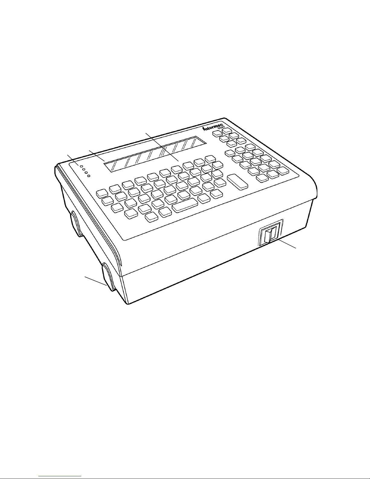
The 6540 Terminal is a rugged PC-based data collection terminal. In most respects it is like a
DOS PC. Application developers can easily write custom applications for this terminal. Its
Ethernet interface makes it easy for network administrators to manage.
3
1
4
5
1. Status indicators
2. Display
3. Keypad
4. Power switch
5. Rubber nonskid feet
Figure 1-1
Desktop Configuration
In other respects, however, it is different from a standard desktop PC. In particular, the terminal’s
display is smaller than a standard PC. You must adapt applications for the display.
In addition, the solid state disk and data storage devices of Models DFB and DSB are different
from a desktop PC that typically uses a hard drive. The DFB Model has a flash drive instead of
the standard disk drive. Flash is a different type of stable storage with faster access than a disk
drive because it has no moving parts. The DSB Model has an SRAM (Static Random Access
1-1
Page 8
Section 1 Introduction to the 6540 Terminal
Memory) drive. The SRAM drive is faster than the other models, but contents of its memory are
lost if power fails. The DHB Model has a standard disk drive.
In addition, its enclosure is specialized for the requirements of industrial environments. It is
designed for permanent mounting to a desktop or wall.
LocalName is the name of the file, including path as it will be found on the hand held computer.
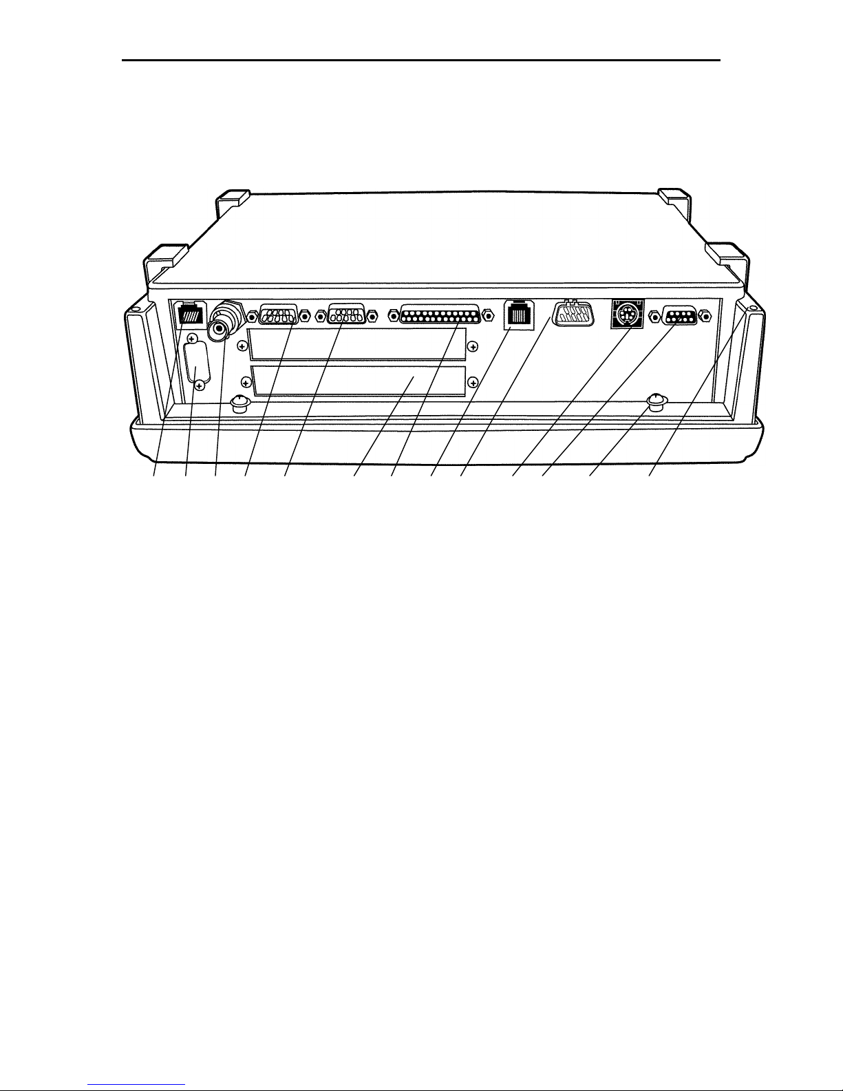
1 3 4 5 7 8 9 10 11 12 1362
1. 10BASE-T jack
2. VGA port (optional)
3. 10BASE2 connector
4. COM 2 port
5. COM 1 port
6. Wireless ethernet slot (optional)
7. LPT 1 printer port
8. CCD wand scanner or magnetic stripe reader jack
9. CCD wand or laser scanner port
10. Wedge scanner or external keyboard (P/S2 type)
11. Power supply
12. Spacer post for cable cover
13. Mounting hole for cable cover
Figure 1-2
Connector Panel
1-2
Page 9

Set Up
Unpacking
Several different models are available, and each can be ordered with a range of options and
accessories. When unpacking, check the packing list against your order, and ensure that all
of the listed options and accessories are present.
Accessories are all visible, and their presence is easy to verify. The connectors for optional
add-on cards should be visible through the rear panel. The CPU type and speed, and the
memory configuration are reported on the display when the unit goes through its self-test
upon power up.
Powering on for the First Time
All units are thoroughly tested at the factory. Nonetheless we recommend you power up
each unit upon receipt to verify that it is operating normally. Powering up the unit requires
connecting the power supply to the proper port on the unit’s rear panel and positioning the
power switch in the “on” position (marked I). The unit runs a power-up self-test that reports
the status of its main systems and terminates at a DOS prompt. Scanners connected to the
scanner ports work normally. The unit is ready to connect to an Ethernet network.
Section 2
2-1
Page 10

Section 2 Set Up
2-2
Page 11
Section 3
Mounting and Adjusting
The terminal rests on desktop or is permanently mounted to a desktop or wall using its adjustable
mounting bracket accessory. Its protective cable cover accessory attaches to the top panel of the
unit, to provide environmental protection.
Desktop Configuration without Mounting Bracket
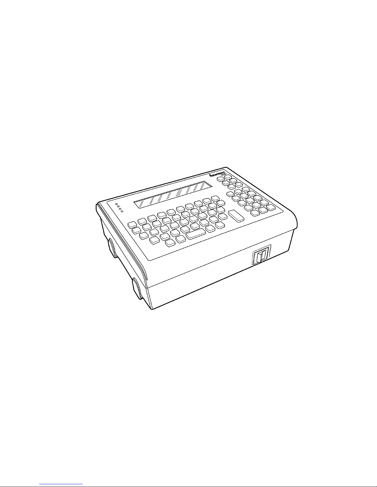
In the desktop configuration without the adjustable mounting bracket, the supplied feet should be
attached as shown in Figure 3-1. When an adjustable mounting bracket is ordered with the unit
the rubber feet are not supplied.
Desktop Configuration without Adjustable Mounting Bracket
Figure 3-1
3-1
Page 12
Section 3 Mounting and Adjusting
3-2
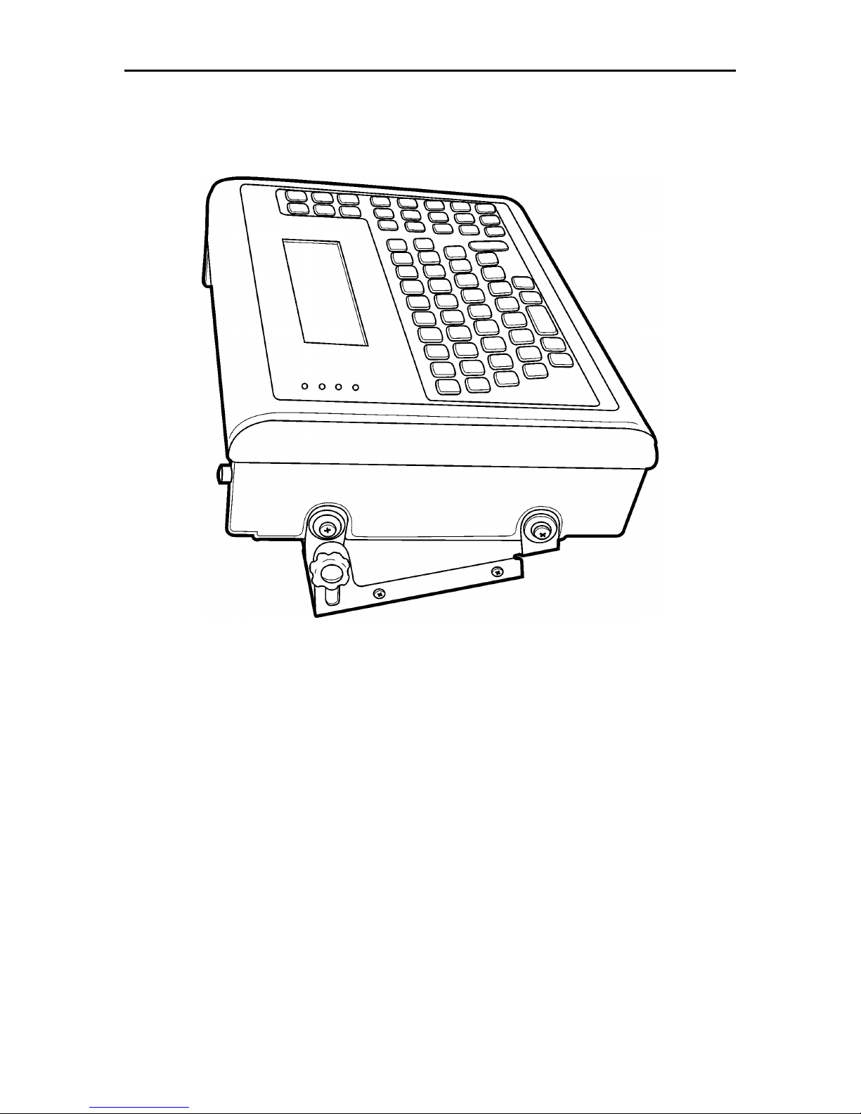
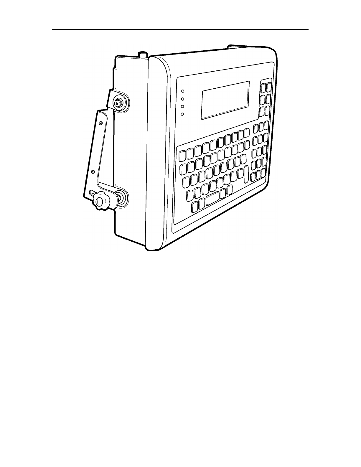
The following illustrations show how you can permanently attach the terminal to a desk or wall
with the optional mounting bracket.
Figure 3-2
Desktop Configuration with Adjustable Mounting Bracket
Use the adjustable mounting bracket (part number 2-486015-20) for either surface. Once the
bracket is installed, you can tilt the terminal from 0 to 15 degrees, by loosening the thumbscrews,
tilting the unit, then retightening the screws.
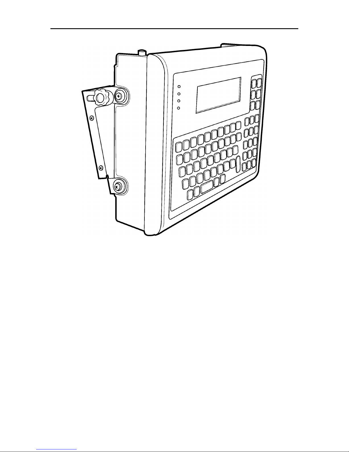
You can permanently mount the terminal to a wall using the adjustable mounting bracket. Note
that the recommended orientation of the bracket depends on the position of the unit with respect
to the operator.
Page 13
Section 3 Mounting and Adjusting
3-3
Figure 3-3
Wall Mount Orientation Below Shoulder Level
Page 14
Section 3 Mounting and Adjusting
3-4
Figure 3-4
Wall Mount Orientation Above Shoulder Level
Page 15

Section 3 Mounting and Adjusting
3-5
Drill holes where indicated using a drill size appropriate for the permanent fastener you plan to use.
Affix bracket to countertop or wall using a fastener you supply. (Do not exceed 10-32 size fastener.)
Press two of the four vibration-damping grommets into the mounting bracket and two into the J-shaped
Attach two J-shaped brackets to the terminal by inserting the pan-head screws through the flat washers and
the slots on the J-shaped brackets, then through the vibration damping grommets, then into the mating
inserts in the case. You may need to remove the nonskid feet to expose the mating inserts. If so, simply
pull off the feet to uncover the inserts.
Attach the main brackets to the terminal by inserting the pan-head screws through the flat washers and
vibration damping grommets, then into the mating inserts in the case.
Insert thumbscrews through the main bracket and screw them into the inserts on the J-shaped brackets.
Once installed, you can tilt the terminal up to 15 degrees by loosening the thumbscrews, tilting the terminal,
retightening the screws.
Template for Drilling Bracket Holes
8”
bracket.
Instructions:
1. Cut out template along the dotted line.
2. Tape template to desired location.
3.
4.
5.
6.
4”
Figure 3-5
them
7.
8.
9.
Page 16
Section 3 Mounting and Adjusting
3-6
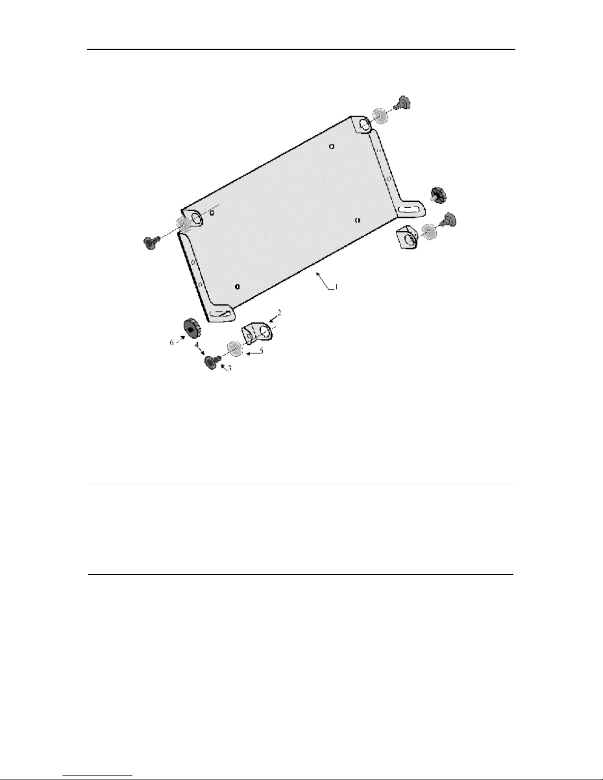
Figure 3-6
Mounting Bracket Hardware
Supplied Hardware
Item
1. Mounting Bracket 12” x 6” x 2.5” (30 x 15 x 6 cm) 1
2. J-Shaped Bracket 0.75” x 0.50” x 2.0” (2 x 1 x 5 cm) 2
3. Pan Head Screw #10 - 32 x 0.375” Phillips 4
4. Flat Washer #10 4
5. Vibration Damping Grommet 4
6. Thumb Screw #10 - 32 x .0375” 2
Quantity
Page 17
Section 3 Mounting and Adjusting
3-7
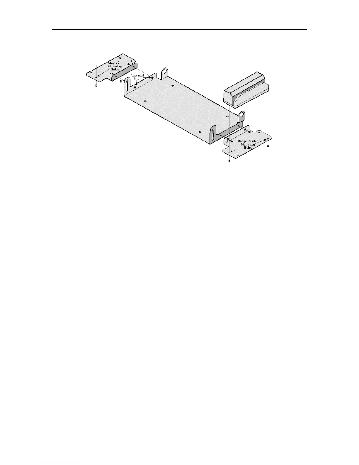
Figure 3-7
Badge Reader Attachment to Mounting Bracket
The badge reader bracket can be installed on either side of the mounting bracket as shown. The
badge reader includes two supplied screws (#4.40 x 0.250” L). Insert them as shown through the
bracket and into the threaded inserts in the adjustable mounting bracket. Attach the badge reader
to the badge reader bracket using screws supplied with that product.
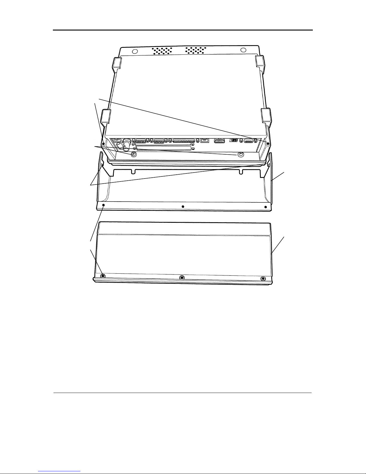
Protective Cable Cover Assembly
1. Place unit face down on its keyboard.
2. Position tabs on the protective cover into the matching holes on the case of the unit.
3. Rotate the cover so that the notches align with the spacers on the two screws in front of
the connector panel.
4. Press the cable cover into place against the screw spacers until firmly seated.
5. Attach all desired cables to appropriate ports.
6. Lay cables across the edge of the cover with the screw holes.
7. Lay platform on cable cover.
8. Turn the terminal over, so its keyboard is facing up. Secure the cover with the supplied
screws. The foam liner on the inside edge of the cover protects the cables.
Page 18
Section 3 Mounting and Adjusting
3-8
46351
2
LocalName is the name of the file, including path as it will be found on the hand held
computer.
1. Cable cover
2. Platform
3. Screw holes for securing front to back
4. Notch to put in hole on terminal
5. Mounting screws with spacers
6. Hole for cover tab
Figure 3-8
Protective Cable Cover Assembly
Supplied Hardware
Item Quantity
1. Protective Cover 1
2. Platform 1
3. #6-32 Phillips Head Screw (see Figure 3-9) 3
Page 19
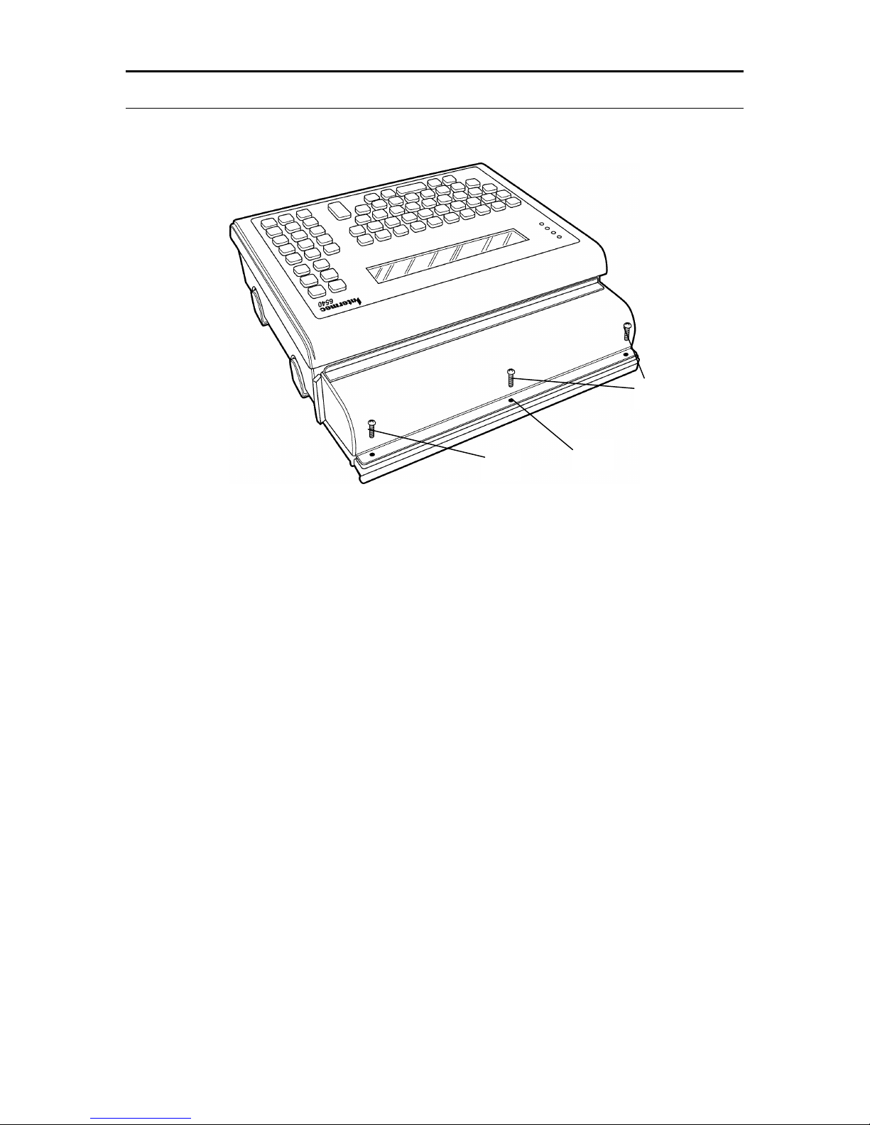
Section 3 Mounting and Adjusting
3-9
123
1. Cable exit edge
2. Screw hole for clamping screw
3. Clamping screw
Figure 3-9
Final Assembly for Protective Cable Cover
Page 20

Section 3 Mounting and Adjusting
3-10
Page 21

Section 4
Connecting to the Network
The terminal includes drivers that let you connect it to all popular networks. In Models DFB and
DSB, they are located on the FLASH (B:) drive of the terminal. In Model DHB they are located
on the hard disk drive (C:). The network drivers are loaded on the terminal based on your order.
All of the network configurations require adding, deleting, or modifying files on the B: or C: drives.
In the Model DFB and DSB, since the B: drive is a flash drive, and it is shipped in its writeprotected mode, these operations require you remove the write protection. For information on
using the flash drive, see Section 5. In the Model DHB these files are not protected, but can be by
using the standard DOS ATTRIB.EXE command.
The following sections show you what files are loaded, and what files need to be modified for your
particular configuration.
NOTE: On initial boot the unit reports errors. You must configure it for your network to remove
these errors.
Wired Network Connection for the Terminal
This section applies to the terminal with the standard onboard Crystal Ethernet connection..
Within this section are two subsections − one for ODI networks and the other for TCPIP networks.
If your terminal connects to a Novell network, follow the ODI instructions. If connecting to a
TCPIP network, follow the TCPIP instructions.
ODI (Novell) Network Locate the network driver files in the following
directories:
Model Network File Location
DFB B:\NET
DSB B:\NET
DHB C:\NET
The network files follow with a brief description of their function.
LSL.COM – Link Support Layer
EODIISA.COM – ODI Driver for terminal Onboard Crystal Ethernet chip set
IPXODI.COM – IPX driver for ODI protocol
NETX.EXE – Novell Netware communicator
STARTNET.BAT – The batch file that loads the network drivers
NET.CFG – Novell Network configuration file
4-1
Page 22

Section 4 Connecting to the Network
The terminal is configured so the following network drivers execute upon boot: USER.BAT and
STARTNET.BAT. The contents of the USER.BAT and STARTNET.BAT files follow.
USER.BAT (DFB AND DSB)
SET PATH=B:\net;%PATH%
b:
cd net
startnet.bat
USER.BAT (DHB)
SET PATH=C:\net;%path%
c:
cd net
startnet.bat
STARTNET.BAT (DSB AND DFB)
b:\net\lsl
b:\net\eodiisa
b:\net\ipxodi
b:\net\netx
set name=guest
set nwlanguage=english
STARTNET.BAT (DHB)
c:\net\lsl
c:\net\eodiisa
c:\net\ipxodi
c:\net\netx
set name=guest
set nwlanguage=English
You must modify certain files for use with your network. One is the NET.CFG file. An example
of this file follows.
4-2
Page 23

Section 4 Connecting to the Network
NET.CFG
LINK SUPPORT [Do not modify]
BUFFERS 8 1500 [Modify if needed]
MEMPOOL 4096 [Modify if needed]
MAX BOARDS 4 [Modify if needed]
MAX STACKS 4 [Modify if needed]
Link Driver EODIISA [Do not modify]
port 300 [Do not modify]
frame ethernet_II [Modify to Match your system]
frame ethernet_802.2 [Modify to Match your system]
protocol ipx e0 ethernet_802.2 [Modify to Match your system]
USERCONF.SYS (DSB)
SHELL=b:\COMMAND.COM /P
USERCONF.SYS (DFB AND DHB)
(Not Required)
TCPIP Network
Locate the network drivers in the following directories:
Model Network File Location
DFB Not Applicable
DSB B:\PCTCP and C:\ for the rloginvt.exe file
DHB C:\PCTCP
The network files are shown along with a brief description of their function.
EPKTISA.COM – Onboard Crystal Ethernet packet driver
ETHDRV.EXE – PCTCP’s TCPIP kernel
PCTCP.INI – Network configuration file for kernel
PING.EXE – Signals specific devices to confirm their connection
RLOGINVT.EXE – Remote login capabilities
TN.EXE – Telnet terminal emulation
TFTP.EXE – Telnet file transfers between different computers on the network
4-3
Page 24

Section 4 Connecting to the Network
The terminal is configured so that the following network drivers execute upon boot: USER.BAT
and STARTNET.BAT. The contents of the USER.BAT and STARTNET.BAT are shown.
USER.BAT (DFB AND DSB)
SET PATH=B:\PCTCP;%PATH%
b:\pctcp\epktisa.com 0x60 0x300
SET PCTCP=b:\pctcp\pctcp.ini
b:\pctcp\ethdrv
USER.BAT (DHB)
SET PATH=C:\pctcp;%PATH%
c:\pctcp\epktisa.com 0x60 0x300
SET PCTCP=c:\pctcp\pctcp.ini
C:\pctcp\ethdrv
USERCONF.SYS (DSB)
shell=b:\command.com /p
USERCONF.SYS (DFB AND DHB)
(Not required)
You must modify certain files to configure them for use with your network. One is PCTCP.INI
file. An example of this file follows.
PCTCP.INI
[pctcp ifcust 0]
ip-address = [Place Units IP address here]
subnet-mask = [Place Units Subnet Mask here]
router = [Place router's IP address here or remove line]
router = [Place router's IP address here or remove line]
router = [Place router's IP address here or remove line]
interface-type = PKTDRV [Do not change]
frame-type = Token-Ring [Change if you are on a different frame-type]
[pctcp addresses]
domain-name-server = [Place DNS IP Address here, else remove entire section]
4-4
Page 25

Section 4 Connecting to the Network
[pctcp general]
user = [Place user name of person using this unit, else remove line]
host-name = [Place name of machine on this line]
domain = [List the name of the domain the unit is in, else remove the line]
name-resolution = nis
[pctcp kernel]
interface = ifcust 0 [Do not change]
kernel-does-dns = yes
mtu-discovery = yes
multicast = no
pktdrv-loopback = yes
router-discovery = no
large-packets = 5
small-packets = 5
Wireless Proxim Connection for the Terminal
This section applies to the terminal with the wireless 2.4 GHz Ethernet connection. Within this
section are two subsections − one for ODI networks and the other for TCPIP networks. If your
terminal connects to a Novell network, follow the ODI subsection. If connecting to a TCPIP
network, follow the TCPIP subsection.
ODI (Novell) Network
The network driver files that have been installed on the terminal can be found at the following
directories:
Model Network File Location
DFB B:\NET
DSB B:\NET
DHB C:\NET
The network files are shown below along with a brief description of their function.
LSL.COM – Link Support Layer
RL2ISA.COM – ODI Driver for wireless 2.4GHz Proxim Ethernet card
IPXODI.COM – IPX driver for ODI protocol
4-5
Page 26

Section 4 Connecting to the Network
NETX.EXE – Novell Netware communicator
STARTNET.BAT – The batch file that loads the network drivers
NET.CFG – Novell Network configuration file
The terminal loads and executes the following network driver files upon boot up: USER.BAT and
STARTNET.BAT. The contents of the USER.BAT and STARTNET.BAT follow.
USER.BAT (DFB AND DSB)
SET PATH=B:\net;%PATH%
b:
cd net
startnet.bat
USER.BAT (DHB)
SET PATH=C:\net;%path%
c:
cd net
startnet.bat
STARTNET.BAT (DSB AND DFB)
b:\net\lsl
b:\net\rl2isa
b:\net\ipxodi
b:\net\netx
set name=guest
set nwlanguage=english
STARTNET.BAT (DHB)
c:\net\lsl
c:\net\rl2isa
c:\net\ipxodi
c:\net\netx
set name=guest
set nwlanguage=English
4-6
Page 27

Section 4 Connecting to the Network
USERCONF.SYS (DSB)
shell=b:\command.com /p
USERCONF.SYS (DHB AND DFB)
(not required)
You must modify certain files to configure them for use with your network. To do this, edit the
NET.CFG file. An example of this file follows.
NET.CFG
LINK SUPPORT [Do not modify]
BUFFERS 8 1500 [Modify if needed]
MEMPOOL 4096 [Modify if needed]
MAX BOARDS 4 [Modify if needed]
MAX STACKS 4 [Modify if needed]
LINK DRIVER RL2ISA [Do not modify]
INT 15 [Do not modify]
PORT 270 [Do not modify]
DOMAIN 0 [Modify for domain currently being used]
STATION_TYPE 0 [Modify for your network]
FRAME ethernet_802.2 [Modify for your network]
ROAM_CONFIG 1 [Modify for your network]
MAC_OPTIMIZE 1 [Modify for your network]
PEER_TO_PEER Y [Modify for your network]
protocol ipx e0 ethernet_802.2 [Modify for your network]
The wireless 2.4GHz Proxim card requires specific jumper settings. The following shows how the
switches must be set.
Jumper Settings:
1 – closed
2 – open
3 – open
4 – open
5 – closed
6 – closed
7 – open
4-7
Page 28

Section 4 Connecting to the Network
Where open is away from the number, and closed is toward the number.
TCPIP Network
The network driver files installed on the terminal can be found at the following directories:
Model Network File Location
DFB Not Applicable
DSB B:\TCPIP and C:\ for the rloginvt.exe file
DHB C:\TCPIP
The network files follow along with a brief description of their function.
RL2ISA.DOS – Onboard Crystal Ethernet NDIS driver
ETHDRV.EXE – PCTCP’s TCPIP kernel
PCTCP.INI – Network configuration file for the kernel
PING.EXE – Signals specific devices to confirm their connection
RLOGINVT.EXE – Remote login capabilities
TN.EXE – Telnet terminal emulation
TFTP.EXE – Transfers files from different computers on the network
PROTMAN.DOS – NDIS drivers
DIS_PKT.GUP – NDIS driver to a Packet driver converter
PROTMAN.EXE – NDIS drivers to Packet driver converter
NETBIND.EXE – Binds the driver to the network
PROTOCOL.INI – Configuration file to get information about the network card.
The terminal is configured so the following network driver files load and execute upon boot:
USER.BAT and USERCONF.SYS. The contents of the USER.BAT and USERCONF.SYS
follow.
USERCONF.SYS (DSB)
shell=b:\command.com /p
device=b:\pctcp\protman.dos /I:b:\pctcp
device=b:\pctcp\RL2ISA.dos
device=b:\pctcp\dis_pkt.gup
USERCONF.SYS (DHB)
device=c:\pctcp\protman.dos /I:c:\pctcp
device=c:\pctcp\RL2ISA.dos
4-8
Page 29

device=c:\pctcp\dis_pkt.gup
USER.BAT (DSB)
set path=b:\pctcp;c:\;b:\;a:\
b:\pctcp\protman.exe
b:\pctcp\netbind.com
SET PCTCP=b:\pctcp\pctcp.ini
b:\pctcp\ethdrv
USER.BAT (DHB)
set path=c:\pctcp;c:\;b:\;a:\
c:\pctcp\protman.exe
c:\pctcp\netbind.com
SET PCTCP=c:\pctcp\pctcp.ini
c:\pctcp\ethdrv
Section 4 Connecting to the Network
Network Configuration
You must modify certain files to configure them for use with your network. You must edit the
PROTOCOL.INI and PCTCP.INI files. An example of these files follows.
PROTOCOL.INI
[protman]
DriverName=PROTMAN$ [Do not modify]
[RL2ISA]
DriverName=RL2ISA$ [Do not modify]
PORT=0x270 [Do not modify]
INT=15 [Do not modify]
CHANNEL=1 [Modify for your network]
SUBCHANNEL=1 [Modify for your network]
DOMAIN=0 [Modify for your network]
STATION_TYPE=0 [Modify for your network]
MASTER_NAME=MASTER [Modify for your network]
ROAM_CONFIG=1 [Modify for your network]
MAC_OPTIMIZE=1 [Modify for your network]
4-9
Page 30

Section 4 Connecting to the Network
PEER_TO_PEER=Y [Modify for your network]
[PKTDRV]
DriverName=PKTDRV$ [Do not modify]
intvec=0x60 [Do not modify]
chainvec=0x62 [Do not modify]
BINDINGS=RL2ISA [Do not modify]
senddelay=0 [Modify if needed]
PCTCP.INI
[pctcp ifcust 0]
ip-address = [Place unit’s IP address here]
subnet-mask = [Place unit’s subnet mask here]
router = [Place router's IP address here or remove line]
router = [Place router's IP address here or remove line]
router = [Place router's IP address here or remove line]
interface-type = PKTDRV [Do not change]
frame-type = DIX-Ethernet
[pctcp addresses]
domain-name-server = [Place DNS IP address here, else remove entire section]
[pctcp general]
etc-dir = c:\pctcp\etc [Place path to “etc” directory. Stores routing port information and other
specifics]
user = [Place user name, else remove line]
host-name = [Place name of machine on this line]
domain = [List the name of the unit’s domain, else remove the line]
name-resolution = dns
[pctcp kernel]
interface = ifcust 0 [Do not modify]
You must set some jumpers for the wireless 2.4GHz Proxim card. The following shows settings.
4-10
Page 31

Section 4 Connecting to the Network
Jumper Settings:
1 – closed
2 – open
3 – open
4 – open
5 – closed
6 – closed
7 – open
Where open is away from the number, and closed is toward the number.
Token Ring Network Connection
This section applies to the terminal with the Token Ring network connection. Within this section
are two subsections − one for ODI networks and the other for TCPIP networks. If connecting to a
Novell network, follow the ODI subsection. If connecting to a TCPIP network, follow the TCPIP
subsection.
ODI (Novell) Network
The network driver files that have been installed on the terminal can be found at the following
directories:
Model Network File Location
DFB B:\NET
DSB B:\NET
DHB C:\NET
The network files follow along with a brief description of their function.
LSL.COM – Link Support Layer
TOKEN.COM – ODI Driver for the TOKEN RING Network Card
IPXODI.COM – IPX driver for ODI protocol
NETX.EXE – Novell Netware communicator
STARTNET.BAT – Batch file that loads the network drivers
NET.CFG – Novell Network configuration file
LANAIDC.EXE – Configures Token Ring Card
LANAIDC.MSG – File used by the LANAIDC.EXE file
The terminal has been configured so the following network drivers load and execute upon boot.
USER.BAT and STARTNET.BAT do this. The contents of the USER.BAT and
STARTNET.BAT follow.
4-11
Page 32

Section 4 Connecting to the Network
USER.BAT (DFB AND DSB)
SET PATH=B:\net;%PATH%
b:
cd net
startnet.bat
USER.BAT (DHB)
SET PATH=C:\net;%path%
c:
cd net
startnet.bat
STARTNET.BAT (DSB AND DFB)
b:\net\lsl
b:\net\token
b:\net\ipxodi
b:\net\netx
f:
login
STARTNET.BAT (DHB)
c:\net\lsl
c:\net\token
c:\net\ipxodi
c:\net\netx
f:
login.
You must modify certain files to configure them for use with your network. For this configuration
of the terminal, you must edit the net.cfg file. An example of this file follows.
NET.CFG
LINK SUPPORT [Do not modify]
BUFFERS 8 1500 [Do not modify]
MEMPOOL 4096 [Do not modify]
MAX BOARDS 4 [Do not modify]
MAX STACKS 4 [Do not modify]
4-12
Page 33

Section 4 Connecting to the Network
LINK DRIVER TOKEN [Do not modify]
Frame Token-Ring [Do not modify]
MAX FRAME SIZE 4296 [Modify if needed]
The wireless 900MHz Aeronet card requires some jumper settings and file manipulation. The
following shows what the switches must be set at and what files need to be created
Configuration of the Token Card
You must modify the Token card. Use these files LANAIDC.EXE and LANAIDC.MSG.
Plug the card into a PC and type the following:
lanaidc /view
This gives you a listing of the important information about the card. You must modify it so it
looks like the following:
IBM Turbo 16/4 Token-Ring ISA Adapter
PnP Support: None Detected
Adapter number: 1
Adapter MAC Address: 00 06 29 10 0C BD
MicroCode Level: 000400 P3F3A4
Serial Number: IBM1080-00C40000
Adapter Mode: ISA16
Configuration: LEGACY
Adapter State: Active
I/O Address: A20-A23
Interrupt: 9
RAM Address: D0000-D3FFF
ROM Address: D4000-D5FFF
Remote IPL: Enabled
Token-Ring data rate: 16
Auto Sense data rate: Enabled
Adapter bus width: 16
Use the following command lines to make the modifications:
4-13
Page 34

Section 4 Connecting to the Network
lanaidc /fast=isa16
lanaidc /io=a20 /config=legacy /int=9 /rom=d4000 /ram=d0000
TCPIP Network
The network driver files that have been installed on the terminal can be found at the following
directories:
Model Network File Location
DFB Not Applicable
DSB B:\TCPIP and C:\ for the rloginvt.exe file
DHB C:\TCPIP
The network files are shown below along with a brief description of their function.
IBMTOK.DOS – Token Ring NDIS driver
TOKDRV.EXE – PCTCP’s TCPIP kernel for Token Rings
PCTCP.INI – The network configuration file for the kernel
PING.EXE – Signals specific devices to confirm their connection
RLOGINVT.EXE – Remote login
TELNET.EXE – Terminal emulation
TFTP.EXE – Transfer files from different computers on the network
LANAIDC.EXE – Configures Token Ring card
LANAIDC.MSG – Used by LANAIDC.EXE
PROTMAN.DOS – Internal file
DIS_PKT.GUP – Converts NDIS driver to a packet driver
PROTMAN.EXE – Internal file
NETBIND.EXE – Binds the driver to the network
PROTOCOL.INI – Configures the Network.
The terminal has been configured so that the following network drivers load and execute upon
boot. These files are USER.BAT and STARTNET.BAT. The contents of the USER.BAT and
STARTNET.BAT follow.
USERCONF.SYS (DSB)
SHELL=B:\COMMAND.COM /P
dos=high,umb
DEVICE=b:\PCTCP\PROTMAN.DOS /I:b:\PCTCP
DEVICE=b:\PCTCP\IBMTOK.DOS
4-14
Page 35

DEVICE=b:\PCTCP\DIS_PKT.GUP
USER.BAT (DSB)
SET PATH=b:\PCTCP;%PATH%
SET PCTCP=b:\PCTCP\PCTCP.INI
b:\pctcp\protman.exe
b:\PCTCP\NETBIND.COM
b:\PCTCP\TOKDRV.EXE -p 3
CONFIG.SYS (DHB)
SHELL=c:\COMMAND.COM /P
DEVICE=c:\PCTCP\PROTMAN.DOS /I:c:\PCTCP
DEVICE=c:\PCTCP\IBMTOK.DOS
DEVICE=c:\PCTCP\DIS_PKT.GUP
Section 4 Connecting to the Network
AUTOEXEC.BAT (DHB)
SET PATH=c:\;c:\PCTCP;c:\DOS;c:\config;
SET PCTCP=c:\PCTCP\PCTCP.INI
c:\pctcp\protman.exe
c:\PCTCP\NETBIND.COM
c:\PCTCP\TOKDRV.EXE -p 2
You must modify certain files to configure them for use with your network. For this configuration
of the terminal, you must edit the PROTOCOL.INI and PCTCP.INI files. An example of these
follows.
PROTOCOL.INI
[protman]
DriverName=PROTMAN$
[TurboISA]
DriverName=IBMTOK$
RelativeUAA=1
[PKTDRV]
DriverName=PKTDRV$
intvec=0x60
4-15
Page 36

Section 4 Connecting to the Network
chainvec=0x62
BINDINGS=TurboISA
class=17
PCTCP.INI
[pctcp ifcust 0] [Do not modify]
ip-address = [Enter the IP address of the unit]
subnet-mask = [Enter the subnet mask of the unit]
router = interface-type = PKTDRV [Do not modify]
frame-type = Token-Ring [Do not modify]
[pctcp general]
host-name = [Enter a host name or remove]
domain = [Enter a domain or remove]
name-resolution = nis [Change if necessary for your network]
[pctcp kernel] [Do not modify]
interface = ifcust 0 [Do not modify]
kernel-does-dns = yes [Modify as necessary]
mtu-discovery = yes [Modify as necessary]
multicast = no [Modify as necessary]
pktdrv-loopback = yes [Modify as necessary]
router-discovery = no [Modify as necessary]
large-packets = 5 [Modify as necessary]
small-packets = 5 [Modify as necessary]
4-16
Page 37

Section 5
Storing Programs and Data
Copying Files to the Terminal
Your method for copying files to the terminal depends on its BIOS revision level. BIOS older than
revision 3.0 requires one method. Newer BIOS requires another. Reboot the terminal to find its
BIOS version. Watch the upper left corner of the display to see the revision number during the
reboot. Follow the procedure for your version of BIOS.
BIOS Version 3.0 or Newer
These instructions also work when connected to a PC that is not a network terminal.
1. Use a “null modem” cable to connect the COM1 serial port on the terminal to the COM1
port on the PC with the files to be transferred. Intermec supplies a “null modem” cable,
part number
2-653860-00.
2. On the PC type:
REMDISK
REMDISK reports to which PC drive COM1 has been mapped.
3. On the 6540 Terminal type:
REMSERV <drive letter>:
Supply the drive letter where you want to add or modify files on the 6540 Terminal.
4. On the PC you should see the drive of the 6540 Terminal as the drive reported by
REMDISK. You can edit and copy files to this drive as you would a normal drive. For
example,
COPY C:\INTERMEC\6540\*.* D:\RAMDISK\UTILITY
Where “C” represents the PC drive and “D” represents the drive reported by REMDISK.
5. Copy the files from the PC to the 6540 Terminal using the DOS copy command and the
drive letters from the previous steps
BIOS Older than Version 3.0
Use the TRANSFER utility to transfer data through a serial port link. Follow this procedure:
1. Use a “null modem” cable to connect the COM1 serial port on the terminal to the COM1
port on the PC with the file to be transferred. Intermec supplies a “null modem” cable,
part number 999.
2. On the terminal type:
5-1
Page 38

Section 5 Storing Programs and Data
TRANSFER<space>/COM1<space>/R<space>/B19200<space>[6540 destination
drive][path]filename<enter>
Example: TRANSFER /COM1 /R /B19200 B:\FILENAME.EXT <enter>
This command starts the transfer program on the terminal allowing it to receive a file from
your PC. You can specify a different name for the file on the terminal.
Note: Compress .INI and .CFG files before transferring. Use a common file compression
and extraction program to do this.
3. On the PC, type:
TRANSFER<space>/COM1<space>/S<space>/B19200<space>[6540
destination drive][path]filename<enter>
Repeat these steps for each file to be transferred.
Disk Drives
Solid State Disks–Models DFB and DSB
Models DFB and DSB use solid state devices to fill the role of conventional hard drives. They are
highly reliable and extremely fast, making them well suited for typical data collection applications.
For storage of large programs or files, or for use of conventional operating systems, including
DOS, Model DHB is available with a standard hard drive.
ROM Disk (Drive A:)
Models DFB and DSB come with a ROM disk (A: drive). It contains the core operating system
commands, the AUTOEXEC.BAT and CONFIG.SYS files, and certain drivers. Programs can be
executed normally from the A drive, but files on the drive cannot be modified or erased, and new
programs cannot be added.
Flash Disk (Drive B:)
Models DFB and DSB come with a 512K FLASH disk (B: drive), which has the advantage of
providing permanent nonvolatile storage (without requiring the use of a backup battery). Programs
contained in the flash disk execute normally. The disk can also be write protected, and the terminal
defaults to the write-protected condition on power-up. Once the write protection is removed, files
can be copied to the FLASH drive using the standard DOS COPY commands, and files can be
deleted using the standard DOS DELETE command.
Following are the applicable commands:
SSDRIVE <space> B: <space> -URemove write protection.
SSDRIVE <space> B: <space> -W Add write protection.
SSDRIVE <space> B: <space> -F Format the drive.
5-2
Page 39

Section 5 Storing Programs and Data
SRAM Disk–Model DSB Only (Drive C:)
The Model DSB can be configured with a 512KB or 1.5 MB SRAM disk (the C: drive, if present).
It operates exactly as a conventional hard disk, with the exception that permanent data storage
requires a battery backup.
Following are the applicable commands:
SSDRIVE <space> C: <space> -U Remove write protection
SSDRIVE <space> C: <space> -W Add write protection.
SSDRIVE <space> C: <space> -F Format the drive
Hard Drive–Model DHB (Drive C:)
The Model DHB can be equipped with a 1 GB+ hard drive, configured as the C: drive, which
functions exactly as a hard drive in a standard PC. A hard drive is mutually exclusive with a
SRAM drive, as described above. When a terminal is equipped with a hard drive, the SRAM and
flash are not included, however the hard drive includes a standard operating system, MS-DOS
version 6.22. The AUTOEXEC.BAT and CONFIG.SYS files are on the hard drive’s root directory.
Virtual Disk (D:)
You may create a virtual disk on any model. A virtual disk is a drive that uses standard memory
for data storage. It is volatile. If the unit loses power, you lose all data on this drive. The file
VDISK.SYS creates a virtual drive. Declare a virtual drive to be the D drive.
To create a virtual drive, add the following line to your USERCONF.SYS.
device=b:\vdisk.sys /E 3072
Then copy the VDISK.SYS file from the utilities disk to the root directory of the B drive on the
terminal.
CONFIG and AUTOEXEC Files
The Model DHB has standard AUTOEXEC.BAT and CONFIG.SYS files as with a standard PC.
The Models DFB and DSB have the same files, but they are “read-only."
In most desktop PC's the CONFIG.SYS and AUTOEXEC.BAT files are preinstalled (or installed as
part of the process of loading DOS). They may be accessed and modified by you. In the Models
DFB and DSB these files are preinstalled on the A drive. They may not be modified by you;
however each calls a file on the B drive that functions as a continuation of the CONFIG.SYS and
AUTOEXEC.BAT files, and can be modified.
The terminal boots as follows:
File Drive Access
1. CONFIG.SYS A: Cannot be modified
2. USERCONF.SYS B: Called by CONFIG.SYS, you can modify
3. AUTOEXEC.BAT A: Cannot be modified
5-3
Page 40

Section 5 Storing Programs and Data
4. USER.BAT B: Called by AUTOEXEC.BAT, you can modify
CONFIG.SYS
The CONFIG.SYS file sets the necessary hardware device drivers for the system and contains the
following statements:
DEVICE=SSDRVE.SYS /f
DEVICE=SSDRVE.SYS /s
FILES=20
BUFFERS=5
NEWFILE=B:\USERCONF.SYS
USERCONF.SYS
You may edit the USERCONF.SYS file on the B: drive, incorporating additional lines of the main
CONFIG.SYS file used to override CONFIG.SYS, e.g. Buffers = 10, can be added to override
Buffers = 5 as stated in CONFIG.SYS.
Note that when commands are added, the full path must be specified, e.g. DEVICE = B:\
PROTMAN.DOS
For Model DSB only, the USERCONF.SYS file must contain the SHELL = B:\COMMAND.COM
/P line to be able to reboot into a full ROM-DOS mode. Also, COMMAND.COM must be copied
to B drive.
AUTOEXEC.BAT
It contains the following statements:
PATH A:\;B:\;C:\;
PROMPT $P $G
USER.BAT
The commands do not display as they load.
USER.BAT
You may edit the USER.BAT file on the B: drive, incorporating additional lines of the main
AUTOEXEC.BAT file.
Mini ROM DOS
The Model DSB uses a mini ROM DOS function. This frees hexadecimal addresses C800–DFFF
for use with ISA cards. This reduced operating system makes running programs more difficult. If
you have problems running programs, follow this procedure to load the full ROM DOS.
Full ROM DOS
Reboot the terminal and press the [Caps Lock] key repeatedly. If you see the introductory screen
reboot and try again.
If you see the menu, selcct full ROM-DOS. This gives you the full operating system.
5-4
Page 41

Section 5 Storing Programs and Data
If this solved the problems, make the change permanent by inserting the following line in the
USERCONF.SYS file:
SHELL=B:\COMMAND.COM /P
While still in full ROM DOS, copy the COMMAND.COM file from A to B drive.
5-5
Page 42

Section 5 Storing Programs and Data
5-6
Page 43

Section 6
Display and Keyboard
The terminal features a 4-line by 40-character "advanced supertwist" display that provides large,
bright characters viewable from a wide angle, without requiring contrast or brightness adjustment.
We offer an optional 8-line by 40-character display.
The display can be described as a 4x40 or 8x40 window on a standard 25x80 monochrome PC
display. Programmers can use the standard, nongraphics print commands of any normal DOS
programming language to write to the display. Writing for the smaller size may take some
adjustment, but the display driver makes this easier by positioning the screen and cursor wherever
the program sends it.
Existing custom applications written for full screen PCs can generally be rewritten to run on the
terminal, provided they do not make use of graphics. Off-the-shelf office automation applications
generally cannot be modified and are not usable.
Principle of Operation
The BIOS operates differently before version 3.0 and after. In newer versions the display driver is
loaded in the BIOS. In older BIOS versions, the terminal runs a TSR program, LTDSPLY.COM,
included in the AUTOEXEC.BAT file, that redirects video output to LPT2, the display. Table 6-3
Display Character Set, shows the characters that can be displayed by the terminal.
Configuring the Display
In its standard configuration, the terminal emulates a monochrome monitor. Programs that support
a monochrome monitor run normally on it. If your program is set for a VGA monochrome, you
have two options:
1. You can reconfigure your program to run on a monochrome monitor.
2. You can reconfigure the terminal to emulate a color monitor. (Most programs run
fine with the default, monochrome configuration; a few programs, including CAClipper require reconfiguration of the terminal.) Simply type COLOR at the DOS
prompt to launch the program. To run the color program whenever the terminal
boots, add the command COLOR to the USER.BAT or AUTOEXEC.BAT file.
6-1
Page 44

Section 6 Display and Keyboard
Writing to the Display
When writing to the display, the first 40 characters of any line are displayed as typed. The 41st to
80th characters cause the screen to "shift" one position to the right–as each additional character is
displayed in the 40th position. When the 81st character is typed the cursor shifts down a line and
starts from the first position on the second line of the display.
To move the entire 4x40 on the full PC screen from the keyboard, use the following key
combinations. Pressing the <Esc> key always returns you to the current cursor position. Note that
when you reach the end of the full PC screen, the message BOTTOM OF SCREEN appears.
The standard <Ctrl>+<PgDn> or <Ctrl>+<PgUp> keys cause the application to send the full
25x80 screen above or below the current screen, as on a standard PC.
Simulating a Large Block Cursor
The cursor’s default is an underline. To change to a block cursor, simply run the program
CURSOR by typing A:\CURSOR. The cursor becomes a block. To change the cursor back to
an underline, simply run the program MONO, if the terminal is in its default configuration, or
“color” if emulating a color monitor. To run the program whenever you turn on the terminal, add
the command CURSOR to the AUTOEXEC.BAT or USER.BAT file.
Writing Applications for the Display
Generally, the display is easy to write to. With the exception of graphic commands, all normal
display commands such as cursor positioning, line control, and page control work as expected. As
you move around the screen, the window follows the cursor.
If a program attempts to display a graphics image, the terminal displays the message GRAPHICS
MODE NOT SUPPORTED. Under certain circumstances, if a program attempts to force the terminal
into a graphics mode, it could lock up. If this occurs, you should either exit the program or reboot
the terminal by turning it off and then back on, then reinstalling the software for use with a
monochrome monitor.
6-2
Page 45

Section 6 Display and Keyboard
Table 6-1
4x40 Display Windows
Row/
Column
1
2
3
4
5
6
7
8
9
10
11
12
13
14
15
16
17
18
19
20
21
22
23
24
25 Screen #13 Screen #14 (End)
1 40 41 80
Screen #1 (Home) Screen #2
Screen #3 Screen #4
Screen #5 Screen #6
Screen #7 Screen #8
Screen #9 Screen #10
Screen #11 Screen #12
For example, when at:
[Bottom of Screen] [Bottom of Screen]
<Ctrl><←>: Moves to the left screen
<Ctrl><→>: Moves to the right screen
<Ctrl><↑>: Moves up a screen
<Ctrl><↓>: Moves down a screen
<Ctrl><Tab>: Go to HOME
<Ctrl><Delete>: Go to END
<Esc>: Returns to current cursor position
Screen Key Pressed Go to Screen
3
1
13
1
10 <Ctrl> <Tab> 1
10 <Ctrl> <Delete> 14
<Ctrl> <↑>
<Ctrl> <↑>
<Ctrl> <↓>
<Ctrl> <→>
1
13
1
2
6-3
Page 46

Section 6 Display and Keyboard
Table 6-2
8x40 Display Windows
Row/
Column
1
2
3
4
5
6
7
8
9
10
11
12
13
14
15
16
17
18
19
20
21
22
23
24
25 Screen #7 Screen #8 (End)
1 40 41 80
Screen #1 (Home) Screen #2
Screen #3 Screen #4
Screen #5 Screen #6
[Bottom of Screen] [Bottom of Screen]
For example, when at:
<Ctrl><←>: Moves to the left screen
<Ctrl><→>: Moves to the right screen
<Ctrl><↑>: Moves up a screen
<Ctrl><↓>: Moves down a screen
<Ctrl><Tab>: Go to HOME
<Ctrl><Delete>: Go to END
<Esc>: Returns to current cursor position
Screen Key Pressed Go to Screen
3
1
7
1
6 <Ctrl> <Tab> 1
4 <Ctrl> <Delete> 8
<Ctrl> <↑>
<Ctrl> <↑>
<Ctrl> <↓>
<Ctrl> <→>
1
7
1
2
6-4
Page 47

Section 6 Display and Keyboard
Table 6-3
Display Character Set
The characters in this table are supported by the display.
Upper 4-bits
Lower 4-bits
X X X X 0000
X X X X 0001
X X X X 0010
X X X X 0011
X X X X 0100
X X X X 0101
X X X X 0110
X X X X 0111
X X X X 1000
X X X X 1001
X X X X 1010
0000 0010 0011 0100 0101 0110 0111
0 @ P ` p
N ! 1 A Q a q
O " 2 B R b r
T # 3 C S c s
$ 4 D T d t
% 5 E U e u
A & 6 F V f v
V ' 7 G W g w
A ( 8 H X h x
I ) 9 I Y i y
L * : J Z j z
X X X X 1011
X X X X 1100
X X X X 1101
X X X X 1110
X X X X 1111
A + ; K [ k {
B , < L \ l |
L - = M ] m }
E . > N ^ n
/ ? O _ o
←
Keyboard
The keyboard is designed for data entry applications. Its 64 keys provide excellent tactile
feedback. The elastomer provides excellent resistance to contaminants and electrostatic shock.
The <Shift>, <Ctrl>, and <Alt> keys have the same effect as on a standard PC. The number keys
and some of the function keys have a third position, activated in conjunction with the <Mode> key.
These keys can control the volume of the speaker and produce some important, but infrequently
used symbols. These functions and characters are printed on the overlay above the keys. Produce
them by holding down <Mode> and pressing the desired key, for example <Mode>1=:
6-5
Page 48

Section 6 Display and Keyboard
Figure 6-1
QWERTY Keyboard Layout
Using an External Keyboard
In addition to the built-in keyboard, you can connect any external keyboard with an AT-style
interface. Both the internal and external keyboards are active. When programmers or system
administrators want to work directly with the terminal, they may find this method more convenient.
Bar code scanners and other devices with keyboard “wedge” format output can also be connected
to the external keyboard port, as discussed in Section 7.
Note that the 6-pin mini-DIN keyboard connector is of the PS/2 type commonly found on laptop
computers and most desktop PCs. If your external keyboard has a larger, 5-pin DIN connector,
you can use an adapter, readily available in computer and electronics stores.
Special Keyboard Versions
Reduced Keys
For applications where the operator needs few keys or no keys, the terminal is available in versions
with reduced keyboard and no keyboard. These are pictured in Figure 6-2 and Figure 6-3.
Reduced keyboards still support a standard external keyboard attached to the rear panel.
6-6
Page 49

computer.
Section 6 Display and Keyboard
Figure 6-2
Reduced-Key Keyboard Layout
Figure 6-3
No-Key Keyboard Layout
6-7
Page 50

Section 6 Display and Keyboard
European Layout
Special keypads are available for European countries. An AZERTY version, used in France, is
pictured in Figure 6-4. Please contact us for information on special keyboards for other countries.
LocalName is the name of the file, including path as it will be found on the hand
held computer.
Figure 6-4
AZERTY Keyboard Layout
6-8
Page 51

Section 7
Inputs and Interfaces
Connecting Bar Code Scanners and Magnetic Stripe Readers
The terminal can accept input from up to three bar code scanners as shown in the following table.
PART NUMBER
SCANNERS
ScanImage HandHeld Laser Scanner
ScanPlus Hand-Held
CCD Scanner
BarPen 40 Stainless
Steel Pen - Medium
Density Visible Red
Bar Code Swipe
Reader**
MagScan Swipe
Reader**
6-PIN MODULAR
PORT 9-PIN D PORT
J4 J3 J2
Wands or Wand
Emulation Scanners
0-00X911-00
(Decoded)
0-3X0311-00*
(Decoded)
0-492201-00*
(Undecoded)
0-410101-00
(Undecoded)
0-155002-00*
(Decoded)
Undecoded Lasers or
Wands or Wand
Emulation Scanners
EXTERNAL
KEYBOARD PORT
Wedge Scanners
0-001910-00*
(Undecoded)
0-300311-02
(Decoded)
0-492201-02
(Undecoded)
0-410101-01*
(Undecoded)
N/A 0-155002-03
0-001917-03
0-350311-03
(Decoded)
(Decoded)
N/A
N/A
(Decoded)
* Preferred Port: Use this port for the scanner if available.
** Requires the accessory mounting bracket (part number 2-486015-20) to attach reader to
the terminal.
7-1
Page 52

Section 7 Inputs and Interfaces
Parallel Port
The standard LPT1 parallel port supports any PC-compatible printer.
7-2
Page 53

Section 8
ROM-DOS for Models DFB and
DSB
The terminal contains ROM-DOS, an on-board MS-DOS 6.X-compatible operating system
developed by Datalight, Inc. Although most desktop or laptop PCs store DOS on their disk drives,
this terminal stores DOS in its read-only memory (ROM). To preserve space in ROM, which is
more limited, only a subset of ROM-DOS is included in ROM. The remainder is included in the
6540 utility disk. You can load what you need.(see Section 5). The large majority of programs,
however, run with the DOS-subset loaded in the terminal. Appendix A contains a summary of the
ROM-DOS commands. For more information on using the ROM-DOS commands, see any DOS
manual.
Internal ROM-DOS Commands
The following commands are internal ROM-DOS commands included as part of
COMMAND.COM, which is installed on the A: drive.
COMMAND BRIEF DESCRIPTION
@ Suppresses display of a single batch file command line.
; Same as REMark. A batch subcommand for identifying
nonexecuting lines.
BREAK Turns on or off the ability to stop execution at a non-I/O point.
BUFFERS Sets the number of internal data buffers.
CALL Batch command. Invokes execution of a secondary batch file.
CHDIR CHange DIRectory (also CD). Changes the default directory.
CLS CLear Screen. Clears all information from the monitor.
COMMAND Spawn a second DOS command processor.
CTTY Change TeleTYpe. Changes the default terminal interacting with
ROM-DOS.
DATE Displays the date from the system's internal calendar. Allows
revision.
DEL DELete. Deletes specified files.
DEVICE Installs a device driver into ROM-DOS.
DEVICEHIGH CONFIG.SYS command. Loads a device into the upper memory
area if available.
DIR DIRectory. Lists contents of a specified directory.
DOS Installs ROM-DOS into High Memory Area (HMA).
8-1
Page 54

Section 8 ROM-DOS Models DFB and DSB
ECHO Batch command. Turns on or off display of batch execution on
the monitor.
EXIT Exit "nested" running of ROM-DOS within another program.
FCBS Sets the number of File Control Blocks (FCBS) open at one time.
FILES Sets the maximum number of files that can be open at one time.
FOR Batch command. Performs one DOS command on a set of files.
GOTO Batch command. Moves control to a specified line in the batch
file.
HELP Lists all available ROM-DOS commands with brief descriptions.
IF Batch command. Performs a command based on a specified
condition.
INCLUDE CONFIG.SYS menu configuration command. Allows instructions
in one configuration block to be included with instructions in
another configuration block.
INSTALL Loads terminate and Stay Resident (TSR) programs during
CONFIG.SYS processing.
LASTDRIVE Sets the maximum number of drives.
LOADHIGH Batch command or command line command. Loads a program
into the upper memory area if available.
MENUCOLOR CONFIG.SYS menu configuration command. Allows setting text
and background colors for the startup menu.
MENUDEFAULT CONFIG.SYS menu configuration command. Sets the default
menu item choice and timeout value for making a selection.
MENUITEM CONFIG.SYS menu configuration command. Specifies an item to
be placed on the startup menu displayed during system boot.
MKDIR MaKe DIRectory (also MD). Creates a new directory.
NEWFILE Allows continuation of CONFIG.SYS processing from a new file.
NUMLOCK Sets the NUMLOCK keyboard key to on or off when your
computer starts.
PATH Displays current command search path(s). A new path line can
be specified.
PAUSE Batch command. Causes execution to halt until a key is pressed.
PROMPT Resets the appearance of the system prompt line.
REM REMark. A batch command for identifying nonexecuting lines.
REN REName. Renames files.
RMDIR ReMove DIRectory (also RM). Deletes a specified directory.
SET Sets environment variables and command processor strings.
8-2
Page 55

Section 8 ROM-DOS Models DFB and DSB
SHELL Allows selections of an alternate boot program other than the
default COMMAND.COM command processor.
SHIFT Batch subcommand. Shifts replaceable parameters one position
"to the left."
STACKS Allows dynamic data stacks to handle interrupts. Note: ROM-
DOS does not utilize this command.
SUBMENU CONFIG.SYS menu configuration command. Defines a menu
item that represents a secondary menu.
SWITCHES Allows special CONFIG.SYS file options.
TIME Displays current time from the system's internal clock. Allows
revision.
TYPE Displays the contents of a text file on the monitor.
VER Displays current version of ROM-DOS on the monitor.
VERIFY Displays the current VERIFY state or sets the VERIFY state to
on or off.
VOL Displays the VOLume label on a disk.
8-3
Page 56

Section 8 ROM-DOS Models DFB and DSB
External ROM-DOS Commands
The following commands are on the utility disk. You can copy them as described in Section 5.
COMMAND BRIEF DESCRIPTION
ATTRIB Display or modify the attributes associated with a file.
CHKDSK CHecK DiSK. Checks integrity of data on a disk. Displays
information.
COPY Copies files from one storage location to another.
DISKCOPY Copy the contents of one floppy disk to another of the same type.
ERASE Erases specified files (same as DEL).
FDISK Initialize and partition a hard disk for DOS.
FIND Works as a filter to display only lines that contain a specified
string.
FORMAT Initializes a disk so that ROM-DOS can access files on that disk.
KEYB Allows altering of the keyboard layout for a different language or
nationality.
LABEL Create, change or delete a disk volume label.
MODE Modifies the operation of the printer, serial port and active video
display.
MORE Displays a text file one screen at a time.
PRINT Prints a list of up to ten files.
SHARE Installs the capabilities for file sharing and file locking on your
hard disk.
SORT Sorts a text file and displays the output to the standard device.
SYS Transfers the hidden system files to a specified drive.
TREE Displays the path of each directory on a specified drive.
XCOPY Copy multiple files and optionally subdirectories.
XDEL Deletes files and subdirectories including empty subdirectories.
8-4
Page 57

Section 9
Configuring the Bar Code
Decoder
You can configure the integrated bar code decoder with MAXICONF2, a menu-driven program on
the utility diskette. MAXICONF2 runs on a PC and generates a file with a custom configuration
that you load in the terminal. When you run the MAXILOAD program on the terminal, it loads the
configuration file into the decoder, via a dedicated, internal COM3 connection.
The default configuration suits many applications, but you can modify the reader's operation, such
as:
• Activate or deactivate bar code formats
• Use optional features of the code formats
• Add preambles or postambles to the decoded messages
• Raise or lower speaker volume
Note: These instructions apply for parameters of undecoded scanners. Decoded scanners are
configured using their own manuals. To determine which scanners are undecoded, see
Section 7 for assistance. To configure a decoded scanner, consult its user's manual.
Installing the Configuration Software on a PC
Install the configuration program MAXICONF2 on a full screen PC. Copy all files from the
\CONFIG directory on the utility disk to the desired directory on your PC or network. Follow this
prototype, replacing the variable information with your drives and path.
Prototype Copy [drive]\CONFIG\*.* [drive][path] <enter>
Example Copy a:\CONFIG\*.* c:\barcode\ <enter>
Creating a Configuration File
To run the configuration program, change to its directory and type:
MAXICONF2 <enter>
If you have not created a custom configuration file, simply select MODIFY PARAMETERS to
modify the terminal's decoder parameters. If you have already created a custom configuration that
you want to change, select FILE and then select LOAD. The program prompts:
ENTER THE CONFIGURATION FILENAME
Enter the drive and path if the file is not in the current directory. Do not enter a file extension since
the program assigns .CFG as an extension. If you use a valid file name, the program displays:
CONFIGURATION LOADED
PRESS ANY KEY TO CONTINUE
9-1
Page 58

Section 9 Configuring the Bar Code Decoder
If you use an invalid file name, the program displays:
CONFIGURATION FILE NOT FOUND
PRESS ANY KEY TO CONTINUE
You can maintain an unlimited number of configurations for individual terminals.
Modify Parameters
Selecting MODIFY_PARAMETERS from the program's command line, displays the Parameters
menu.
Select the parameter and options to modify by moving the cursor with the up and down arrow keys
within the options to highlight your choice. Press <enter> to select the option. In some cases, you
see additional options. Repeat these steps until you make all your changes.
The default options are indicated by an asterisk. Selected options are indicated by a highlight.
Saving the File
To save the file press the <Esc> key to return to the command line, highlight the FILE option, and
press <enter>. Then select the SAVE option and press <enter>. The terminal prompts:
ENTER CONFIGURATION FILENAME
You can specify a drive and path outside the current directory; otherwise the file saves to the
current directory. Do not specify a file extension, since the program assigns an extension of .CFG.
If you specify a file name that already exists the program prompts:
FILE EXISTS DO YOU WANT TO OVERWRITE (Y/N)?
A Y (Yes) response overwrites the existing file.
A N (No) response lets you to supply a different file name.
Quitting the Program
Select QUIT to exit the program. If you try to quit without saving a file the program checks:
CHANGES WILL BE LOST IF NOT SAVED!
DO YOU WISH TO QUIT WITHOUT SAVING CHANGES (Y/N)?
A Y (Yes) response quits the program.
A N (No) response returns to the SAVE option.
Loading a Configuration File into the Bar Code Decoder
Transfer the MAXILOADprogram and your .CFG file to the terminal with a serial connection (see
Section 5). The program is in the \CONFIG directory on the Utility disk, while the .CFG file must
be created with the MAXICONF2 program and saved to your PC.
To load the terminal's built-in bar code decoder with a custom configuration file, type MAXILOAD
at the DOS prompt on the terminal. The MAXILOAD menu is displayed:
9-2
Page 59

Section 9 Configuring the Bar Code Decoder
1: CONFIGURE MAXILAN
2: RETURN TO DEFAULT
3: QUIT ENTER CHOICE_
Option 1 prompts for file name:
ENTER THE FILE NAME:
Do not enter a file extension as the program appends a CFG extension.
The program finds the file, programs the bar code decoder, executes a beep sequence and returns to
the DOS prompt. If the file cannot be found, the terminal displays CAN'T OPEN THE
"FILENAME" FILE, and returns to the DOS prompt. If the file cannot be found, make sure that
you have specified the proper path.
Selecting option 2 reprograms the bar code decoder to the factory default setting.
Selecting option 3 exits the program without reprogramming the bar code decoder.
MAXILOAD can be automated to load a configuration each time the unit is powered on by typing
MAXILOAD <CONFIG. The terminal must have two files on the drive. The first file called
CONFIG must have a number on the first line which represents the options in the MAXILOAD
program; for example 1 for configure terminal, 2 for return to default. If option 1 was stored, the
second line of the CONFIG program should contain the file name, without extension, for
configuring the terminal’s bar code reader. The second file is the file name and extension for
configuring the bar code reader.
9-3
Page 60

Section 9 Configuring the Bar Code Decoder
9-4
Page 61

Section 10
Troubleshooting
The following questions or problems and the suggested actions help you resolve some common
problems.
Unit does not boot
Is the power light lit? Is the unit plugged in?
If yes, call help desk.
If no, plug unit in.
Is the switch turned to the “off” position?
If no, call help desk.
If yes, switch unit on.
Do you hear tones when you boot the unit?
If no, send unit for repair.
Do you see characters on the display?
If no, call the help desk.
Does the unit hang on a command?
Does the command follow?
If yes, reboot the unit. As soon as the tones end, press F8 (Mode F2).
You should see it prompt you to run the first line of the CONFIG.SYS file.
Press <Enter> until you see the unit display the command it hangs on.
Press <No> at this command.
Continue to press <No> until you get to the DOS prompt.
Is the following line causing the problem?
Shell=b:\command.com /p
If yes, COMMAND.COM was not copied over from the B drive.
If no, either the file is being called for incorrectly or corrupt.
If you still have problems, please call the help desk.
10-1
Page 62

Section 10 Troubleshooting
Mini-Command appears at boot
This problem only shows up on the model DSB 6540 Terminals. To fix it, press the <Shift> key
and the <Caps Lock> key repeatedly as soon as you turn the unit on. This should bring up a boot
up option menu. If you get a DOS prompt you began pressing the keys too late. You need to press
the keys before any tones sound.
Press 1 for a full ROM-DOS boot up.
After reaching the DOS prompt, unlock the B drive, and copy the COMMAND.COM file to the B
drive.
In the USERCONF.SYS file add the following line as the first line:
Shell=b:\command.com /p
Cannot copy files to A or B drives
Are you trying to copy files to the A drive?
The A drive is a ROM drive, and cannot be written to. So there is not a way to copy files onto this
drive.
Are you trying to copy files to the B drive?
The B drive is a flash drive. Every time the unit is booted, it comes up in the locked position. To
unlock the drive, enter the following command:
ssdrive -u b:
This should make it so you can write and delete from the B drive.
Scanner is not working
Does the scanner appear to be registering good reads?
If no, check the connections to make sure it is connected properly.
If yes, the scanner is probably misconfigured. Follow Section 9 for instructions as to how to
reprogram the scanner.
I cannot get a post or preamble configured
Follow the instructions on Section 9 for instructions as to configuring a post or preamble.
I cannot get files to the 6540 Terminal
Since this unit does not have a floppy drive, the only ways to load files to the unit are either
through serial transfer or the network. Section 5 describes how to transfer files using serial
transfer.
10-2
Page 63

Section 10 Troubleshooting
I cannot connect to the network
The unit is sent with either Novell or PCTCP files already installed. But the terminal must be
configured for your particular network. Section 4 helps you configure the 6540 Terminal for your
own network.
10-3
Page 64

Section 10 Troubleshooting
10-4
Page 65

Appendix A
Network Drivers
Each 3.5 inch diskette contains the network driver files for wired connections:
DIRECTORY FILENAME COMMENTS
ROOT DIRECTORY !CS89XX.CFG
EISA configuration file.
DISK1
ENDS3ISA.VXD
ENDS3ISA.SYS
ENDS3ISA.386
NETCSC.INF
OEMSETNT.INF
OEMSETUP.INF
README.EXE
REL250
SETUP.EXE
\BOOTPROM RBOOT.ROM BootPROM image for RIPL.
\DMI CS89DMI.DLL
CS89DMI.MIF
CS89DMI.OVL
\DOS ENDS2ISA.DOS
Installation file.
NDIS 3.0 driver for Windows 95.
NDIS 3.0 driver for Windows NT.
NDIS 3.0 driver for Win for Workgroups.
Driver installation file for Windows 95.
Driver installation file for Windows NT.
Driver installation file for Win for
Workgroups.
This application.
RELease control document number.
CS89XX setup and diagnostic utility.
DMI component interface for OS/2.
CS89XX MIF file.
DMI component interface for DOS.
NDIS 2.0.1 DOS driver.
\MSLANMAN.DOS\DRIVERS\ETHERNET\ENDS2ISA
\MSLANMAN.DOS\DRIVERS\NIF
\MSLANMAN.OS2\DRIVERS\ETHERNET\ENDS2ISA
ENDS2ISA.NIF
EODIISA.COM
EODIISA.INS
PROTOCOL.INI
ENDS2ISA.DOS
PROTOCOL.INI
ENDS2ISA.NIF Used by LAN Manager setup utility.
ENDS2ISA.OS2 NDIS 2.0.1 OS/2 driver.
NDIS 2.0.1 installation file.
NetWare ODI DOS client server.
NetWare DOS client installation file
NDIS 2.0.1 configuration file.
NDIS 2.0.1 DOS driver.
Sample PROTOCOL.INI file.
A-1
Page 66

Appendix A Network Drivers
DIRECTORY FILENAME COMMENTS
NDS.MSG
PROTOCOL.INI Sample PROTOCOL.INI file.
\MSLANMAN.OS2\DRIVERS\NIF
ENDS2ISA.NIF Used by LAN Manager setup utility.
\NETWARE EODIISA.LAN
EODIISA.LDI
\OS2 ENDS2ISA.OS2
ENDS2ISA.NIF
EODIISA.SYS
NDS.MSG
PROTOCOL.INI
\PCKTDRVR EPKTISA.COM
SOURCE.ZIP
Novell server driver.
Server driver installation file.
NDIS 2.0.1 OS/2 driver.
NDIS 2.0.1 installation file.
NetWare OS/2 ODI client server.
NDIS 2.0.1 configuration file
Packet driver for DOS workstations.
Source files for packet driver.
A-2
Page 67

Appendix B
Utility Disk
Each 3.5 inch disk contains the following utility files:
DIRECTORY FILENAME COMMENTS
ROOT
DIRECTORY
COMMAND.COM
ROM-DOS.SYS
SYS.COM
Allows utility diskette to boot.
Allows ROM-DOS system files to be transferred to
hard drive or floppy.
\CONFIG MAXICONF.EXE
CONF2.DOC
TRANSFER.EXE
MAXILOAD.EXE
DEFAULT.DFG
DEFAULT.CFG
\6540 AUTOEXEC.BAT
CONFIG.SYS
COLOR.COM
MONO.COM
COMMAND.COM
CURSOR.EXE
LTDSPLY.COM
RESET.COM
SSDRIVE.EXE
SSDRV.SYS
TRANSFER.EXE
This full screen menu program builds a
configuration file that is downloaded to the
terminal.
Installed on the terminal's C: drive, this utility
software helps program the bar code decoder.
Default configuration file for MAXICONF
Default configuration file for MAXILOAD
System boot file.
Utility program to change the mode of display
emulation.
Command interpreter.
Utility program to change the cursor to a block
Display driver utility.
Software program to reset the terminal from an
application.
Solid-State Disk and flash driver utility.
Solid-State Disk and flash for CONFIG.SYS.
Utility to move files from one PC to another.
\ROM-DOS All ROM-DOS
Commands
External ROM-DOS commands described in
Section 8. You can install the commands on the
terminal at your discretion.
B-1
Page 68

Appendix B Utility Disk
B-2
Page 69

Appendix C
Rear Panel Connector Pin
Assignments
Figure C-1
See Figure 2-1 on page 2-1 to identify individual connectors.
Power Supply
Connector Style 9-Pin Socket
Pin # Signal
1 N/C
2 N/C
3 N/C
4 N/C
5 N/C
6 +5V
7 GND
8 GND
9 +5 v
C-1
Page 70

Appendix C Real Panel Connector Pin Assignments
Laser Scanner Port
Connector Style 9-Pin Plug
Pin # Laser Scanner Used As Wand
1 Laser SOS N/C
2 Laser Data N/C
3 Laser LED N/C
4 N/C Wand Data
5 Laser Trigger N/C
6 Laser On N/C
7 GND GND
8 GND GND
9 +5 v +5 v
Bar Code Wand Port
Connector PS/2 Style 6-Pin Modular Port
Pin # Wand
1 Data Data
2 N/C CTS
3 N/C RTS
4 N/C N/C
5 +5 v +5 v
6 GND GND
External Keyboard Port
Connector Style 6-Pin Mini-DIN Socket
Pin # Keyboard Used As I/O Signals
1 Keyboard Clock Output 2
2 GND GND
3 Keyboard Data Input 2
4 N/C Good Read/External Beeper
5 +5 v +5 v
6 N/C Input 1
Used As Auxiliary RS-232 or
Magnetic Stripe Reader
C-2
Page 71

COM1 and COM2 Ports
Connector Style 9-Pin Plug
Pin # Signals
1 DCD
2 RXD
3 TXD
4 DTR
5 GND
6 DSR
7 RTS
8 CTS
9 RI
LPT1 Port
Appendix C Real Panel Connector Pin Assignments
Connector Style 25-Pin Socket
Pin # Signal
1 STROBE
2 DATA 0
3 DATA 1
4 DATA 2
5 DATA 3
6 DATA 4
7 DATA 5
8 DATA 6
9 DATA 7
10 ACK
11 BUSY
12 PAPER EMPTY
13 SLCT
14 AUTO FEED
15 ERROR
16 INIT
17 SLCT IN
18-25 GND
C-3
Page 72

Appendix C Real Panel Connector Pin Assignments
10BASE-T Port
Connector Style RJ-45 8-Pin Modular Male
Pin # Signal
1 TXP
2 TXN
3 RXP
4 N/C
5 N/C
6 RXN
7 N/C
8 N/C
10BASE2 Port
Connector Style BNC Connector
Pin Signal
Center Data
Shield GND
C-4
Page 73

$SSHQGL[ '
&RQILJXUDWLRQ%DU&RGHV
You ca n c onfigure the built-in bar code decoder in t wo ways:
1. Using MAXICONF2, a menu driven progr am; refer to Section 9 for more information, or
2. Using the conf igurat ion b ar codes; use the following pr oc edu re for configuration.
a) The terminal must be power ed on t o perform t he conf igurat ion.
b) From the Configuration Commands c hart s c an the command CONFIGURATION (if you
intend to s ave your select ions in the terminal’ s permanent memory) or MODIFY
PARAMETERS (if you are testing your selections) .
c) Select one of t he f amilies of parameters b y turning to the appropriate page and s c anning
the SELECT FAMILY bar c ode.
d) Within the family, scan the bar code of the parameter to change, then the option to select.
Repeat this step for other parameters within the same family.
e) When you have changed all t he p arameter s you wish within a family, sc an the END
SELECTION label.
f) Repeat steps c, d, and e for ea c h f amily that you wish to change.
g) When you have finished cha nging all families of parameters, sca n the END
CONFIGURATION or END MODIFICATION command la b el f rom the Configur ation
Co mmand menu.
Note: The terminal is shipped with all parameters set to their default values. These are marked
with an asterisk (*) in the bar code setup menus.
D-1
Page 74

&RQILJXUDWLRQ &RPPDQGV
Configuration
Modify Parameters
Store in Memory
Recall Stored Parameters
Appendix D Configuration Bar Codes
End Conf igu ration
End Modification
Return to Default Parameters
D-2
Page 75

Appendix D Configuration Bar Codes
)DPLO\ $ $XGLR 0DQDJHPHQW DQG 'DWD 7UDQVPLVVLRQ
Select Family A
End Select ion
$XGLR 0DQDJHPHQW
Bar Code Reader Speaker Tone
Pit c h H i gher
Pitch Lower
Speaker Volume
Seven different levels are available; the defau lt level is 4. By
sca nning “Pitch H igher” or “Pitch Lower” successively, the pitch
is raised or lowered one level until you reach the max imum or
mini mum level.
Louder
Softer
Seven different levels are available; the defau lt level is 4. By
sca nning “louder” or “soft er” succes sively, the volume is r aised
or lower ed u ntil you reach the maximum or minimum level.
D-3
Page 76

Beeper Port Identification
Speaker Tones
Appendix D Configuration Bar Codes
* All Ports
RJ-12 Port Wand
DB-9 Port (Wand)
DB-9 Port (Undecoded L aser)
1 Beep - high
Preamble
1 Beep - low
2 Beeps - high- low
2 Beeps - low-high
To assign a two-beep tone sequ ence to a scanner port, first scan
the ba r code corr esponding to the port to be identif ied, then the
desired tone sequence for t hat port.
* All Ports
RJ-12 Port
DB-9 Port (Wand)
DB-9 Port (Undecoded L aser)
D-4
Page 77

Postamble
Appendix D Configuration Bar Codes
* All Ports
RJ-12 Port
DB-9 Port (Wand)
DB-9 Port (Undecoded L aser)
After Scanning each port select ion f or the preamble or post amble,
sca n one or more character s from the fu ll ASCII chart on page D18, then scan End S election.
Note: T o lea ve F amily A after s et ting a preamble or postamble,
you must scan the End S election label a second time.
D-5
Page 78

Appendix D Configuration Bar Codes
)DPLO\ % %DU &RGH )RUPDWV
Select Family B
End Select ion
Read the bar c ode( s) corr esponding to the code formats to be activated.
Code 39
Inter l eaved 2 of 5
Standard 2 of 5
Coda bar/Ames
UPC/EAN
Code 93
*Code39 + Codaba r
+ UPC/EAN
+ Int erleaved 2 of 5
+ Code 1 28
Code 12 8
MSI/Plessey
D-6
Page 79

)DPLO\ & &RGH 3DUDPHWHUV
Select Family C
Character Set
* Full ASCI I
Standard 43 Characters
Start/Stop
Appendix D Configuration Bar Codes
End Select ion
Check Digit
Transmitted
* Not Transmitted
Mod 43 c alculat ed and transmitted
Mod 43 calculated but not transmitted
CIP transmitted
CIP not transmitted
D-7
Page 80

HIBC Format
Multiread
Appendix D Configuration Bar Codes
Italian transmitted
Ita lian not tr ansmitted
* No t used
Active
* Not Active
Activated by leading sp ace
Full ASCII Control Codes
Activated by user selected character
Scan a character
from the full
ASCII test chart
on page D - 18.
* Not Active
Active in sep arate label of two characters, and embedded
in a code
* Active in separat e label, and embedded in a code if
prec eded by a hyphen (-)
Active in sep arate label of two characters only
Not Active
D-8
Page 81

Appendix D Configuration Bar Codes
)DPLO\ ' ,QWHUOHDYHG RI 3DUDPHWHUV
Select Family D
End Select ion
Number of Characters
* Even Number
Odd Numb er
Odd Number Suppressed Character
Code Length
* First character suppressed
Last character suppressed
* Fixed for a single length; fi rst r ead fixes length
Fixed for two lengths; first two different lengths read fix
lengths
Fixed for 3 lengths; first three different lengt hs read fix
lengths
Variable length
D-9
Page 82

Appendix D Configuration Bar Codes
Fixed for 1 length, user fixes length
Fixed for 2 lengths, user fixes lengths
Fixed for 3 lengths, user fixes lengths
If you selected one of the last three choices for code length, you mus t enter the length b y scanning
digits u sing the bar codes in the full ASCII cha rt on pa ge D- 18. Sc an End Selection after each
length.
Length 1
Compose t he desi red length
Length 2
Compose t he desi red length
Length 3
Check Digit
Compose t he desi red length
Calculated and transmitted
Calculated but not transmitted
* No t Calcula ted
D-10
Page 83

)DPLO\ ) 83&($1 3DUDPHWHUV
Select Family G
Select Formats
UPC A
Scan the bar code(s)
for each format
to be activated.
UPC E
Scan End Selection
when all desired formats
are spec i fied. EAN 8
Appendix D Configuration Bar Codes
End Select ion
Add-on Digit s
Leading D igit UPC A
EAN 13
* All Formats
* Not required, but transmitted if present
Requir ed and tra nsmitted
Not required and not trans mitted
* Transmitted
Not Transmitted
D-11
Page 84

Check Di git UPC A
Leading D igit UPC E
Check Di git UPC E
Appendix D Configuration Bar Codes
* Transmitted
Not transmitted
* Transmitted
Not transmitted
Transmitted
UPC E = UPC A
UPC A = EAN 13
* Not Transmitted
Active
* Not Active
Active
* Not Active
D-12
Page 85

)DPLO\ * 83&($1 3DUDPHWHUV
Select Family G
Select Formats
UPC A
Scan the bar code(s)
for each format to activate.
UPC E
Scan End Selection
when all desired formats
are spec i fied. EAN 8
Appendix D Configuration Bar Codes
End Select ion
Add-on Digit s
Leading D igit UPC A
EAN 13
* All Formats
* Not required, but transmitted if present
Requir ed and tra nsmitted
Not required and not trans mitted
* Transmitted
Not Transmitted
Check Di git UPC A
* Transmitted
D-13
Page 86

Leading D igit UPC E
Check Di git UPC E
Appendix D Configuration Bar Codes
Not transmitted
* Transmitted
Not transmitted
Transmitted
* Not Transmitted
UPC E = UPC A
UPC A = EAN 13
Active
* Not Active
Active
* Not Active
D-14
Page 87

Appendix D Configuration Bar Codes
)DPLO\ + 3DUDPHWHUV IRU &RGH 06, 3OHVVH\ DQG &RGH
Select Family H
End Select ion
Code 128
Append F unction (FNC 2)
Active
* Not Active
MSI
Check Digit
Transmission of Check Digit
* Modulo 10
Double Modulo 10
Modulo 1 1
Not Calculated
* Transmitted
Not transmitted
D-15
Page 88

Plessey
Check Digit
Code 93
Multiread
Appendix D Configuration Bar Codes
Transmitted
* Not Transmitted
Activated by leading sp ace
Activated by user selected character-- scan a character
from the full ASCII test chart on page D-18.
* Not Active
D-16
Page 89

)DPLO\ , $GYDQFHG )HDWXUHV
Select Family I
Code Type Identifier
Active-- Follow procedure below
* Not Active
Scan a code format in Family B, then scan a single character from
the full ASCII chart. The valid characters are A through O.
Repea t this sequence for each code to b e assigned an identifier.
Scan End Selection a f ter entering all desired code typ e identifiers.
Scan End Selection a second time to exit this f amily.
Appendix D Configuration Bar Codes
End Select ion
D-17
Page 90

)XOO $6&,, %DU &RGH &KDUW
(HEX 00 - 2F)
Appendix D Configuration Bar Codes
NUL
SOH
STX
ETX
EOT
ENQ
LF
VT
FF
CR
SO
SI
DC3
DC4
NAK
SYN
ETB
CAN
&
GS
‘
RS
(
US
)
SP
*
!
+
“
ACK
BEL
BS
HT
DLE
DC1
DC2
EM
SUB
ESC
FS
,
#
-
$
.
%
/
D-18
Page 91

Full ASCII Bar Code Chart
(HEX 30-5F)
Appendix D Configuration Bar Codes
0
:
1
;
2
<
3
=
4
>
5
?
C
M
D
N
E
O
F
P
G
Q
H
R
V
W
X
Y
Z
[
6
@
7
A
8
B
9
I
S
J
T
K
U
L
\
]
^
_
D-19
Page 92

Full ASCII Bar Code Chart
(HEX 60-7F)
Appendix D Configuration Bar Codes
`
g
a
h
b
i
c
j
d
k
e
l
m
n
o
p
q
r
z
t
{
u
|
v
}
w
~
x
DEL
y
f
s
D-20
Page 93

Index
Numbers
10BASE2
connector, 1-2
port, C-4
10BASE-T
jack, 1-2
port, C-4
4x40 display windows, 6-3
6540 Terminal
introduction, 1-1
6-pin modular port, 7-1
8x40 display windows, 6-4
9-pin D port, 7-1
A
A drive, 5-2
AUTOEXEC.BAT, 5-4, B-1
token ring, 4-15
AZERTY keyboard layout, 6-8
B
B drive, 5-2
Badge reader
attachment to mo unti ng bracket, 3-7
Bar code
decoder, 9-1
wand port, C-2
BIOS, 6-1
BIOS older than versi on 3.0
copy files, 5-1
BIOS version 3.0 or newer
copy files, 5-1
Block cursor, 6-2
Buffers , 5 -4
BUFFERS, 8-1
C
C drive, 5-2
Cable cover, 3-8
assembly, 3-7
Cable exit edge, 3-9
Cannot connect to the network, 10-3
Cannot copy files to A or B drives, 10-2
Cannot get a post or preamble configured, 10-2
Cannot get files to the 6540 Terminal, 10-2
CCD scanner, 7-1
CCD wand port, 1-2
CCD wand scanner, 1-2
Character set
display, 6-5
Characters on the display, 10-1
Index
CHKDSK, 8-4
Clamping screw, 3-9
COLOR, 6-1
COLOR.COM, B-1
COM 1 port, 1-2
COM 2 port, 1-2
COM Ports, C-3
COMMAND.COM, B-1
Computer compliance
FCC, ii
CONFIG and AUTOEXEC files, 5-3
CONFIG.SYS, 5-4, B-1
token ring, 4-15
CONFIGURATION FILENAME, 9-2
Configuring
bar code decoder, 9-1
display, 6-1
token card, 4-13
Connecting
bar code scanner, 7-1
magnetic stripe reader, 7-1
to the network, 4-1
Connector pin assignments, C-1
Conta ct us, ii
Copy files
to the A drive, 10-2
to the B drive?, 10-2
Copying files to the terminal, 5-1
Creating a configuration file, 9-1
Crystal ethernet connection, 4-1
CURSOR, 6-2
D
Decoded scanners, 9-1
Desktop configuration
with adjustable mounting bracket, 3-2
without ad ju stable mounting bracket, 3-1
without mounting bracket, 3-1
Device, 5-4
DEVICE, 8-1
DFB model, 1-1
DHB model, 1-2
Disk drives, 5-2
DISKCOPY, 8-4
Display, 1-1, 6-1
configuring, 6-1
writing applications for the, 6-2
writing to, 6-2
Display and keyboard, 6-1
Display character set, 6-5
Drive A, 5-2
Drive C, 5-2
Drivers
loca tion, 4-1
network, A-1
network connection, 4-1
I-1
Page 94

Index
DSB model, 1-1
E
EPKTISA .CO M, 4-3
ETHDRV.EXE, 4-3
Ethernet connection, 4-1
External keyboard, 1-2, 6-6
port, C-2
External ROM-DOS commands, 8-4
F
FCBS, 8-2
FCC comp uter compliance, ii
Fin al assembl y for protective cable cover, 3-9
Flash disk, 5-2
FORMAT, 8-4
Full ROM DOS, 5-4
H
Hangs on a command?, 10-1
Hard drive–model DHB, 5-3
I
INCLUDE, 8-2
Inputs, 7-1
Installing the configuration software on a PC, 9-1
Interfac es, 7- 1
Internal ROM-DOS commands, 8-1
Introduction to the 6540 Terminal, 1-1
J
J-shaped brac ket, 3-6
M
Magn etic stri pe reader jack, 1-2
MAXICONF.EXE, B-1
MAXICONF2, 9-1
MAXILOAD, 9-1, 9-2
MAXILOAD.EXE, B-1
Mini ROM DOS, 5-4
Mini-Command appears at boot, 10-2
Mode key, 6-5
Model DFB, 1-1
Model DSB, 1-1
Modify parameters, 9-2
MONO, 6-2
Mounting and adjusting, 3-1
Mounting bracket
adjustable, 3-2
hardware, 3-6
part number, 3-2
Mounting hole for cable cover, 1-2
Mounting screws with spacers, 3-8
N
NET.CFG
ODI network, 4-3
token ring, 4-12
wireless connection, 4-7
Network configuration
wireless, 4-9
Network connection, 4-1, 10-3
token ring, 4-11
wired network, 4-1
wireless, 4-5
Network drivers, A-1
No-key keyboard layout, 6-7
Novell netwar e com m u nicator, 4-1
K
Keyboard, 6-1, 6-5
connector, 6-6
versions, 6-6
Keyboard layout
AZERTY, 6-8
no-key, 6-7
QWERTY, 6-6
reduced-key, 6-7
Keyboard port, 7-1
Keypad, 1-1
L
Laser scanner port, 1-2, C-2
Loading a configuration file into the bar code decoder,
9-2
LPT 1, 1-2
LPT1 port, C-3
I-2
O
ODI (Novell) network
token ring, 4-11
wired, 4-1
wireless connection, 4-5
Operation principle, 6-1
Orientation
wall mount above shoulder level, 3-4
wall mount below shoulder level, 3-3
P
Pan head screw, 3-6
Parallel port, 7-2
PCTCP.INI, 4-3
ODI network, 4-4
token ring, 4-16
wireless connection, 4-10
PING.EXE, 4-3
Platform
cabl e cover, 3-8
Post or preamble configuration, 10-2
Power supply, 1-2, C-1
Page 95

Index
Power switch, 1-1
Poweri ng on for the first time, 2 -1
Principle of operation, 6-1
Printer port, 1-2
Programs and data
storage, 5-1
Protective cable cover
assembly, 3-7, 3-8
final assembly, 3-9
PROTOCOL.INI, A-1
token ring, 4-15
wireless connection, 4-9
Q
Quitting the configuration program, 9-2
QWERT Y keyboard Layout, 6- 6
R
README. EXE, A- 1
Rear panel connector pin assignments, C-1
Rear panel connectors, C-1
Reduced keys, 6-6
Reduced-key keyboard layout, 6-7
REMDISK, 5-1
REMSERV, 5-1
RLOGINVT.EXE, 4-3
ROM disk, 5-2
ROM-DOS
models DFB and DSB, 8-1
ROM-DOS commands
internal, 8-1
Rubber nonskid feet, 1-1
S
Saving configuration file, 9-2
Scan ner appe ars to be registerin g good reads ?, 10-2
Scanner is not working , 10-2
Screw hole for clamping screw, 3-9
Set up, 2-1
SETUP.EXE, A-1
Shell, 5-4
Simulating a large block cursor, 6-2
Solid state di sks
models DFB and DSB, 5-2
SRAM disk, 5-2
SRAM drive
advantage and disadvantage, 1-2
SSDRIVE, 5-2
SSDRIVE.EXE, B-1
SSDRV.SYS, B-1
STACKS, 8-3
STARTNET.BAT
ODI network, 4-2
token ring, 4-12
wireless connection, 4-6
Status indicators, 1-1
Storing programs and data, 5-1
Supplied hardware, 3-6 , 3- 8
T
Table of contents, iii
TCPIP network
ODI network, 4-3
token ring, 4-14
wireless connection, 4-8
TFTP.EXE, 4-3
Thumb screw, 3-6
TN.EXE, 4-3
Token card
configuratio n, 4- 13
Token ring
network connection, 4-11
Tones when you boot the unit, 10-1
TRANSFER, 5-1
TRANSFER.EXE, B-1
Troubleshoo ting, 10- 1
U
Undecoded lasers scanner, 7-1
Undecoded scanners, 9-1
Underline cursor, 6-2
Unit does not boot, 10-1
Unit hangs on a command, 10-1
Unpacking, 2-1
USER.BAT, 5-4
ODI network, 4-2, 4-4
token ring, 4-11, 4-14
wireless connection, 4-6, 4-9
USERCONF.SYS, 5-4
ODI network, 4-3
tcp network, 4-4
token ring, 4-14
wireless odi connection, 4-7
wireless tcp connection, 4-8
Utilit y dis k, B -1
V
VDISK.SYS, 5-3
VGA port, 1-2
Vib r ation damping grom m et, 3-6
Video output, 6-1
Virtual disk, 5-3
W
Wall mount orientation
above should er level, 3- 4
below shoulder level, 3-3
Wand scanner, 7-1
Wedge format, 6-6
Wedge scanner, 1-2, 7-1
Wired networ k connecti on for the te rminal, 4 - 1
Wireless connection for the terminal, 4-5
Wireless ethe rne t slot , 1- 2
Writing applications for the display, 6-2
Writing to the display, 6-2
I-3
Page 96

Index
I-4
 Loading...