

Page 1

6110 Hand-Held Computer
USER’S GUIDE
" " " " " " " " " " " " " " " " " " " " " " " " " " " "
PN: 961-028-102
Revision F
August 2000
Page 2

"
NOTICE This publication contains information proprietary to Intermec Technologies Corpo-
ration. It is being supplied to you with the express understanding that the information contained herein is for the benefit of the contracting party only, and may not
be copied, distributed, or displayed to third parties without the express written
consent of Intermec Technologies Corporation, and shall be returned to Intermec
Technologies Corporation upon written request. If a purchase, license, or nondisclosure agreement has been executed, the terms of that agreement shall govern this
document.
This publication is furnished for information only, and the information in it is
subject to change without notice. Although every effort has been made to provide
complete and accurate information, Intermec Technologies Corporation assumes no
responsibility or liability for any errors or inaccuracies that may appear in this
document.
Disclaimer of Warranties. The sample source code included in this document is
presented for reference only. The code does not necessarily represent complete,
tested programs. The code is provided “AS IS WITH ALL FAULTS.” ALL
WARRANTIES ARE EXPRESSLY DISCLAIMED, INCLUDING THE
IMPLIED WARRANTIES OF MERCHANTABILITY AND FITNESS FOR A
PARTICULAR PURPOSE.
Wewelcome your comments concerning this publication. Although every effort has
been made to keep it free of errors, some may occur. When reporting a specific
problem, please describe it briefly and include the book title and part number, as
well as the paragraph or figure number and the page number.
Send your comments to:
Intermec Technologies Corporation
Publications Department
550 Second Street SE
Cedar Rapids, IA 52401
INTERMEC, NORAND, PEN*KEY, PEN*VIEW, ROUTE-COMMANDER, and
BEVERAGE ROUTEBOOK are registered trademarks and NOR*WARE and
RAPIDREP are trademarks of Intermec Technologies Corporation.
Ó 1998 Intermec Technologies Corporation. All rights reserved.
Acknowledgments
Alexander is a registered trademark of Alexander Manufacturing Co.
Ethernet is a trademark of Xerox Corporation.
Microclean II is a registered trademark of Foresight International.
Microsoft, MS, and MS-DOS, and Windows, are registered trademarks and Visual
Basic for Windows, and Windows for Pen are trademarks of Microsoft Corporation.
SanDisk is a trademark of SanDisk Corporation
Page 3

CONTENTS
" " " " " " " " " " " " " " " " " " " " " " " " " " " "
SECTION 1
General Information
About This User’s Guide 1-1. . . . . . . . . . . . . . . . . . . . . . . . . . . . .
Hand-Held Computer Description 1-2. . . . . . . . . . . . . . . . . . . . .
Hand-Held Computer Keyboard 1-4. . . . . . . . . . . . . . . . . . .
Hand-Held Computer 1-4. . . . . . . . . . . . . . . . . . . . . . . . . . . . .
Display 1-5. . . . . . . . . . . . . . . . . . . . . . . . . . . . . . . . . . . . . . . . . .
Battery 1-5. . . . . . . . . . . . . . . . . . . . . . . . . . . . . . . . . . . . . . . . . .
Memory 1-6. . . . . . . . . . . . . . . . . . . . . . . . . . . . . . . . . . . . . . . . .
[Gold] (Shift) Key 1-10. . . . . . . . . . . . . . . . . . . . . . . . . . . . . . . .
[I/O] Suspend and Resume Key 1-10. . . . . . . . . . . . . . . . . . . .
Serial Ports 1-11. . . . . . . . . . . . . . . . . . . . . . . . . . . . . . . . . . . . . .
Resetting 1-11. . . . . . . . . . . . . . . . . . . . . . . . . . . . . . . . . . . . . . . .
Options and Accessories 1-11. . . . . . . . . . . . . . . . . . . . . . . . . . . . . .
Radio Card 1-11. . . . . . . . . . . . . . . . . . . . . . . . . . . . . . . . . . . . . .
Integrated Scanner Pod 1-12. . . . . . . . . . . . . . . . . . . . . . . . . . .
Port Replicator 1-13. . . . . . . . . . . . . . . . . . . . . . . . . . . . . . . . . . .
Magnetic Stripe Reader 1-14. . . . . . . . . . . . . . . . . . . . . . . . . . .
Serial Pod 1-15. . . . . . . . . . . . . . . . . . . . . . . . . . . . . . . . . . . . . . .
Global Systems for Mobile Communication (GSM)
with Subscriber Identity Module (SIM) 1-16. . . . . . . . .
Hand-Held Computer Specifications 1-17. . . . . . . . . . . . . . . . . . .
6110 Hand-Held Computer User’s Guide i
Page 4

CONTENTS
SECTION 2
Operation
Introduction 2-1. . . . . . . . . . . . . . . . . . . . . . . . . . . . . . . . . . . . . . . . .
Getting Started 2-1. . . . . . . . . . . . . . . . . . . . . . . . . . . . . . . . . . . . . .
Rechargeable Battery Label 2-2. . . . . . . . . . . . . . . . . . . . . . . . . .
Installing the Main Battery 2-3. . . . . . . . . . . . . . . . . . . . . . . . . . .
Charging The Batteries 2-4. . . . . . . . . . . . . . . . . . . . . . . . . . . . . .
In Your Hand-Held Computer 2-4. . . . . . . . . . . . . . . . . . . . .
In External Source 2-6. . . . . . . . . . . . . . . . . . . . . . . . . . . . . . .
Removing the Main Battery 2-8. . . . . . . . . . . . . . . . . . . . . . . . . .
Measuring Battery Pack Capacity 2-9. . . . . . . . . . . . . . . . . . . . .
Backup Battery 2-10. . . . . . . . . . . . . . . . . . . . . . . . . . . . . . . . . . . . . .
Backup Battery Life 2-10. . . . . . . . . . . . . . . . . . . . . . . . . . . . . . . . .
Using PC Cards to Load Your Programs 2-11. . . . . . . . . . . . . . .
Drives 2-11..... . . . . . . . . . . . . . . . . . . . . . . . . . . . . . . . . . . . . .
Booting 2-11.... . . . . . . . . . . . . . . . . . . . . . . . . . . . . . . . . . . . . .
BIOS Update 2-11. . . . . . . . . . . . . . . . . . . . . . . . . . . . . . . . . . . .
Installing PC Cards 2-11. . . . . . . . . . . . . . . . . . . . . . . . . . . . . . . . . .
Removing PC Cards 2-13. . . . . . . . . . . . . . . . . . . . . . . . . . . . . . . . . .
Installing a Modem Card 2-14. . . . . . . . . . . . . . . . . . . . . . . . . . . . .
Using the Magnetic Stripe Reader (MSR) 2-16. . . . . . . . . . . . . .
Installing the Subscriber Identity Module (SIM) 2-17. . . . . . . .
SECTION 3
Routine Care and Maintenance
Introduction 3-1. . . . . . . . . . . . . . . . . . . . . . . . . . . . . . . . . . . . . . . . .
Low Battery Indication 3-1. . . . . . . . . . . . . . . . . . . . . . . . . . . . . . .
Cleaning Your Hand-Held Computer 3-2. . . . . . . . . . . . . . . . . .
Case and Display 3-2. . . . . . . . . . . . . . . . . . . . . . . . . . . . . . . .
Docking Connectors 3-2. . . . . . . . . . . . . . . . . . . . . . . . . . . . . .
SECTION 4
Troubleshooting
Introduction 4-1. . . . . . . . . . . . . . . . . . . . . . . . . . . . . . . . . . . . . . . . .
Troubleshooting Chart 4-2. . . . . . . . . . . . . . . . . . . . . . . . . . . . . . .
Repair Service 4-6..... . . . . . . . . . . . . . . . . . . . . . . . . . . . . . . . . . .
ii 6110 Hand-Held Computer User’s Guide
Page 5

CONTENTS
APPENDIX A
Connector Pin-Outs
8-Pin Docking Connector A-2... . . . . . . . . . . . . . . . . . . . . . . . . . .
RJ-45 Phone Jack Pin-Outs A-3. . . . . . . . . . . . . . . . . . . . . . . . . . .
APPENDIX B
PEN*KEY Utilities Program
Entry Point B-1.. . . . . . . . . . . . . . . . . . . . . . . . . . . . . . . . . . . . . . . .
Pop-Up Menus B-1. . . . . . . . . . . . . . . . . . . . . . . . . . . . . . . . . . . . . .
Drop-Down Lists B-2. . . . . . . . . . . . . . . . . . . . . . . . . . . . . . . . . . . .
Alphanumeric Fields B-3. . . . . . . . . . . . . . . . . . . . . . . . . . . . . . . . .
Title Screen B-4. . . . . . . . . . . . . . . . . . . . . . . . . . . . . . . . . . . . . . . . .
Language Selection B-5. . . . . . . . . . . . . . . . . . . . . . . . . . . . . . . . . .
Communications Menu B-6. . . . . . . . . . . . . . . . . . . . . . . . . . . . . . .
Option 1 BEGIN COMM SESSION B-7. . . . . . . . . . . . . . . .
Option 2 COMM SETTING B-17. . . . . . . . . . . . . . . . . . . . . . .
Option 3 UNIT ID B-21. . . . . . . . . . . . . . . . . . . . . . . . . . . . . . . .
Option 4 NETWORK PARAMETERS B-21. . . . . . . . . . . . . .
Option 4 MODEM PARAMETERS B-23. . . . . . . . . . . . . . . . .
Option 5 NETWORK INTERFACE B-27. . . . . . . . . . . . . . . .
Option 5 PHONE NUMBER B-28. . . . . . . . . . . . . . . . . . . . . .
Option 9 ADVANCED UTILITIES B-29..... . . . . . . . . . . . .
FIGURES
Figure 1-1 Front View 1-3. . . . . . . . . . . . . . . . . . . . . . . . . . . . . . . .
Figure 1-2 Back View 1-3.... . . . . . . . . . . . . . . . . . . . . . . . . . . . .
Figure 1-3 16-Key Keyboard 1-4. . . . . . . . . . . . . . . . . . . . . . . . . .
Figure 1-4 PC Card Slots 1-8. . . . . . . . . . . . . . . . . . . . . . . . . . . .
Figure 1-5 PC Card Slots 1-9. . . . . . . . . . . . . . . . . . . . . . . . . . . .
Figure 1-6 Integrated Scanner Pod 1-12. . . . . . . . . . . . . . . . . . . .
Figure 1-7 Port Replicator 1-13. . . . . . . . . . . . . . . . . . . . . . . . . . .
Figure 1-8 Magnetic Stripe Reader 1-14. . . . . . . . . . . . . . . . . . . .
Figure 1-9 Serial Pod 1-15. . . . . . . . . . . . . . . . . . . . . . . . . . . . . . . .
Figure 1-10 GSM with SIM card 1-16. . . . . . . . . . . . . . . . . . . . . .
Figure 2-1 Installing Main Battery Pack 2-3. . . . . . . . . . . . . . .
Figure 2-2 Power Status LED 2-5. . . . . . . . . . . . . . . . . . . . . . . . .
Figure 2-3 Multipack Charger 2-6. . . . . . . . . . . . . . . . . . . . . . . .
6110 Hand-Held Computer User’s Guide iii
Page 6

CONTENTS
Figure 2-4 Single Pack Charger 2-7. . . . . . . . . . . . . . . . . . . . . . .
Figure 2-5 SPAN Charger 2-7.... . . . . . . . . . . . . . . . . . . . . . . . .
Figure 2-6 Removing the Main Battery Pack 2-8. . . . . . . . . . .
Figure 2-7 Main Battery Pack Underside View
Showing Contacts 2-9. . . . . . . . . . . . . . . . . . . . . . . . . . . . . . . .
Figure 2-8 Accessing the PC Card Slots 2-12. . . . . . . . . . . . . . . .
Figure 2-9 Individual PC Card Slot Ejector Buttons 2-13. . . . .
Figure 2-10 Installing Modem Card 2-14. . . . . . . . . . . . . . . . . .
Figure 2-11 Installing Modem Cable 2-15. . . . . . . . . . . . . . . . . .
Figure 2-12 Using the Magnetic Stripe Reader 2-16. . . . . . . . .
Figure 2-13 Removing SIM Socket Cover 2-17. . . . . . . . . . . . . .
Figure 2-14 Installing SIM 2-18... . . . . . . . . . . . . . . . . . . . . . . . .
Figure A-1 Docking Connector Pin-Outs A-2. . . . . . . . . . . . . . .
Figure A-2 Phone Jack Pin-Outs A-3.... . . . . . . . . . . . . . . . . . .
TABLES
Table 4-1 Basic Troubleshooting 4-2. . . . . . . . . . . . . . . . . . . . . . .
GLOSSARY
INDEX
iv 6110 Hand-Held Computer User’s Guide
Page 7

Section 1
General Information
" " " " " " " " " " " " " " " " " " " " " " " " " " " "
About This User’s Guide
Section 1
Contains general information about the components of your
Intermec 6110 Hand-Held Computer. This includes telling
you how the user guide is organized, a summary of the sections, and the specifications for your hand-held computer.
Section 2
Tells you how to prepare for using your computer.
Section 3
Contains routine maintenance information for your computer. Routine maintenance includes recharging the main battery pack, and cleaning the computer.
Section 4
Steps you through some procedures to use when troubleshooting your computer. This section does not contain all
troubleshooting that can be done by an authorized Customer Support Specialist, but does contain information to aid
you in determining the level of assistance you may need.
6110 Hand-Held Computer User’s Guide 1-1
Page 8

Appendix A
Contains the pin-outs for the external connectors of your
hand-held computer. This section is not usually needed for
day-to-day tasks but more to provide technical assistance
for interfacing with other manufacturer’s products.
Appendix B
Contains the Utilities Program screens. This is system level
information for your system administration people when
defining and setting parameters to support your application.
Hand-Held Computer Description
SECTION 1General Information
Hand-held computers are used in the mobile systems marketplace to perform a wide variety of tasks. This hand-held
computer provides features and benefits that include:
" Fast data processing
" Large data and program storage
" Touch screen display
" Signature capture
Additionally, your computer has the ability to use:
" PC (Personal Computer) cards
" Internal modem with PC card size and format
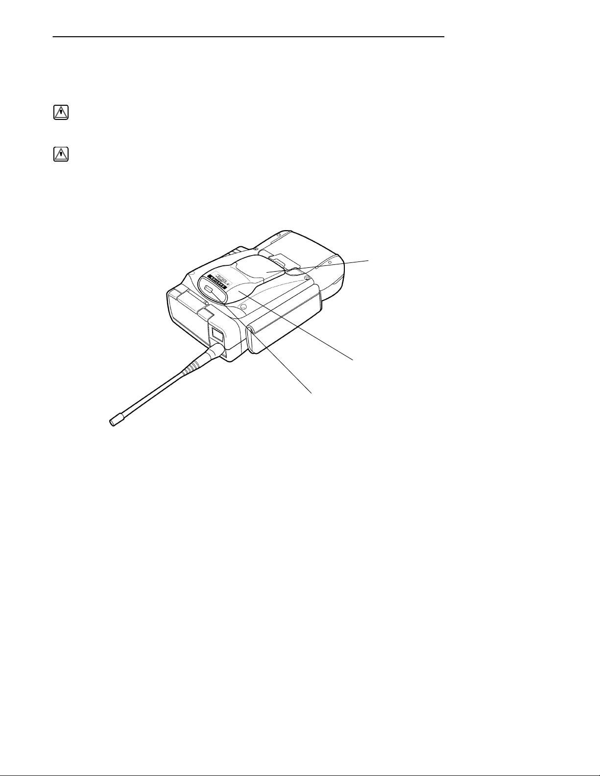
The following descriptions will familiarize you with the
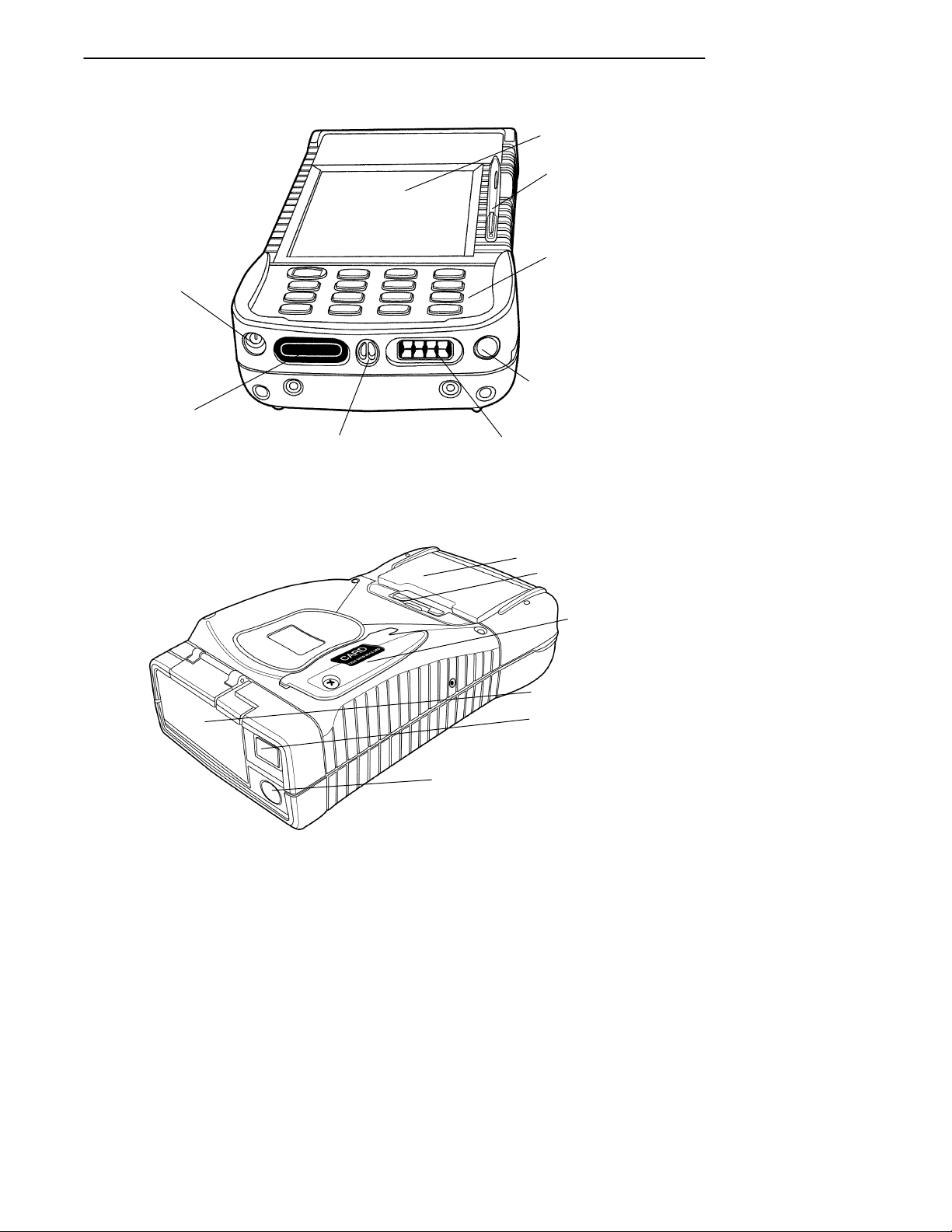
name, function, and locations of the main computer components. Figure 1-1, and Figure 1-2, on pages 1-3, show you
the location for your hand-held computer key components.
1-2 6110 Hand-Held Computer User’s Guide
Page 9
SECTION 1 General Information
Touch Screen
Stylus
DC Power Jack
Infrared (IrDA)
Lens
Speaker
Slot
Figure 1-1
Front View
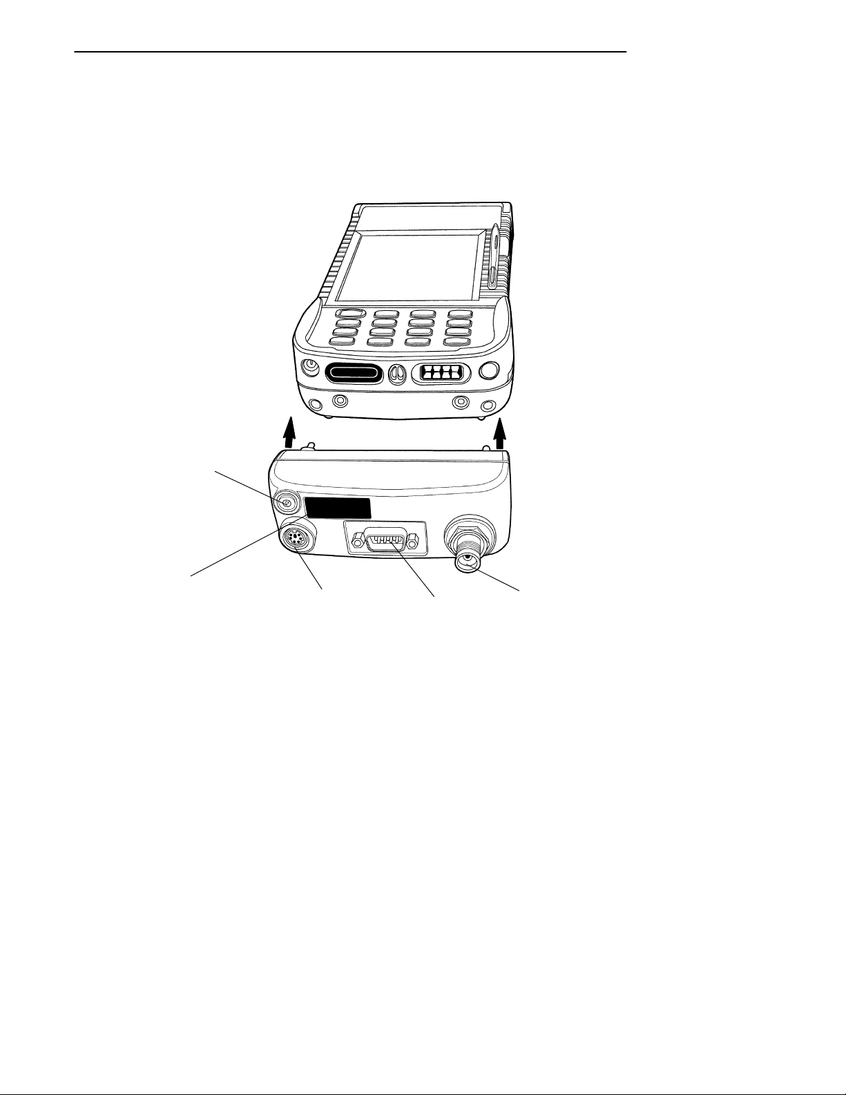
Keypad
Optional External
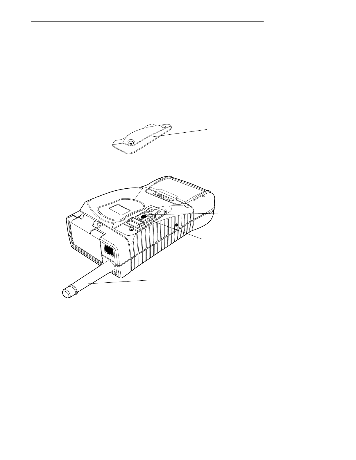
RF Jack
Docking Connector
Battery Pack
Battery Pack Latch
Magnetic
Strip Reader
(optional)
PC Card Door
RJ-45 Jack (optional)
Figure 1-2
Back View
External Antenna Jack or
DEX Connector (optional)
6110 Hand-Held Computer User’s Guide 1-3
Page 10
Hand-Held Computer Keyboard
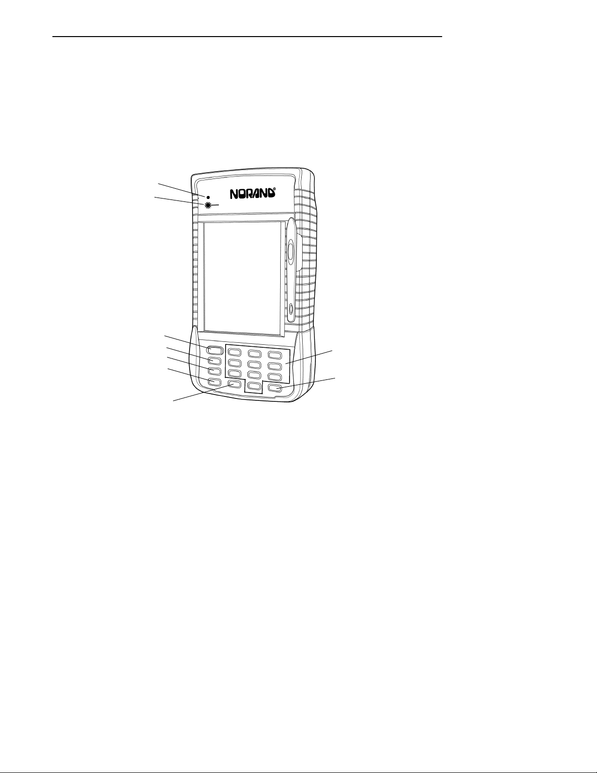
The hand-held computer provides a 16 key keyboard. All
keys with the exception of the I/O key are programmable for
individual functions. Figure 1-3 details the basic keyboard
layout.
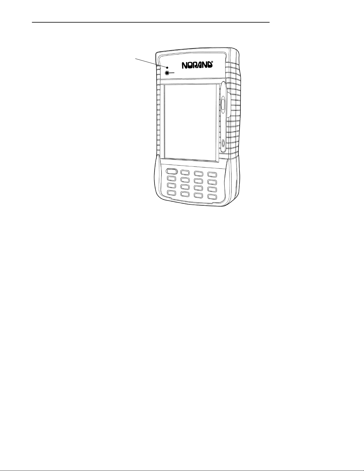
Power Status LED
Scanning Status LED
SECTION 1General Information
I/O (Suspend/Resume) Key
Tab Key
BkSp (Back Space) Key
GOLD (Shift Key)
ESC (Escape) Key
Figure 1-3
16-Key Keyboard
1-4 6110 Hand-Held Computer User’s Guide
Numeric Keys
ENTER Key
Page 11

SECTION 1 General Information
Display
This hand-held computer offers an easy to read Liquid
Crystal Display (LCD) with touch screen. The display
shows status messages, keyed-in entries, customer or product lists, calculations, and prompts for responses. The touch
screen can be used with a stylus, or your finger to choose
functions, record signatures, or enter data.
Adjusting the contrast setting for the display is done by
pressing the gold Shift key and tap either the 1 (increase) or
2 (decrease) key until you achieve the desired level. Of
course, this will depend on if these keys have not been programmed for other functions.
Backlight
Your hand-held computer display and keyboard comes
equipped with a backlight. Backlighting provides a great
benefit in dark conditions.
Backlighting does, however, reduce battery life, therefore,
turn off the backlight when done using.
To turn the backlight on, press the gold Shift key and the 3
key. To turn the backlight off, press gold Shift and the 3 key
again. The amount of time the backlight stays on before
shutting itself off is set and controlled through the Configuration Program.
Battery
"
NOTE: It is important to charge your hand-held computer for at least 14
hours before you use it the first time. This ensures that both the
backup battery and the main battery pack are fully charged.
This hand-held computer uses a 1500 mA hour lithium ion
rechargeable main battery pack. Your hand-held computer
can check battery capacity by various methods. One, the
battery pack has four LEDs that will display remaining ca-
6110 Hand-Held Computer User’s Guide 1-5
Page 12

SECTION 1General Information
pacity when two of the contacts are touched at the same
time. More on this in Section 2 on page 2-9. A second method is to use a software fuel gauge based on the APM 1.1
specification.
If your hand-held computer goes into a shutdown mode because of low battery condition, data is protected by the
backup battery. Your computer contains two 100 mA hour
vanadium lithium backup batteries. The backup battery
charges itself from the main pack or a charging source so it
is constantly ready to take over data protection.
This user’s guide will occasionally use the term “cycles”
when presenting rechargeable battery instructions. Cycles,
are the number of times the rechargeable battery pack can
be charged and discharged during the life of battery. The
Lithium Ion rechargeable battery design, used in the main
pack, should give you approximately 500 cycles of use.
There are no guarantees on this number because it depends
greatly on how the battery pack is used and cared for.
Memory
Three types of memory are available with this computer:
" Main Memory DRAM
" Flash ROM
" PC Cards
Main Memory
Standard main memory DRAM configuration is 8 megabytes (MB), this can be extended to 16, or 32 MBs. Main
memory was ordered at the time your unit was purchased.
You are able to upgrade to a larger memory size by having a
new memory board installed at your Customer Support
Center.
The main memory is protected by the backup battery during low main battery conditions or when the main battery
pack is removed.
1-6 6110 Hand-Held Computer User’s Guide
Page 13

SECTION 1 General Information
Flash ROM
Flash ROM stores the BIOS and BIOS extensions for your
hand-held computer.
PC Cards
Different brands of PC cards can be used in your hand-held
computer. Memory cards are available in a variety of sizes
and types. Check with your Sales Representative or System
Engineer for specific options.
Your computer is equipped with three PC card slots. These
slots can be used with memory cards for storage of data,
much like a floppy disk drive on a PC. These slots can also
be used for modems, radios, hard drives, and other options
as they become available.
Two of the PC card slots are version 2.0 Type II and the
other slot is an ATA card slot. Type III cards can be
installed but you sacrifice slot space. The ATA and two PC
slots have card guides, but the empty bay on top does not.
There is no blockage between any of the slots, so any pair of
Type II bays can accommodate a Type III card.
EXAMPLE: A Type III ATA hard drive card can be installed in the ATA slot, but it
takes up the PC slot B bay space. A Type III PC card installed in slot
B takes up slot B and A; and a Type III PC card installed in slot A
takes up slot A and the empty bay.
6110 Hand-Held Computer User’s Guide 1-7
Page 14
SECTION 1General Information
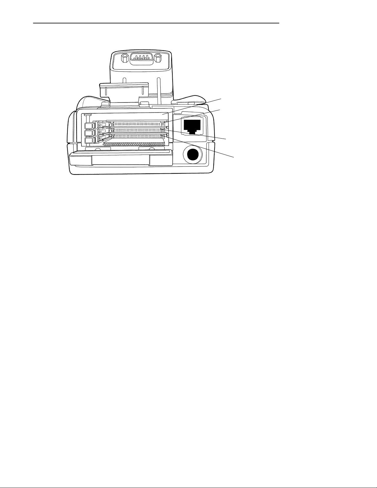
Empty Bay
Slot A (typically
used for a radio
card)
Slot B (typically
used for a modem
card
Slot C (typically
used for a hard
drive card or a
SanDisk flash
ATA card)
Figure 1-4
PC Card Slots
1-8 6110 Hand-Held Computer User’s Guide
Page 15
SECTION 1 General Information
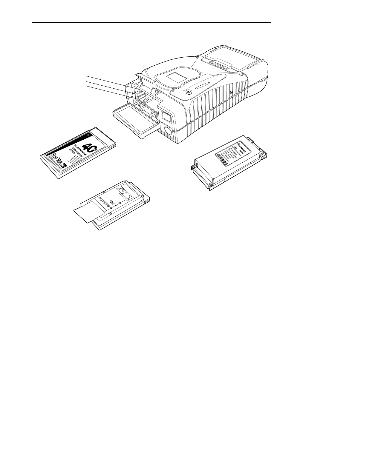
Slot A
Slot B
Slot C
Radio card
Flashdisk or hard drive card
Slot C
Slot A
Modem card
Slot B
Figure 1-5
PC Card Slots
When a card is installed, the top label of the card faces upward (per the orientation shown in Figure 1-5). Slot C (ATA
slot) must always have a mass storage device to serve as
the system disk (C:). This can be a SanDisk flash memory
card or a rotating hard disk drive. The system will not operate without this disk present.
6110 Hand-Held Computer User’s Guide 1-9
Page 16

Slots A and B are true PC card slots, and can accommodate
a variety of pc cards such as modems, radios, or additional
mass storage.
A special factory installed option involves a serial interface
radio card (example: Motorola Series 500 Radio) for use in
slot A. This type of card does not have PC interface, therefore, it cannot be inserted all the way into the connector at
the back of the bay. A special bracket holds the card in
place, and the serial interface is attached via a flex cable.
"
NOTE: Section 2 page 2-11 shows you how to install the PC cards.
[Gold] (Shift) Key
Hold down and press desired gold (shifted) key functions.
Continue to hold down the [GOLD] key for each shifted key
stroke you wish to make.
SECTION 1General Information
[I/O] Suspend and Resume Key
In order to conserve power your hand-held computer may
automatically suspend when there has been no activity for
a set period of time. This time is determined by the configuration program.
To force a suspend, press the key defined as the suspend
key and hold the key down for three seconds. To resume operation, press the [I/O] key. Additionally, pressing the release button on the battery pack door forces a suspend. This
protects against losing data when removing the battery
pack.
1-10 6110 Hand-Held Computer User’s Guide
Page 17

SECTION 1 General Information
Serial Ports
" Optional DB9 pod
" Optional RS-232 subset through the DEX connector.
" Optional RS-232 through RJ-45 jack in top of
computer.
" IrDA partial serial port through IR lens.
Resetting
In the rare event that your hand-held computer fails to respond to your input, it may be necessary to “reset.” To reset
press the Gold (shift), Ctrl, Alt keys at the same time, hold
the keys down for three seconds, and your computer will
reboot.
Options and Accessories
Radio Card
Your hand-held computer can be ordered with a radio card.
Using a radio card allows you to operate in a mobile environment and have real-time interaction with a host computer. The radio card slides into either PC card slot A or B (see
page 2-11 for installation and location detail).
6110 Hand-Held Computer User’s Guide 1-11
Page 18
SECTION 1General Information
Integrated Scanner Pod
WARNING: Do not point the scanner at someone’s eyes or look directly into
it when scanning.
AVERTISSEMENT: Ne regardez pas la fenêtre du scanner lorsque vous effectuez une
scannérisation. Ne pointez jamais le rayon laser vers les yeux de
quelqu’un.
Scanner Trigger
Integrated Scanner Pod
1-12 6110 Hand-Held Computer User’s Guide
Integrated Laser
Scanner Housing
Laser Scanner Lens
Figure 1-6
Page 19
SECTION 1 General Information
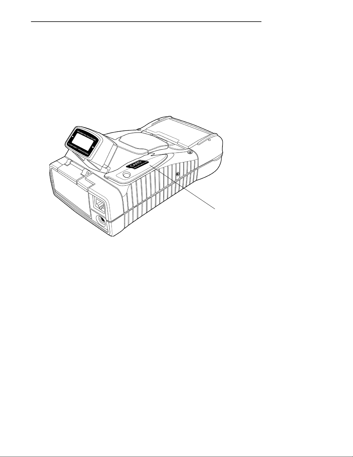
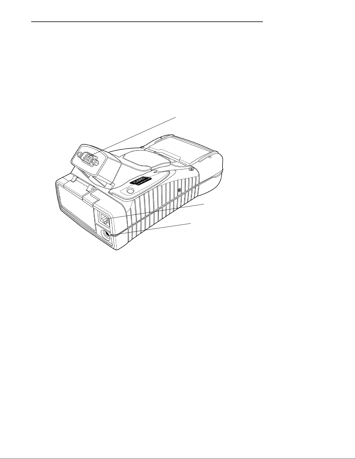
Port Replicator
Slide the Port Replicator onto the computer as shown in
Figure 1-7.
Power Jack (for connecting to
the wall charger or cigar lighter
adapter)
IrDA Port
Keyboard Connector
Figure 1-7
Port Replicator
6110 Hand-Held Computer User’s Guide 1-13
Serial Port
RF Antenna Connector
Page 20
SECTION 1General Information
Magnetic Stripe Reader
The Magnetic Stripe Reader (MSR) is an optional attachment for your hand-held computer. Your MSR reads credit,
charge, and debit (for example, ATM) cards.
Figure 1-8
Magnetic Stripe Reader
1-14 6110 Hand-Held Computer User’s Guide
Magnetic Stripe Reader
Page 21
SECTION 1 General Information
Serial Pod
The serial pod provides a standard 9-pin serial port on a
standard D-sub connector. As a software configuration option, +5 volts of power can be provided on pin 9 (the Ring
pin). This option powers external devices such as tethered
scanners.
9-pin D-sub Serial Port Connector
RJ-45 Jack
External Antenna Jack or
DEX Connector
Figure 1-9
Serial Pod
6110 Hand-Held Computer User’s Guide 1-15
Page 22
SECTION 1General Information
Global Systems for Mobile
Communication (GSM) with
Subscriber Identity Module (SIM)
Allowing access to the SIM allows you to change service
providers and not have to send your unit in for reprogramming.
SIM Cover
Figure 1-10
GSM with SIM card
1-16 6110 Hand-Held Computer User’s Guide
SIM
SIM Socket
Radio Antenna
Page 23

SECTION 1 General Information
Hand-Held Computer Specifications
Size: 8.1 inches (20.57 cm) long
4.3 inches (10.92 cm) wide
2.2 inches (5.59 cm) tall
Temperature:
Operating:
Storage:
Weight: 1 lb. 12 oz. (793.79 g) with battery
Humidity: 5 to 95% noncondensing
Static
Protection: 15 kV (noncontact) 8 kV (contact)
Power source:
Main battery: 7.2 V, 1500 mA hour lithium ion battery pack (standard)
Backup battery: Two 3V, 100 mA hour vanadium lithium battery (standard)
Charging rate:
32 to 140 °F:
(0 to +60 _C)
Communication:
Interface: RS-232, RS-485, and Infrared
Protocol: Norand Proprietary Communications Protocol (NPCP),
14 to +122_F (--10 to +50_C)
--22 to +158_F (--30 to +70_C)
Fast charge (fully charge ¶ 2.5 hours;
95% fully charged ¶ 1.5 hours )
Xmodem, Ymodem, IrDA
6110 Hand-Held Computer User’s Guide 1-17
Page 24

SECTION 1General Information
System Components:
FLASH: 512K FLASH array (standard)
RAM: 8 Megabytes (standard)
16, and 32 Megabytes (optional)
Operating
Win 95
System:
Card Options: One ATA PC card slot for system disk (Type II or Type III
card); plus two PC card slots (two Type II cards, or one Type
II and one Type III card)
Processor: 99 MHz AMD Élan SC400
Display:
Type: Quarter size VGA LCD, CGA Controller, with Backlight
Size: 240 (wide) by 320 (long) pixel, portrait orientation, panning
enables viewing of a full 640 x 480 window.
1-18 6110 Hand-Held Computer User’s Guide
Page 25

Section 2
Operation
" " " " " " " " " " " " " " " " " " " " " " " " " " " "
Introduction
This section tells you how to:
" Install the main battery pack
" “Power-up” your hand-held computer
" Install PC cards
" Connect to peripheral devices
Getting Started
Unpack your Intermec 6110 Hand-Held Computer and inspect it for signs of physical damage from shipment or storage.
When you start using your hand-held computer or any time
that all power has been completely removed, you are “cold
booting” your hand-held computer. The method you use depends on your application.
For example you may download (transfer from the host
computer to your hand-held computer) the application and
data into your computer. Or, you may use PC cards to load
the application and data.
Depending on the method you are using, the result will be
the same but the steps you go through may vary from the
way this user’s guide presents the material.
6110 Hand-Held Computer User’s Guide 2-1
Page 26
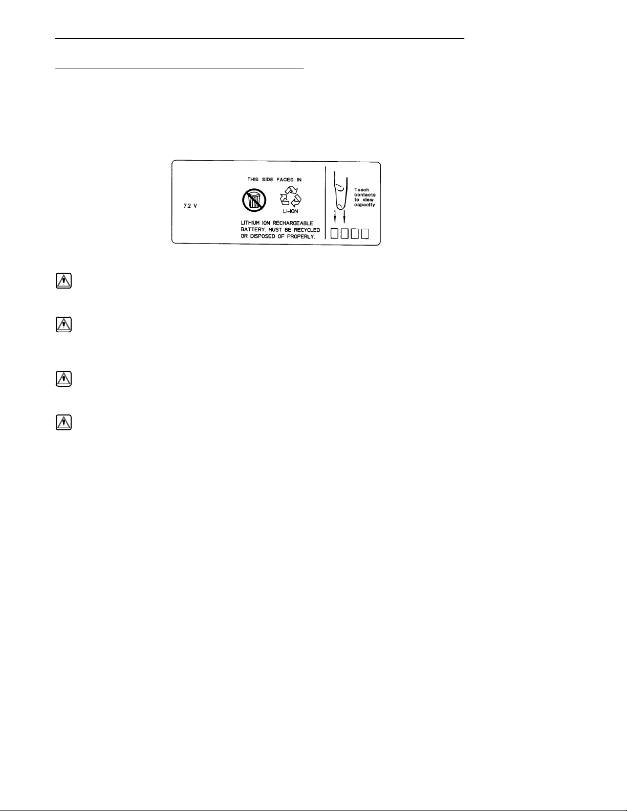
Rechargeable Battery Label
Lithium ION rechargeable batteries must be recycled. This
is the label that appears on the battery pack.
6110 TERMINAL
BATTERY PACK
317-206-001
9742
Made in Japan
CAUTION: Burn hazard,
Do Not Disassemble,
Heat Above 212° F,
Or Incinerate.
WARNING: The lithium ion battery can explode if replaced incorrectly.
Replace the battery with a similar kind.
SECTION 2Operation
AVERTISSEMENT: La batterie au lithium peut exploser si elle est replacée de manière
incorrecte. Elle ne doit être remplacée que par une batterie identique ou
similaire.
WARNING: The lithium battery can explode if placed incorrectly in the
charger.
AVERTISSEMENT: Les batteries au lithium peuvent exploser ou prendre feu si elles
sont trop chargées à cause d’une mauvaise installation de la station
d’accueil.
2-2 6110 Hand-Held Computer User’s Guide
Page 27
SECTION 2 Operation
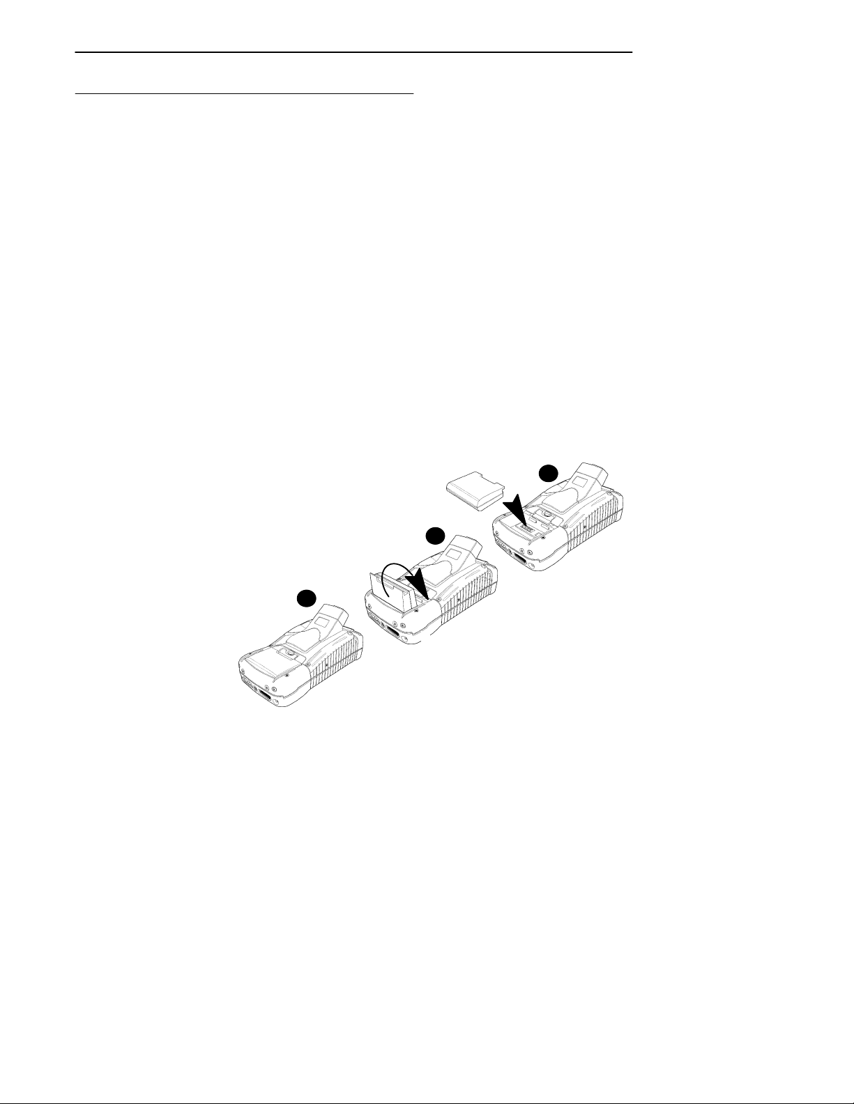
Installing the Main Battery
"
NOTE: Your computer is shipped with uncharged batteries for safety rea-
sons. Refer to Figure 2-1 to show how to install the battery pack in
your computer. Charge your computer for 14 hours before using it
the first time. This will ensure that both the main and backup batteries are fully charged.
1. With the gold battery pack contacts facing into the
battery compartment place the curved portion of the
pack in the bottom of the compartment.
2. Press down on the battery pack until it snaps into
place. As you press down on the battery pack you
should hear three clicks before the pack is completely
seated into place.
"
NOTE: After the initial charging of 14 hours, the normal charge time for the
main battery pack is 2-1/2 hours.
2
3
1
Figure 2 -1
Installing Main Battery Pack
6110 Hand-Held Computer User’s Guide 2-3
1
Page 28

Charging The Batteries
Charging your battery pack can be done either in your
hand-held computer or in a charger. The following devices
provide charge to the batteries while they are connected to
your computer:
In Your Hand-Held Computer
" AC adapter
" Auto adapter
" Single dock
" Multidock
" Vehicle dock
The multidock, single dock, and vehicle dock installation
and instructions are contained in a separate publication
6100 Series Dock Installation Instructions PN:962-020-003.
SECTION 2Operation
2-4 6110 Hand-Held Computer User’s Guide
Page 29
SECTION 2 Operation
Power Status LED
Charging Status:
Blinking Red indicates low battery status
Continuous Red indicates charging in process
Continuous Green indicates charging complete
Blinking Green indicates computer is in standby mode
Off indicates normal operation
Figure 2-2
Power Status LED
6110 Hand-Held Computer User’s Guide 2-5
Page 30
Fuse
SECTION 2Operation
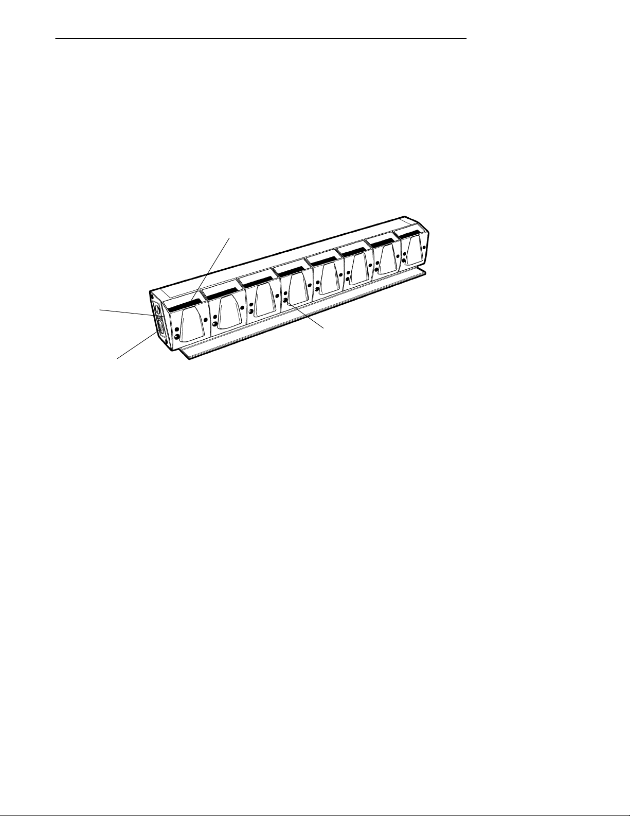
In External Source
When your battery pack is placed in a multipack or single
pack charger, the dock will indicate the charge state (red =
charging; green = fully charged; blinking red = bad battery
or bad connection). Figure 2-3 shows a multipack charger
and Figure 2-4 shows a single pack charger.
Battery Pack Compartments (8)
Power Cord Connector
Multipack Charger
2-6 6110 Hand-Held Computer User’s Guide
Charge Indicator LED (one per compartment)
Figure 2-3
Page 31

SECTION 2 Operation
Power Cord
Battery Pack Compartment
Battery Pack
Contacts
Charge Indicator LED
Figure 2-4
Single Pack Charger
Battery Pack
Contacts
Charge Indicator LED
Battery Pack Compartment
Figure 2-5
SPAN Charger
6110 Hand-Held Computer User’s Guide 2-7
Page 32
SECTION 2Operation
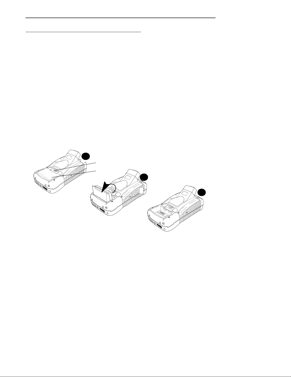
Removing the Main Battery
The following steps on pages 2-8 and 2-9, detail how to
remove the main battery, check how much power the battery contains, and replace the battery pack.
"
NOTE: If you are using Windows 95, ensure that you shut down that opera-
tion before removing the battery pack. Otherwise, your computer will
treat this as a crash.
1. Press and hold down on the Release Button (see
Figure 2-6, Figure 2-7 and pages 2-8, and 2-9, for
battery compartment details). This causes your computer to go into a suspend mode and makes sure you
do not lose your data.
2. Slide the Battery Latch towards the release button
and remove the battery.
1
1
Battery Latch
Battery Pack
Figure 2 -6
Removing the Main Battery Pack
2-8 6110 Hand-Held Computer User’s Guide
2
1
3
Page 33
SECTION 2 Operation
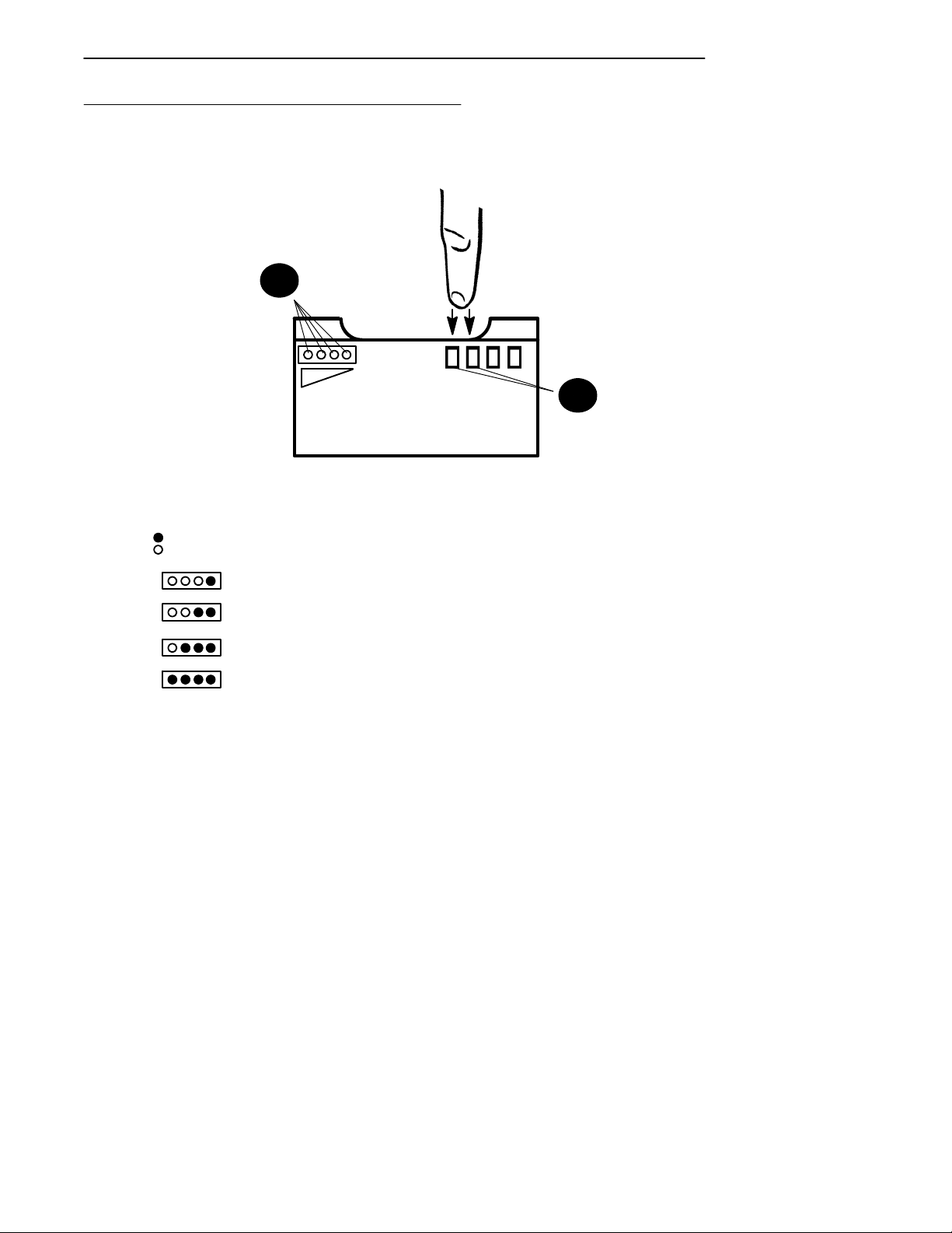
Measuring Battery Pack Capacity
2
1
1. Touch finger across first two contacts
2. Capacity is displayed from right to left.
The higher the capacity the more LEDs light.
= LED on
= LED off
one LED = less than 25% capacity;
two LEDs = 25--50% capacity;
three LEDs = 50--75% capacity;
four LEDs = more than 75%
Figure 2 -7
Main Battery Pack Underside View Showing Contacts
6110 Hand-Held Computer User’s Guide 2-9
Page 34

Backup Battery
This hand-held computer comes with two 100 mA hour vanadium lithium backup batteries. These batteries provide
protection of your data when the main battery is removed
from the hand-held computer or when the main battery
goes into a low battery condition. The backup battery will
not, nor is it intended to, run your application with the
main battery pack run down or removed from your computer.
A fully charged backup battery will provide protection for
maintaining data approximately 2 days with the main battery removed or completely run down.
The backup battery is not user replaceable. To have your
backup battery replaced, send it in to the Customer Service
Center nearest you. Whenever you send in your hand-held
computer for service, include a description of what you
would like to have done.
SECTION 2Operation
Backup Battery Life
The backup battery is rechargeable and will recharge every
time it needs it from either an external charging source or
the main battery pack. If completely run down it will take
at least 14 hours to completely recharge the backup battery.
A frequently run down main battery will not keep the backup battery fully charged.
The backup battery should last approximately 2000 discharge and recharge cycles if deep discharged, maintains
data for 16 hours if your unit has 32 MBs of RAM, and provides service for about 5 years before it needs to be replaced. If your hand-held computer alerts you that the
backup battery needs to be replaced, send it in to the Customer Service Center for replacement.
2-10 6110 Hand-Held Computer User’s Guide
Page 35

SECTION 2 Operation
Using PC Cards to Load Your Programs
Drives
" Drive C:, ATA drive in slot closest to the display
Booting
In order to boot your hand-held computer format on an ATA
PC card with the system files and put it into the slot closest
to the display (Drive C:)
For complete details on creating a “boot” card, refer to the
instructions in the PEN*KEYRModel 6110 Series HandHeld Computer Programmer’s Reference Guide PN:
977-054-001.
BIOS Update
To update the BIOS stored in the flash (6.EXE), obtain the
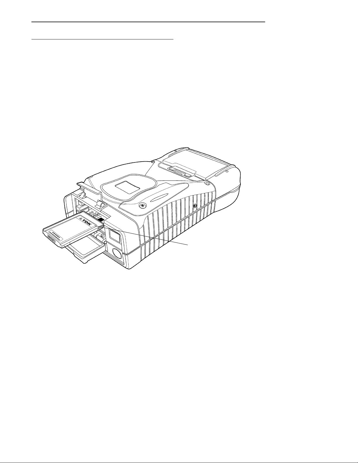
latest from the Intermec web site and execute the BIOS Reflash Program.
Installing PC Cards
1. Lift the PC card door tab and flip open.
2. Slide the cards in one of the slots.
6110 Hand-Held Computer User’s Guide 2-11
Page 36
SECTION 2Operation
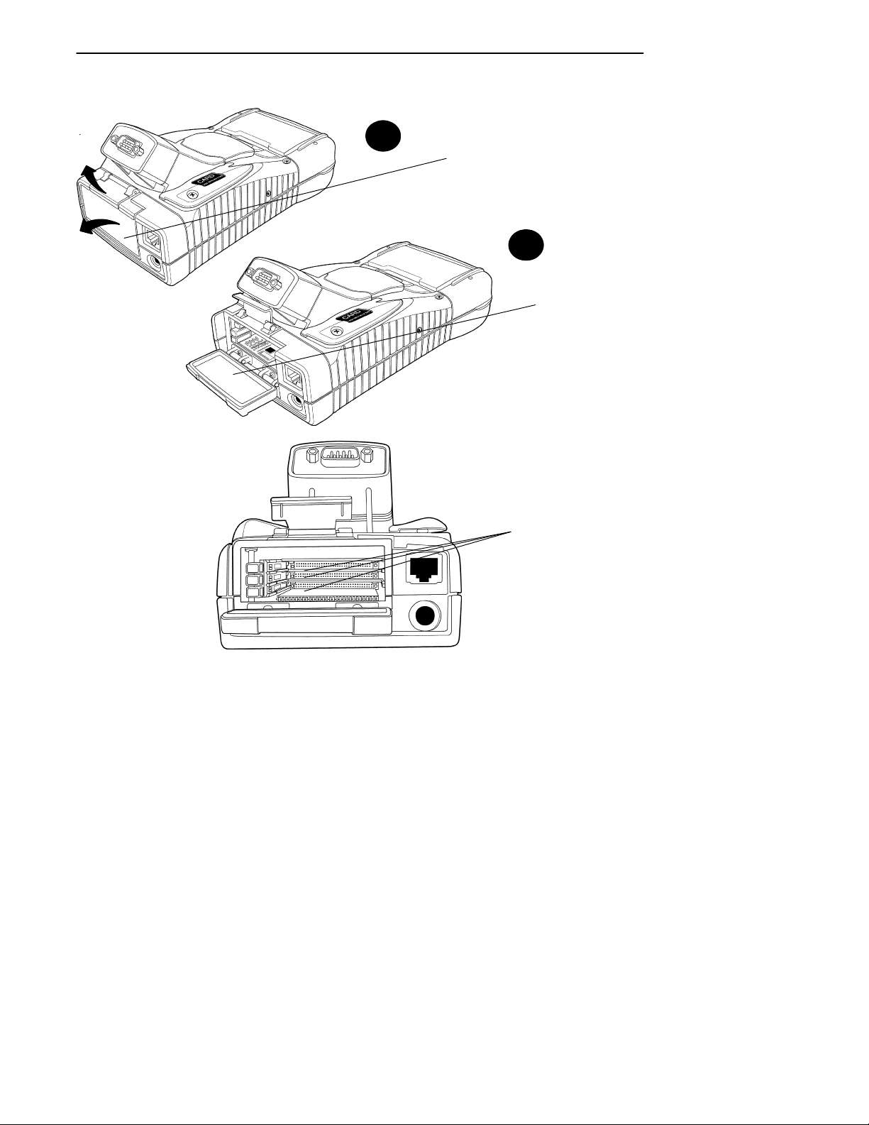
AccessingthePCCardSlots
1
PC Card Slot Door
2
1
Slot Door Open
Figure 2 -8
2-12 6110 Hand-Held Computer User’s Guide
Individual Card Slots
Page 37

SECTION 2 Operation
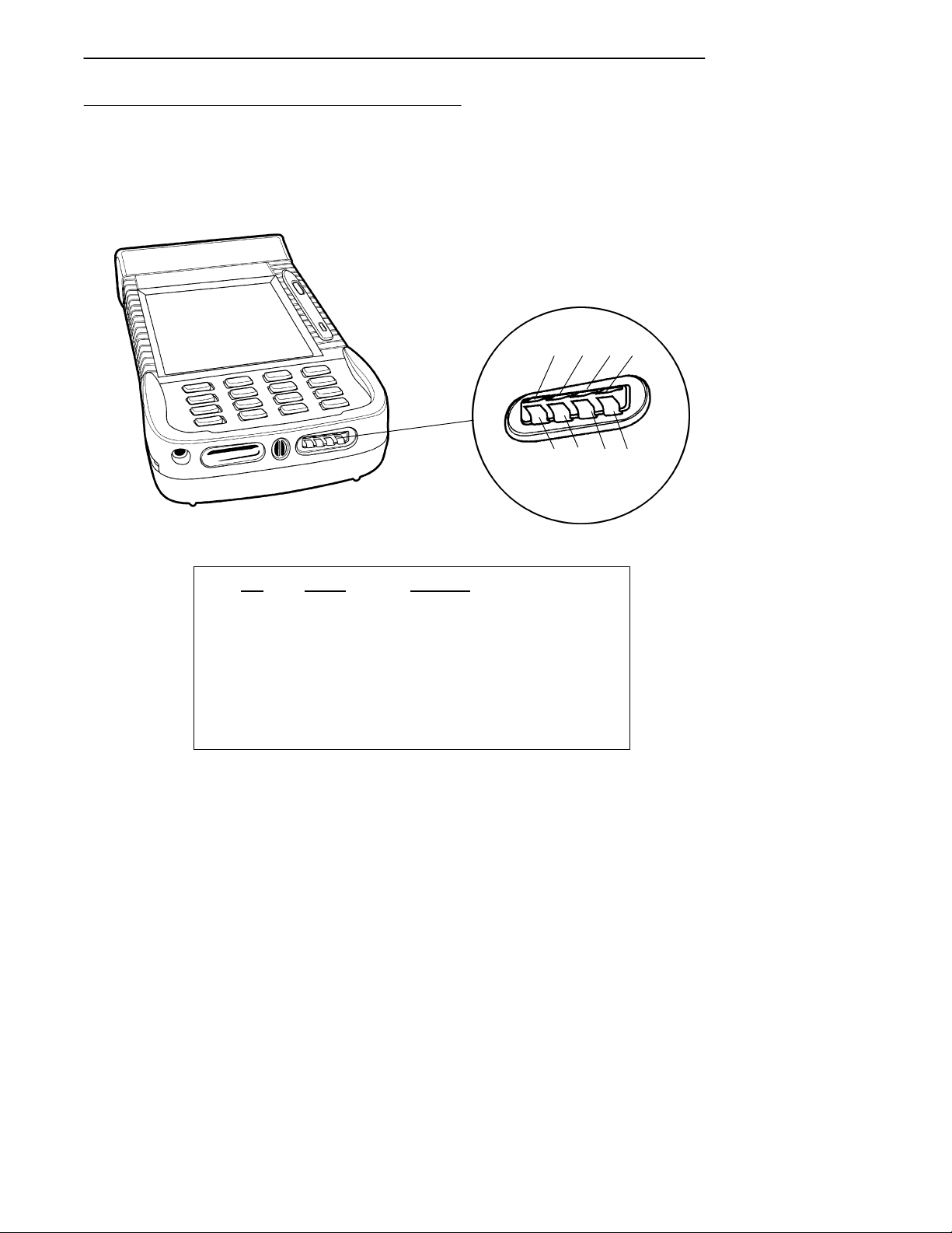
Removing PC Cards
The PC card compartment contains ejector buttons for removing the cards from the slots (see Figure 2-9 for location).
The bottom slot also has a plastic latch called an ATA latch,
which retains the card in the slot. This latch must be
pressed before you can remove the card from the slot. The
latch is to prevent the card which contains the Operating
System from being removed accidentally.
ATA Latch
Individual Slot
Ejector Buttons
Figure 2 -9
Individual PC Card Slot Ejector Buttons
Press in on the ejector button to release and eject the card.
The button will eject the card far enough so you can pull it
the rest of the way with your fingers.
6110 Hand-Held Computer User’s Guide 2-13
Page 38
Installing a Modem Card
The modem card can go into either the top or middle slot
(with your computer in the position shown in Figure 2-10.
However, it you are also going to use a radio card, install
the modem card in the middle slot (B).
To install:
1. Lift the PC card door tab and flip open (see
Figure 2-8).
2. Slide the modem card into slot B (see Figure 2-10).
SECTION 2Operation
Figure 2-10
Installing Modem Card
2-14 6110 Hand-Held Computer User’s Guide
Modem card shown partially
installed in Slot B
Page 39

SECTION 2 Operation
3. Push the modem card all the way into the slot.
4. Line up the modem cable to the connector on the modem card and push into place (see Figure 2-11).
Modem Card Connector
Figure 2-11
Installing Modem Cable
6110 Hand-Held Computer User’s Guide 2-15
Modem Cable
Page 40

SECTION 2Operation
Using the Magnetic Stripe Reader (MSR)
" To use the card reader simply sweep the card through
the reader, in either direction (with the magnetic strip
on the bottom of the card).
Figure 2-12
Using the Magnetic Stripe Reader
2-16 6110 Hand-Held Computer User’s Guide
Page 41

SECTION 2 Operation
Installing the Subscriber Identity Module
(SIM)
1. Remove the SIM cover from the hand-held computer.
Tamper Proof Driver
(p/n 901--136--001)
Phillips Screw
(use #0 bit)
Tamper Proof Screw
Figure 2-13
Removing SIM Socket Cover
6110 Hand-Held Computer User’s Guide 2-17
Page 42

SECTION 2Operation
2. Cut away the SIM from the plastic card.
3. Open the SIM socket by sliding the sleeve forward and
swinging upward.
4. Insert the SIM into the sleeve. Close and secure by
swinging it down and sliding the sleeve back to lock
into place.
5. Reattach the cover.
SIM on cutaway plastic card
SIM
1
2
Figure 2-14
Installing SIM
2-18 6110 Hand-Held Computer User’s Guide
SIM Socket Sleeve
Page 43

Section 3
Routine Care and Maintenance
" " " " " " " " " " " " " " " " " " " " " " " " " " " "
Introduction
Your Intermec 6110 Hand-Held Computer is designed to
withstand normal use in harsh environments. Occasional
maintenance is required to ensure trouble-free operation.
The procedures in this section should help keep your handheld computer in good working condition.
Maintenance procedures included in this section provides
instructions on identifying low battery conditions, and
cleaning your computer.
Low Battery Indication
If you attempt to turn your hand-held computer on and it
does not respond, this usually means the battery is run
down. Just to be sure, insert your computer in a dock or
other charging device, turn it ON, and see if it responds. If
it does, follow the instructions for Charging Your Battery
Pack beginning on page 2-4. If it does not respond when
inserted in the charging source, another problem could exist. Refer to the Troubleshooting section for solutions.
6110 Hand-Held Computer User’s Guide 3-1
Page 44

SECTION 3Routine Care and Maintenance
Cleaning Your Hand-Held Computer
Periodic cleaning helps maintain the appearance and reliability of your hand-held computer. When cleaning your
computer, inspect the keyboard, covers, display, connectors,
and peripheral products for obvious signs of damage or
wear.
B
CAUTION: Do not use any abrasive cleaning compounds, ketonic solvents
(acetone or ketone) or aromatic solvents (toluene or xylene) to
clean any part of your computer. These solutions will cause
permanent damage.
Never pour cleaners directly on the display or the case.
Instead put the cleanser on a soft cloth and gently wipe the
case.
Case and Display
We recommend cleaning the exterior of your hand-held computer using a soft cloth dampened with MICRO-CLEAN II
cleanser, made by Foresight International, Inc. 4887 F
Street, Omaha, NE 68127-0205.
Docking Connectors
If docking connector contacts become dirty or tarnished,
clean them with a cotton swab dipped in alcohol. It may
also be necessary to lightly burnish them with a pencil eraser.
3-2 6110 Hand-Held Computer User’s Guide
Page 45

Section 4
Troubleshooting
" " " " " " " " " " " " " " " " " " " " " " " " " " " "
Introduction
Should you encounter difficulties in routine operation,
printing, or communications, there are a few things you
may be able to do to correct the problem.
" Refer to your applications (software user) manual for
printing and telecommunication procedures.
" Ensure that electrical and mechanical connections are
secure and undamaged.
6110 Hand-Held Computer User’s Guide 4-1
Page 46

Troubleshooting Chart
This Troubleshooting table lists conditions you might see
and offers some basic remedies:
Basic Troubleshooting
Condition Solution
Low Battery Recharge the main battery pack.
Bad TCOM 1. Review and retry communications
procedures.
2. Check cable connections.
Does Not
Respond To
Power
Hand-Held
Computer Will
Not Turn ON
When The [I/O]
Key Is Pressed
As The Battery
Pack Ages It Is
Losing Capacity
and Fewer LEDs
are lighting.
Battery Does Not
Light Any Of The
LEDs
Check to ensure that the dock is
plugged in and hand-held computer
is making good contact.
1. Ensure that there is a main
battery in the computer.
2. The battery door may not be closed
completely.
3. The main battery may be low and
need recharging.
Lithium Ion batteries will lose half of
their available capacity after about
500 cycles (use and recharge = 1
cycle). Therefore, a fully charged
battery pack will show fewer than
four lit LEDs, this is normal. Either
replace the battery pack or plan your
charging needs accordingly, and note
that the capacity will continue to
decrease with each cycle.
1. Charge battery pack then recheck.
2. Replace battery pack if needed.
SECTION 4Troubleshooting
Table 4-1
4-2 6110 Hand-Held Computer User’s Guide
Page 47

SECTION 4 Troubleshooting
Table 4-1 (continued)
Basic Troubleshooting
Condition Solution
Hand-Held
Computer Will
Not Turn ON
When Inserted In
A Printer
The Power
Status LED
Starts Blinking
The printer may be running off
battery power. The printer does not
charge the battery in your computer
when it is running off battery power
itself.
The Power Status LED on the front
panel of your hand-held computer
informs you of the status of your
battery pack when it is connected to
a charging device. The Power Status
LED reads:
Off when in a normal operating
mode;
Blinking red when the battery is low;
Continuous red when charging;
Continuous green when done
charging;
Blinking green when in a standby
mode;
The Charger
Status LED
Starts Blinking
The Charger Status LED on the
external charging device, used for
charging the battery packs, informs
you of the status of the battery pack.
The Charging Status LED reads:
Continuous red for charging;
Continuous green when done
charging;
Blinking red when there is a bad
connection. Lift the pack out and
reseat. If it still blinks call Customer
Service.
6110 Hand-Held Computer User’s Guide 4-3
Page 48

Table 4-1 (continued)
Basic Troubleshooting
Condition Solution
Hand-Held
Computer Will
Not Power Up,
Screen is Blank,
RS-485 Network
Does Not Work
1. Main and Backup Battery are
Critically Low.
2. Ensure that your computer has
been on a charger for at least five
minutes, then remove from the dock
and preform the reset procedure. The
display will then be active.
3. Continue to charge your computer
for at least 14 hours to ensure both
the main and backup batteries are
fully charged. After this initial
charge, the normal time for the main
battery pack to charge is about 2 1/2
hours.
Hand-Held
Computer Will
Not Turn ON
When Placed In
A Dock
Hand-Held
Computer Shuts
Down During
Operation
1. Ensure the dock is plugged in.
2. Ensure that there is a main
battery in your hand-held computer.
3. Ensure the battery door is
completely closed.
1. You may have hit the battery door
latch, this will cause your computer
to suspend. Check the latch.
2. You may have a very low battery,
try recharging the battery.
Hand-Held
Computer Turns
OFF When You
This is the correct operation, the unit
shuts down to conserve energy and
save data.
Open the Battery
Door
SECTION 4Troubleshooting
4-4 6110 Hand-Held Computer User’s Guide
Page 49

SECTION 4 Troubleshooting
Table 4-1 (continued)
Basic Troubleshooting
Condition Solution
Hand-Held
Computer Does
Not Turn OFF
1. May not turn OFF when it is
connected to a charging device.
2. May not turn OFF when it is
processing data.
If either of these conditions continues
for a long period of time, contact our
support personnel as this will run
down the batteries.
Hand-Held
Computer
Displays A Bad
TCOM Message
1. Ensure that full contact is made in
the dock, try reseating computer in
dock.
2. Ensure there is a good connection
between the dock and the host.
Hand-Held
Computer Takes
A Long Time To
Boot Up After A
Normal time is between 30--45
seconds. If longer than this, may
need to contact our support
personnel.
Reset
If these basic solutions do not solve your problem, there
could be a number of reasons. Additional things to do are:
" Refer to the software documentation written for your
application. This documentation contains troubleshooting information.
" Contact the Customer Support Specialist at your Cus-
tomer Service Center. Your regional Customer Service
Center is fully staffed and equipped to repair your
hand-held computer. Customer Support Center addresses and telephone numbers are printed on a Product Service Information card. This document is packed
with all our products.
6110 Hand-Held Computer User’s Guide 4-5
Page 50

Repair Service
Be sure to carefully pack the unit and include a description
of the problem and the measures you took to correct it.
If possible, include any printout (if applicable) or write
down displayed error messages to illustrate the problem.
SECTION 4Troubleshooting
4-6 6110 Hand-Held Computer User’s Guide
Page 51

Appendix A
Connector Pin-Outs
" " " " " " " " " " " " " " " " " " " " " " " " " " " "
6110 Hand-Held Computer User’s Guide A-1
Page 52
8-Pin Docking Connector
APPENDIX AConnector Pin-Outs
2
8
4
1
3
567
Pin Signal Function
1
2
3
4
5
6
7
8
BCLK
12.0 Volts
GND
BDAT
TXD
RXD
RTS
CTS
Figure A-1
Docking Connector Pin-Outs
A-2 6110 Hand-Held Computer User’s Guide
Battery Clock
Power
Ground
Battery Data
Transmit for Serial Port
Receive for Serial Port
Ready To Send for serial port
Clear To Send for serial port
Page 53
APPENDIX A Connector Pin-Outs
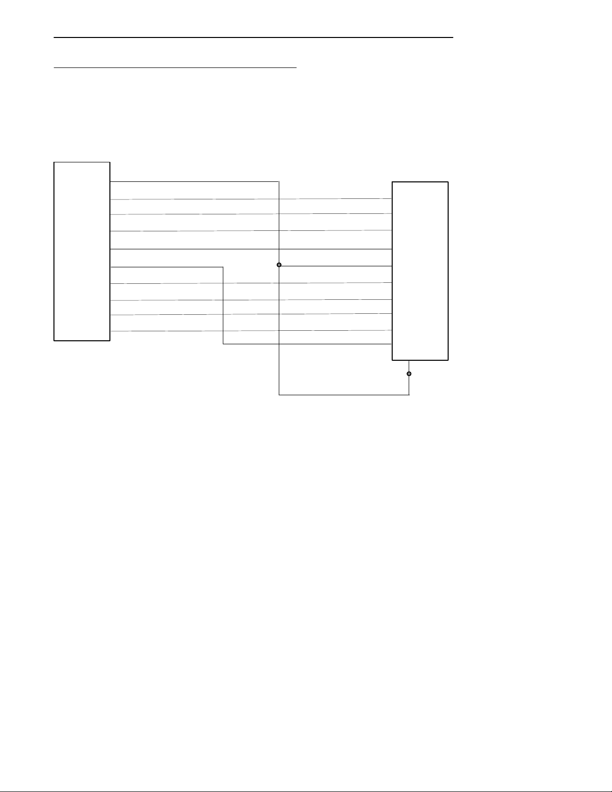
RJ-45 Phone Jack Pin-Outs
J1
Receptacle
10
1
GND
2
DCD
3
RXD
4
TXD
5
DTR
6
PWR
7
DSR
8
RTS
9
CTS
RI
J2
Phone Jack
1
2
3
4
5
6
7
8
9
10
Figure A-2
Phone Jack Pin-Outs
6110 Hand-Held Computer User’s Guide A-3
Page 54

APPENDIX AConnector Pin-Outs
A-4 6110 Hand-Held Computer User’s Guide
Page 55

Appendix B
PEN*KEY
" " " " " " " " " " " " " " " " " " " " " " " " " " " "
The PEN*KEYRUtilities Program provides basic functions
required to prepare your Hand-Held Computers for use.
Utilities Program
Entry Point
PEN*KEY UTILITIES
PSROMOC Vx.xx
R
Screen Title
This screen appears after cold-booting the computer.
" Screen Title: (dark bar at the top) contains the
application name, such as “PEN*KEY UTILITIES”,
and the specific screen name, such as “MODEM
PARAMETERS.”
" Key Description: (dark bar at the bottom) contains
“action” keys. Movement keys, such as arrows, are not
shown.
COPYRIGHT 1994--1999
INTERMEC
TECHNOLOGIES
CORPORATION.
ALL RIGHTS RESERVED
[ENT]CONTINUE
Key Description
Pop-Up Menus
Pop-Up menus appear after a menu option. Press the number of an option you want to select; or press the Y or B
6110 Hand-Held Computer User’s Guide B-1
Page 56

keys to scroll through the list and press the [ENT] key to
enter. Select one option each time.
Press the [ESC] key to exit a pop-up menu.
Drop-Down Lists
APPENDIX BPEN*KEYRUtilities Program
CHANGEUNITID
UNIT ID 2233233
WORKGROUP
6200IPL
[F4]RESET FACTORY
[ESC]QUIT
1. NETWORK. . .
2. MODEM/DIRECT
3. ACCESSORY CARD
4. HANDHELD
5. REMOTE OPS
6. INTERSERVER
Drop-down lists provide suboptions for a pop-up menu.
Press the number of a suboption, or press the Y or B keys
to scroll through the list and press the [ENT] key to enter.
Select one suboption each time.
Press the [ESC] key to exit a drop-down list.
B-2 6110 Hand-Held Computer User’s Guide
Page 57

APPENDIX B PEN*KEYRUtilities Program
Alphanumeric Fields
NETWORK PARAMETERS
SERVER NAME
I.U.N. INCORPORATED
SERVER IP ADDRESS
CLIENT IP ADDRESS
ROUTER
SUBNET MASK
[ESC]QUIT
If your computer has a numeric keyboard, enter alphanumeric data by pressing the A and " keys to scroll back and
forth through the set of alphanumeric characters. After a
character is selected, press the [ENT] key to enter that
character. Press [ENT] again to move to the next field.
123.123.123.123
123.123.123.123
0. 0. 0. 0
0. 0. 0. 0
If your computer has an alphanumeric keyboard, press the
characters, then press the [ENT] key to move to the next
field.
Press [ENT] to save the entries and exit the menu. Press
the [ESC] key to exit without saving the entries.
6110 Hand-Held Computer User’s Guide B-3
Page 58

Title Screen
When you reboot or reset your computer, the Title Screen
appears:
Press the [ENT] key to continue.
APPENDIX BPEN*KEYRUtilities Program
PEN*KEY UTILITIES
PSROMOC Vx.xx
COPYRIGHT 1994--1999
INTERMEC
TECHNOLOGIES
CORPORATION.
ALL RIGHTS RESERVED
[ENT]CONTINUE
B-4 6110 Hand-Held Computer User’s Guide
Page 59

APPENDIX B PEN*KEYRUtilities Program
Language Selection
"
NOTE: The PEN*KEY Utilities Program checks files for available language
options. If no language resource files exist, you do not see this
menu.
If your application requires non-English languages, the
Language Selection menu appears. English is the first option, followed by up to nine additional options:
PEN*KEY UTILITIES
LANGUAGE SELECTION
1. ENGLISH
2.
3.
4.
5.
6.
7.
8.
9.
0.
[ESC]QUIT
Press the number of a language, or press the Y or B keys
to scroll through the list, then press the [ENT] key to enter.
Press the [ESC] key to exit this menu.
6110 Hand-Held Computer User’s Guide B-5
Page 60

APPENDIX BPEN*KEYRUtilities Program
Communications Menu
"
NOTE: The default is the NPCP RS-485 communication.
"
NOTE: If your computer does not support any of the features listed, the fol-
lowing pop-up menu appears. Press the [ENT] key to continue:
COMMUNICATIONS
FEATURE
NOT SUPPORTED
[ENT]CONTINUE
The “Communications Menu” appears after the “Title
Screen:”
PEN*KEY UTILITIES
COMMUNICATIONS
1. BEGIN COMM SESSION
2. COMM SETTING
3. UNIT ID
4. NETWORK PARAMETERS
SERVER NAME
NRINET
9. ADVANCED UTILITIES
B-6 6110 Hand-Held Computer User’s Guide
CLIENT IP ADDRESS
0.0.0.0
ROUTER
0.0.0.0
SUBNET MASK
0.0.0.0
[ESC]QUIT
Page 61

APPENDIX B PEN*KEYRUtilities Program
Option 1 BEGIN COMM SESSION
If you select Option 1, the computer repeats communications until successful or you press the [ESC] key.
"
NOTE: If you press the [ESC] key, this verification window appears:
ARE YOU SURE YOU
WANT TO STOP
COMMUNICATIONS
NOW?
[ENT]STOP
[ESC]RESUME
"
NOTE: This window may not appear immediately. For most communication
settings, a session cannot be interrupted once it has started, so the
[ESC] key is not processed until the next session is attempted.
6110 Hand-Held Computer User’s Guide B-7
Page 62

APPENDIX BPEN*KEYRUtilities Program
BEGIN COMM SESSION with NETWORK
If you select the communications option and Option 2.
COMM SETTINGS is set to NETWORK, this “Commu-
nication Status” menu appears:
PEN*KEY UTILITIES
COMMUNICATIONS
COMM SETTINGS:
NRINET
SERVER NAME
CLIENT IP ADDRESS
ROUTER
SIGNING ON
STATUS: 20
[ESC]STOP COMM
0.0.0.0
0.0.0.0
While SIGNING ON is onscreen, STATUS: may appear
with the status of the attempted connection. Refer to
Session Status on page B-12 for meaning.
Following a successful session, PEN*KEY Utilities executes
the downloaded application. If the necessary program files
are not found, this message window appears:
MISSING SYSTEM
FILES
[ENT]CONTINUE
B-8 6110 Hand-Held Computer User’s Guide
Page 63

APPENDIX B PEN*KEYRUtilities Program
If the session is unsuccessful, LAST SESSION appears with
the failure status, such as “T803.”
PEN*KEY UTILITIES
COMMUNICATIONS
COMM SETTINGS:
NRINET
SERVER NAME
CLIENT IP ADDRESS
ROUTER
SIGNING ON
STATUS: 20
LAST SESSION T803
INVALID HOST NAME
OR IP ADDRESS
[ESC]STOP COMM
0.0.0.0
0.0.0.0
6110 Hand-Held Computer User’s Guide B-9
Page 64

APPENDIX BPEN*KEYRUtilities Program
BEGIN COMM SESSION with MODEM/DIRECT
If you select the communications option and Option 2.
COMM SETTINGS is set to MODEM/DIRECT, this “Com-
munication Status” menu appears:
PEN*KEY UTILITIES
COMMUNICATIONS
COMM SETTINGS:
MODEM/DIRECT
MODEM TYPE
NM2400/NM2400A
PROTOCOL BPS FMT
TTY 2400 8N1
AUTO ANSWER
CONFIGURING
LAST SESSION: T289
NO RESPONSE FROM
MODEM
ESC
[ESC]STOP COMM
"
NOTE: The computer may stay at the “CONFIGURING” screen for about 20
seconds if a modem is not detected.
If the session is unsuccessful, LAST SESSION appears with
the failure status, such as “T289.”
B-10 6110 Hand-Held Computer User’s Guide
Page 65

APPENDIX B PEN*KEYRUtilities Program
BEGIN COMM SESSION with ACCESSORY CARD
If you select the communications option and Option 2.
COMM SETTINGS is set to ACCESSORY CARD, the
system attempts to execute the application from a PC card.
If the “MISSING SYSTEM FILES” message appears, press
the [ENT] key to continue.
BEGIN COMM SESSION with INTERSERVER
If you select the communications option and Option 2.
COMM SETTINGS is set to INTERSERVER, this “Com-
munication Status” menu appears:
Transfer:
Press the [ESC] key to exit this screen.
6110 Hand-Held Computer User’s Guide B-11
Page 66

APPENDIX BPEN*KEYRUtilities Program
Session Status
The first single character code (“T”) is the session status,
which applies to all COMM SETTINGS. There are five statuses possible:
" “G” Good session
" “T” Unexpected end of transmission
" “H” Incorrect file header encountered
" “F” File error encountered
" “L” Telecommunications aborted before first file
header received
The three digit number (“289”) indicates the specific protocol error. These error codes apply when COMM SETTINGS
is set to NPCP RS-485 or NPCP RS-232:
“0” No error
“1” MININET.EXE not installed
“6” User aborted communications by pressing
[ESC]
“11” Invalid parameter specified in control file
"
NOTE: The following values indicate an error returned by MININET.EXE.
100 is added to the error returned by MININET.EXE to avoid conflict
with other defined errors.
“101” Illegal buffer length
“103” Invalid command
“105” Command timed out
“106” Message incomplete
“108” Illegal local session number
“109” No resource available
“110” Session closed
“111” Command canceled
“113” Duplicate name in local name table
“114” Name table is full
“115” Name is deregistered, command complete
“117” Local session table full
“118” Session open rejected
B-12 6110 Hand-Held Computer User’s Guide
Page 67

APPENDIX B PEN*KEYRUtilities Program
“119” Invalid name number
“120” No answer
“121” Name not found
“122” Name in use on remote adapter
“123” Name deleted
“124” Session ended abnormally
“125” Name conflict
“126” Incompatible remote device
“133” Network interface is busy
“134” Too many commands outstanding
“135” Invalid LAN adapter number
“136” Command completed while cancel occurring
“138” Command not valid to cancel
“164”--“179” Unusual network condition
“180”--“354” Adapter malfunction
These error codes apply when COMM SETTINGS is set to
MODEM/DIRECT and PROTOCOL is set to TTY:
“0” No error
“6” [ESC] key pressed, aborting communications
“11” Invalid parameter specified in control file
“23” End of transmission
“101” Line lost
“102” Parity error
“103” Character gap too long
“104” Data loss
“105” Excessive NAKs (negative acknowledgements)
“106” Block count error
“107” Block check error
“108” Block framing error
“109” Control character error
“2xx” Modem error
“xx” Hayes response code, or code defined by
program:
“03” No carrier
“04” Command not recognized
“06” No dial tone
“07” Dialed number is busy
6110 Hand-Held Computer User’s Guide B-13
Page 68

APPENDIX BPEN*KEYRUtilities Program
“08” No answer
“86” Error sending command to
modem
“87” Expected numeric response not
numeric
“88” Invalid response format
“89” No significant response from
modem
“97” COM port disabled by system
due to low battery or removal of
PC card modem.
“98” Unrecognized English response
“99” Memory allocation error
"
NOTE: For response codes not listed above, if you purchased this modem
from the Norand Mobile Systems Division of Intermec Technologies
Corporation, contact Customer Response Center at 800-755-5505
(U.S.A. or Canada) or 425-356-1799.
If this modem is not from the Norand Mobile Systems Division, contact your modem supplier.
These error codes apply when COMM SETTINGS is set to
NOVELL NETWARE:
“0” No error
“6” User aborted communications by pressing
[ESC] key.
“100” Connection to host failed. Verify network
connection, verify that PENKEY login name
exists on host.
“101” Could not access include file. Verify existence
of include file on host.
“102” Could not allocate needed memory.
B-14 6110 Hand-Held Computer User’s Guide
Page 69

APPENDIX B PEN*KEYRUtilities Program
These error codes apply when COMM SETTINGS is set to
NRINET:
“0” No error
“6” User aborted communications by pressing
[ESC] key.
“800” PC TCP/IP kernel is missing.
“801” Invalid client IP address. Make sure the entry
for CLIENT IP ADDRESS is correct, or make
sure the DHCP server is running.
“802” Invalid Service or Service Type, or invalid port
number.
“803” Invalid host name or IP Address. Make sure
the entry for SERVER NAME is correct, and
that the server is running.
“804” Could not create socket. Check all cables and
network connections.
“806” Block sent was incomplete or block received
was incomplete.
“807” Client and server negotiation failed.
“808” Server specified an unsupported block size.
“809” Invalid buffer pointer.
“810” All server connections are already in use. Try
again later.
“811” Timeout while sending data. Connection to
remote machine dropped. Make sure the host
is still running, and check all cables and
network connections.
“812” Timeout while receiving data. Connection to
remote machine dropped. Make sure the host
is still running, and check all cables and
network connections.
“813” An attempt to send data to the server failed
due to a closed connection. Ensure the server
is still running, check all cables and network
connections.
“814” An attempt to receive data from the server
failed due to a closed connection. Ensure the
6110 Hand-Held Computer User’s Guide B-15
Page 70

APPENDIX BPEN*KEYRUtilities Program
server is still running, check all cables and
network connections.
“815” Could not access the network attach
information.
“816” An error occurred reading the network attach
information.
“817” Server did not respond to the connect request.
Ensure the server is still running, check all
cables and network connections.
“818” An error occurred reading the TCP/IP kernel
information.
“935” Operation would block.
“939” Destination address required.
“940” Message too long.
“948” Address already in use.
“950” Network is down.
“951” Network is unreachable.
“952” Network dropped connection or reset.
“954” Connection reset by peer.
“955” No buffer space available.
“960” Connection timed out.
“961” Connection refused.
“962” Too many levels of symbolic links.
“963” File name is too long.
“964” Host is down.
“965” Host is unreachable.
“966” Directory not empty.
B-16 6110 Hand-Held Computer User’s Guide
Page 71

APPENDIX B PEN*KEYRUtilities Program
These error codes apply when COMM SETTINGS is set to
TFTP:
“0” No error.
“1” PSROB0C.EXE could not be loaded.
“6” User aborted communications by pressing
[ESC] key.
“100” TCP/IP kernel is missing.
“101” Invalid client IP address. Ensure the entry for
CLIENT IP ADDRESS is correct or ensure the
DHCP server is running.
“201” TFTP.EXE failed.
“202” TFTP.EXE not found.
“203” Unknown server.
“204” Remote file name is invalid.
“205” Local file name is invalid.
“206” File not found on server.
“207” Timeout.
Option 2 COMM SETTING
If you select this option, the “Communications Settings”
drop-down list appears:
1. NETWORK. . .
2. MODEM/DIRECT
3. ACCESSORY CARD
4. HANDHELD
5. REMOTE OPS
6. INTERSERVER
Press the number of a communications settings, or press
the Y or B keys to scroll through the list, then press the
[ENT] key to enter.
6110 Hand-Held Computer User’s Guide B-17
Page 72

APPENDIX BPEN*KEYRUtilities Program
Suboption 1 NETWORK
If you select this suboption, a drop-down list appears with
various networks:
1. NPCP RS485
2. NPCP RS232
3. NRINET
4. TFTP
5. NOVELL NETWARE
Press the number of a network or press the Y or B keys to
scroll through the list, then press the [ENT] key to enter.
The computer returns to the “Communications Menu” with
the selected network assigned to Option 2. COMM
SETTING. See a sample menu on page B-6.
Press the [ESC] key to exit this drop-down list. The computer takes you to the “Communications Menu.”
B-18 6110 Hand-Held Computer User’s Guide
Page 73

APPENDIX B PEN*KEYRUtilities Program
Suboption 2 MODEM/DIRECT
If you select this suboption, the computer returns to the
Communications Menu with the MODEM/DIRECT option
assigned to Option 2. COMM SETTING:
PEN*KEY UTILITIES
COMMUNICATIONS
1. BEGIN COMM SESSION
2. COMM SETTING
3. UNIT ID
4. MODEM PARAMETERS
MODEM TYPE
PROTOCOL BPS FMT
TTY 2400 8N1
AUTO ANSWER
5. PHONE NUMBER
MODEM/DIRECT
NM2400/NM2400A
ESC
9...131369282
9. ADVANCED UTILITIES
6110 Hand-Held Computer User’s Guide B-19
Page 74

APPENDIX BPEN*KEYRUtilities Program
Suboption 3 ACCESSORY CARD
Suboption 6 INTERSERVER
If you select either of these suboptions, the computer returns to the Communications Menu with ACCESSORY
CARD or INTERSERVER assigned to Option 2. COMM
SETTING.
PEN*KEY UTILITIES
COMMUNICATIONS
1. BEGIN COMM SESSION
2. COMM SETTING
ACCESSORY CARD
3. UNIT ID
9. ADVANCED UTILITIES
Suboption 4 HANDHELD
Suboption 5 REMOTE OPS
These suboptions are not supported at this time.
B-20 6110 Hand-Held Computer User’s Guide
Page 75

APPENDIX B PEN*KEYRUtilities Program
Option 3 UNIT ID
If you select this option, the “Change Unit ID” pop-up menu
appears:
CHANGEUNITID
UNIT ID 2233233
WORKGROUP
6200IPL
[F4]RESET FACTORY
[ESC]QUIT
Enter up to eight characters to change the Unit ID. Use the
[¬SP] key to backspace and use the [CLR] to restore the
previous ID. Press the [ENT] key to save the new ID and
return to the “Communications Settings” menu. Press the
[F4] key to reset the ID to factory default. Press [ESC] to
exit this pop-up menu.
Option 4 NETWORK PARAMETERS
Network Parameters appears as Option 4 when Option 2.
COMM SETTINGS is set to one of these three NETWORK
options: NRINET, TFTP, or NOVELL NETWARE.
6110 Hand-Held Computer User’s Guide B-21
Page 76

APPENDIX BPEN*KEYRUtilities Program
NETWORK PARAMETERS with NRINET or TFTP
If you select this option and Option 2. COMM SETTINGS
is set to NRINET or TFTP, this “Network Parameters” popup menu appears:
NETWORK PARAMETERS
SERVER NAME
SERVER IP ADDRESS
CLIENT IP ADDRESS
ROUTER
SUBNET MASK
[ESC]QUIT
If you have an alphanumeric keyboard, press the characters
to the host name, then press the [ENT] key to save the
entry and move to the next field.
0. 0. 0. 0
0. 0. 0. 0
0. 0. 0. 0
0. 0. 0. 0
If you have a numeric keyboard, use the A and " keys to
scroll back and forth through the given set of alphanumeric
characters. After a character is selected, press the [ENT]
key to enter that character. Press [ENT] again to move to
the next field. Press the Y or B keys to move between
fields.
Press [ENT] to save the entries and exit the “Network Parameters” menu. Press the [ESC] key to exit without saving the entries.
B-22 6110 Hand-Held Computer User’s Guide
Page 77

APPENDIX B PEN*KEYRUtilities Program
NETWORK PARAMETERS with NOVELL NETWARE
If you select this option and Option 2. COMM SETTINGS
is set to NOVELL NETWARE, this frame type drop-down
list appears:
1. 802.2
2. ETHERNET II
3. 802.3 RAW
4. 802.2 W/ SNAP
Press the number of a frame type, or press the Y or B keys
to scroll through the list and press the [ENT] key to enter.
Press the [ESC] key to exit this drop-down list without
changing the frame type.
Option 4 MODEM PARAMETERS
Modem Parameters appears as Option 4 when Option 2.
COMM SETTINGS is set to MODEM/DIRECT.
If you select this option, the “Modem Parameters” pop-up
menu appears.
MODEM PARAMETERS
1. MODEM TYPE
NM2400/NM2400A
2. PROTOCOL TTY
3. BPS RATE 2400
4. DATA FORMAT 8N1
5. AUTO ANSWER ESC
[ESC]DONE
Press the number of a modem parameters option, or press
the Y or B keys to scroll through the list, then press the
[ENT] button to enter.
Suboption 1 MODEM TYPE
If you select this suboption, a drop-down list appears with
supported modem types. Press the Y or B keys to scroll
through the list, then press the [ENT] button to enter.
6110 Hand-Held Computer User’s Guide B-23
Page 78

APPENDIX BPEN*KEYRUtilities Program
" If you select drop-option OTHER EXTERNAL or
OTHER INTERNAL, the “Modem Init String” pop-up
menu appears:
MODEM INIT STRING
ATE0V0Q0&M0&S1&C1&
D2&R/QX0L1
[F2]TEST STRING
[ENT]O ESC]QUIT
a. Enter the initialization string of the modem you are
using. Refer to your modem’s reference manual for
information.
"
NOTE: Use A and " keys on numeric keyboards to scroll the alphanumeric
character set.
"
NOTE: If you leave this menu blank, a string is not saved.
b. Press the [ENT] key to enter the string or press
[ESC] to exit this pop-up menu.
B-24 6110 Hand-Held Computer User’s Guide
Page 79

APPENDIX B PEN*KEYRUtilities Program
"
NOTE: Testing the modem initialization string is optional.
" To test the modem string, do the following:
a. Press the [F2] key. The computer replies with
“PLEASE WAIT” and tests the string:
MODEM INIT STRING
ATE0V0Q0&M0&S1&C1&
D2&R/QX0L1
PLEASE WAIT . . .
[F2]TEST STRING
[ENT]OK [ESC]QUIT
Momentarily, the computer displays the modem’s
response:
MODEM INIT STRING
ATE0V0Q0&M0&S1&C1&
D2&R/QX0L1
RESULT: 97
[F2]TEST STRING
[ENT]OK [ESC]QUIT
"
NOTE: Zero indicates the modem was successfully configured. Any other
value indicates an error. See page B-13 for a list of modem errors.
If you purchased this modem from the Norand Mobile Systems Division, contact Customer Response Center at 800-755-5505 (U.S.A. or
Canada) or 425-356-1799.
If this modem is not from the Norand Mobile Systems Division, contact your modem supplier.
b. Press the [ENT] key to update the modem
initialization string. The computer returns to the
“Modem Parameters” pop-up menu with OTHER
EXTERNAL or OTHER INTERNAL assigned.
6110 Hand-Held Computer User’s Guide B-25
Page 80

Suboption 2 PROTOCOL
If you select this suboption, a drop-down list of available
protocols appears:
1. TTY
"
NOTE: TTY is the only protocol currently supported.
Press the number of a protocol, or press the Y or B keys to
scroll through the list, then press the [ENT] key to enter.
The computer returns to the “Modem Parameters” pop-up
menu with the selected protocol assigned.
Press the [ESC] key to exit this drop-down list.
Suboption 3 BPS RATE
If you select this suboption, the BPS Rate drop-down list
appears with various bits per second (BPS) rates:
APPENDIX BPEN*KEYRUtilities Program
Press the number of a BPS rate, or press the Y or B keys
to scroll through the list, then press the [ENT] key to enter.
The computer returns to the “Modem Parameters” pop-up
menu with the selected BPS rate assigned.
Press the [ESC] key to exit this drop-down list.
B-26 6110 Hand-Held Computer User’s Guide
1. 1200
2. 2400
3. 4800
4. 9600
5. 19200
6. 38400
7. 57600
8. 115200
Page 81

APPENDIX B PEN*KEYRUtilities Program
Suboption 4 DATA FORMAT
If you select this suboption, the “Data Format” drop-down
list appears:
1. 8N1
2. 7E1
Press the number of a data format, or press the Y or B
keys to scroll through the list, then press the [ENT] key to
enter. The computer returns to the “Modem Parameters”
pop-up menu with the selected data format assigned.
Press the [ESC] key to exit this drop-down list.
Suboption 5 AUTO ANSWER
This suboption is not supported at this time.
Option 5 NETWORK INTERFACE
“Network Interface” appears as Option 5 when Option 2.
COMM SETTINGS is set to NRINET, TFTP, or NOVELL
NETWARE.
If you select this option, the “Network Interface” drop-down
list appears:
1. ETHERNET
2. RS485
Press the number of a network interface, or press the Y or
B keys to scroll through the list, then press the [ENT] key
to enter. The computer returns to the “Communications”
menu with the selected network interface assigned.
6110 Hand-Held Computer User’s Guide B-27
Page 82

APPENDIX BPEN*KEYRUtilities Program
Option 5 PHONE NUMBER
Phone Number appears as Option 5 when Option 2. COMM
SETTINGS is set to MODEM/DIRECT.
If you select this option, the “Phone Number” pop-up menu
appears:
PHONE NUMBER
9...13193693282
[ . ]DIALING PAUSE
[ENT]OK [ESC]QUIT
Enter up to 16 characters. Use the [¬SP] key to backspace; use the [CLR] to reset to the previous phone number, and press [.] to insert a dialing pause command (“,”).
Press the [ENT] key to save the new phone number and
return to the “Communications Settings” menu.
Press the [ESC] key to exit this pop-up menu.
B-28 6110 Hand-Held Computer User’s Guide
Page 83

APPENDIX B PEN*KEYRUtilities Program
Option 9 ADVANCED UTILITIES
If you select this option, the “Advanced Utilities” menu appears:
PEN*KEY UTILITIES
ADVANCED UTILITIES
1. SET DATE/TIME
2. BATTERY STATUS
Press the number of an advanced utility option, or press the
Y or B keys to scroll through the list, then press the [ENT]
key to enter.
"
NOTE: Suboption 4 FORMAT RAM CARD appears only if the
FORMAT.COM program is in the PATH.
6110 Hand-Held Computer User’s Guide B-29
Page 84

APPENDIX BPEN*KEYRUtilities Program
Suboption 1 SET DATE/TIME
If you select this suboption, the “Set Date/Time” pop-up
menu appears:
SET DATE/TIME
DATE: 01/20/80
TIME: 23:12:04
[ESC]QUIT
Enter numbers for the month, day, year (1980--2079), hour,
minute, and second (up to 23:59:59). Press the [ENT] key
after each entry. An incorrect entry causes the computer to
default to the initial number. Press the [ESC] key to exit
this pop-up menu.
B-30 6110 Hand-Held Computer User’s Guide
Page 85

Glossary
" " " " " " " " " " " " " " " " " " " " " " " " " " " "
6100
A generic term for the 61XX members of the PEN*KEY
Hand-Held Computer products.
API
Application Program Interface.
Application (ADK)
Computer program used for a particular kind of work. This
term is used interchangeably with “program.”
ASYNC
Asynchronous communications. A method of transmitting
data using an external clocking source (the transmitted
characters are preceded by a start bit and followed by a
stop bit).
ATA Card
A credit-card-sized device, which has been specially
designed to meet the needs of small computers, and can be
inserted and removed from a PC Card slot. In the
PEN*KEY products, it is generally a flash storage card,
modem, radio, etc. (See also: Flash Card, SanDisk,
Spinning Media, or Hardcard)
â
Auto Panning
Baud Rate
The Auto Panning mode causes the display driver to
automatically pan, so the active window remains displayed
inside the viewport. (See also: Pan Border)
The speed at which information can be transferred.
6110 Series Hand-Held Computer User’s Guide Glossary-1
Page 86

GLOSSARY
BISYNC (BInary SYNChronous communications)
A method of transmitting data in which the transmission of
a character is marked by a drop or rise in the signal. An
IBM defined, byte-controlled communications protocol,
using control characters and synchronized transmission of
binary coded data.
Boot Default Drive
The drive from which the computer will boot. By default, it
is the flash drive D: but another drive (RAM drive or card
slot) may be selected.
Bootable ATA
The ability to run the CONFIG.SYS and AUTOEXEC.BAT
from an ATA card. In some older versions of flash, the
CONFIG.SYS from the flash drive had to be run to load the
drivers for the ATA card. With Bootable ATA the
CONFIG.SYS and AUTOEXEC.BAT are run from the ATA
card without loading any drivers.
Bus (network)
The main (multiple access) network cable or line that
connects network stations. Also refers to a network topology
of multiple stations communicating directly with the same
cable with terminators at both ends, like an Ethernet or
token bus.
Button
An object that can be clicked, selected, or unselected in your
windows. Usually an event tree is attached to a button so
that when it is clicked, an action is performed.
CD
Carrier detect.
CD
Compact disk, a removable read-only storage medium.
Channel
Refers to a logical data channel. A port may contain one or
more channels. Data for any given wireless station is
Glossary-2 6110 Series Hand-Held Computer User’s Guide
Page 87

contiguous on a channel. Each of the remote ports on a
controller may contain up to three channels apiece.
Click
Press the primary mouse button to select an object on the
screen with the pointer. Unless reversed for left-handed
operation, the left mouse button is the primary button and
the right mouse button is the secondary button. (See also:
Right Click)
CMOS (Complementary Metal Oxide Semiconductor)
1. Usually refers to the system configuration and real-time
clock information, which is often stored in CMOS memory.
2. The construction method for a type of low-power
computer chip.
Controller
The communication control element of the NORANDâradio
data network. Controls the timing and flow of data
messages between the host computer and the radio
terminals.
GLOSSARY
CPU
Central Processing Unit.
CRC (Customer Response Center)
The Norand Mobile Systems Division of Intermec
Technologies Corporation CRC (technical support),
telephone # 1-800-755-7705.
Email: crc@norand.com If you want to Email a problem
or question to the CRC be sure to include the following
information in your message:
Your name
The company name
The company address
Phone # and Email address where you or the customer can
be contacted
Problem description / Question (be specific)
6110 Series Hand-Held Computer User’s Guide Glossary-3
Page 88

GLOSSARY
Also if the equipment was purchased through a VAR please
include the VAR information
Default Drive
See Boot Default Drive.
Dock
A device in which one or more hand-held computers may be
placed for charging and communication.
DOS (Disk Operating System)
A program or set of programs that tells a disk-based
computer system to schedule and supervise work, manage
computer resources, and operate and control its peripheral
devices.
Double-Click
Press the primary mouse button twice quickly to select an
object with the pointer. Primary is usually the left button.
Download
The transmission of data from a host computer to a mobile
computer.
DSD (Direct Store Delivery)
That section of the grocery industry dealing with products
delivered from a supplier directly to a store, rather than to
some intermediate warehouse or distributor. DSD offers
retailers reduced overhead expenses, but carries as a cost a
loss of inventory control.
DSR (Data Set Ready)
An RS-232 modem interface control signal (sent from the
modem to the DTE on pin 6) that indicates the modem is
connected to the telephone circuit.
DTE (Data Terminal Equipment)
The devices in a category that includes terminals and
computers. Also refers to the interface to users’ equipment
as opposed to the DCE interface to the network.
Glossary-4 6110 Series Hand-Held Computer User’s Guide
Page 89

DTR (Data Terminal Ready)
An RS-232 modem interface control signal (sent from the
DTE to the modem on pin 20) that indicates the DTE is
ready for data transmission and requests the modem be
connected to the circuit.
EAN (European Article Numbering) (Bar Code Symbology)
European Article Numbering Code. A bar code symbology
similar to the UPC symbology except that EAN contains 13
characters and uses the first two to identify a country.
EBCDIC (Extended Binary Coded Decimal Interchange Code)
An 8-bit character code scheme used in IBM environments.
EDI (Electronic Data Interchange)
Specifically EDI Standards. The EDI Standards are a
collective group of standards of different industries used for
exchanging data between computers. All EDI Standards
share certain basic concepts for formatting data. There are
EDI standards covering transportation, warehousing,
grocery retail, general merchandise retail, general business,
and other industries.
GLOSSARY
EEPROM
Electrically Erasable Programmable Read Only Memory.
EIA (Electronics Industries Association)
A United States trade organization that issues its own
standards and contributes to ASNI. Best known for its
development RS-232 and the building wiring standard, 568.
Membership includes US manufacturers.
EOF (End Of File)
A constant following the last data in a file that signals its
end.
EOT
End Of Transmission or End Of Tape.
Ethernet
A general term indicating both 802.3 and DIX Ethernet
(also called Ethernet 2.0). See also: 802.3
6110 Series Hand-Held Computer User’s Guide Glossary-5
Page 90

GLOSSARY
ETX (End Of Text)
A control character used to indicate the conclusion of a
message.
Flash
A technology for nonvolatile memory storage. A special type
of EEPROM that can be erased and reprogrammed.
Flash Card
A memory storage PC Card that meets the ATA standard.
(See also: ATA Card, SanDisk, Spinning Media, or
Hardcard)
FSK (Frequency Shift Keying)
A method of frequency modulation in which a binary “1” is
sent as one frequency and a “0” as another frequency. Used
in modems operating at 1200 bps or slower.
FTP (File Transfer Protocol)
One of the protocols typically included as part of the TCP/IP
suite of protocols supported in most implementations of
TCP/IP. FTP is a TCP/IP-based protocol for transferring
files between different systems.
Function
A collection of declarations and statements returning a
value that can be called by name.
Function Prototype
A function declaration that includes a list of names and
types of formal parameters in the parentheses following the
function name.
Gateway (GW) (SNMP)
In current usage, “gateway” and “application gateway”
refer to translating systems that convert data traveling
from one environment to another.
GPS (Global Positioning System)
The Global Positioning System (GPS) is a satellite based
positioning and navigation system that provides precise
position, velocity, and time information.
Glossary-6 6110 Series Hand-Held Computer User’s Guide
Page 91

GUI (Graphical User Interface)
Provides a graphical representation of the environment
which results in a simpler way to detect problem areas.
Also promotes uniformity in operating management
applications, which means greater management
productivity. An example is Network Manager from SUN
Microsystems.
GUI/PM
Graphical User Interface / Presentation Manager.
Hardcard
A spinning media, or PC Card hard drive that plugs into a
PC Card slot. (See also: ATA Card, Flash Card, SanDisk, or
Spinning Media)
Heap (ADK)
An area of memory set aside for dynamic allocation by a
program.
HHC (Hand-Held Computer)
A generic acronym for a NORAND Hand-Held Computer,
including the 4000 Series (43XX, 44XX, 4500) and the
PEN*KEY or 6000 Series (61XX, 62XX, 63XX, 6400, 65XX,
66XX).
Also the trademark of another company.
GLOSSARY
HHC Remote Port
An ADCCP, TTY, or NPCP port which can connect to HHC
or remote controllers. Data channels on HHC ports are
multiplexed onto the host port.
Hop
Used in vector distance routing. A hop equals one data link.
A path to the final destination on a net is a series of hops
away from the origin.
Host
A customer’s host computer.
A computer that provides services directly to users, such as
the user’s computer. In TCP/IP, an IP addressed device.
6110 Series Hand-Held Computer User’s Guide Glossary-7
Page 92

GLOSSARY
A large computer that serves many users, such as a
minicomputer or mainframe.
Host Address
The part of an internet address that designates which node
on the (sub)network is being addressed. Also called host
number.
Host Computer
A large computer that serves many users, such as a PC,
minicomputer, or mainframe.
Host Controller
A 4980 Controller that is functioning as a host to a
secondary controller.
Host Port (com4980)
A port that can connect to a host or a 4980 Network
Controller.
Host System (com4980)
The Unix system that the COM4980 Package runs on.
Hot Swap
Remove and insert a PC Card without rebooting the unit.
I/0 Key
The power suspend or resume switch on the 6100 Computer
— not the same as the reset button. Suspends or resumes
operation depending on the current state of the computer.
Icon
A symbol on the computer desktop that graphically
represents the purpose or function of an application or file.
IFL Card (Initial Flash Load)
An SRAM card that installs the flash contents on most
PEN*KEY systems.
InfraRed
A method for short-range wireless data communication.
Glossary-8 6110 Series Hand-Held Computer User’s Guide
Page 93

internet
Internet
IR
IrDA
GLOSSARY
While a network, “internet” usually refers to a collection of
networks interconnected with routers. See also: network.
(Note the capital “I”.) The world’s largest internet,
including large national backbone nets (such as MILNET,
NSFNET, and CREN) and many regional and local
networks world-wide. The Internet uses the TCP/IP suite.
Networks with only Email connectivity are not considered
on the Internet.
InfraRed. (see also: IrDA)
A standard for InfraRed communications. An IrDA device
creates a connection between two devices or a device and a
network, without a physical connection, using signals
transmitted in the infrared spectrum.
KB (Kilobyte)
One thousand bytes.
LAN (Local Area Network)
A group of network devices in which each device can
communicate through a wired or wireless link. The wired
link may have several segments joined by repeaters and
bridges. The LAN is characterized by the relatively short
distance it is designed to cover, a high speed of operation,
and relatively low error rates. The geographic scope of
LANs is limited to thousands of feet or closely-spaced
building complexes.
Laser (Light Amplification by Stimulated Emission of Radiation)
A method of scanning that uses a coherent light consisting
of one frequency with high density of energy.
Layer
A modular portion of a stacked protocol that consists of one
or more semi-independent protocols. Each layer builds on
6110 Series Hand-Held Computer User’s Guide Glossary-9
Page 94

GLOSSARY
the layer beneath it and feeds information to the protocols
in the layers above it. TCP/IP has five layers of protocols,
and OSI has seven.
LCD
Liquid Crystal Display.
LLC (Logical Link Control)
The upper portion of the data link layer, defined in the
IEEE 802.2 standard. The LLC layer represents a uniform
interface to the user of the data link service, usually a
network layer.
Local Controller
A controller which is directly connected to a host computer.
A local controller uses either secondary ADCCP or ASYNC
on its host port.
Master Boot Card
See IFL Card
MB (Megabyte)
One million bytes.
Memory Cards
See PC Card
Modem
A communication device that enables a computer to
transmit information over a telephone line.
Modem Baud Rate
The speed of the modem connection. The higher the number
the faster the rate.
Modem Device Name
The name of the communications port, for example: COM1,
AUX2, HOST3, or DIGI4.
Modem Settings
The command strings required by your modem.
Glossary-10 6110 Series Hand-Held Computer User’s Guide
Page 95

MQL (Multi-Quad Lockbox)
Multi-quad lockboxes are used for ADCCP communications
with 121/141 HHCs.
MS-DOS (Microsoft Disk Operating System)
A master control program for 16-bit, Intel-based system.
One of the more common operating systems on PC systems.
NAK (Negative Acknowledgement)
Response to receipt of a corrupted packet of information.
Native Mode (ADK)
A command set for asynchronous communication.
NORAND command set compatible among previous
generations of NORAND RF equipment.
Network
A computer data communications system which
interconnects computer systems at various sites. A network
may include any combination of LANs, MANs, or WANs.
See also: LAN, WAN, internet.
GLOSSARY
(ADK) A computer network or terminals connected by
means of (wires or radio transmissions) using software that
enables them to exchange information.
Network Address (SNMP)
In TCP/IP, the network portion of an IP address. For a class
A network, the network address is the first byte of the IP
address. For a class B network, the network address is the
first two bytes of the IP address. For a class C network, the
network address is the first three bytes of the IP address.
In each case, the remainder is the host address. In the
Internet, assigned network addresses are globally unique.
See also: Internet, IP address, subnet address, host
address.
In NetWare, the unique number assigned to each logical
node of the network.
6110 Series Hand-Held Computer User’s Guide Glossary-11
Page 96

GLOSSARY
NMSD
NORAND Mobile Systems Division of Intermec
Technologies Corporation.
Norlib Tool Kit
A NORAND application tool kit for C/C++ programmers.
DOS based. Includes a large C++ class library. Supports
4000 Series Hand-Held Computers and 61XX, 62XX, 63XX,
and 66XX PEN*KEY Computers
NOS (Network Operating System)
Provides many of the services that are distributed
throughout the network to the various servers. Typically
provides the following services: print, file and database,
messaging, communication, and network management.
NPCP (NORANDââPortable Communications Protocol)
NPCP, a NORAND proprietary protocol, provides session,
network, and datalink services for NORAND HHCs in the
NORAND LAN environment used with printers and data
communications.
NRINET
A NORAND protocol that transfers data over TCP/IP.
NULL
A constant, valued at zero.
Null Modem Baud Rate
The speed of the modem connection.
Null Modem Device Name
The name of the communication port, for example, COM1,
AUX2, HOST3, or DIGI4.
OEM (Original Equipment Manufacturer)
A term that identifies certain hardware vendors who
produce PC hardware for a system built by another
company.
On Key
This key is found on some units. It will not turn the unit
“On” or “Off” but it will suspend/resume operation.
Glossary-12 6110 Series Hand-Held Computer User’s Guide
Page 97

Open Systems
Comprises protocols and components that meet standards
set by industry-accepted governing bodies. The standards
ensure that when new protocols and components are
introduced into an existing system, they will meet the
standards and be able to communicate with the existing
system. The OSI model is the basis for a system to
communicate with any other system. The model is a
framework of standards that create protocol stacks and
applications for networking applications.
Open Wireless LAN Node
Any access point or wireless station that connects to the
network using the 900 MHz or synthesized UHF radio
option.
OS
Operating system.
Pan Border
An invisible border that extends inward from the edges of
the physical display, providing an easy means of panning.
(See also: Auto Panning)
GLOSSARY
PC (Personal Computer)
1. A desktop computer developed by IBM or a clone based
on the same architecture developed by a third party vendor.
2. Sometimes used more generically to refer to other
desktop systems, such as the Apple Macintosh. 3. The
original IBM computer using an Intel 8088 CPU and an
8-bit internal bus.
PC Card
A device that fits in the card slots of an Intermec or other
computer. In some PEN*KEY computers, the smaller type
II card occupies one slot, while a type III card blocks the
second slot. The card may be used for data storage, modem,
printer, wireless, or other purposes.
Generally, PC Card is used in reference to devices, whereas
PCMCIA is a reference to the standard.
6110 Series Hand-Held Computer User’s Guide Glossary-13
Page 98

GLOSSARY
PC Card Icon
An icon located in the System Tray, which indicates a PC
Card is plugged into the PC Card slot. (See also: System
Tray)
PCMCIA (Personal Computer Memory Card International
Association)
An industry group responsible for creation of the standard
for devices (slightly larger than a credit card) for small
computers, such as laptop and hand-held computers.
Formerly, devices were referred to as PCMCIA cards, but
are now generally referred to as PC Cards, while PCMCIA
is a reference to the standard.
PDU (Protocol Data Unit) (SNMP)
An OSI term for “packet.” A data object exchanged by
protocol machines (entities) within a given layer. In TCP/IP,
it defines the type of SNMP message being sent.
Pen
An input device similar in usage to a mouse, but similar in
appearance to a writing instrument.
Pend
Wait for a particular response or event to occur. Used
interchangeably with “wait.”
PEN*KEY
A family of NORAND Hand-Held Computers, also known as
the 6000 Series with touch screen capability. Examples
include: 6100, 6110, 6210, 6300, 6350, 6400, 6500, and
6600 Computers.
PEN*KEY Tool Kits
System-oriented programmer’s tool kits. The current tool
kits support: 6100, 6200/6300 6400, 6600 Computers.
PEN*KEY Utilities
A program that provides the basic functions needed to
prepare the PEN*KEY for use, including program load and
data communications.
Glossary-14 6110 Series Hand-Held Computer User’s Guide
Page 99

PenRight
A third party development environment that allows users
to create DOS or Windows applications by dragging and
dropping. You can visit their web site at:
www.penright.com
Physical Port
Equates to port connector. The 4980 Controller has four
internal physical ports (“A”, “B”, “C”, and “D”). It also has
six connectors (“A”, “B”, “C”, “D”, “LAN1”, and “LAN2”).
Ports “B”, “C”, and “D” are permanently attached to the
15-pin connectors labeled “B”, “C”, and “D” respectively on
the back of the controller. Port “A” is attached to either the
15-pin RS-232 connector labeled “A” or to both of the two
9-pin RS-485 connectors labeled “LAN1” and “LAN2”. Port
“A” is attached to the RS-485 connectors when it is
configured as a LAN port, otherwise it is attached to the
RS-232 connector labeled “A.”
PING (Packet Internet Groper)
A utility program that determines if a TCP/IP connection
exists between a workstation and a server.
GLOSSARY
Pixel
Plug and Play
Polled Protocol
Port
The smallest graphic unit to be displayed on screen.
The combination of BIOS, operating system, and peripheral
device components that provides an environment that
configures itself, thereby avoiding potential hardware
conflicts for the operating system by polling the peripheral
devices, assessing their requirements, and determining and
implementing optimal settings for each device.
A system for multiplexing with more than one radio
terminal by systematically querying each unit for traffic.
The physical hardware communication port.
6110 Series Hand-Held Computer User’s Guide Glossary-15
Page 100

GLOSSARY
(SNMP) Physically, an access point to a computer,
multiplexer device, or network. Logically, a pointer to a
TCP/IP application.
Port Replicator
A device that provides connections for a number of devices,
such as: keyboard, serial peripheral, radio antenna, power,
and IrDA printer.
Portrait Mode
In terms of the display, it has an orientation such that the
information displayed on the screen is viewed in a normal
manner, without rotating the image, resulting in a narrow
display.
POST (Power-On Self-Test)
A set of routines for system diagnostics and configuration
that is run by the BIOS during system initialization.
Programmer’s Reference Guide
The comprehensive repository of information about
PEN*KEY programming. It is usually included with a
PEN*KEY Tool Kit.
Proprietary Systems
Systems where all the component devices, protocols, and
standards are from a single vendor, usually with patent,
trade mark, or copyright protection.
Protocol
A formal description of message formats and the rules
computers must follow to exchange those messages.
Protocol Stack (SNMP)
A modular set of functions, one at each layer of the stack,
that form a network service. Each layer of the stack uses
the services of the module beneath it.
Radio Network
Radio-enabled network devices and communication paths.
A group of fixed-end devices and wireless stations in which
Glossary-16 6110 Series Hand-Held Computer User’s Guide
 Loading...