

Page 1

600 Series Industrial Mobile Computer
USER’S GUIDE
" " " " " " " " " " " " " " " " " " " " " " " " " " " "
PN: 961-054-014
Revision F
August 2001
Page 2

" NOTICE The information contained herein is proprietary and is provided solely for the
purpose of allowing customers to operate and service Intermec manufactured
equipment and is not to be released, reproduced, or used for any other purpose
without written permission of Intermec.
Disclaimer of Warranties. The sample source code included in this document is
presented for reference only. The code does not necessarily represent complete,
tested programs. The code is provided “AS IS WITH ALL FAULTS.” ALL
WARRANTIES ARE EXPRESSLY DISCLAIMED, INCLUDING THE
IMPLIED WARRANTIES OF MERCHANTABILITY AND FITNESS FOR A
PARTICULAR PURPOSE.
Wewelcome your comments concerning this publication. Although every effort has
been made to keep it free of errors, some may occur. When reporting a specific
problem, please describe it briefly and include the book title and part number,as
well as the paragraph or figure number and the page number.
Send your comments to:
Intermec Technologies Corporation
Publications Department
550 Second Street SE
Cedar Rapids, IA 52401
INTERMEC, NORAND, NOR*WARE, and PEN*KEY are registered trademarks
of Intermec Technologies Corporation.
Ó 1999 Intermec Technologies Corporation. All rights reserved.
Acknowledgments
Microclean II is a registered trademark of Foresight International.
Microsoft, MS, and MS-DOS, Windows, Windows 95 and Windows CE are
registered trademarks of Microsoft Corporation.
SanDisk is a trademark of SanDisk Corporation.
Page 3

CONTENTS
" " " " " " " " " " " " " " " " " " " " " " " " " " " "
SECTION 1
General Information
About this User’s Guide 1-1. . . . . . . . . . . . . . . . . . . . . . . . . . . . . .
Industrial Mobile Computer Description 1-2. . . . . . . . . . . . . . .
1-2. . . . . . . . . . . . . . . . . . . . . . . . . . . . . . . . . . . . . . . . . . . . . . . . . . . . .
Computer Keyboard 1-5.. . . . . . . . . . . . . . . . . . . . . . . . . . . . .
Display 1-6. . . . . . . . . . . . . . . . . . . . . . . . . . . . . . . . . . . . . . . . . .
Battery 1-6. . . . . . . . . . . . . . . . . . . . . . . . . . . . . . . . . . . . . . . . . .
Memory 1-7. . . . . . . . . . . . . . . . . . . . . . . . . . . . . . . . . . . . . . . . .
[Gold] Key 1-8. . . . . . . . . . . . . . . . . . . . . . . . . . . . . . . . . . . . . . .
ON/OFF (Suspend and Resume) Key 1-9. . . . . . . . . . . . . . .
Serial Port 1-9. . . . . . . . . . . . . . . . . . . . . . . . . . . . . . . . . . . . . . .
Resetting 1-10. . . . . . . . . . . . . . . . . . . . . . . . . . . . . . . . . . . . . . . .
Customer Response Center and Product Service 1-11. . . . . . . .
Factory Service 1-11. . . . . . . . . . . . . . . . . . . . . . . . . . . . . . . . . .
CRC (Customer Response Center) 1-11. . . . . . . . . . . . . . . . .
Specifications 1-12. . . . . . . . . . . . . . . . . . . . . . . . . . . . . . . . . . . . . . .
SECTION 2 2-1.. . . . . . . . . . . . . . . . . . . . . . . . . . . . . . . . . . . . . . . . .
Operation 2-1. . . . . . . . . . . . . . . . . . . . . . . . . . . . . . . . . . . . . . . . . . .
Getting Started 2-1. . . . . . . . . . . . . . . . . . . . . . . . . . . . . . . . . . . . . .
Charging the Battery 2-2. . . . . . . . . . . . . . . . . . . . . . . . . . . . . . . .
Installing CompactFlash Card 2-4. . . . . . . . . . . . . . . . . . . . . . . .
Removing the CompactFlash Card 2-5. . . . . . . . . . . . . . . . . . . .
Booting Your Computer 2-6. . . . . . . . . . . . . . . . . . . . . . . . . . . . . .
For DOS Applications 2-6. . . . . . . . . . . . . . . . . . . . . . . . . . . .
For Windows CE Applications 2-6. . . . . . . . . . . . . . . . . . . . .
Installing Windows CE Components 2-7. . . . . . . . . . . . . . .
Running Windows CE and the Demo Application 2-8. . . . . . .
For Windows 95 Applications 2-8. . . . . . . . . . . . . . . . . . . . . . . . .
Intermec 600 Series Industrial Mobile Computer User’s Guide i
Page 4

CONTENTS
Panning 2-9. . . . . . . . . . . . . . . . . . . . . . . . . . . . . . . . . . . . . . . . .
Downloading from Host Computer 2-11.. . . . . . . . . . . . . . . . . . .
Opening your Application 2-12. . . . . . . . . . . . . . . . . . . . . . . . . . . .
SECTION 3
Routine Care and Maintenance
Low Battery Indication 3-1. . . . . . . . . . . . . . . . . . . . . . . . . . . . . . .
Cleaning Your Computer 3-2. . . . . . . . . . . . . . . . . . . . . . . . . . . . .
Case and Display 3-2. . . . . . . . . . . . . . . . . . . . . . . . . . . . . . . .
SECTION 4
Troubleshooting
Troubleshooting Table 4-1. . . . . . . . . . . . . . . . . . . . . . . . . . . . . . . .
Related Publications 4-3. . . . . . . . . . . . . . . . . . . . . . . . . . . . . . . . .
Repair Service 4-4. . . . . . . . . . . . . . . . . . . . . . . . . . . . . . . . . . . . . . .
APPENDIX A
Connector Pin-Outs
16-Pin Docking Connector A-1. . . . . . . . . . . . . . . . . . . . . . . . . . . .
APPENDIX B
DOS Utilities Program
Entry Point B-1. . . . . . . . . . . . . . . . . . . . . . . . . . . . . . . . . . . . . . . . .
Pop-Up Menus B-1. . . . . . . . . . . . . . . . . . . . . . . . . . . . . . . . . . . . . .
Drop-Down Lists B-2. . . . . . . . . . . . . . . . . . . . . . . . . . . . . . . . . . . .
Alphanumeric Fields B-3.. . . . . . . . . . . . . . . . . . . . . . . . . . . . . . . .
Title Screen B-4.. . . . . . . . . . . . . . . . . . . . . . . . . . . . . . . . . . . . . . . .
Language Selection B-5. . . . . . . . . . . . . . . . . . . . . . . . . . . . . . . . . .
Communications Menu B-6. . . . . . . . . . . . . . . . . . . . . . . . . . . . . . .
Option 1 BEGIN COMM SESSION B-7. . . . . . . . . . . . . . . .
If using PSROM0C V2.xx: B-17. . . . . . . . . . . . . . . . . . . . . . . .
If using PSROM0C V3.xx: B-17. . . . . . . . . . . . . . . . . . . . . . . .
Option 2 COMM SETTING B-18. . . . . . . . . . . . . . . . . . . . . . .
Option 3 UNIT ID B-22.. . . . . . . . . . . . . . . . . . . . . . . . . . . . . . .
ii Intermec 600 Series Industrial Mobile Computer User’s Guide
Page 5

CONTENTS
Option 4 NETWORK PARAMETERS B-22. . . . . . . . . . . . . .
Option 4 MODEM PARAMETERS B-24. . . . . . . . . . . . . . . . .
Option 5 NETWORK INTERFACE B-28. . . . . . . . . . . . . . . .
Option 5 PHONE NUMBER B-29. . . . . . . . . . . . . . . . . . . . . .
Option 9 ADVANCED UTILITIES B-30. . . . . . . . . . . . . . . . .
FIGURES
Figure 1-1 Front and Back View 1-3. . . . . . . . . . . . . . . . . . . . . .
Figure 1-2 Top, Bottom, and Side View 1-4. . . . . . . . . . . . . . . . .
Figure 1-3 16-Key Keyboard 1-5. . . . . . . . . . . . . . . . . . . . . . . . . .
Figure 1-4 CompactFlash Card Slot 1-8. . . . . . . . . . . . . . . . . . .
Figure 1-5 Resetting your Computer 1-10. . . . . . . . . . . . . . . . . . .
Figure 2-1 Computer Being Connected to a Wall Charger 2-2
Figure 2-2 Power Status LED 2-3. . . . . . . . . . . . . . . . . . . . . . . . .
Figure 2-3 Accessing the CompactFlash Card Slot 2-4. . . . . .
Figure 2-4 Removing CompactFlash Card 2-5. . . . . . . . . . . . . .
TABLES
Table 1-1 Gold Legend Keypad Functions 1-8. . . . . . . . . . . . .
Table 4-1 Basic Troubleshooting 4-1. . . . . . . . . . . . . . . . . . . . . .
GLOSSARY
INDEX
Intermec 600 Series Industrial Mobile Computer User’s Guide iii
Page 6

CONTENTS
iv Intermec 600 Series Industrial Mobile Computer User’s Guide
Page 7

Section 1
General Information
" " " " " " " " " " " " " " " " " " " " " " " " " " " "
About this User’s Guide
Section 1
Contains general information about the components of your
600 Series Industrial Mobile Computer. This includes
telling you how the user guide is organized, a summary of
the sections, and the specifications.
Section 2
Tells you how to prepare for using your computer.
Section 3
Contains routine maintenance information for your
computer. Routine maintenance includes recharging the
battery, and cleaning the computer.
Section 4
Takes you through procedures to use when troubleshooting
your computer. This section does not contain all
troubleshooting that can be done by an authorized
Customer Support Specialist, but does contain information
600 Series Industrial Mobile Computer User’s Guide 1-1
Page 8

SECTION 1General Information
to aid you in determining the level of assistance you may
need.
Appendix A
Pin-outs for the external connectors.
Appendix B
DOS Utilities Program setup screens.
Glossary
Contains definitions to words or phrases used in this user’s
guide.
Index
An alphabetically listing of the subjects and page numbers
contained in this user’s guide.
Industrial Mobile Computer Description
Industrial Mobile Computers are used in the marketplace
to perform a wide variety of tasks. The 600 Series
Industrial Mobile Computer provides features and benefits
that include:
" Rugged design
" Fast data processing
" Touch screen display
" Signature capture
Additionally, your computer has the ability to use:
" CompactFlash cards
1-2 600 Series Industrial Mobile Computer User’s Guide
Page 9

SECTION 1 General Information
" Internal modem with CompactFlash card size and for-
mat
The following descriptions will familiarize you with the
name, function, and locations of the components.
Figure 1-1, and Figure 1-2, on pages 1-3, and 1-4, show
you these key components.
Touch screen
display
Stylus
Keypad
Power
status
Scan indicator
Front Back
Figure 1-1
Front and Back View
600 Series Industrial Mobile Computer User’s Guide 1-3
Page 10
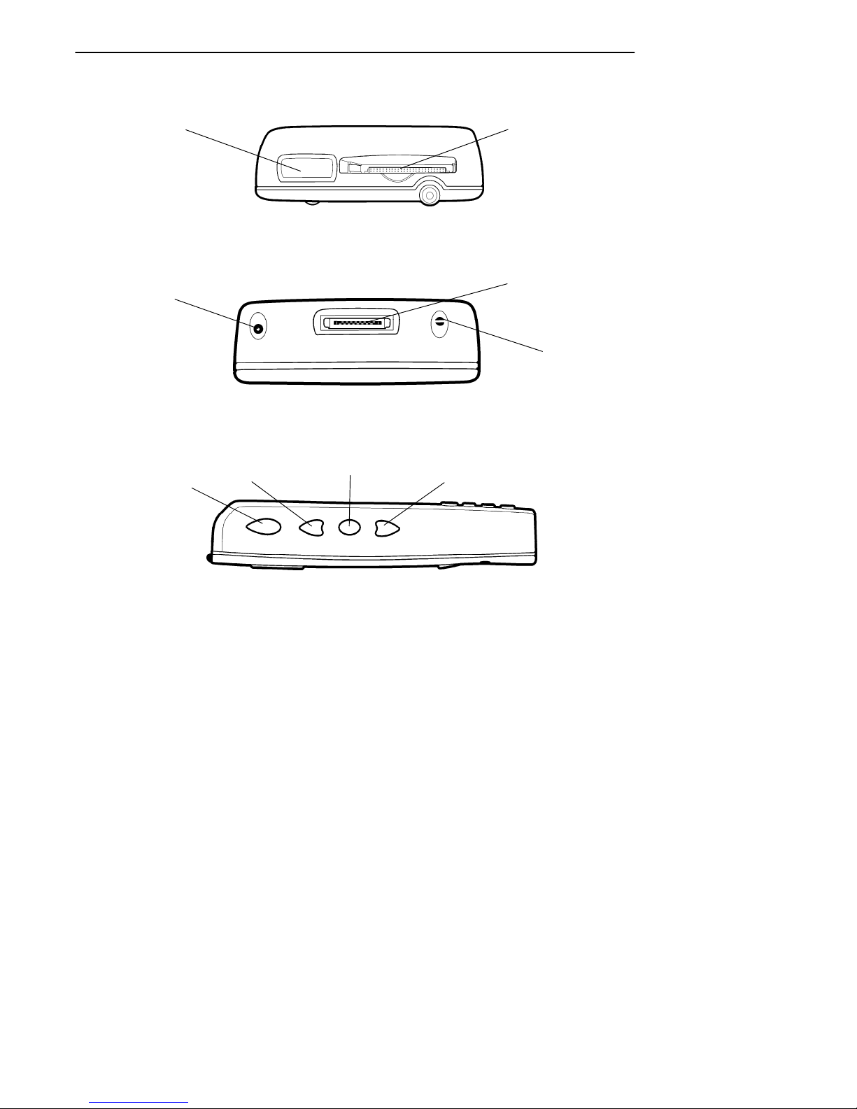
SECTION 1General Information
Scanner lens
(optional)
Charger
jack
Scanner
button
Scroll up key
Top End
Bottom End
Action key
CompactFlash
card slot
Docking
connector
Speaker
Scroll down
key
Side View
Figure 1-2
Top, Bottom, and Side View
1-4 600 Series Industrial Mobile Computer User’s Guide
Page 11

SECTION 1 General Information
Computer Keyboard
This Industrial Mobile Computer provides a 16 key
keyboard. All keys with the exception of the [I/O] and
[Gold] keys are programmable for individual functions.
Figure 1-3 on page 1-5 details the basic keyboard layout.
ON/OFF
(Suspend/Resume)
Tab
BkSp (Back Space)
Numeric
keys
Backlight
(Gold + 3)
ENTER
Gold
Esc (Escape)
Figure 1-3
16-Key Keyboard
600 Series Industrial Mobile Computer User’s Guide 1-5
Page 12

SECTION 1General Information
Display
This Industrial Mobile Computer offers an easy to read
Liquid Crystal Display (LCD) with touch screen. The
display shows status messages, keyed-in entries, customer
or product lists, calculations, and prompts for responses.
The touch screen can be used with a stylus, or your finger
to choose functions, record signatures, or enter data.
Adjust Contrast
To adjust the display contrast level, hold down the [Gold]
key and press either to increase to decrease.
Backlight
Your Industrial Mobile Computer display features a
backlight. Backlighting provides a great benefit in dark
conditions. Backlighting does, however, reduce battery life,
therefore, turn off the backlight when not needed.
Backlight On/Off
To turn the backlight on, hold down the [Gold] key and
press the key. To turn the backlight off, hold down
the [Gold] and press the key again.
Battery
"
NOTE: It is important to charge your Industrial Mobile Computer for at least
4 hours before you use it the first time.
This Industrial Mobile Computer uses a 1550 mAh lithium
ion rechargeable battery.
If your computer goes into a shutdown mode because of low
battery condition, your computer will not operate. Your
computer does this to ensure that the data is protected.
1-6 600 Series Industrial Mobile Computer User’s Guide
Page 13

SECTION 1 General Information
Although the battery will protect the data against loss for
up to 72 hours, it is best to put your unit on a charging
source when you first detect low battery.
Memory
Three types of memory are available with this Industrial
Mobile Computer:
" Main Memory DRAM
" Flash ROM
" CompactFlash Cards
Main Memory
Standard main memory DRAM configuration is 16
megabytes (MB) with an available option of 32 MB. Memory
and the real time clock is protected up to 72 hours by your
computer shutting down operation after detecting low
battery.
Flash ROM
The 512K Flash ROM stores the BIOS. Flash ROM cannot
be used for storage of customer applications or data files.
CompactFlash Cards
Your Industrial Mobile Computer employs an internal card
slot. The internal slot is a CompactFlash Type I storage
device. This device acts as the boot drive for the system.
This CompactFlash card is not externally accessible.
Your 600 Series provides an optional external card slot. The
external slot is a CompactFlash Type II slot that is
accessible at the top of your computer. It can be used for an
additional CompactFlash storage card, or a CompactFlash
modem. If part of the modem extends beyond the top of the
unit it becomes vulnerable to breakage if dropped. Removal
of the device is recommended between communication.
Additionally, most CompactFlash modem devices are not
600 Series Industrial Mobile Computer User’s Guide 1-7
Page 14
SECTION 1General Information
power management friendly so battery life may be
negatively effected. Intermec also offers the mini-land line
modem which connects to the 600 Series via the docking
connector.
Card slot
Figure 1-4
CompactFlash Card Slot
[Gold] Key
Hold down and press desired gold key functions. Continue
to hold down the [Gold] key for each gold legend key stroke
you wish to make.
Gold Legend Keypad Functions
Holding down the [Gold] Key and then a gold legend key
allows additional keypad functions. These functions are
described in Table 1-1 on page 1-8.
Table 1-1
Gold Legend Keypad Functions
Gold + Icon Result
1 Increases display screen contrast
2 Decreases display screen contrast
1-8 600 Series Industrial Mobile Computer User’s Guide
Page 15

SECTION 1 General Information
Table 1-1 (continued)
Gold Legend Keypad Functions
Gold + ResultIcon
3 Toggles Backlight on and off
Tab Home
4 Pg Up Page Up
5
6 Pg Dn Page Down
DEL . (period)
7
8
9
ESC Alt
0 Ctrl (control)
Enter End
Y
A
B
"
Up arrow
Left arrow
Down arrow
Right arrow
ON/OFF (Suspend and Resume)
Key
In order to conserve power your Industrial Mobile
Computer may automatically suspend when there has been
no activity for a set period of time. The suspend time can be
programmed through the setup parameters for your
computer.
To force a suspend, press the [I/O] key, or a key that may be
defined as the suspend key, and hold the key down for three
seconds. Toresume operation, press the [I/O] key. To achieve
maximum battery life force suspend is recommended.
Serial Port
Your computer can access serial devices through the dock’s
RS-232 serial port, using one of these accessories:
600 Series Industrial Mobile Computer User’s Guide 1-9
Page 16

SECTION 1General Information
" A serial cable plugs into and latches to the docking
connector and provides a standard PC compatible
DB-9 (male) serial port.
" A data sychronous cable plugs into and latches to the
docking connector and provides a DB-9 (female) which
can be plugged into a standard PC serial port.
" The 600 Series Single/Vehicle Dock provides a stan-
dard PC compatible DB-9 (male) serial port.
" The 600 Series Multidock converts the signals from
the computer’s RS-232 serial port to RS-485 and
brings out an RS-485 bus to two DB-9 female connectors compatible with Norand RS-485 networking.
Resetting
In the rare event that your Industrial Mobile Computer
fails to respond to your input, it may be necessary to
“reset.” To reset press the [Gold], [Esc], and [0] keys at the
same time, hold the keys down for three seconds, and your
computer will reboot. Resetting takes you to the start up
screen.
Reset keys
Figure 1-5
Resetting your Computer
1-10 600 Series Industrial Mobile Computer User’s Guide
Page 17

SECTION 1 General Information
Customer Response Center and Product
Service
Factory Service
If your unit is faulty, you can ship it to your nearest
authorized Service Center for factory-quality service. The
address and telephone number are included on the Product
Service Information Card shipped with your product.
CRC (Customer Response Center)
Intermec Technologies Corporation CRC (technical
support), telephone number: 1-800-755-5505 (USA or
Canada) or 1-425-356-1799.
Email: support@intermec.com If you want to Email a
problem or question to the CRC be sure to include the
following information in your message:
Your name
The company name
The company address
Phone number and Email address where you or the
customer can be contacted
Problem description or questions (be specific)
Also if the equipment was purchased through a VAR please
include the VAR information
600 Series Industrial Mobile Computer User’s Guide 1-11
Page 18

Specifications
Size: 9.1 cm (3.6 inches) wide
15.5 cm (6.1 inches) long
3.0 cm (1.2 inches) tall
Temperature:
Recommended Operating:
Extreme Operating:
Storage Temperature:
Weight: 312 g (11 ounces.)
Humidity: 5 to 95% noncondensing
Static Protection: 17 kV (air discharge) 8 kV (current injection)
Battery: 3.8 V, 1550 mAh lithium ion battery
Hours of Operation: 8--10 hours
Charging Temperature:
Communication:
Interface: RS-232, RS-485, Ethernet 10BASE-T (through
Protocol: Norand Proprietary Communications Protocol
System Components:
FLASH: 512K FLASH array (standard)
RAM: 16 or 32 MB
Operating System: MS--DOS, Windows CE, and Windows 95
Card Options: CompactFlash Type II
Display: 953 cm (3.75 inches); 240 (wide) 320 (long)
0 to +50_C (32 to +122_F)
--20 to +60_C (--4 to +140_F)
--20 to +60_C (--4 to +140_F)
0 to +50_C (32 to +122_F)
Dock)
(NPCP), TCP/IP
pixels, monochrome LCD
SECTION 1General Information
1-12 600 Series Industrial Mobile Computer User’s Guide
Page 19

Section 2
Operation
" " " " " " " " " " " " " " " " " " " " " " " " " " " "
This section tells you how to:
" Charge the battery
" Power-up your 600 Series Industrial Mobile Computer
" Install CompactFlash cards
Getting Started
Unpack your 600 Series Industrial Mobile Computer and
inspect it for signs of physical damage from shipment or
storage.
When you start using your computer or any time that all
power has been completely removed, you are “cold booting”
it. The method you use depends on your application.
For example you may download the application and data
into your computer. Or, you may use CompactFlash cards to
load the application and data.
Depending on the method you are using, the result will be
the same but the steps you go through may vary from the
way this user’s guide presents the material.
600 Series Industrial Mobile Computer User’s Guide 2-1
Page 20

Charging the Battery
Charging your battery pack can be done either in a dock or
using an ac wall charger connected to your computer.
Figure 2-1 on page 2-2 shows your computer being
connected to an ac charger. Figure 2-2 on page 2-3 shows
the computer and explains the Power Status conditions that
you might see during the charging process.
Normal time to recharge your battery pack is four hours.
When your battery is fully charged your computer should
run about 8--10 hours.
SECTION 2Operation
1
Figure 2-1
Computer Being Connected to a Wall Charger
The following devices charge the battery when seated in
the unit.
" Single/Vehicle dock
" Multidock
2-2 600 Series Industrial Mobile Computer User’s Guide
2
Page 21

SECTION 2 Operation
Power Status LED
Power Status:
Blinking Red indicates low battery status
Continuous Red indicates charging in process
Continuous Green indicates charging complete
Blinking Green indicates computer is in standby mode
Off indicates normal operation
Figure 2-2
Power Status LED
600 Series Industrial Mobile Computer User’s Guide 2-3
Page 22

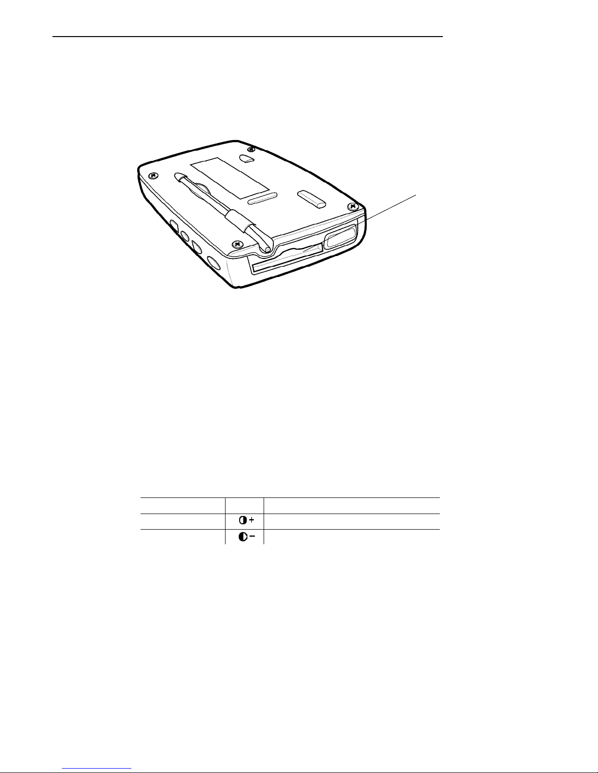
Installing CompactFlash Card
1. Gently apply pressure as you guide the card downward into the card slot.
2. Press at the top end of the card to “set” the bottom end
of the card in the pin connector at the bottom of the
card slot.
3. Gradually relax the pressure but still gently press the
card into place until it is fully seated down in the card
slot.
CompactFlash card Wide channel
SECTION 2Operation
Accessing the CompactFlash Card Slot
2-4 600 Series Industrial Mobile Computer User’s Guide
Figure 2-3
Page 23

SECTION 2 Operation
Removing the CompactFlash Card
Use the tip of your stylus, inserted in the slot and under the
edge on the CompactFlash card, to slide the card out
enough to get ahold of it and pull straight out on the card
slot. Intermec also offers self-adhesive pull tabs (p/n
806-896-001) to help with removal of CF cards.
1 2
Stylus slot
3
Figure 2-4
Removing CompactFlash Card
600 Series Industrial Mobile Computer User’s Guide 2-5
Page 24

Booting Your Computer
For DOS Applications
1. Apply power by pressing the [I/O] (Resume/Suspend)
key or pressing the reset keys ([Gold], [Esc], [0])
simultaneously and holding for three seconds. The
Power Status LED will light.
2. The default load on the card displays these choices:
1. NorandRUtilities
2. DOS Command Prompt. Making this choice puts
you to the DOS prompt 600 C:\>.
3. If you do not make a choice within 10 seconds, your
600 Series computer automatically boots to the
NorandRUtilities. From the Utilities Programs, assuming you have the appropriate host software and
hardware, you can setup the communication options
and also download your application.
SECTION 2Operation
For Windows CE Applications
The following steps outline the initial boot and Windows CE
load on the 600 Series Computer.
1. The AT BIOS loads the boot sector from the IDE drive.
2. After NK.BIN (Windows CE memory image) is loaded
and executed, Windows CE is in control of the system.
From this point, only Windows CE functions are accessible to application developers for the 602 Computer.
3. TASKMAN.EXE (the Windows CE shell program) is
executed by Windows CE. The first time CE is executed, “Task Manager” performs pen calibration and
writes the calibration results to the registry. The registry is then flushed to persistent storage.
2-6 600 Series Industrial Mobile Computer User’s Guide
Page 25

SECTION 2 Operation
“Task Manager,” then searches for the
“\Storage Card\Wince\WCESTART.INI” file. If the
file is found, the contents of the file are parsed for any
user application to launch and execute. If no application is found, “Task Manager” allows manual browsing
of the files system and execution of programs.
Installing Windows CE
Components
This section outlines the Windows CE release installation
for the 600 Series Computer. The installation includes a
demo application.
Reflashing the 600 Series Computer installs the most
current System Management Interface (SMI BIOS) for the
600 Series Computer and erases the current registry for
Windows CE that is stored in flash memory. Erasing the
registry allows the system to use registry changes
incorporated in the new Windows CE release.
"
NOTE: Upgrading flash erases the registry and destroys previous settings.
Perform the following steps:
1. Copy 600FLSH.BIN to computer or put on external
card.
2. Start up CE, then select Start, then Settings, then
Control Panel.
3. Select the icon for the Intermect Utilities.
4. Select the BIOS UPGRADE tab then press the button [...] to bring up the standard browse window.
5. Double tap on 600FLSH.BIN
6. Press the UPGRADE button to start the BIOS Upgrade. You might be prompted to charge your unit
first. Highly recommended to begin with a fully
charged battery.
600 Series Industrial Mobile Computer User’s Guide 2-7
Page 26

7. Reset your computer when completed with the upgrade.
Running Windows CE and the Demo
Application
Do the following to run the demo application using the
Windows CE operating system:
1. Simultaneously press and hold the [GOLD], and
[Esc], and [0] keys for at least 3 seconds to reset the
600 Series Computer.
2. Calibrate the touch screen. You may have to calibrate
the screen several times until the calibration applet
detects a “good” calibration within its tolerance limits.
After finishing calibration, the Windows CE desktop
will appear with the “Task Manager” application up
and running.
3. The demo application starts from “Task Manager”
with sample menus for several NMSD base applications: Invoice, Service, and Pickup and Delivery.
Menu buttons for Print and Charge Card utilities are
available for demo, but are not functional.
SECTION 2Operation
For Windows 95 Applications
1. Apply power by pressing the I/O (Resume/Suspend)
key or pressing the reset keys (gold, esc., zero) and
holding for three seconds simultaneously. The Power
Status LED will light.
Your hand-held computer begins booting Windows 95.
This will take about one minute.
2. Using the stylus, tap in the User Information and
tap Next.
2-8 600 Series Industrial Mobile Computer User’s Guide
Page 27

SECTION 2 Operation
3. Windows prompts you to accept the license agreement.
Either Tab over, or tap on the I accept the agree-
ment choice and then Next.
4. Key in the WIN 95 product ID number from the Certificate of Authenticity document.
5. The Certificate of Authenticity number comes with
your Windows 95 card. Tap on End or press ENTER.
6. Windows may prompt you to update the clock. Tap in
the correct time and date and press ENTER.
7. You will probably be asked to enter your username
and password.
8. When the Pen Alignment Program comes up, tap
on each of the four crosshairs three times. You have 30
seconds to complete the series of three taps (plenty of
time!) in each corner.
"
NOTE: Pen Alignment is how close to the arrow on the display that you
must place your stylus to make the entry or selection.
9. At the Finetune Calibration screen, either tap Save
or make the adjustments you want.
Panning
Panning is moving around within the display area to view
data. The program or application on your hand-held
computer was designed on a full size pc display area. To see
all that data you must move around on that larger area
with your smaller display.
Remember these suggestions. First, the cursor will return
to the upper left-corner of the display. Second, to keep from
getting lost, put your stylus in the middle of the display
area and drag it to the right, left, upper, or lower edge.
Dragging it in this method takes you to the outer parameter
of the display. This shows you where you are on the display.
600 Series Industrial Mobile Computer User’s Guide 2-9
Page 28

SECTION 2Operation
Panning Default
Your hand-held computer comes from the factory with
panning turned OFF. It is helpful to change the default to
ON for setting up your system. After you are pleased with
the way your application works change the default back to
OFF.
Changing Default
1. Press I/O key to suspend your computer.
2. Copy System.ini to an ATA in the external slot or
over HyperTerminal to a pc.
3. Locate your Windows System.ini file.
4. Go into the non--panning display configuration
file and add a semicolon (;) in front of each line of
code (do not change the non-panning display configuration line).
5. Go into the Panning display configuration and remove the semicolon (;) from in front of each line of
code (do not change the Panning display configuration
line). Below is shown how to modify this code.
The column on the left is the default setting. Note that
there is not a semicolon in front of the lines of code
(excluding the first line that does contain a semicolon). The
column of the right shows the lines after you add the
semicolon to each line.
Non-Panning Default Setting Panning
Default Setting
;-- non-panning configuration ;-- panning configuration
FrameSeq=0xa000 ;FrameSeq=0xa000
HWModule=sc4_2Bbpp.d11 ;HWModule=SC4_2BPP.d11
DisplayOrientation=1 ;DisplayOrientation=1
DisplayColumns=240 ;DisplayColumn=640
DisplayRow=320 ;DisplayRow=480
Panning=0 ;Panning=1
PanTrack=0 ;PanTrack=1
PanAbsolute=0 ;PanAbsolute=1
2-10 600 Series Industrial Mobile Computer User’s Guide
Page 29

SECTION 2 Operation
The below column on the left shows the lines of code altered
to allow panning. The right column on the right shows the
default changed for to enable the panning to occur.
Non-Panning Setting Changed Panning
Setting Changed
;-- non-panning configuration ;-- panning configuration
;FrameSeq=0xa000 FrameSeq=0xa000
;HWModule=SC4_2BPP.d11 HWModule=SC4_2BPP.d11
;DisplayOrientation=1 DisplayOrientation=1
;DisplayColumns=240 DisplayColumns=640
;DisplayRow=320 DisplayRows=480
;Panning=0 Panning=1
;PanTrack=0 PanTrack=1
;PanAbsolute=0 PanAbsolute=1
6. Save the changes to System.ini file.
7. Copy file from the external ATA or pc via HyperTer-
minal to boot ATA. You have to reboot for the new settings to take effect.
After you are finished making changes, go back and change
the default back to non-panning. To do this, of course, you
reverse the process both for the non--panning and panning
display configurations.
Downloading from Host Computer
1. Install your computer into a dock.
2. Download program into your computer.
There are several ways to download your application.
EXAMPLE: You can load the program onto the CompactFlash card, install it into
your computer, and select the program from the directory.
600 Series Industrial Mobile Computer User’s Guide 2-11
Page 30

Opening your Application
Press the [I/O] (Resume/Suspend) key. Opening the
application totally depends on your application definition.
SECTION 2Operation
2-12 600 Series Industrial Mobile Computer User’s Guide
Page 31

Section 3
Routine Care and Maintenance
" " " " " " " " " " " " " " " " " " " " " " " " " " " "
Your Industrial Mobile Computer is designed to withstand
normal use in harsh environments. Occasional maintenance
is required to ensure trouble-free operation. The procedures
in this section should help keep your computer in good
working condition.
Maintenance procedures included in this section provides
instructions on identifying low battery conditions, and
cleaning your computer.
Low Battery Indication
If you attempt to turn ON your computer and it does not
respond, this usually means the battery is run down. Just
to be sure, insert your computer in a dock or other charging
device, turn it ON, and see if your computer responds. If it
does, follow the instructions for Charging Your Battery
Pack. If it does not respond when inserted in the charging
source, another problem could exist. Refer to the
Troubleshooting section for solutions.
600 Series Industrial Mobile Computer User’s Guide 3-1
Page 32

SECTION 3Routine Care and Maintenance
Cleaning Your Computer
Periodic cleaning helps maintain the appearance and
reliability of your computer When cleaning your computer,
inspect the keyboard, covers, display, connectors, and
peripheral products for obvious signs of damage or wear.
B
CAUTION: Do not use any abrasive cleaning compounds, ketonic solvents
(acetone or ketone) or aromatic solvents (toluene or xylene) to
clean any part of your computer. These solutions will cause
permanent damage to your computer.
Never pour cleaners directly on the display or the case.
Instead put the cleanser on a soft cloth and gently wipe the
case.
Case and Display
We recommend cleaning the exterior of your hand-held
computer using a soft cloth dampened with MICRO-CLEAN
II cleanser, made by Foresight International, Inc. 4887 F
Street, Omaha, NE 68127-0205 (phone: 1-800-637-1344).
3-2 600 Series Industrial Mobile Computer User’s Guide
Page 33

Section 4
Troubleshooting
" " " " " " " " " " " " " " " " " " " " " " " " " " " "
Should you encounter difficulties in routine operation,
printing, or communications, there are a few things you
may be able to do to correct the problem.
" Refer to your applications (software user) manual for
printing and telecommunication procedures.
" Ensure that electrical and mechanical connections are
secure and undamaged.
Troubleshooting Table
This Troubleshooting table lists conditions you might see
and offers some basic remedies:
Table 4-1
Basic Troubleshooting
Condition Solution
Low Battery Recharge the battery.
Does Not
Respond To
Power
Mobile Computer
Will Not Turn ON
When The [I/O]
Key Is Pressed
600 Series Industrial Mobile Computer User’s Guide 4-1
Check to ensure that your mobile
computer is plugged in and that it is
making good contact.
The battery may be low and need
recharging.
Page 34

Table 4-1 (continued)
Basic Troubleshooting
Condition Solution
The Power
Status LED
Starts Blinking
The Power Status LED on the front
panel of your mobile computer
informs you of the status of your
battery pack when it is connected to
a charging device. The Power Status
LED reads:
Off when in a normal operating
mode;
Blinking red when the battery is
low;
Continuous red when charging;
Continuous green when done
charging;
Blinking green when in a standby
mode.
Mobile Computer
Will Not Power
Up, Screen is
Blank.
1. Battery is Critically Low.
2. Ensure that your computer has
been on a charger for at least five
minutes, then remove from the dock
and perform the reset procedure. The
display will then be active.
3. Continue to charge your mobile
computer for 4 hours to ensure that
the battery is fully charged.
Mobile Computer
Will Not Turn ON
When Placed In
1. Ensure the dock is plugged in and
your computer is securely seated in
the dock..
A Dock
SECTION 4Troubleshooting
Mobile Computer
Shuts Down
1. You may have a very low battery,
try recharging the battery.
During
Operation.
4-2 600 Series Industrial Mobile Computer User’s Guide
Page 35

SECTION 4 Troubleshooting
Table 4-1 (continued)
Basic Troubleshooting
Condition Solution
Mobile Computer
Does Not Turn
OFF
1. May not turn OFF when it is
connected to a charging device.
2. May not turn OFF when it is
processing data.
If condition 2 continues for a long
period of time it will run down the
battery.
In the rare event that your computer
locks up, try the three finger reset
([Gold], [Esc], [0]) to reboot.
Contact support personnel, at
1-800-755-5505 (USA or Canada) or
1-425-356-1799.
Mobile Computer
Takes A Long
Time To Boot Up
After A Reset
Normal time is between 30--45
seconds. If longer than this, may
need to contact support personnel, at
1-800-755-5505 (USA or Canada) or
1-425-356-1799.
Related Publications
" http://www.intermec.com/manuals/manual.htm
" 600 Series Dock Installation Instructions (P/N
962-040-002)
600 Series Industrial Mobile Computer User’s Guide 4-3
Page 36

Repair Service
Be sure to carefully pack the unit and include a description
of the problem and the measures you took to correct it.
If possible, include any printout (if applicable) or write
down displayed error messages to illustrate the problem.
SECTION 4Troubleshooting
4-4 600 Series Industrial Mobile Computer User’s Guide
Page 37

APPENDIX A Connector Pin-Outs
Appendix A
Connector Pin-Outs
" " " " " " " " " " " " " " " " " " " " " " " " " " " "
16-Pin Docking Connector
16
Pin Function
1
Ethernet TXP
2
Ethernet TXN
3
Ethernet RXP
4
Ethernet RXN
5
No Connect
6
Ground
7
Ground
8
RS-232 RxD
1
Pin Function
9
RS-232 CTS
10
RS-232 DSR
11
RS-232 RI
12
RS-232 DCD
13
RS-232 DTR
14
RS-232 RTS
15
RS-232 TxD
16
Charging power 10--30 Vdc, 0.5 amp
600 Series Industrial Mobile Computer User’s Guide A-1
Page 38

APPENDIX AConnector Pin-Outs
A-2 600 Series Industrial Mobile Computer User’s Guide
Page 39

Appendix B
DOS Utilities Program
" " " " " " " " " " " " " " " " " " " " " " " " " " " "
The DOS Utilities Program provides basic functions required to prepare your Industrial Mobile Computer for use.
Entry Point
NORAND UTILITIES
PSROMOC Vx.xx
Screen Title
This screen appears after cold-booting the computer.
" Screen Title: (dark bar at the top) contains the
application name, such as “NORAND UTILITIES”,
and the specific screen name, such as “MODEM
PARAMETERS.”
" Key Description: (dark bar at the bottom) contains
“action” keys. Movement keys, such as arrows, are not
shown.
COPYRIGHT 1994--1999
INTERMEC
TECHNOLOGIES
CORPORATION.
ALL RIGHTS RESERVED
[ENT]CONTINUE
Key Description
Pop-Up Menus
Pop-Up menus appear after a menu option. Press the number of an option you want to select; or press the Y or B
600 Series Industrial Mobile Computer User’s Guide B-1
Page 40

keys to scroll through the list and press the [ENT] key to
enter. Select one option each time.
Press the [ESC] key to exit a pop-up menu.
Drop-Down Lists
APPENDIX BDOS Utilities Program
CHANGEUNITID
UNIT ID 2233233
WORKGROUP
6200IPL
[F4]RESET FACTORY
[ESC]QUIT
1. NETWORK. . .
2. MODEM/DIRECT
3. ACCESSORY CARD
4. HANDHELD
5. REMOTE OPS
6. INTERSERVER
Drop-down lists provide suboptions for a pop-up menu.
Press the number of a suboption, or press the Y or B keys
to scroll through the list and press the [ENT] key to enter.
Select one suboption each time.
Press the [ESC] key to exit a drop-down list.
B-2 600 Series Industrial Mobile Computer User’s Guide
Page 41

APPENDIX B DOS Utilities Program
Alphanumeric Fields
NETWORK PARAMETERS
SERVER NAME
I.U.N. INCORPORATED
SERVER IP ADDRESS
CLIENT IP ADDRESS
ROUTER
SUBNET MASK
[ESC]QUIT
If your computer has a numeric keyboard, enter alphanumeric data by pressing the A and " keys to scroll back and
forth through the set of alphanumeric characters. After a
character is selected, press the [ENT] key to enter that
character. Press [ENT] again to move to the next field.
123.123.123.123
123.123.123.123
0. 0. 0. 0
0. 0. 0. 0
If your computer has an alphanumeric keyboard, press the
characters, then press the [ENT] key to move to the next
field.
Press [ENT] to save the entries and exit the menu. Press
the [ESC] key to exit without saving the entries.
600 Series Industrial Mobile Computer User’s Guide B-3
Page 42

Title Screen
When you reboot or reset your computer, the Title Screen
appears:
Press the [ENT] key to continue.
APPENDIX BDOS Utilities Program
NORAND UTILITIES
PSROMOC Vx.xx
COPYRIGHT 1994--1999
INTERMEC
TECHNOLOGIES
CORPORATION.
ALL RIGHTS RESERVED
[ENT]CONTINUE
B-4 600 Series Industrial Mobile Computer User’s Guide
Page 43

APPENDIX B DOS Utilities Program
Language Selection
"
NOTE: The NORAND Utilities Program checks files for available language
options. If no language resource files exist, you do not see this
menu.
If your application requires non-English languages, the
Language Selection menu appears. English is the first option, followed by up to nine additional options:
NORAND UTILITIES
LANGUAGE SELECTION
1. ENGLISH
2.
3.
4.
5.
6.
7.
8.
9.
0.
[ESC]QUIT
Press the number of a language, or press the Y or B keys
to scroll through the list, then press the [ENT] key to enter.
Press the [ESC] key to exit this menu.
600 Series Industrial Mobile Computer User’s Guide B-5
Page 44

APPENDIX BDOS Utilities Program
Communications Menu
"
NOTE: The default is the NPCP RS-485 communication.
"
NOTE: If your computer does not support any of the features listed, the fol-
lowing pop-up menu appears. Press the [ENT] key to continue:
COMMUNICATIONS
FEATURE
NOT SUPPORTED
[ENT]CONTINUE
The “Communications Menu” appears after the “Title
Screen:”
NORAND UTILITIES
COMMUNICATIONS
1. BEGIN COMM SESSION
2. COMM SETTING
3. UNIT ID
4. NETWORK PARAMETERS
SERVER NAME
NRINET
CLIENT IP ADDRESS
ROUTER
SUBNET MASK
9. ADVANCED UTILITIES
B-6 600 Series Industrial Mobile Computer User’s Guide
0.0.0.0
0.0.0.0
0.0.0.0
[ESC]QUIT
Page 45

APPENDIX B DOS Utilities Program
Option 1 BEGIN COMM SESSION
If you select Option 1, the computer repeats communications until successful or you press the [ESC] key.
"
NOTE: If you press the [ESC] key, this verification window appears:
ARE YOU SURE YOU
WANT TO STOP
COMMUNICATIONS
NOW?
[ENT]STOP
[ESC]RESUME
"
NOTE: This window may not appear immediately. For most communication
settings, a session cannot be interrupted once it has started, so the
[ESC] key is not processed until the next session is attempted.
600 Series Industrial Mobile Computer User’s Guide B-7
Page 46

APPENDIX BDOS Utilities Program
BEGIN COMM SESSION with NETWORK
If you select the communications option and Option 2.
COMM SETTINGS is set to NETWORK, this “Commu-
nication Status” menu appears:
NORAND UTILITIES
COMMUNICATIONS
COMM SETTINGS:
NRINET
SERVER NAME
CLIENT IP ADDRESS
ROUTER
SIGNING ON
STATUS: 20
[ESC]STOP COMM
0.0.0.0
0.0.0.0
While SIGNING ON is onscreen, STATUS: may appear
with the status of the attempted connection. Refer to
Session Status on page B-12 for meaning.
Following a successful session, NORAND Utilities executes
the downloaded application. If the necessary program files
are not found, this message window appears:
MISSING SYSTEM
FILES
[ENT]CONTINUE
B-8 600 Series Industrial Mobile Computer User’s Guide
Page 47

APPENDIX B DOS Utilities Program
If the session is unsuccessful, LAST SESSION appears with
the failure status, such as “T803.”
NORAND UTILITIES
COMMUNICATIONS
COMM SETTINGS:
NRINET
SERVER NAME
CLIENT IP ADDRESS
ROUTER
SIGNING ON
STATUS: 20
LAST SESSION T803
INVALID HOST NAME
OR IP ADDRESS
[ESC]STOP COMM
0.0.0.0
0.0.0.0
600 Series Industrial Mobile Computer User’s Guide B-9
Page 48

APPENDIX BDOS Utilities Program
BEGIN COMM SESSION with MODEM/DIRECT
If you select the communications option and Option 2.
COMM SETTINGS is set to MODEM/DIRECT, this “Com-
munication Status” menu appears:
NORAND UTILITIES
COMMUNICATIONS
COMM SETTINGS:
MODEM/DIRECT
MODEM TYPE
NM2400/NM2400A
PROTOCOL BPS FMT
TTY 2400 8N1
AUTO ANSWER
CONFIGURING
LAST SESSION: T289
NO RESPONSE FROM
MODEM
ESC
[ESC]STOP COMM
"
NOTE: The computer may stay at the “CONFIGURING” screen for about 20
seconds if a modem is not detected.
If the session is unsuccessful, LAST SESSION appears with
the failure status, such as “T289.”
B-10 600 Series Industrial Mobile Computer User’s Guide
Page 49

APPENDIX B DOS Utilities Program
BEGIN COMM SESSION with ACCESSORY CARD
If you select the communications option and Option 2.
COMM SETTINGS is set to ACCESSORY CARD, the
system attempts to execute the application from a PC card.
If the “MISSING SYSTEM FILES” message appears, press
the [ENT] key to continue.
BEGIN COMM SESSION with INTERSERVER
If you select the communications option and Option 2.
COMM SETTINGS is set to INTERSERVER, this “Com-
munication Status” menu appears:
Transfer:
Press the [ESC] key to exit this screen.
600 Series Industrial Mobile Computer User’s Guide B-11
Page 50

APPENDIX BDOS Utilities Program
Session Status
The first single character code (“T”) is the session status,
which applies to all COMM SETTINGS. There are five statuses possible:
" “G” Good session
" “T” Unexpected end of transmission
" “H” Incorrect file header encountered
" “F” File error encountered
" “L” Telecommunications aborted before first file
header received
The three digit number (“289”) indicates the specific protocol error. These error codes apply when COMM SETTINGS
is set to NPCP RS-485 or NPCP RS-232:
“0” No error
“1” MININET.EXE not installed
“6” User aborted communications by pressing
[ESC]
“11” Invalid parameter specified in control file
"
NOTE: The following values indicate an error returned by MININET.EXE.
100 is added to the error returned by MININET.EXE to avoid conflict
with other defined errors.
“101” Illegal buffer length
“103” Invalid command
“105” Command timed out
“106” Message incomplete
“108” Illegal local session number
“109” No resource available
“110” Session closed
“111” Command canceled
“113” Duplicate name in local name table
“114” Name table is full
“115” Name is deregistered, command complete
“117” Local session table full
“118” Session open rejected
B-12 600 Series Industrial Mobile Computer User’s Guide
Page 51

APPENDIX B DOS Utilities Program
“119” Invalid name number
“120” No answer
“121” Name not found
“122” Name in use on remote adapter
“123” Name deleted
“124” Session ended abnormally
“125” Name conflict
“126” Incompatible remote device
“133” Network interface is busy
“134” Too many commands outstanding
“135” Invalid LAN adapter number
“136” Command completed while cancel occurring
“138” Command not valid to cancel
“164”--“179” Unusual network condition
“180”--“354” Adapter malfunction
These error codes apply when COMM SETTINGS is set to
MODEM/DIRECT and PROTOCOL is set to TTY:
“0” No error
“6” [ESC] key pressed, aborting communications
“11” Invalid parameter specified in control file
“23” End of transmission
“101” Line lost
“102” Parity error
“103” Character gap too long
“104” Data loss
“105” Excessive NAKs (negative acknowledgements)
“106” Block count error
“107” Block check error
“108” Block framing error
“109” Control character error
“2xx” Modem error
“xx” Hayes response code, or code defined by
program:
“03” No carrier
“04” Command not recognized
“06” No dial tone
“07” Dialed number is busy
600 Series Industrial Mobile Computer User’s Guide B-13
Page 52

APPENDIX BDOS Utilities Program
“08” No answer
“86” Error sending command to
modem
“87” Expected numeric response not
numeric
“88” Invalid response format
“89” No significant response from
modem
“97” COM port disabled by system
due to low battery or removal of
PC card modem.
“98” Unrecognized English response
“99” Memory allocation error
"
NOTE: For response codes not listed above, if you purchased this modem
from the Norand Mobile Systems Division of Intermec Technologies
Corporation, contact Customer Response Center at 800-755-5505
(U.S.A. or Canada) or 425-356-1799.
If this modem is not from the Norand Mobile Systems Division, contact your modem supplier.
These error codes apply when COMM SETTINGS is set to
NOVELL NETWARE:
“0” No error
“6” User aborted communications by pressing
[ESC] key.
“100” Connection to host failed. Verify network
connection, verify that PENKEY login name
exists on host.
“101” Could not access include file. Verify existence
of include file on host.
“102” Could not allocate needed memory.
B-14 600 Series Industrial Mobile Computer User’s Guide
Page 53

APPENDIX B DOS Utilities Program
These error codes apply when COMM SETTINGS is set to
NRINET:
“0” No error
“6” User aborted communications by pressing
[ESC] key.
“800” PC TCP/IP kernel is missing.
“801” Invalid client IP address. Make sure the entry
for CLIENT IP ADDRESS is correct, or make
sure the DHCP server is running.
“802” Invalid Service or Service Type, or invalid port
number.
“803” Invalid host name or IP Address. Make sure
the entry for SERVER NAME is correct, and
that the server is running.
“804” Could not create socket. Check all cables and
network connections.
“806” Block sent was incomplete or block received
was incomplete.
“807” Client and server negotiation failed.
“808” Server specified an unsupported block size.
“809” Invalid buffer pointer.
“810” All server connections are already in use. Try
again later.
“811” Timeout while sending data. Connection to
remote machine dropped. Make sure the host
is still running, and check all cables and
network connections.
“812” Timeout while receiving data. Connection to
remote machine dropped. Make sure the host
is still running, and check all cables and
network connections.
“813” An attempt to send data to the server failed
due to a closed connection. Ensure the server
is still running, check all cables and network
connections.
“814” An attempt to receive data from the server
failed due to a closed connection. Ensure the
600 Series Industrial Mobile Computer User’s Guide B-15
Page 54

APPENDIX BDOS Utilities Program
server is still running, check all cables and
network connections.
“815” Could not access the network attach
information.
“816” An error occurred reading the network attach
information.
“817” Server did not respond to the connect request.
Ensure the server is still running, check all
cables and network connections.
“818” An error occurred reading the TCP/IP kernel
information.
“935” Operation would block.
“939” Destination address required.
“940” Message too long.
“948” Address already in use.
“950” Network is down.
“951” Network is unreachable.
“952” Network dropped connection or reset.
“954” Connection reset by peer.
“955” No buffer space available.
“960” Connection timed out.
“961” Connection refused.
“962” Too many levels of symbolic links.
“963” File name is too long.
“964” Host is down.
“965” Host is unreachable.
“966” Directory not empty.
B-16 600 Series Industrial Mobile Computer User’s Guide
Page 55

APPENDIX B DOS Utilities Program
These error codes apply when COMM SETTINGS is set to
TFTP:
If using PSROM0C V2.xx:
“0” No error.
“1” PSROB0C.EXE could not be loaded.
“6” User aborted communications by pressing
[ESC] key.
“100” TCP/IP kernel is missing.
“101” Invalid client IP address. Ensure the entry for
CLIENT IP ADDRESS is correct or ensure the
DHCP server is running.
“201” TFTP.EXE failed.
“202” TFTP.EXE not found.
“203” Unknown server.
“204” Remote file name is invalid.
“205” Local file name is invalid.
“206” File not found on server.
“207” Timeout.
If using PSROM0C V3.xx:
“202” Could not create a socket.
“204” Unknown server name
“205” Error sending to server.
Check network connections.
“206” Error receiving from server.
Check network connections.
“207” Receive timeout.
Check network connections.
“208” Server error. Server terminated transfer.
Check server to find out what error occurred.
“209” Error writing to file.
Make sure computer has enough disk space to
hold all files from the server.
600 Series Industrial Mobile Computer User’s Guide B-17
Page 56

APPENDIX BDOS Utilities Program
Option 2 COMM SETTING
If you select this option, the “Communications Settings”
drop-down list appears:
1. NETWORK. . .
2. MODEM/DIRECT
3. ACCESSORY CARD
4. HANDHELD
5. REMOTE OPS
6. INTERSERVER
Press the number of a communications settings, or press
the Y or B keys to scroll through the list, then press the
[ENT] key to enter.
B-18 600 Series Industrial Mobile Computer User’s Guide
Page 57

APPENDIX B DOS Utilities Program
Suboption 1 NETWORK
If you select this suboption, a drop-down list appears with
various networks:
1. NPCP RS485
2. NPCP RS232
3. NRINET
4. TFTP
5. NOVELL NETWARE
Press the number of a network or press the Y or B keys to
scroll through the list, then press the [ENT] key to enter.
The computer returns to the “Communications Menu” with
the selected network assigned to Option 2. COMM
SETTING. See a sample menu on page B-6.
Press the [ESC] key to exit this drop-down list. The computer takes you to the “Communications Menu.”
600 Series Industrial Mobile Computer User’s Guide B-19
Page 58

APPENDIX BDOS Utilities Program
Suboption 2 MODEM/DIRECT
If you select this suboption, the computer returns to the
Communications Menu with the MODEM/DIRECT option
assigned to Option 2. COMM SETTING:
NORAND UTILITIES
COMMUNICATIONS
1. BEGIN COMM SESSION
2. COMM SETTING
3. UNIT ID
4. MODEM PARAMETERS
MODEM TYPE
PROTOCOL BPS FMT
TTY 2400 8N1
AUTO ANSWER
5. PHONE NUMBER
MODEM/DIRECT
NM2400/NM2400A
ESC
9...131369282
9. ADVANCED UTILITIES
B-20 600 Series Industrial Mobile Computer User’s Guide
Page 59

APPENDIX B DOS Utilities Program
Suboption 3 ACCESSORY CARD
Suboption 6 INTERSERVER
If you select either of these suboptions, the computer returns to the Communications Menu with ACCESSORY
CARD or INTERSERVER assigned to Option 2. COMM
SETTING.
NORAND UTILITIES
COMMUNICATIONS
1. BEGIN COMM SESSION
2. COMM SETTING
ACCESSORY CARD
3. UNIT ID
9. ADVANCED UTILITIES
Suboption 4 HANDHELD
Suboption 5 REMOTE OPS
These suboptions are not supported at this time.
600 Series Industrial Mobile Computer User’s Guide B-21
Page 60

APPENDIX BDOS Utilities Program
Option 3 UNIT ID
If you select this option, the “Change Unit ID” pop-up menu
appears:
CHANGE UNIT ID
UNIT ID 2233233
WORKGROUP
600IPL
[ALT + 4] RESET
FACTORY
[ESC]QUIT
Enter up to eight characters to change the Unit ID. Use the
[mSP] key to backspace and use the [CLR] to restore the
previous ID. Press the [ENT] key to save the new ID and
return to the “Communications Settings” menu. Press the
[ALT + 4] keys to reset the ID to factory default. Press
[ESC] to exit this pop-up menu.
Option 4 NETWORK PARAMETERS
Network Parameters appears as Option 4 when Option 2.
COMM SETTINGS is set to one of these three NETWORK
options: NRINET, TFTP, or NOVELL NETWARE.
B-22 600 Series Industrial Mobile Computer User’s Guide
Page 61

APPENDIX B DOS Utilities Program
NETWORK PARAMETERS with NRINET or TFTP
If you select this option and Option 2. COMM SETTINGS
is set to NRINET or TFTP, this “Network Parameters” popup menu appears:
NETWORK PARAMETERS
SERVER NAME
SERVER IP ADDRESS
CLIENT IP ADDRESS
ROUTER
SUBNET MASK
[ESC]QUIT
If you have an alphanumeric keyboard, press the characters
to the host name, then press the [ENT] key to save the
entry and move to the next field.
0. 0. 0. 0
0. 0. 0. 0
0. 0. 0. 0
0. 0. 0. 0
If you have a numeric keyboard, use the A and " keys to
scroll back and forth through the given set of alphanumeric
characters. After a character is selected, press the [ENT]
key to enter that character. Press [ENT] again to move to
the next field. Press the Y or B keys to move between
fields.
Press [ENT] to save the entries and exit the “Network Parameters” menu. Press the [ESC] key to exit without saving the entries.
600 Series Industrial Mobile Computer User’s Guide B-23
Page 62

APPENDIX BDOS Utilities Program
NETWORK PARAMETERS with NOVELL NETWARE
If you select this option and Option 2. COMM SETTINGS
is set to NOVELL NETWARE, this frame type drop-down
list appears:
1. 802.2
2. ETHERNET II
3. 802.3 RAW
4. 802.2 W/ SNAP
Press the number of a frame type, or press the Y or B keys
to scroll through the list and press the [ENT] key to enter.
Press the [ESC] key to exit this drop-down list without
changing the frame type.
Option 4 MODEM PARAMETERS
Modem Parameters appears as Option 4 when Option 2.
COMM SETTINGS is set to MODEM/DIRECT.
If you select this option, the “Modem Parameters” pop-up
menu appears.
MODEM PARAMETERS
1. MODEM TYPE
NM2400/NM2400A
2. PROTOCOL TTY
3. BPS RATE 2400
4. DATA FORMAT 8N1
5. AUTO ANSWER ESC
[ESC]DONE
Press the number of a modem parameters option, or press
the Y or B keys to scroll through the list, then press the
[ENT] button to enter.
Suboption 1 MODEM TYPE
If you select this suboption, a drop-down list appears with
supported modem types. Press the Y or B keys to scroll
through the list, then press the [ENT] button to enter.
B-24 600 Series Industrial Mobile Computer User’s Guide
Page 63

APPENDIX B DOS Utilities Program
" If you select drop-option OTHER EXTERNAL or
OTHER INTERNAL, the “Modem Init String” pop-up
menu appears:
MODEM INIT STRING
ATE0V0Q0&M0&S1&C1&
D2&R/QX0L1
[F2]TEST STRING
[ENT]O ESC]QUIT
a. Enter the initialization string of the modem you are
using. Refer to your modem’s reference manual for
information.
"
NOTE: Use A and " keys on numeric keyboards to scroll the alphanumeric
character set.
"
NOTE: If you leave this menu blank, a string is not saved.
b. Press the [ENT] key to enter the string or press
[ESC] to exit this pop-up menu.
600 Series Industrial Mobile Computer User’s Guide B-25
Page 64

"
NOTE: Testing the modem initialization string is optional.
" To test the modem string, do the following:
a. Press the [F2] key. The computer replies with
“PLEASE WAIT” and tests the string:
MODEM INIT STRING
ATE0V0Q0&M0&S1&C1&
D2&R/QX0L1
PLEASE WAIT . . .
[F2]TEST STRING
[ENT]OK [ESC]QUIT
Momentarily, the computer displays the modem’s
response:
MODEM INIT STRING
ATE0V0Q0&M0&S1&C1&
D2&R/QX0L1
RESULT: 97
[F2]TEST STRING
[ENT]OK [ESC]QUIT
APPENDIX BDOS Utilities Program
"
NOTE: Zero indicates the modem was successfully configured. Any other
value indicates an error. See page B-13 for a list of modem errors.
If you purchased this modem from the Norand Mobile Systems Division, contact Customer Response Center at 800-755-5505 (U.S.A. or
Canada) or 425-356-1799.
If this modem is not from the Norand Mobile Systems Division, contact your modem supplier.
b. Press the [ENT] key to update the modem
initialization string. The computer returns to the
“Modem Parameters” pop-up menu with OTHER
EXTERNAL or OTHER INTERNAL assigned.
B-26 600 Series Industrial Mobile Computer User’s Guide
Page 65

APPENDIX B DOS Utilities Program
Suboption 2 PROTOCOL
If you select this suboption, a drop-down list of available
protocols appears:
1. TTY
"
NOTE: TTY is the only protocol currently supported.
Press the number of a protocol, or press the Y or B keys to
scroll through the list, then press the [ENT] key to enter.
The computer returns to the “Modem Parameters” pop-up
menu with the selected protocol assigned.
Press the [ESC] key to exit this drop-down list.
Suboption 3 BPS RATE
If you select this suboption, the BPS Rate drop-down list
appears with various bits per second (BPS) rates:
1. 1200
2. 2400
3. 4800
4. 9600
5. 19200
6. 38400
7. 57600
8. 115200
Press the number of a BPS rate, or press the Y or B keys
to scroll through the list, then press the [ENT] key to enter.
The computer returns to the “Modem Parameters” pop-up
menu with the selected BPS rate assigned.
Press the [ESC] key to exit this drop-down list.
600 Series Industrial Mobile Computer User’s Guide B-27
Page 66

APPENDIX BDOS Utilities Program
Suboption 4 DATA FORMAT
If you select this suboption, the “Data Format” drop-down
list appears:
1. 8N1
2. 7E1
Press the number of a data format, or press the Y or B
keys to scroll through the list, then press the [ENT] key to
enter. The computer returns to the “Modem Parameters”
pop-up menu with the selected data format assigned.
Press the [ESC] key to exit this drop-down list.
Suboption 5 AUTO ANSWER
This suboption is not supported at this time.
Option 5 NETWORK INTERFACE
This option appears only if the computer supports multiple
network interface.
“Network Interface” appears as Option 5 when Option 2.
COMM SETTINGS is set to NRINET, TFTP, or NOVELL
NETWARE.
If you select this option, the “Network Interface” drop-down
list appears:
1. ETHERNET
2. RS485
Press the number of a network interface, or press the Y or
B keys to scroll through the list, then press the [ENT] key
to enter. The computer returns to the “Communications”
menu with the selected network interface assigned.
B-28 600 Series Industrial Mobile Computer User’s Guide
Page 67

APPENDIX B DOS Utilities Program
Option 5 PHONE NUMBER
Phone Number appears as Option 5 when Option 2. COMM
SETTINGS is set to MODEM/DIRECT.
If you select this option, the “Phone Number” pop-up menu
appears:
PHONE NUMBER
9...13193693282
[ . ]DIALING PAUSE
[ENT]OK [ESC]QUIT
Enter up to 16 characters. Use the [¬SP] key to backspace; use the [CLR] to reset to the previous phone number, and press [.] to insert a dialing pause command (“,”).
Press the [ENT] key to save the new phone number and
return to the “Communications Settings” menu.
Press the [ESC] key to exit this pop-up menu.
600 Series Industrial Mobile Computer User’s Guide B-29
Page 68

APPENDIX BDOS Utilities Program
Option 9 ADVANCED UTILITIES
If you select this option, the “Advanced Utilities” menu appears:
NORAND UTILITIES
ADVANCED UTILITIES
1. SET DATE/TIME
2. BATTERY STATUS
Press the number of an advanced utility option, or press the
Y or B keys to scroll through the list, then press the [ENT]
key to enter.
"
NOTE: Suboption 4 FORMAT RAM CARD appears only if the
FORMAT.COM program is in the PATH.
B-30 600 Series Industrial Mobile Computer User’s Guide
Page 69

APPENDIX B DOS Utilities Program
Suboption 1 SET DATE/TIME
If you select this suboption, the “Set Date/Time” pop-up
menu appears:
SET DATE/TIME
DATE: 01/20/80
TIME: 23:12:04
[ESC]QUIT
Enter numbers for the month, day, year (1980--2079), hour,
minute, and second (up to 23:59:59). Press the [ENT] key
after each entry. An incorrect entry causes the computer to
default to the initial number. Press the [ESC] key to exit
this pop-up menu.
Suboption 2 BATTERY STATUS
Use this suboption to check battery status. The “Battery
Status” screen appears when you select this suboption:
NORAND UTILITIES
BATTERY STATUS
MAIN PACK CHARGING
VOLTAGE 7.37
CAPACITY 23:59
CHARGER 16.22
[ESC]QUIT
600 Series Industrial Mobile Computer User’s Guide B-31
Page 70

APPENDIX BDOS Utilities Program
" MAIN PACK: Status of the main battery pack:
" “OK” Battery operating properly.
" “LOW” Power running low, needs
recharging.
" “CRITICAL” Power dangerously low,
recharge soon or lose all data.
" “CHARGING” Main battery pack recharging.
" “MISSING” Main battery pack not loaded
or detected.
" VOLTAGE: Amount of operational battery
voltage.
" CHARGER: Amount of voltage supplied by
external charge source.
B-32 600 Series Industrial Mobile Computer User’s Guide
Page 71

Glossary
" " " " " " " " " " " " " " " " " " " " " " " " " " " "
Applet
Small applications, typically bundled with the operating
system.
Boot Default Drive
The drive from which the computer will boot.
Button
An object that can be clicked, selected, or unselected in your
windows. Usually an event tree is attached to a button so
that when it is clicked, an action is performed.
CompactFlash (CF) Card
A small size (half the size of a normal PC card) which has
been specially designed to meet the needs of small
hand-held computers. This card can be inserted and
removed from a card slot.
CPU
Central Processing Unit.
Default Drive
See Boot Default Drive.
Dock
A device in which one or more hand-held computers may be
placed for charging and communication.
DOS (Disk Operating System)
A program or set of programs that tells a disk-based
computer system how to schedule and supervise work,
manage computer resources, and operate and control its
peripheral devices.
600 Series Industrial Mobile Computer User’s Guide Glossary-1
Page 72

GLOSSARY
Download
The transmission of data from a host computer to a mobile
computer.
Ethernet
A 10-Mbps, coaxial standard for LANs. Also slang for the
coaxial cable that carries the standard.
Flash
A technology for nonvolatile memory storage. A special type
of EEPROM that can be erased and reprogrammed.
Flash Card
A memory storage PC Card that meets the ATA standard.
GUI (Graphical User Interface)
Provides a graphical representation of the environment for
user interaction.
I/0 (ON/OFF) Key
The power suspend or resume switch on the 600 Series
Computer — not the same as resetting. Suspends or resumes
operation depending on the current state of the computer.
Icon
A symbol on the computer desktop that graphically
represents the purpose or function of an application or file.
Industrial Mobile Computer (IMC)
A generic acronym for a Intermec Industrial Mobile
Computer, including the 600 Series.
Laser Scanner
A method of reading bar codes that uses a coherent light
consisting of one frequency with high density of energy.
LCD
Liquid Crystal Display.
Modem
A communication device that enables a computer to
transfer information over a telephone line.
Glossary-2 600 Series Industrial Mobile Computer User’s Guide
Page 73

Network
A computer data communications system which
interconnects computer systems at various sites.
NMSD
NORAND Mobile Systems Division of Intermec
Technologies Corporation.
NorandRRUtilities
A program that provides the basic functions needed to
prepare the computer for use, including program load and
data communications.
Port
The physical hardware communication port.
Protocol
A formal description of message formats and the rules
computers must follow to exchange those messages.
RAM (Random Access Memory)
Dynamic memory, sometimes known as main memory or
core.
GLOSSARY
RS-232 C (Recommended Standard 232)
An Electronic Industries Association standard interface
between data terminal equipment (DTE) and data
circuit-terminating equipment (DCE) with serial binary
data interchange.
RS-485
An Electonics Industry Association (EIA) standard for
multipoint communications. The typical use for RS-485 is a
single PC connected to several addressable devices that
share the same cable. You can think of RS-485 as a
“party-lined” communications system.
SanDisk
A brand of flash memory card.
Serial Interface
An interface in which the terminal or computer sends single
bits of information to the other device, one after another.
600 Series Industrial Mobile Computer User’s Guide Glossary-3
Page 74

GLOSSARY
Stylus
A pen-shaped device, used for input on a touch screen by
tapping or sliding.
TCOM or Telecom
Telecommunications.
Terminal
Circuit terminating device such as a industrial mobile
computer.
Tethered
A device requiring a cable between the computer and the
scanner.
Touch Screen
A display which responds to tactile pressure as input.
Type I Card
Type I CF cards can be up to 3.3 mm thick and are used
primarily for additional mass storage.
Type II Card
Type II CF cards can be up to 5 mm thick. These cards are
often used for additional mass storage.
Upload
The transmission of data from a mobile computer to a host
computer.
Windows CE
Microsoft’s operating system for small devices, designed as
a foundation of software building blocks that could be
assembled in many different ways to create new devices.
Wireless
The transmission of data using radio waves.
Glossary-4 600 Series Industrial Mobile Computer User’s Guide
Page 75

INDEX
Index
" " " " " " " " " " " " " " " " " " " " " " " " " " " "
A
Adjust contrast, 1-6
B
Backlight, 1-6
OFF, 1-6
ON, 1-6
Battery, 1-6
charging, 2-2
lithium ion, 1-6
low battery indication, 3-1
care, 3-1
status, utilities menu, B-31
Booting DOS application, 2-6
Booting up, 2-6
DOS application, 2-6
Windows 95, 2-8
Windows CE, 2-6
Booting Windows 95 application,
2-8
Booting Windows CE applica-
tion, 2-6
C
Charging battery,2-2
Charging main battery,2-2
Cleaning, 3-2
case, 3-2
contact surfaces, 3-2
display, 3-2
docking connector, 3-2
keyboard, 3-2
CompactFlash cards
installing, 2-4
types
type I, 1-7
type II, 1-7
Connectors, A-1
8-pin docking connector, A-1
Contrast adjust, 1-6
D
Demo application, Windows CE,
2-8
Display options, touch screen,
1-6
Downloading from host, 2-11
I
I/O key, 1-9
Installing, Windows CE, compo-
nents, 2-7
Installing CompactFlash cards,
2-4
Installing memory cards, 2-4
K
Keyboard features, 1-5
L
Loading application, 2-6
DOS app, 2-6
Windows 95, 2-8
Windows CE, 2-6
Loading DOS application, 2-6
Loading Windows 95 applica-
tion, 2-8
Loading Windows CE applica-
tion, 2-6
M
Main battery,1-6
Memory card
removing, 2-5
types
type I, 1-7
type 2, 1-7
type II, 1-7
Memory types
flash ROM, 1-7
main, 1-7
O
ON/OFF key, 1-9
Opening applications, 2-12
P
PC cards, 1-7
PC memory card, removing, 2-5
Product feature descriptions, 1-3
R
Registry, installing Windows CE
components, 2-7
Removing CompactFlash cards,
2-5
Removing memory cards, 2-5
Repair service, 4-4
Reset switch, 1-10
S
Serial ports, 1-9
Gold key, 1-8
Specifications, 1-12
Suspend and Resume key, 1-9
600 Series Industrial Mobile Computer User’s Guide Index-1
Page 76

INDEX
T
Touch screen display, 1-6
Troubleshooting table, 4-1
Turning the backlight OFF, 1-6
Turning the backlight ON, 1-6
U
Utilities program, B-1
communications menu, B-6
communications menu op-
tions
ADVANCED UTILITIES,
B-30
BEGIN COMM SESSION,
B-7
COMM SETTING, B-18
MODEM PARAMETERS,
B-24
NETWORK INTERFACE,
B-28
PHONE NUMBER, B-29
UNIT ID, B-22
communications menu subop-
tions
ACCESSORY CARD, B-21
AUTO ANSWER, B-28
BATTERY STATUS, B-31
BPS RATE, B-27
DATA FORMAT, B-28
HANDHELD, B-21
INTERSERVER, B-21
MODEM TYPES, B-24
MODEM/DIRECT, B-20
NETWORK, B-19
OTHER EXTERNAL, B-25
OTHER INTERNAL, B-25
PROTOCOL, B-27
REMOTE OPS, B-21
SET DATE/TIME, B-31
language selection, B-5
network parameters
with NOVELL NETWARE,
B-24
with NRINET or TFTP,
B-23
title screen, B-4
W
Windows 95 applications, 2-8
Windows CE version 2.12, demo
application, 2-8
Index-2 600 Series Industrial Mobile Computer User’s Guide
 Loading...