

Page 1
NN07325
158—02143REF Rev 7/14/20
Page 1 of 2
Surge Protective Device (SPD)
Qualified Person
For the purpose of this instruction leaflet, a qualified person:
1. is familiar with the subject equipment and the hazards involved
with their application, use, administration and maintenance.
2 is trained and authorized to de-energize, clear, ground, and tag
circuits and equipment in accordance with established safety
practices.
3 is trained in the proper care and use of personal protective
equipment such as rubber gloves, hard hat, safety glasses or face
shields, arc-flash clothing, etc., in accordance with established
safety practices.
4 is trained to render first aid.
5 has received safety training to recognize and avoid the hazards
involved.
6 has the skills and knowledge pertaining to the construction and
operation of this equipment and its installation.
Installation Instructions
IMPORTANT: Read these instructions carefully to assure proper
installation and assembly. Ensure all fasteners and connections are
properly tightened. Installation in a manner inconsistent with these
instructions will void warranty.
To ensure integrity of the finished installation, do NOT install the
SPD if it has been dropped or abused during the installation
process.
The SPD contains no user serviceable parts and cannot be
repaired. Performing the following will compromise the unit’s performance
and will void the warranty. Do NOT:
• Megger or IR (Insulation Resistance) test the system with the SPD installed
• Install in a system that has a voltage greater than the unit’s rated voltage
Ungrounded power systems are inherently unstable and can produce
excessively high line-to-ground voltages during certain fault conditions. During
these fault conditions any electrical equipment, including an SPD, may be
subjected to voltages which exceed their designed ratings. This information is
being provided to the user so that an informed decision can be made before
installing any electrical equipment on an ungrounded power system.
Safety Concerns
This instruction sheet is not comprehensive. It is assumed
the SPD installer will follow trade and NEC 70E established
safety precautions for working in an electrical environment.
• Suitable for use on a circuit capable of delivering not more
than 200,000 RMS symmetrical amperes at the nominal
system voltage.
• This device features internal protection that will disconnect
the surge protective component at the end of its useful life
but will maintain power to the load - now unprotected. If
the situation is undesirable for the application, follow the
manufacturer’s instructions for replacing the device.
• The LED status indicators report the status of the
protection circuitry.
• Contains no serviceable parts
• Warning - Shock Hazard - Do not open
SPD General Specifications
Family
H
Short-Circuit Current Rating (SCCR)
200 kA
Nominal Discharge Current (8x20 µs) In
20 kA
Voltage Frequency
50 / 60 Hz
Conductor Gauge / Type
Stranded 10 AWG / 6 mm2
Enclosure
NEMA 1, 2, 3, 3R, 3X, 4, 4X
Degree of Protection (Installed State with
liquid tight connections)
IP65
SPD Install Location
Indoor or Outdoor
Operating Temperature
-40º C to +65º C
-40º F to +150º F
Recommended Circuit Breaker
30 Amp
Page 2
NN07325
158—02143REF Rev 7/14/20
Page 2 of 2
Required Additional Materials: To maintain outdoor and liquid-tight
ratings, the Myers hub (conduit fitting) installed on the SPD should be
utilized in conjunction with the sealing washer and chase nipple provided.
The sealing washer is placed between the Myers hub and wall of the
panelboard or enclosure to which the SPD is to be installed. Further, it is
recommended that thread seal tape (aka “Teflon tape”) be used to wrap the
threads of the chase nipple before installation in addition to using the
sealing washer. If other conduit connections are used in place of the
provided hardware, follow the manufacturer’s instructions on maintaining a
liquid tight seal on the connections.
1. Inspect the unit to determine if the unit:
• has the correct nominal system and Maximum Continuous
Operating Voltage (MCOV) ratings and is the correct configuration for
the installation site. (See Table 1 for specifications), it is required that
the power system voltages be verified with the appropriate meter prior
to installation and those values confirmed to be lower than the MCOV.
Use Table 2 to record your readings and verify the recorded values are
lower than those listed in Table 1 for the unit.
• is NOT damaged, do not attempt to install if it is damaged. Obtain a
proper replacement before proceeding with the installation.
2. De-energize the electrical panel or equipment and follow the established
lockout / tagout procedures. Confirm the location is de-energized using the
appropriate test equipment before proceeding with the SPD installation.
3. Select a location on the panel or equipment that allows the SPD leads to
reach their intended connection points using the shortest possible lead
lengths. A dedicated multipole breaker is recommended.
4. Remove a knockout sized for, or make an appropriate sized hole for the
conduit hub where the SPD is to be mounted. For an outdoor or liquid-tight
installation, follow the instructions provided in the CAUTION statement
above.
5. Remove the chase nipple from the Myers hub attached to the SPD.
Mount the SPD to the panelboard or enclosure by routing the wires from
SPD though the sealing washer (if outdoor or liquid-tight installation is
needed) and then open knockout or hole into the panel. On the inside of the
panel or enclosure, route the wires though the threaded end of the chase
nipple. Thread the chase nipple into the Myers hub and tighten so that the
SPD is mechanically attached to the panel or enclosure. Be careful not to
damage the insulation of the wires during the mounting process. If the
sealing washer is used, be sure it is not damaged or displaced by the Myers
hub and it maintains a liquid-tight seal. The mounting feet provided with the
SPD can also be used to aid in mechanically mounting the SPD as
necessary.
6. Cut the leads to the shortest possible length to reach the connection
point (i.e. breaker or grounding bar). Trim the insulation of the leads so that
they can be connected appropriately (review manufacturer’s instructions for
terminating to the breaker or grounding bar as needed). The shorter the
SPD leads, the better the SPD will protection against surges.
7. Twist the phase conductors and avoid sharp bends (NEC Art 285.12).
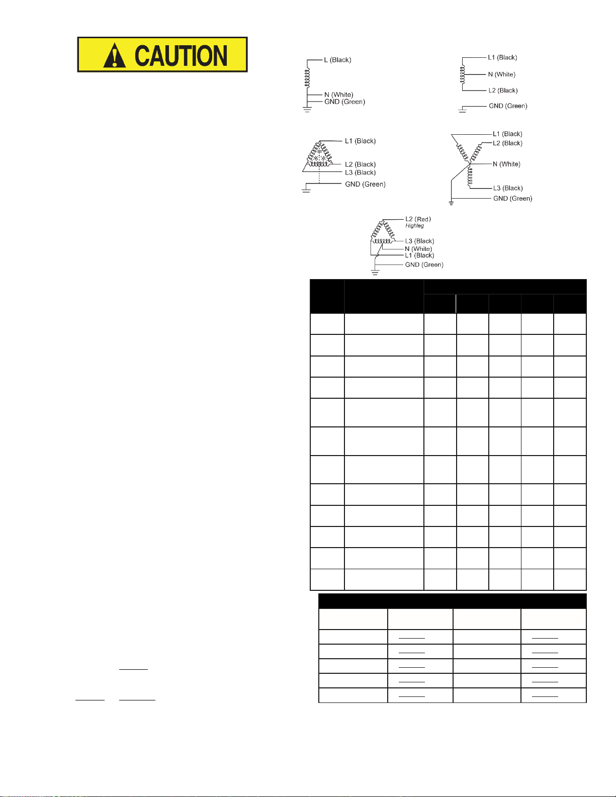
Make electrical connections appropriate for the application (see Power
System Diagrams). If your electrical system is not represented in the circuit
diagrams, contact manufacturer. Tighten the electrical terminals to the
terminal manufacturer’s specifications.
8. Energize panel or equipment and verify the LED status indicator is ON
(Blue).
9. Option Package – P/N suffix DG2 - Connecting Dry (voltage free) Relay
Contacts
• NOTE: SPD is equipped with sets of colored 18 to 22 AWG wires.
Blue = Common, Orange = N/C, Yellow = N/O when power is applied.
(SPDT; Form C)
• Contacts are rated at ≤60 W/125 VA (from 30 VDC @ 2 A to 150
VDC @ 0.4 A), max. switched current = 2 A.
• Follow rules for NEC class 2 wiring when routing alarm leads. To
maintain NEMA-4X (IP65) rating use appropriate cable and liquid
tight strain relief if needed (user supplied)
• Connect alarm circuit(s) to Normally Open (N/O) or Normally
Closed (N/C) circuits as required.
• If not using these contacts, please cap off the wires with a UL
Listed wire nut.
Power System Diagrams Showing SPD Wire Colors
Voltage
Code
Electrical System
Max. Continuous Operating Voltage (MCOV)
L-N
L-G
L-L
N-G
Hi Leg
1P1
100 to 127 Vac
Single Phase
150 V
150 V
-
150 V - 1P2
200 to 277 Vac
Single Phase
320 V
320 V
-
320 V - 1P4
415 to 480 Vac
Single Phase
550 V
550 V
-
550 V - 1S1
120/240 Vac, Split
Phase
150 V
150 V
300 V
150 V
-
3Y1
208 Y/120 V; 190
Y/110 V; 220 Y/127
V; 3 Φ Wye
150 V
150 V
300 V
150 V - 3Y2
480 Y/277 V; 440
Y/254 V; 460 Y/267
V, 3 Φ Wye
320 V
320 V
640 V
320 V
-
3Y22
3Y23
3Y24
380 Y/220 V; 400
Y/230 V; 415
Y/415 V, 3 Φ Wye
320 V
320 V
640 V
320 V
-
3Y3
600 Y/347 V; 525
Y/305 V; 3 Φ Wye
400 V
400 V
800 V
400 V - 3D1
120/240 Vac, 3 Φ,
High-Leg Delta
150 V
150 V
320 V
150 V
320 V
3N1X
120 Vac, 3 Φ Delta
or Wye
-
150 V
150 V - -
3N4
440 to 480 Vac, 3 Φ
Delta or Wye
-
550 V
550 V - -
3N6
525 to 600 Vac, 3 Φ
Delta or Wye
-
840 V
840 V - -
Installation Voltage Measurement Worksheet
Measure
between
Measurement
Value, fill-in
Measure
Between
Measurement
Value, fill-in
L1 - Gnd
VAC
L1 - Neut
VAC
L2 - Gnd
VAC
L2 - Neut
VAC
L3 - Gnd
VAC
L3 - Neut
VAC
Neut - Gnd
VAC
L1 - L3
VAC
L1 - L2
VAC
L2 - L3
VAC
BLUE LED = Good
The circuit is energized and protected.
RED LED = Replace SPD
The circuit is energized and unprotected.
Please replace the unit.
Note: The lid of the enclosure may be rotated 180 ⁰ for aesthetic reasons while de-energized
1P1
1P2
1P4
Single Phase
2 Wire + Ground
1S1
Single Phase
3 Wire + Ground
3N4
3N6
Three-Phase DELTA
3 Wire + Ground
No LED / LED is Out =
Investigate:
• The circuit could be de-energized
• The unit’s leads could be disconnected
• The unit could be damaged
3D1
Three-Phase
High-Leg Delta
4 Wire + Ground
3Y1
3Y2
3Y2x
3Y3
Three-Phase
4 Wire + Ground
Use Table 2 to verify system voltages prior to installation.
Table 1
Table 2
Intermatic, Incorporated
www.Intermatic.com
Warranty service is available by either (a) returning the product to the dealer from whom the unit was purchased or (b) completing a warranty claim online at www.intermatic.com. This warranty is
made by: Intermatic Incorporated, 1950 Innovation Way, Suite 300, Libertyville, IL 60048. For additional product or warranty information go to: http://www.Intermatic.com or call 815 -675-7000.
 Loading...