

Page 1

http://waterheatertimer.org/Intermatic-Air-controls-and-manuals.html
OWNER
INSTALLER
RC2000 SERIES
AIR ACTUATED SPA CONTROLS
INSTRUCTION
MANUAL
EFFECTIVE APRIL 1992
ONE CIRCUIT AIR SWITCH
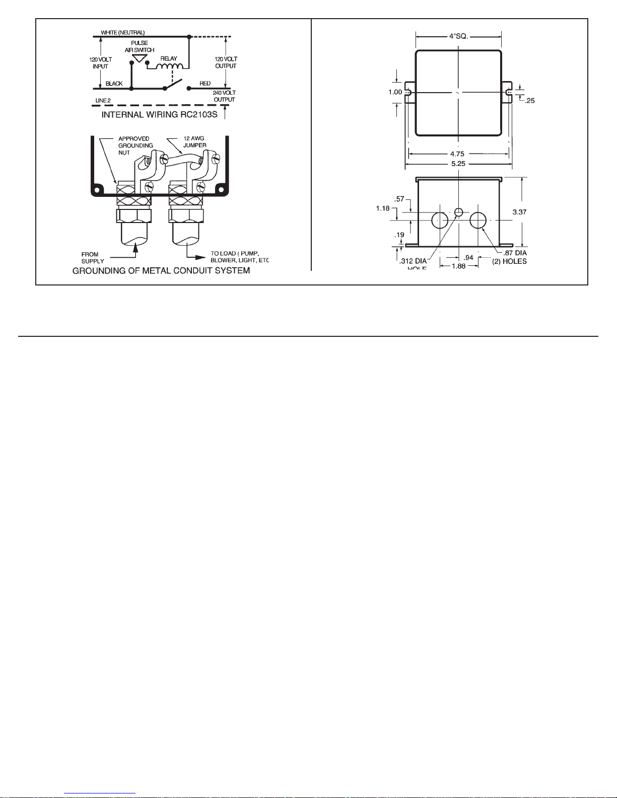
Model: RC2103S - Plastic Outdoor Enclosure
CIRCUIT: Single Pole Single Throw (ON/OFF)
RATINGS: 20 AMP. (R), 1500 Watt Tungsten, 1 HP. - 120 Volt 50/60 HZ.;
20 AMP. (R), 2 HP. - 240 Volt 50/60 HZ.
IMPORTANT SAFETY INSTRUCTIONS
READ AND FOLLOW ALL INSTRUCTIONS.
This Air Switch is designed for CONTROLLING the connected equipment only. ALL power must be disconnected at
the main panel before servicing this unit or the equipment it controls. THIS SWITCH IS NOT TO BE USED AS A
POWER DISCONNECT. Must be installed by licensed electrician in accordance with the NATIONAL ELECTRICAL
CODE and in accordance with all local codes and at least 5 ft. from edge or spa. Do not permit children to operate this
control or use the pool/spa unless they are closely supervised at all times.
SAVE THESE INSTRUCTIONS.
This Air Switch is designed to control one piece of equipment with one air button. It can control safely, without electricity at the
spa side, for example, a pump or light. Each time pressure is applied to the remote air button, the connected equipment will
alternately turn (ON/OFF).
TO INSTALL - Follow appropriate wiring diagram below. Use solid or stranded COPPER wire (only) to suit installation.
The equipment must have its own separate circuit with breaker suitable for power disconnect. Properly ground installation
as required by NEC and other codes. IMPORTANT: NEUTRAL WIRE MUST ALWAYS BE USED. Make Air Hose
connection. Use only non-conductive tubing to connect the air actuator. PLEASE NOTE: The maximum range of this
Air Switch is 100 ft. However, factors beyond the control of the manufacturer (such as the size of the air button, the I.D.
of the air hose etc.) will determine the actual distance between the mechanism and the air button.
Because of our commitment to continuing research and improvements, Intermatic Incorporated reserves the right to make
changes, without notice, in the specifications and material contained herein and shall not be responsible for any damages,
direct or consequential, caused by reliance on the material presented.
PISCATAWAY: 242 Old New Brunswick Road, Suite 100, Piscataway, NJ 08845/Los Angeles: 101 Rickenbacker Road, Los Angeles CA 90040
NORTHERN CA: 2350 S. Watney Way, Unit B, Fairfield, CA 94533/FORT LAUDERDALE: 3007 N. W. 60th Street Fort Lauderdale, FL 33309
158--00625
INTERMATIC INCORPORATED,
SPRING GROVE, IL 60081-9698
Page 2
TROUBLESHOOTING
SYMPTOM CAUSE(S) CORRECTIVE ACTION
1. Equipment will not operate. 1a. Air hose is disconnected. Check hose connections.
1b. Defective air button. Replace air button - see note 1.
1c. Water in the air hose. Blow-out air hose - see note 2.
1d. Defective air switch. Replace air switch - see note 3.
1e. Defective relay. Replace relay - see note 4.
1f. Air button is too far from control. Install larger air button.
2. Equipment will not turn off. 2a. Air hose is disconnected. Check hose connections.
2b. Defective air button. Replace air button - see note 1.
2c. Defective relay. Replace relay - see note 4.
3. Equipment turns on/off 3a. Defective air switch. Replace air switch - see note 3.
by itself. 3b. Water in the air hose. Blow-out air hose - see note 2.
3c. Changing air pressure Reroute air hose - see note 2.
in air hose.
NOTES:
1. An air button with a ruptured seal or bellows inside, will not produce sufficient air pressure to operate the pulse air switch and
could lead to total breakdown - see note 3.
2. Water in the air hose is caused by a faulty air button (see note 1 above) or condensation. In either case it must be drained
and the cause found and corrected. To reduce condensation, protect the air hose from exposure to direct sun, ice or frequent
temperature fluctuations.
3. A defective air switch is the likely result of water in the air delivery system (see note 2 above). A permanently closed air
switch (due to water) will energize the alternate action relay coil permanently thus causing the coil to overheat. It is therefore
good practice to check and replace, if necessary, other components (such as air button, air switch and relay) in order to
correct the fault.
4. A defective relay is either due to contact or coil failure. Contact failure is caused by overload or cross-wiring and coil failure
is caused by 240 volt connected across the 120 volt coil or permanently applied 120 volt. (The relay is designed for
intermittent duty only.) Permanently applied 120 volt could be the result of water in the air hose (see note 3 above) or a spa
cover placed over (and depressing) the air button. In any case, the cause must be found, corrected and the relay replaced.
158--00625 (side 2)
 Loading...