

Intermatic R8815P101C Supplementary Manual
Model R8815P101C
PROGRAM TIME SWITCH WITH
14-DAY "SKIPPER®" MECHANISM
WITH RAIN SENSOR CONNECTIONS.
FOR UP TO 60 OPERATIONS PER DAY
RELAY CONTACTS: DOUBLE POLE SINGLE THROW
30 AMP., 1 1/2 H.P. 120 VOLTS A.C.
CLOCK MOTOR: 125 VOLTS - 60 HZ.
PROGRAMMING INSTRUCTIONS:
1. TO SET FIRST ZONE: For watering, push gold pin into slot on yellow
dial at desired ON time. For each 12 minutes of additional watering
add one pin WITHOUT skipping a slot.
2. TO CHANGE ZONES: Leave one blank slot on yellow dial after ON
line (gold pin), and valve will automatically advance to next zone.
3. TO SET ADDITIONAL ZONES: Repeat steps 1 and 2. REMEMBER
to leave blank space between zones
4. TO SET TIME OF DAY: Turn yellow dial CLOCKWISE, until correct
line is at end of silver time pointer. Do NOT turn silver pointer.
5. TO SKIP DAYS: Turn black skipper wheel COUNTER-CLOCKWISE
until today's day is in front of "14" arrow. Press pins DOWN on days
of NO watering. The skipper wheel must have all pins UP for daily
watering.
6. PUT SELECTOR SWITCH IN AUTO: This switch can be used to turn
the system ON or OFF for manual operation without affecting the set
program.
7. PUT RAIN SENSOR OVERRIDE SWITCH IN “ON” POSITION: The
OVERRIDE position can be used to override the rain sensor for testing
purposes and must be used if the time switch is being used without a
rain sensor.
IMPORTANT NOTICE: Use the one silver pin that is located at Midnight
on the yellow dial, it advances the skipper wheel automatically. Do NOT
use multiple silver pins.
Follow The National Electrical Code and local code requirements when
installing this time switch.
CAUTION: Always disconnect power at main panel before servicing
this Switch or the equipment it controls.
INTERMATIC INCORPORATED
SPRING GROVE, ILLINOIS 60081-9698
158T8602 MADE AND PRINTED IN U.S.A.
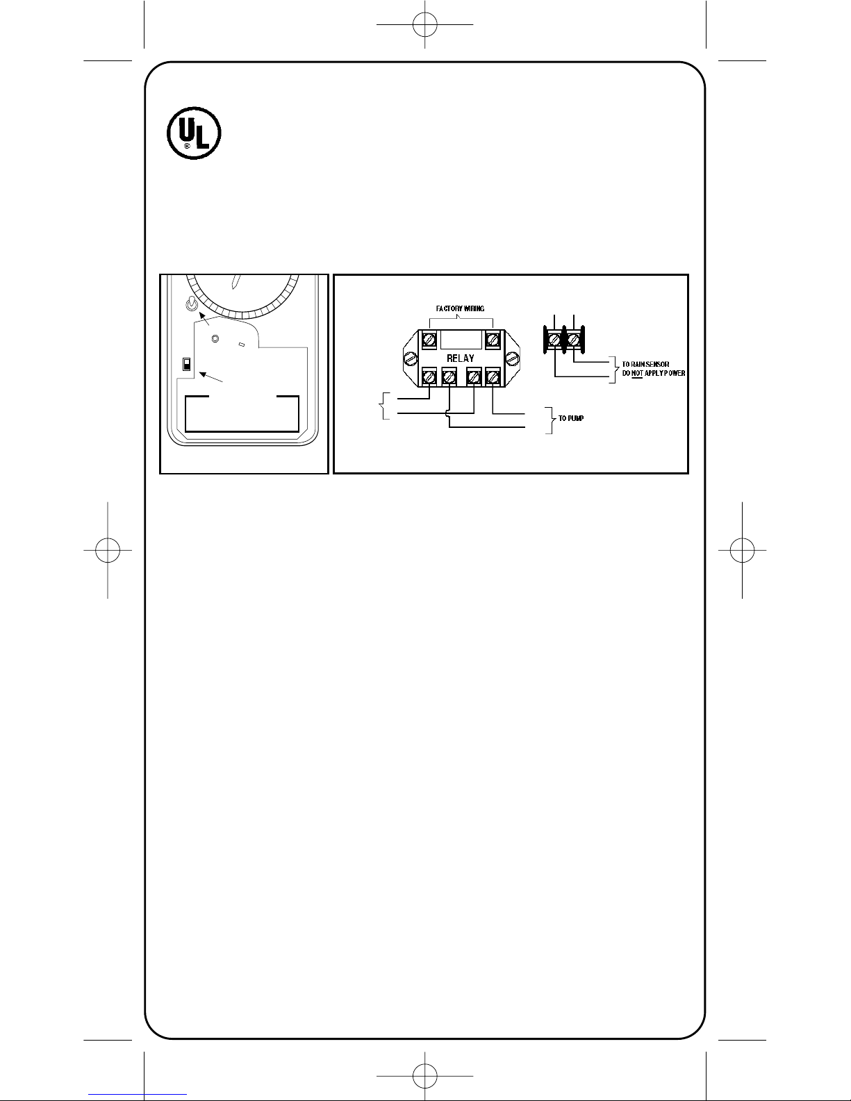
FACTORY WIRING
TO PUMP
240 VOLT
POWER
SUPPLY
RELAY
TO RAIN
SENSOR DO NOT
APPLY POWER
WIRING DIAGRAM
ON
OVERRIDE
Selector Switch
Rain Sensor
Override Switch
TURN POWER OFF AT MAIN PANEL BEFORE SERVICING THIS
SWITCH OR THE EQUIPMENT IT CONTROLS. CONNECT THE
COPPER CONDUCTORS TO SWITCH TERMINALS. THIS
TERMINAL MUST BE REPLACED AFTER WIRING TO PREVENT
SHOCK. KEEP CASE LOCKED AT ALL TIMES.
CAUTION — RISK OF ELECTRIC SHOCK
FIGURE 1
LISTED
885L
WIRING DIAGRAM
FIGURE 1
FACTORY WIRING
(24 VAC)
120 VOLT
POWER
SUPPLY
LINE
NEUTRAL
NEUTRAL
LINE
158T8602.QXD 3/4/04 10:39 AM Page 1
 Loading...