

Page 1
PE25K120V
25,000 gallons
PE25K240V
PE40K120V
40,000 gallons
PE40K240V
The Natural Way To Purify Your Pool or Spa
IMPORTANT SAFETY INSTRUCTIONS
This manual must be given to the homeowner to ensure warranty coverage.
When installing and operating this Product and other associated equipment, basic safety precautions should
always be followed, including the following:
1. DO NOT OPEN THE GENERATOR BOX – NOT A SERVICABLE UNIT
2. READ AND FOLLOW ALL INSTRUCTIONS
3. Disconnect all AC power before installation.
4. WARNING – To reduce the risk of injury, do not permit children to use this product.
5. This Control must be installed by a qualified electrician, according to National and Local Electrical Codes.
6. The Control Box must be mounted vertically on a flat surface and a minimum of 5 ft (1.5m) horizontal
distance (or more, if local codes require) from the pool/spa
READ, FOLLOW AND SAVE THIS INSTRUCTION MANUAL
Intermatic Incorporated, 7777 Winn Road, Spring Grove, IL 60081
Questions concerning your Salt Chlorine Generator? Call 321-274-0059 or 815-675-7000
Page 2

Table Of Contents
Section 1. General Information...........................................................................1
Section 2. Important Safety Information ............................................................1
Section 3. Installation Instructions......................................................................2
3.1 General Information.................................................................2
3.2 Plumbing Your System ............................................................3
3.3 Installing the Cell.....................................................................4
3.4 Installing the Flow Sensor........................................................5
3.5 Mounting the Control Box .......................................................5
3.6 Wiring the Control Box............................................................7
3.7 Wiring the Flow Sensor............................................................8
Section 4. Startup Instructions............................................................................8
4.1 Before Adding Salt...................................................................8
4.2 Adding Salt...............................................................................9
4.3 Acceptable & Unacceptable Salts ............................................9
4.4 Salinity Demand Table.............................................................10
4.5 Calculating the Size of the Pool...............................................10
Section 5. Operating Instructions........................................................................11
5.1 Chlorinator Specifics................................................................11
5.2 Filtration...................................................................................11
5.3 Sanitation/Oxidation.................................................................11
5.4 Basic Operation........................................................................11
5.5 Winterizing...............................................................................12
5.6 Spring Startup...........................................................................12
5.7 Controls....................................................................................13
-Red Light ...............................................................................13
-Power Meter...........................................................................13
-On/Off Light ..........................................................................13
-Flow Light..............................................................................13
-Salinity Indicator....................................................................14
-Power Switch .........................................................................14
Section 6. Maintenance / Cleaning .....................................................................15
6.1 Cell Maintenance......................................................................15
6.2 Cell Cleaning............................................................................15
-Cleaning with optional cleaning cap......................................15
-Cleaning without optional cleaning cap.................................16
6.3 Understanding the chemistry....................................................17
6.4 Calculating Saturation Index....................................................19
Section 7. Troubleshooting.................................................................................20
Section 8. Warranty & Registration....................................................................24
Page 3
Page 1
Section 1. General Information
Congratulations on the purchase of your new Salt Chlorine Generator. Your
purchase will minimize the efforts needed to maintain your pool and maximize your
enjoyment for many years. Before installation or operation, please read these
instructions carefully. This manual contains easy to follow step-by-step procedures
to properly install and operate your system. A little time spent understanding your
system and its parts will assure successful, trouble-free installation and usage.
When working around your pool, please take care to avoid hazards such as
electrical wires and chemicals. CAUTION! Safety comes first!
Section 2. Important Safety Instructions
READ AND FOLLOW ALL INSTRUCTIONS
All electrical work must be performed by a licensed electrician and conform to all nat ional, state,
and local codes. When installing and using this electrical equipment, basic safety precautions should
always be followed, including the following:
WARNING
DO NOT OPEN THE GENERATOR BOX – NOT A SERVICABLE UNIT
DANGER
DISCONNECT ALL AC POWER BEFORE INSTALLATION
WARNING
To reduce the risk of injury, do not permit children to use thisproduct.
WARNING
The Control Box must be mounted vertically on a flat surface and a minimum of 5 ft (1.5m)
horizontal distance (or more, if local codes require) from the pool/spa.
WARNING
The power cable must be hardwired to the time clock so that the system cannot operate without
the pump.
Page 4
CAUTION
In Canada and some other regions, local codes require the unit be connected only to a circuit
that is protected by a ground-fault circuit-interrupter (GFCI). The installer should provide this
GFCI requirement. The GFCI should be tested on a regular basis by pushing the test button. If
the GFCI fails to operate correctly, there is ground current flowing indicating the po ssibility of
an electric shock. Do not use this unit. Disconnect unit and have a qualified professional corr ect
the problem before using.
WARNING
A Build-up of flammable fumes can result in a hazardous condition if the Cell is allowed to
operate without flow. This machine must be operated only with an approved in-line flow sensor.
CAUTION
The flow Sensor must be installed between the last piece of apparatus and the Cell, upstream of
the Cell.
DANGER
Page 2
ALWAYS ADD ACID TO WATER, NEVER WATER TO ACID
SAVE THESE INSTRUCTIONS
Section 3. Installation Instructions
Section 3.1 General Information: The system comes in three sections, the Control
Box, cell and Flow Sensor. They are manufactured from the latest corrosion resistant
materials to give you years of trouble free use, and installing them in the most sheltered
position from sun and water will protect them from extreme weather conditions for years
to come.
Safety Measures
1. Only operate the system with an approved flow sensor.
2. See safety measures and warnings on page 2 of this manual.
Additional Materials Required
1. PVC solvent cement and priming fluid
2. Hacksaw or pipe cutters
3. Screwdrivers
4. Drill
5. Teflon Tape (a.k.a. Plumber’s Tape)
6. Silicone Sealant (DO NOT USE silicone glue or petroleum jelly).
7. Pipe adaptors (i.e. reducer couplings) if needed for systems with 1 ½ inch plumbing.
Page 5

Page 3
Section 3.2 Plumbing Your System
MODEL CONFIRMATION: Confirm you have the
correct model for your pool size by checking the model
number on the cell:
• PE25K < 25,000 gallons (100,000 liters)
• PE40K < 40,000 gallons (150,000 liters)
Page 6
Page 4
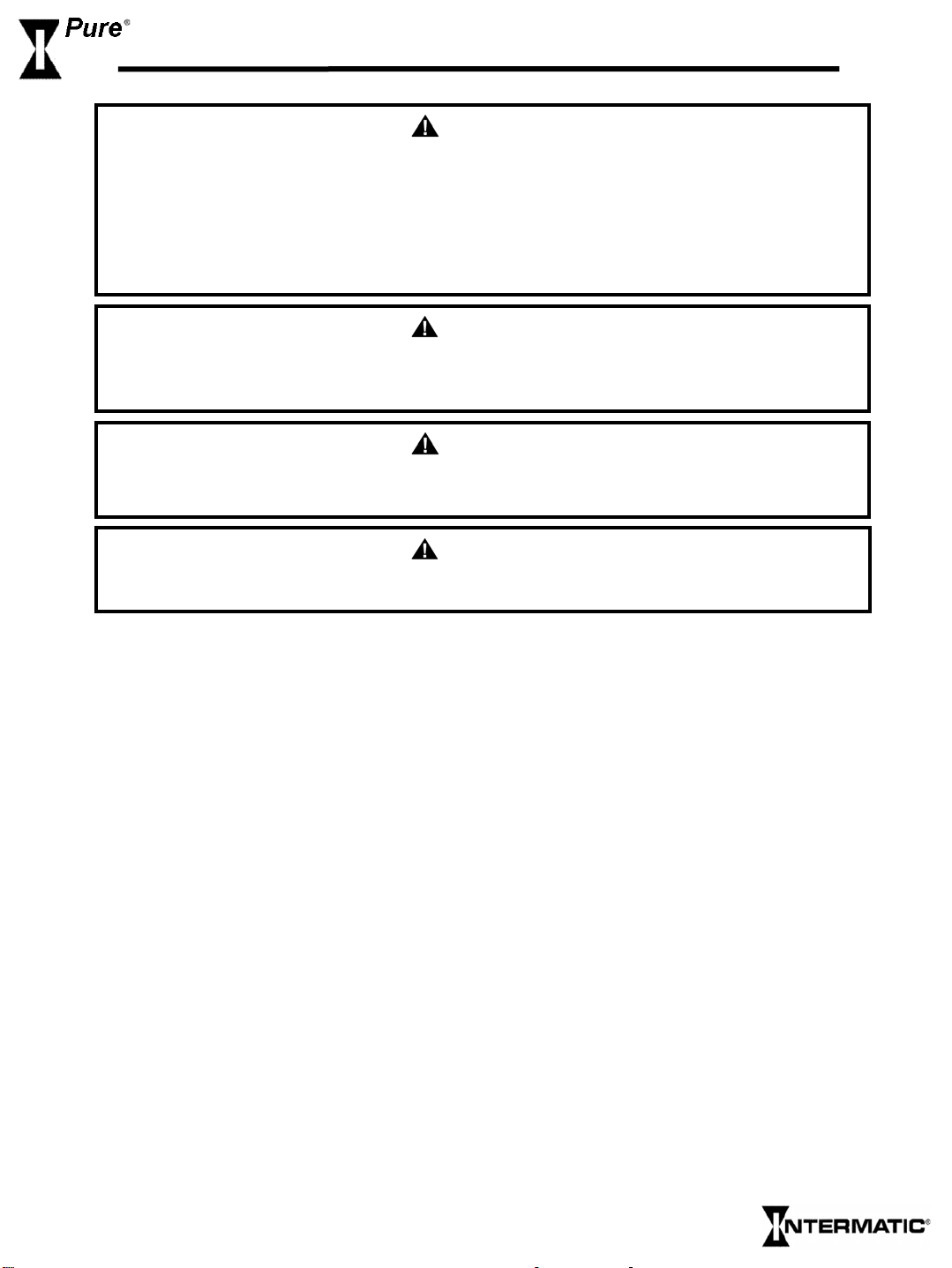
Section 3.3 Installing the Cell
NOTE
Lay out equipment pieces to be sure there is enough pipe space between the last piece of apparatus and
the tees in the return line to fit the Flow Sensor and the Cell. A Vertical Installation may be used to save
space.
1. The Cell and Flow Sensor must be installed
downstream from the filter and heating
devices but before any tees in the return
line. The Cell may be installed horizontally
or vertically so long as the Cell is pointed in
the direction of flow and is installed
immediately after the enclosed Flow Sensor
(see diagram above).
2. Approximately 15 inches (~380 mm) of available pipe length will be needed for horizontal
installations of the Flow Sensor and Cell. Vertical installations can be made to take less space.
3. On the pipe where the cell will be installed, mark two lines 11 3/4 inches (300mm) apart and cut out
using hacksaw or pipe cut
4. Unscrew and remove the barr el unions (i.e. barrel nuts and slip connections) from either end of the
Cell. Thread one of the barrel nuts over the pipe and glue its slip connection to the cut pipe.
5. Hold up the Cell wit h t he seco nd union to g auge the proper distance befo r e threading the second nut
and gluing the second slip.
ters.
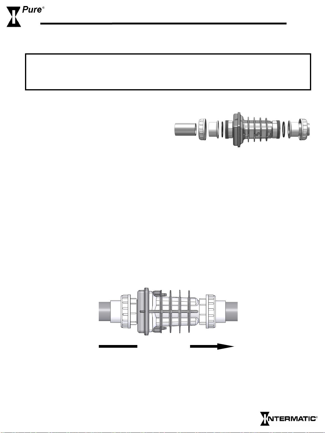
Flow direction
6. After the glue had sufficient drying time, place the Cell with the o-rings into the opening between
the two ends of the pipe and tighten the unions making sure that the Cell is installed with the arrow
pointing in the same direction as the flow (i.e. water should enter from the side with the blue cap).
Page 7
Page 5
Section 3.4 Installing the Flow Sensor
Flow direction
1. Install the Flow Sensor between the last piece of apparatus and the Cell (if installed after the Cell,
damage to the sensor may result). When possible, install on a horizontal pipe.
2. Mark two lines on the pipe 3 inches (~76 mm) apart and cut with a hacksaw or pipe cutters.
3. Clean and glue the “T” connector (included) to the pipe making sure that the threaded end with the
sensor is on the topside of the pipe.
4. Be sure the arrow on the top of the Flow Sensor is pointing in the direct ion of f low, and that no glue
touches the paddle inside the sensor as it may cause it to jam.
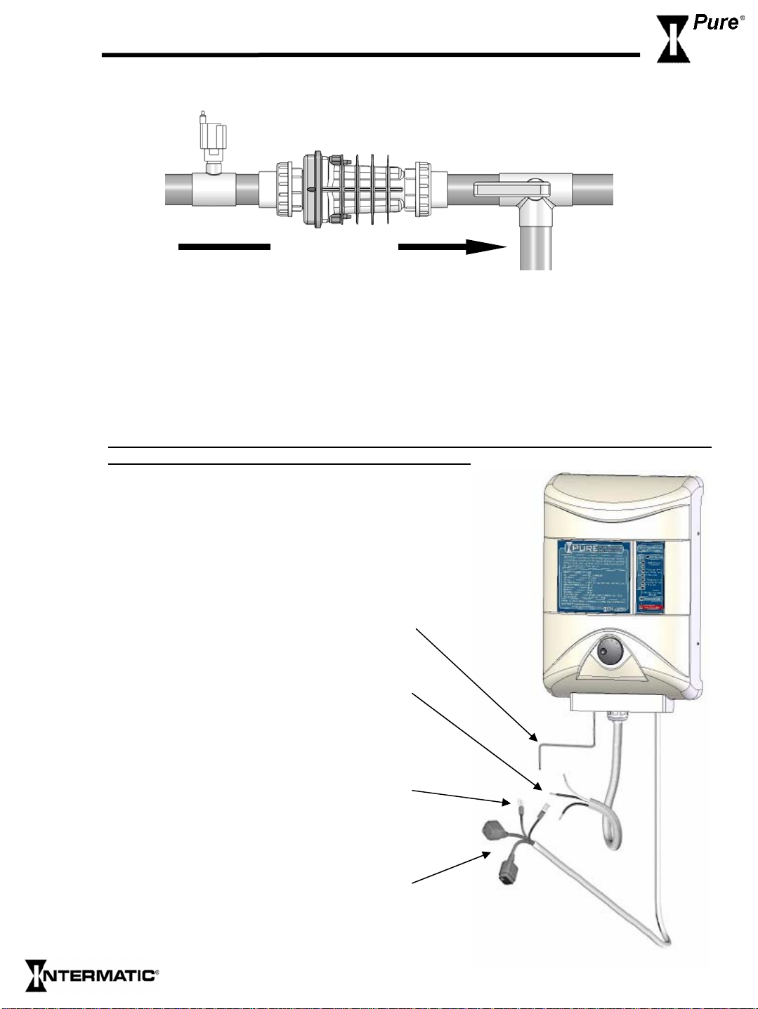
Section 3.5 Mounting the Control Box
1. It’s important to identify and understand the
purpose of each cord at the bottom of your
Control Box. Please refer to the picture for cord
identification and application prior to mounting:
BONDING – Bonding is recommended and may
be required by local code. The bonding lug is
found on the bottom of the Control Box.
POWER CORD – Hardwire the power cable to
the time clock as indicated in the section titled
“Wiring the Control Box”. Check label on side of
Control Box for the proper voltage specification
of your system (i.e. 120v or 240v)
FLOW SENSOR – The flow switch MUST BE
connected to the Control Box in order for the
system to work properly. Ensure proper flow
switch operation once installed.
CELL CONNECTORS – Connect the two black
wires from the Control Box to the two metal studs
on the sides of the Cell and tighten firmly with a
screwdriver by hand. See “Wiring the Control
Box” for further instructions.
Page 8

Page 6
Section 3.5 Mounting the Control Box (Continued)
2. The Control Box must be mounted vertically on a flat surface and a minimum of 5 ft (1.5m)
horizontal distance (or more, if local codes require) from the pool/spa.
3. Locate a po sition for your Control Box within 10 ft (~3 meters) of where the Cell will be installed
and within 2 ft of the power supply to ensure enough wire is available.
4. Because the box acts as a heat sink dispersing heat from
inside the box, do not block the four sides of the Control
Box. Do Not mount the system inside a panel or tight
enclosed area.
5. Secure the hanging rack on the wall using the enclosed
screws and anchors. 1/4” (8mm) drill bit should be used for
the anchor holes.
WARNING
All four sides of Control Box
must have air ventilation for
proper heat dissipation.
6. Hang the C ontrol Box on the mounted hanging rack.
7. Hardwire the power cable to the time clock as
8. Do not extend the cable leading to the cell. This
indicated in the wiring instructions below.
*Check the label on the side of the Control Box
for the proper voltage specification on your
system (i.e. 120v or 240v).
decreases the system’s efficiency and will void
warranty coverage. Please contact the
manufacturer for installations demanding a
longer cell cable.
Page 9

Page 7
Section 3.6 Wiring the Control Box
Check whether your chlorine generator operates on 120 volts or 240 volts (see label on the left
side of the Control Box), and be sure to wire the system accordingly. It is critical to wire the
chlorine generator in such a way that it can only operate when the pump is operating (i.e. load
side). See instructions below for details.
1. At tach the green ground wire to the grounding lug or bar.
2. Connect the black Load wire from the chlorine generator to
Load 1 of the time clock.
3. If wiring a 240 Volt generator, connect the third wire to Load 2
of the time clock. If wiring a 120 Volt generator, connect the
third wire to the Neutral lug or bar on the timer (see label on the
left side of the Control Box to confirm voltage).
4. Bonding is recommended and may be required by local code.
The bonding lug is found on the bottom of the Con trol Box.
CAUTION
5. Connect the two black wires from the Control Box to the two metal
studs on the sides of the Cell. These wires are interchangeable.
6. Tighten firmly by hand, with a screwdriver. To avoid damage to the
screws, DO NOT use a power screwdriver.
7. Push the plastic terminal covers up to cover the terminal connection
until they click into place. This will ensure a watertight connection.
Page 10

Section 3.7 Wiring the Flow Sensor
1. Find the two 18 AWG wires with the ¼” Quick connect
terminals from the Cell cable and push them on their
respective connectors on the Flow Sensor. These wires
are interchangeable.
NOTE
Flow Sensor wires are interchangeable. You
must have flow sensor connected in order for
the Salt Chlorine Generator system to
work properly.
Flow Sensor
Page 8
Section 4. Startup Instructions
Section 4.1 Before Adding Salt
Balance the chemicals
See the section titled “Understanding the Chemistry” for recommended water balance. Also, add 1
quart of metal remover and 1 quart of non-copper based algaecide to the pool, according to the
manufacturers instructions. This will ensure that the transition to the Natural Generator system will be
quick and trouble-free.
Measure existing salt in your pool.
Years of liquid chlorine use may cause the salt reading to be higher due to residual salt.
New Pools
Wait 10-14 days, or longer if specified by the pool builder, for plaster to cure befor e adding salt or
operating the I-Pure Salt Chlorine Generator.
Biguanide Pools
If installing on a pool using Biguanide sanitizers, all Biguanides must be removed before system startup.
Page 11

Page 9
Section 4.2 Adding Salt
1. Determine how much salt is needed from the Salinity Demand Table on the following page.
This table is based on a salt concentration of 3500 ppm (approximately 1/3 of 1%). More may
be added for larger pools (e.g. 4000 p
2. Keep the pump on to circulate the water.
3. Dist ribute the dete rmined amount of salt even ly around the pool. To avoid clogging the filter
or damaging the Control Box and pump, do not add salt through the skimmer or surge tank.
Brushing the bottom helps dissolve the salt.
4. The readout on the chlorine generator may fluctuate until the salt is fully dissolved.
pm) and less for very small bodies of water.
Section 4.3 Acceptable & Unacceptable Salts
GOOD
The best salt is an evaporated,
granulated, food quality salt.
Water softener salt pellets may be
used but will take longer to dissolve.
“99.9%” pure salt.
“Solar” salt.
BAD
Iodized salt.
Salts with anti-caking agents (i.e.
yellow prussiate of soda or sodium
ferrocyanide) because they have iron
and will yellow the fittings.
Rock salt because of the dirt mixed
with the rock salt.
Calcium chloride; it is not a salt.
Use only sodium chloride.
Page 12

Section 4.4 Salinity Demand Table (in lbs.)
Locate the current salt concentration at the top of the chart (e.g. 1000ppm). Then locate the size of your
pool on the left (e.g. 12,000 gallons). Run these figures down and across until they meet. That number is
the number of pounds of salt required for your pool.
Salt level before addition in PPM
Water volume in thousands of Galloons
4
6
8
10
12
14
16
18
20
22
24
26
28
30
32
34
36
38
40
42
44
46
48
50
0 500 1000 1500 2000 2500 3000 3500 4500
How much salt to add – in pounds
How much sat to add – in pounds
117 100 83 67 50 33 17 0 OK
175 150 125 100 75 50 25 0 OK
234 200 167 133 100 67 33 0 OK
292 250 209 167 125 83 42 0 OK
350 300 250 200 150 100 50 0 OK
409 350 292 234 175 117 58 0 OK
467 400 334 267 200 133 67 0 OK
525 450 375 300 225 150 75 0 OK
584 500 417 334 250 167 83 0 OK
642 550 459 367 275 183 92 0 OK
701 600 500 400 300 200 100 0 OK
759 651 542 434 325 217 108 0 OK
817 701 584 467 350 234 117 0 OK
876 751 626 500 375 250 125 0 OK
934 801 667 534 400 267 133 0 OK
992 851 709 567 425 284 142 0 OK
1051 901 751 600 450 300 150 0 OK
1109 951 792 634 475 317 158 0 OK
1168 1001 834 667 500 334 167 0 OK
1226 1051 876 701 525 350 175 0 OK
1284 1101 917 734 550 367 183 0 OK
1343 1151 959 767 575 384 192 0 OK
1401 1201 1001 801 600 400 200 0 OK
1460 1251 1043 834 626 417 209 0 OK
Page 10
Section 4.5 Calculating the Size of the Pool
Gallons (dimensions are in feet)
Rectangular
Round
Oval
Length x Width x Average Depth x 7.5
Diameter x Diameter x Average Depth x 5.9
Length x Width x Average Depth x 6.7
Liters (dimensions are in meters)
Length x Width x Average Depth x 1000
Diameter x Diameter x Average Depth x 785
Length x Width x Average Depth x 893
Page 13

Page 11
Section 5. Operating Instructions
Section 5.1 Chlorinator Specifics
This product is an automatic Natural Chlorine Generator for pool and/or spa sanitation. It is the
workhorse of chlorine generators. The system uses a very low concentration of salt, less than the
concentration in a human teardrop, and converts it into free chlorine that kills a lgae and bacteria in
your pool. After killing the algae and bacteria, the chlorine reverts back into sodium chloride. This
process of purification continues, making the need to add extra sanitizing chemicals to your pool
virtually unnecessary.
The level of necessary chlorine in the pool is affected by a number of factors such as sunlight, bather
load, debris and water temperature, all of which increase sanitation and filtration demand.
Section 5.2 Filtration
Proper filtration is critical for maintaining clean healthy water. Filtration increases clarity, and the
Natural Chlorine Generator increases sanitation and oxidation. It is customarily required in the pool
industry that all the water in the pool pass through the filter at l east one and a half (1 ½) times per day
(~ 8 hours on most pools). During very heavy usage, the filter and chlorine generator may be run
continuously.
Inadequate filtration: Inadequate filtration reduces water clarity and makes more work for the
generator.
Section 5.3 Sanitation/Oxidation
The Natural Chlorine Generator has little effect on pH, total alkalinity, or stabilizer levels. These must
still be monitored and adjusted to allow the system to have its greatest effect. If you use a good quality
pool test kit and follow the simple instructions outlined in this manual, your Natural Chlorine Generator
will help you maintain a sparkling clean, trouble-free pool for many years with minimal effort. See the
section titled “Understanding the Chemistry” for more information.
Section 5.4 Basic Operation
The Natural Chlorine Generator produces a pure form of chlorine to sanitize and oxidize your pool
water. The chlorine residual needs to be maintained at 1-3 ppm. This may be tested using a standard kit
or by your local pool store. To obtain the optimal res idual build up of chlorine, the best time to run your
filter is in the early morning and after 4:00 pm when there is less UV to destroy the chlorine produced,
leaving chlorine in the pool to oxidize the unwanted foreign matter.
Page 14

To generate more chlorine
1. Turn the Control Knob to a higher setting as necessary, 10% to 100%
chlorine production level. (See “Power Meter” in the next section)
2. Ensure sufficient run time (at least 8 hours / 1 ½ turnovers).
3. Ensure salt level is correct and the Cell is clean (see “Salinity Indicator” in
the next section).
4. Ensure proper water balance including pH and stabilizer levels (see
“Understanding the Chemistry” for recommended levels).
5. Point pool jets down and to the side.
* Summer weather increases demands for chlorine.
To decrease chlorine production:
1. Turn the Control Knob to a lower setting, 10% to 100% chlorine
production level. (See “Power Meter” in the next section)
2. Decrease run time as necessary.
Section 5.5 Winterizing
Page 12
* Rotate knob clockwise
to increase chlorine
production
•Rotate knob counter
clockwise to decrease
chlorine production
Just like the pool plumbing, freezing may damage the system’s Cell and Flow Sensor. If severe or
extended periods of freezing temperatures are possible, drain all water from the pump, filte r, and supply
and return lines before any freezing conditions occur.
Section 5.6 Spring Start-Up
DO NOT turn on the system until the pool water chemistry has been brought to required levels. See
“Startup” section for more information.
Page 15

Page 13
Section 5.7 Controls
Red Light - Above the Power Meter indicates that the salt level in the pool is on the high side.
This does not harm the Natural Generator, but is provided as a cautionary notice to the user not to
add more salt to the pool. Operation at very high levels (i.e. above 5500ppm) is not recommended.
Slowly turn down the Control Knob until the desired Power Meter light illuminates (i.e. desired
chlorine production level).
Power Meter – These lights indicate the system’s chlorine
output (i.e. 10% to 100% production rate). The higher
lights indicate higher chlorine production. Turning the
control knob clockwise increases chlorine production and
should increase the chlorine output reading (i.e. 10% to
100% production rate).
If Power Meter lights go up & down quickly: The salt lev el
is high. Slowly turn the Control Knob down
(counterclockwise) until the desired Power Meter light
illuminates. If the lights continue to go up and down after
the Control Knob was turned down, the salt level is
exceedingly high, and should be reduced immediately by
draining a significant amount of pool water and refilling the
(Please check with your local pool professional prior to
pool.
draining the pool)
On/Off Light - When the system is turned on and the
pump is operating, the green On/Off Light should be
illuminated indicating that power is reaching the Control
Box.
Flow Light - Red light should NOT be illuminated during proper operation; a constant red light
signifies insufficient flow. When first turning on the circulation pump, the red light may turn on and
of
f until the air is pushed out of th e pump lines and sufficient water flow is achieved. This is normal
and ensures that the generator automatically shuts off if the pump fails to prime or a blockage occurs.
See trouble-shooting section if red light remains on.
Page 16

Salinity Indicator -- To check the salt level, turn the Control Knob clockwise to full power and
check the light reading.
100% reading indicates that the salt level is sufficient. Return
the Control Knob to the desired chlorine production setting
depending on the chlorine level in your pool (10% to 100%
production rate).
Red Light - above the Power Meter indicates that the salt level
in the pool is on the high side. This does not harm the Natural
Generator, but is provided as a cautionary notice to the user not to
add more salt to the pool. Operation at very high levels (i.e. above
5500ppm) is not recommended. Slowly turn down the Control
Knob until the desired Power Meter light illuminates (i.e. desired
chlorine production level).
Power Meter lights go up & down quickly: The salt
If
level is high. Slowly turn down the Control Knob
(counterclockwise) until the desired Power Meter light illuminates.
If the lights continue to go up and down after the Control Knob
was turned down, the salt level is exceedingly h igh, and should be
reduced immediately by draining a significant amount of pool
water and refilling the pool.
professional prior to draining the pool)
(Please check with your local pool
Page 14
Readings between 10% and 80% indicate a low salt level,
except when the Cell is worn or calcified. Check the Cell to ensure
the blades are in good condition and not coated with calcium
buildup. Cleaning the Cell is recommended if it is calcified or if
the readout seems ques tionable. Before a dding salt, it is advisable
to have the salt level professionally checked.
Page 17

Page 15
Section 6. Maintenance/Cleaning
Maintaining your I-Pure System requires minimal
work but will maximize the performance and life of the
system.
Pool water should be tested bi-monthly.
Section 6.1 Cell Maintenance
Our clear Cell allows for easy regular inspections for calcium build up. Visually check the Cell
periodically, and clean it as necessary (1 to 2 times per year). Advanced self-cleaning technologies,
including reverse polarization and IBT™ help the cell stay cleaner than other self-cleaning cells, but
minimal biannual cleanings are required.
Section 6.2 Cell Cleaning
NOTE
Do Not use metal or other hard objects to clean the cell as this could scratch the precious coating on the
plates and void the warranty.
NOTE:
DANGER
Always add acid to water, NOT water to acid
Diluted Muriatic Acid solution = 10 parts water to 1 part acid
Note: Follow the instructions of the acid manufacturer.
Cleaning With Optional Cleaning Cap
1. Remove the cell from the line by undoing the
electrical connections from the Cell and the
barrel unions from the cell ends.
2. Remove the black o-rings on the ends of the
Cell. (Fig. 1)
3. Attach the Cell Cleaning Cap to one end of
Cell. (Fig. 2)
Fig. 2
Fig. 1
Page 18

Cleaning With Optional Cleaning Cap (continued)
4. Pour into cell, either undiluted white distilled
vinegar, or a solution of diluted muriati c aci d (5
parts water to 1 part muriatic acid). (Fig. 3)
5. Wait for foaming to stop (5-10 minutes).
6. If muriatic acid was used, safely dispose of it by
pouring it into your pool.
7. Rinse cell with water hose.
8. Put the O-ring back in place and re-install the
Cell in the line.
9. Reconnect the electrical wir es, being sure to
tighten the screws on the electrical wires firmly.
Fig. 3
Cleaning Without Optional Cleaning Cap
1. Remo ve the cell from the line by undoing the ele ctrical connections from the Cell and the
barrel unions from the cell ends.
2. Remove the black o-rings on the ends of the Cell.
3. Soak entire cell either in undiluted white
distilled vinegar or in a solution of diluted
muriatic acid (5 parts water to 1 part muriatic
acid). (Fig. 4)
4. Wait for foaming to stop (5-10 minutes when
using muriatic acid; vinegar takes longer).
5. If muriatic acid was used, safely dispose of it by
pouring it into your pool.
6. Rinse cell with water hose.
7. Put the O-ring back in place and re-install the
Cell in the line.
8. Reconnect the electrical wir es, being sure to
tighten the screws on the electrical wires firmly.
Fig. 4
Page 16
Optional
1. Lubricating the o-rings with a rubber lubricant (e.g. silicone) helps improve the seal of the
fittings, but be sure not to use silicone glue, petroleum jelly (such as Vaseline), or other agents
that could deteriorate the o-rings.
2. Smear the two electrical connections on the outside of the cell with electrical lubricant.
Page 19

Page 17
Section 6.3 Understanding The Chemistry
Below is a table showing the recommended balance levels followed by a more detailed explanation of the
factors affecting water chemistry. Maintaining these levels will prevent corrosion and scaling and will
ensure maximum enjoyment of the pool. You should test your water periodically. If the water
chemistry needs adjustment, your authorized dealer or most pool stores can supply you with the
appropriate chemicals and procedures. We recomm end you either take a copy of the Water Balance
Table to the pool store or notify the pool store that you are using a salt chlorine generator.
FACTORS IDEAL LEVELS
Salt…………………………. 3000 to 4000 ppm
Free Chlorine……………… 1 to 3 ppm
PH………………………….. 7.2 to 7.6
Total Alkalinity…………… 100 to 180 ppm (Depending on Saturation Index)
Stabilizer (Cyanuric Acid).. 40 to 80 ppm
Nitrates……………………. 0 ppm
Phosphates…………………. 0 ppm
Metals……………………….. 0 ppm
Calcium Hardness……..……100-300 (Depending on pool surface manufacturer recommendations)
Saturation Index…………... -0.3 to 0.3 (0 is ideal)
Salt is the power source of the Natural Chlorine Generator. To ensure maximum benefits with the use
of the system, the ideal salt level is 4000 ppm (parts per million). A low concentration of salt can hinder
the generator’s effectiveness. A concentration of salt above 55 00 ppm may cause corrosion damage to
the pool fixtures. See the Adding Salt section for more information.
Total Dissolved Solids (TDS) are different from the salt level of the pool, although TDS levels rise
by adding salt to pool water. This does not harm the poo l water chemistry or cla rity, but the pool water
professional that is testing for TDS must be aware that salt has been added for the chlorine generator
system. The pool professional doing the TDS test will get the accurate TDS level by subtracting the
salinity level.
Free Chlorine v. Combined Chlorine: The unpleasant smells and side effects often associated with
chlorine are actually caused by combined chlorine (i.e. chloramines). Combined chlorine is a chlorine
molecule that attacked a noxious particle in the water but has been unable to destroy that noxious
particle. This chlorine particle remains attached to the noxious particle until one of the two is burned
off; hence the term “combined chlorine” (a.k.a. chloramines). To burn off the noxious particle and free
up the chlorine again, pool owners have had to shock the pool periodically, but with the Natural
Chlorine Generator, the noxious particles are burned off within the generator’s Cell and the combined
chlorine is continuously converted back to free chlorine. The free chlorine level in the pool should be
maintained at 1 to 3 ppm. This level of free chlorine is comfort able to swim in with no unpleasant smells,
and it maintains prop er sanitizing power.
Page 20

Section 6.3 Understanding The Chemistry (continued)
PH is a measure of how acidic or basic a solution is. A scale of 0 to 14 is used to measure pH. Pure
water has a pH of 7 (neutral), acid solutions have a pH of less than 7, and basic (alkali) solutions have a
pH of more than 7. The recommended range is 7.2 to 7.6; chlorine is more effective within this range
and the water is most comfortable for bathers. Water with very high pH levels can cause scaling in the
pool, on the walls and in pipes. Low pH levels cause the water to be aggressive to the pool walls,
equipment, and bathers. To lower pH, add muriatic acid or dry acid, and to rais e pH, add soda ash
(sodium carbonate). Be sure to read and follow the respective manufacturer’s instructions.
Total Alkalinity mitigates changes in pH. It is often referred to as the “big brother of pH.” Keeping
proper levels of total alkalinity will help reduce unwanted fluctuations in pH levels. Total alkalinity is
also used to offset high or low levels of calcium hardness (see Saturation Index below). Add muriatic
acid or dry acid to lower total alkalinity and add baking soda (sodium bicarbonate) to raise total
alkalinity. Be sure to read and follow the respective manufacturer’s instructions.
Stabilizer (cyanuric acid) is necessary in most outdoor pools to maintain appropriate levels of
chlorine. Chlorine stabilizer helps give an appropriate residual chlorine reading of the pool water.
Without stabilizer, UV radiation from the sun destroys most chlorine within 2 hours, but excessive
amounts of stabilizer can decrease the effectiveness of chlorine. Chlorine stabilizer should be
maintained between 40-80 ppm to offset the harmful effect of the sun while maintaining the effectiveness
of the chlorine.
Page 18
Nitrates and Phosphates, generally associated with fertilizer thrown on nearby grass, can put very
high demands on chlorine; most often nitrates and phosphates will bring the chlorine level down to zero
(0). You can have your water tested for nitrates and phosphates by the local pool professional. No
nitrates or phosphates should be in your pool. To reduce phosphate levels, use a phosphate r emover
from your local pool professional. To reduce Nitrate levels, the pool must be partially or fully drained.
(Please check with your local pool professional prior to draining the pool)
Metals (certain metals) can cause loss of chlorine and can stain your pool. If a water test rev eals the
presence of metals, refer to your local pool professional for recommended methods of removal.
New Pool Water in recently filled or newly refinished pools may contain undesirable matter. The
ability of the Natural Chlorine Generator to purify your pool could be hindered by this matter so it is
best to balance the pool chemicals first.
Calcium Hardness, like pH and alkalinity, affects the water’s tendency to be aggressive or scale
forming. Lower levels of calcium hardness improve the chlorine generator’s performance and provide
softer silkier water for the swimmers.
Saturation Index determines whether the pool water is balanced, aggressive, or scale forming by
comprehensively taking into account all the relevant factors, including pH level, alkalinity level, calcium
hardness, and temperature. These factors should be tested periodically then plugged into the worksheet
on the following page to verify the proper balance of the pool and make adjustments as necessary.
Page 21

Page 19
Section 6.4 Calculating Saturation Index
Test the water for pH, Alkalinity, Calcium Hardness, and Temperature, then follow the simple steps
below:
1. Write your pools pH level here: pH ________
2. Find your Alkalinity level in the chart below, and write the corresponding Alkalinity Factor
here: Alkalinity Factor ________
Pool Alkalinity 5 25 50 75 100 150 200 300 400
Factor 0.7 1.4 1.7 1.9 2.0 2.2 2.3 2.5 2.6
3. Find your Calcium level in the chart below, and write t he corresponding Calcium Factor here:
Calcium Factor ________
Pool Calcium 5 25 50 75 100 150 200 300 400
Factor 0.3 1 1.3 1.5 1.6 1.8 1.9 2.1 2.2
4. Find your pool temperature in the chart below, and write the corresponding Temperature
Factor here: Temperature Factor ________
Pool Temp 32 37 46 53 60 66 76 84 94 105
Factor 0 0.1 0.2 0.3 0.4 0.5 0.6 0.7 0.8 0.9
5. Add the results from steps 1 through 4 above and write the result here: Total Above ________
____-12.2
6. Subtra ct 12.2 from step 5 and write the result here: Saturation Index = ________
NOTE
• If the Saturation Index above is between –0.3 and +0.3, the water is well balanced.
• If the Index is more than 0.3, the water will tend to cause scaling or get cloudy. Alkalinity and pH
should be reduced accordingly, but maintained within recommended levels.
• If the Index is less than -0.3, the water will tend to be aggressive toward the pool surface, equipment,
and bathers. Alkalinity and pH should be increased accordingly, but maintained within recommended
levels.
Page 22

Section 7. Troubleshooting
Evaluating the possible causes for each problem from top to bottom (first to last) will avoid any extra labor.
Check the salinity lev el.
¾
(See “Salinity Indicator” section).
Run pump at least 8 hours per day (1. 5
¾
tur novers of all the pool water ) .
Check wa t e r ch emistry; stabilizer should
¾
be bet ween 4 0- 80 pp m. If low, add stab ilizer
(See “ Und er standing the Chemistry”).
Check other chemistry and balance
¾
chemicals. (See “Und er sta nding the
Chemistry”).
See “Chlorine Level Low” abov e.
¾
Tur n Control Knob cloc k w ise to the
¾
desired setting.
Check main fuse on bottom of Control
¾
Box and replace if nec essary with a 6.3 Amp
250V AC 6x 32mm Slow Blow fuse.
One extr a fuse supplied with the sy stem.
Check the breaker leading t o the pool
¾
control.
Check for correct wiring.
¾
1. Chlorine Level Low
2. Green P oo l
3. On/Off Light is OFF: No
power
Low Salinity
¾
Pump operation time too
¾
short
Low Stabilizer (Cyanuric
¾
Acid)
Chemical Imbalance
¾
Chlorine level too low.
¾
System is turned off.
¾
Main fuse blew.
¾
Break er ju mped
¾
Power wires cut,
¾
disconnect ed, or incorre c tly
wired.
Page 20
4. On/Off Light is Solid
Green
5. Red Flow Light is Off
6. Flow Light is Turning On
and O f f
7. Flow Light is Solid Red
Other malfunct ion in
¾
Control Bo x.
System is on. This is
¾
normal.
This is normal.
¾
This is normal at initial
¾
start-up or if air bub bles are in
pipes.
Insu fficie n t wate r flo w
¾
from pump to Fl ow S ens or
and Cell.
Obs truc ti on or scale
¾
buildu p i n Cel l.
Flow Sensor was not
¾
ins t al l ed in the c orrec t
direction.
Flow Sensor is not fully
¾
threaded into the “T”
connector.
Contact w ar r anty hotline.
¾
Wait a few minutes for air to clear. If
¾
cont i nuous, see t roubleshooting section
“F low Light is Solid Red” below.
This is norm al for a few minutes at
¾
initial startup or if air is in the lines.
Clean fil t ers and straine rs .
¾
Check for cl osed valves, fault y pum p,
¾
etc.
Clean Cell a cc ord i ng to i nst ructio n
¾
manual . (S ee “Maintenan ce” sec ti on)
Turn Flow Sensor so arrow faces
¾
direct i on of wat er fl ow.
Fully thread the Flow Sensor into the
¾
T connec tor bei ng careful not t o da m age
the wires or s ensors .
Page 23

Page 21
Section 7. Troubleshooting (continued)
PROBLEM POSSIBLE CAUSES WHAT TO DO
This is norm al for a few minut es at
¾
Insu fficie n t wate r flo w
7. Flow Light is Solid Red
8. Power Meter lights do not
reach 100%
9. Salinity Low
¾
from pump t o F low S ensor
and Cell.
Obs t ruct i on or s cale
¾
buildup in Cell.
Flow S ensor was not
¾
ins t al l ed i n t he correc t
direction.
Flow S ensor is not full y
¾
threaded i nt o t he “T”
connector.
Cut wi re s or i n suffici en t
¾
wire c onnect i ons.
Control Knob s et t oo l ow
¾
Dirt y Cell, Loose
¾
Connect ion, or Salinit y Low.
Dirty Cel l
¾
Loose connect i on with
¾
the Cell ’ s c onnect i on pegs.
Not enough s al t due t o
¾
heavy rain, i ni t i al
miscalculation, etc.
Worn Cell
¾
init i al st art up or i f air is i n t h e li nes.
Clean filt ers and st rai ners .
¾
Check for closed valves, faulty pump,
¾
etc.
Clean Cell according to instruction
¾
manual. (S ee “M aintenanc e” sec tion)
Turn Flow Sens or so arrow faces
¾
direc t i on of water flow.
Fully thread the Flow Sensor into the
¾
T connector being careful not t o dam age
the wires or s ensors .
Check t he connec tion to ens ure
¾
proper wire cont act .
Turn Control Knob h i gher (cl ock wi se).
¾
If the red light above the Power Met er
¾
ill um i nat es or if the l i ght s go up and down,
see
Tr oubleshooting S ec tion “Salinity High”
below.
See T r oubleshooting S ec tion “Salinity
¾
Low” below.
Check t he Cel l to ensure t he bl ades
¾
are in good c ondi t i on and not coat ed wi t h
cal cium bui l dup. Cl eaning the Cell i s
recom m ended i f it i s cal c i fied or if t he
readout s eems quest i onabl e. (S ee “Cell
Cleaning” under t he “M aintenanc e”
section).
Ensure t he connect ors are pushed
¾
com pl etely over the pegs and t i ght en
connect i ons with a s crewdriver.
Add salt into the pool. See the
¾
“Adding The Sal t ” sec tion for more
information.
It is al so rec om m ended to periodi call y
¾
test t he sal t l evel by a profess i onal and
adjus t according to t he “S al ini ty Dem and
Table” in this m anual .
If none of the above resol ut i ons
¾
worked, the cell may be worn out.
Page 24

Section 7. Troubleshooting (continued)
PROBLEM POSSIBLE CAUSES WHAT TO DO
This does no harm to the Natural
¾
Gener ator, but simply indic ates that the salt
level is on the high side for your inf or mation.
Slowly turn down the Cont rol Knob
Salinit y High. E nough salt
10. Salinity High
¾
has been added causing the
red light above the power meter
to light.
Salinit y is ver y high. Too
¾
much salt has been added
causing the Power Meter Lights
to go up quic kly, and then shut
down.
(counterclockwise) unt il the desired Power
Met er light illuminates.
It is also recommended to per i odic ally
¾
test the salt level by a pr ofessional. If above
5500 ppm, it is rec ommended to drain part of
the pool water and refill with fresh water.
(Please check with local pool professional
prior to draining pool.)
The salt level is ver y high. Dr ain par t of
¾
the water and refill the pool to bring t he
salinity down. (Please check with local pool
prof essional prior t o dr aining pool.)
It is also recommended to per i odic ally
¾
test the salt level by a pr ofessional. If above
5500 ppm, it is rec ommended to drain part of
the pool water and refill with fresh water.
(Please check with local pool professional
prior to draining pool.)
Page 22
11. RED light at the top of
the Power Meter is lit
12. Lights go up & down
quickly
Salinit y far too high. Way
¾
too much salt has been added
causing the Power Meter to
completely shut down.
Salinit y high
¾
Salinit y is ver y high.
¾
The salt level is exc eedingly high. Dr ain
¾
part of the water and r efill the pool to br ing the
salinity down. (Please check with local pool
prof essional prior t o dr aining pool.)
It is also recommended to per i odic ally
¾
test the salt level by a pr ofessional. If above
5500 ppm, it is rec ommended to drain part of
the pool water and refill with fresh water.
(Please check with local pool professional
prior to draining pool.)
See T r oubleshooting S ec tion “S alinity
¾
High” above.
Drain part of the water and refill the pool
¾
to br ing the salinity down. (P lease check with
local pool professional prior to draini ng pool.)
See T r oubleshooti ng S ec tion “Salinity High”
above for more inf or mati on.
It is also recommended to per i odic ally
¾
test the salt level by a pr ofessional. If above
5500 ppm, it is rec ommended to drain part of
the pool water and refill with fresh water.
(Please check with local pool professional
prior to draining pool.)
Page 25

Page 23
13. Power Meter not
responding, but On/Off light
is on
14. Scale build-up inside
Cell
15. Wh ite flakes in the
water
16. Cloudy water
17. Colored Water
Control Knob set too low
¾
Improper salt level. The
¾
system automatically shuts
down the Power Meter when
the salt level is ex tremely low or
extremely high.
Standar d oc cur r enc e that
¾
needs to be cleaned
approximately t wic e/year.
Chemical imbalance.
¾
Normal occurrence when
¾
Cell cleans itself.
May be due to chemical
¾
imbalance or low water f low
Metals in the fill water
¾
may have been oxidized.
A lgae may be t r ying to
¾
form.
Turn Control Knob up (clockwise).
¾
Check salt level using a test kit or your
¾
local pool prof essional. The salt level is likely
at an extreme level. Adjust acc or dingly.
Clean Cell as instruct ed in the
¾
“Maintenance” section.
Balance chemicals. (F ocus mostly on
¾
the “Saturation Index” in the sect i on titled
“Understanding t he Chemistry”) .
Keeping the water well balanced
¾
reduces th is occur rence. (F oc us mostly on
the “Saturation Index” in the sect i on titled
“Understanding t he Chemistry”) .
Make sure your filtration system is
¾
working pr op er ly (i.e. clea n f i lter an d/or
skimmer).
M ake sure cir culation ti me is adequate
¾
– increase pump time if not.
Make sure total alkalinity is balanced.
¾
Shock the water to eliminate build up of
¾
any or ganic matter.
Make sure pool has free chlorine
¾
reading of 1.0 t o 3.0 ppm
Check with dealer for more information
¾
Have dealer test the pool water. If high in
¾
metals use a Met al out or Sequestering
product at start-up only.
Incr ease circulation time if needed and
¾
clean the filter.
Check with your dealer for more
¾
information.
Have your water tested for chemical
¾
balance including pH, phosphates, and
nitrates.
Use a nonmetallic ( polyquat) alga ec ide
¾
per the dir ec tions on the bottle and brush the
sides of the pool often.
Clean the filter and shock t he pool wit h
¾
18. Algae
M ay be due to low ch lor ine
¾
lev els or a chemical imbalance
chlorine daily until water clarity returns.
Check with your dealer for more
¾
information.
Our contact information is found on the front cover of this manual. For additional information, please visit our
website or contact us directly with any questions or comments. For warranty service, please contact us directly.
Technicians are available from 9:00 AM to 5:00 PM Eastern Standard Time, Monday through Friday. Please have
the following information ready:
1. Model and Serial # of Control Box and Cell
2. Date of installation
3. Installing company or dealer
4. Current salt level and chemical levels
5. Proof of Purchase (bill of sale, cancelled check, or some other appropriate payment record)
Page 26

Warranty
Registration
Cell Serial # ______________________ Control Box Serial # ______________(On the side of the control box mounted to the wall)
----------------------------------------------------------------------------------------------------------------------------------------------------------------
OWNER’S REGISTRATION FORM 1-YEAR LIMITED WARRANTY
Owner’s Name___________________________________________Signature____________________________________________
Street Address____________________________________________________City________________________________________
State______________ Zip_________________ Phone # ___________________________Date of Purchase_____/_______/_______
Authorized Dealer ________________________________ Sales Rep_______________________City_________________________
State___________ Zip__________________ Cell Serial # _______________ Control Box Serial # _________________
*On the side of the control box mounted to the wall.
How did you hear about our product? (Please check all that apply)
___ Pool Store Employees ___ Pool Builder ___ Pool Service ___ Direct Mail ___ In-Store Display___ Friend/Relative
___ Magazine ___Newspaper ___ Radio ___ TV ___ Catalog ___ Other:________________________________________
Comments: __________________________________________________________________________________________________
____________________________________________________________________________________________________________
* If more space is necessary, please utilize the back of this form.
IN ORDER TO ACTIVATE YOUR WARRANTY INTERMATIC INCORPORATED
PLEASE RETURN THIS PORTION TO: 7777 Winn Road, Spring Grove, Il 60081
Or by Fax: 815-675-7055
Intermatic Incorporated, Spring Grove, IL 60081
http://www.intermatic.com
 Loading...