

Page 1
~TERMATIC®
SPRING
INSTALLATION
spring
This
a standard
(or
single
your
plate
of
wound
with
timer
with
with
place
pole
spring
conditioners
CAUTION:
INSTALLATION:
Depending on
may need
plate
If
(models
supplied
dial
standard toggle or decorator design
illustration
WOUND
INSTRUCTIONS:
wound
2-1/2
to
throw
and
This
timing
could
sun
supply a standard single or
to
either
is supplied
(models
"81"
timer
inch
replace) a standard single
(depending on
timer
other
timer
lamps,
the
a toggie opening
prefix), see
FF
small
a
or
is as easy to
deep
automatically
will
loads
applications
have
sauna,
of
type
with
ivory,
FD
with
"82".
INTERVAL
vertically
timer
after a preset
should
dangerous
spring
white
prefix), you
not
where
etcetera).
wound
or
metal
a
illustration
or
install
installed
model)
a
time
other
wall
as a
3-way
pole,
wall
off
turn
timing
used
be
inaccurate
consequences
timer
multi-gang
decorator
wall
dial
"A".
colored
need
will
switch
TIMER
switch
light
junction
switch.
lights, fans,
in
you have, you
type opening.
switch
your
If
plate
box in
or double
period.
precision
timing
switch
wall
plate
timer
plastic
supply a
to
and see
This
air
(i.e.
time
in
is
1. Be sure
panel
Remove
2.
installed
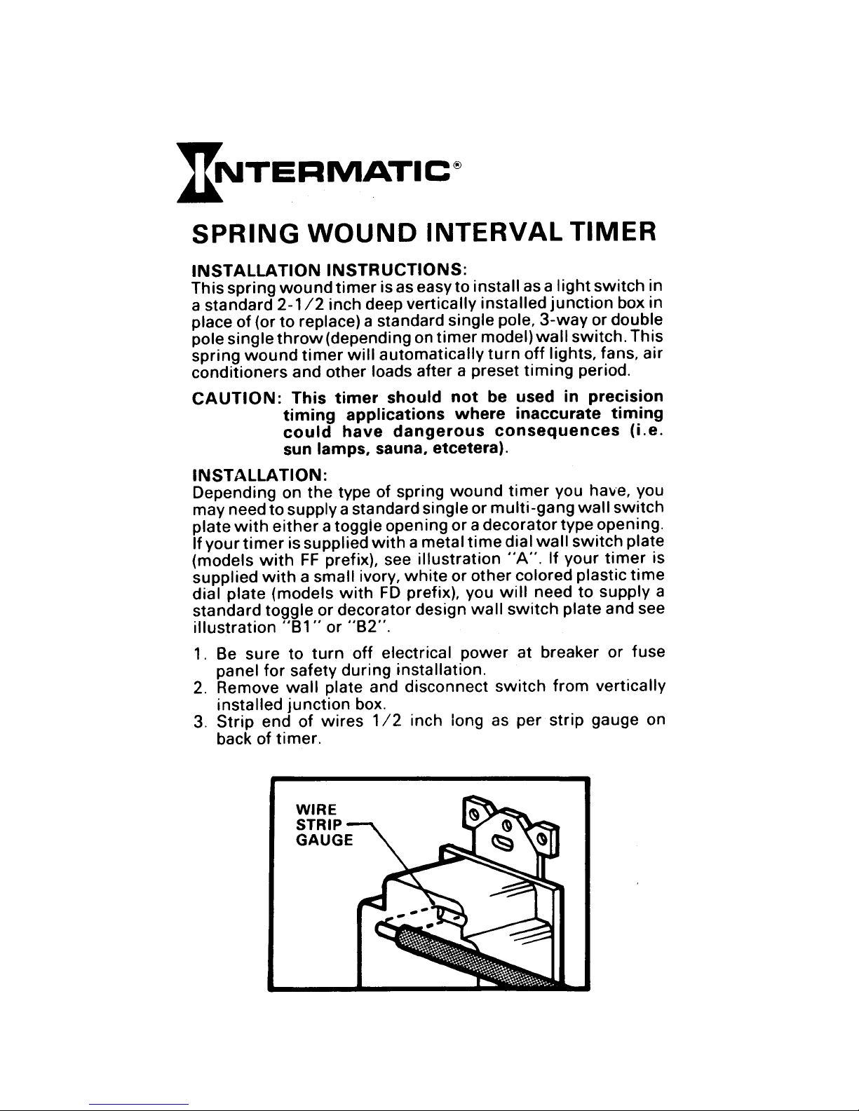
Strip
3.
back
for
end
of
turn
to
safety
wall
junction
of
timer.
WIRE
STRIP
GAUGE
off
during
plate
box.
wires
electrical
installation.
and disconnect
inch long
1/2
power
at breaker
switch
as per
from
strip
fuse
or
vertically
gauge on
Page 2
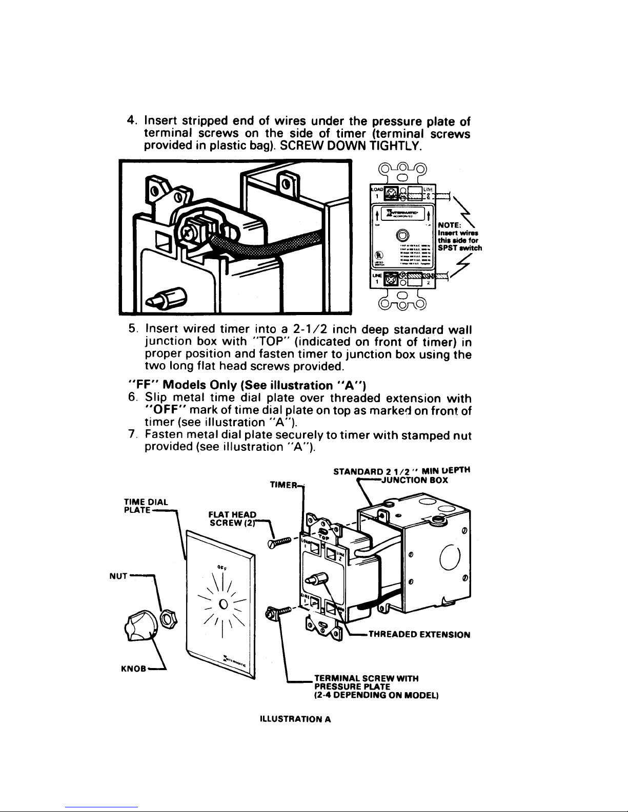
4.
Insert stripped end
terminal
provided in
5.
Insert
junction
proper position and fasten
two
wired
long
screws on
plastic
box
flat
head screws provided.
bag). SCREW
timer
with
of
wires
the
into a
"TOP"
under
side
2-1/2
(indicated on
timer
the
of
timer
DOWN TIGHTLY.
inch deep standard
to
junction
pressure
(terminal
tl~lt
-
front
box using
plate
screws
..
of
timer) in
of
wall
the
"FF"
6.
7.
TIME DIAL
PLATE
Models
Slip metal
"OFF"
timer
Fasten metal dial plate securely
provided (see
(see illustration
Only
time
mark of time dial plate on top as marke1 on
(See
illustration
dial plate
"A").
illustration
NUT"]
.~~
"A")
over threaded extension
to
timer
"A").
STANDARD 2
TERMINAL SCREW WITH
PRESSURE PLATE
(2-4
DEPENDING ON MODEL)
with
stamped
1/2"
JUNCTION BOX
THREADED
with
front
of
nut
MIN
UEPTH
0
EXTENSION
ILLUSTRATION
A
Page 3

Models
FD ..
..
Illustration
8.
on timer. do
NOTE:
If you are
is
it
1,
B
switch
the
securely hold
self-tapped
inward
self-tap
switch
metal
the
decorator
switch
the
Slip plastic
9.
OFF"
..
timer
NOT
and fasten
OVER
Only
"B"
using
necessary to use
not
pressure
into
plate,
tabs at the opposite ends
style plate
plate,
mark
(Illustration
- Place
not over tighten.
a standard
plate.
switch
the
the
into
while
timer
the
illustration
but
time
dial plate over threaded extension
time
of
securely
TIGHTEN.
standard toggle or decorator plate
toggle
nut
The
plate.
timer
turning
body.
82
using
not
do
dial plate
to
(See
body and
threaded
the
81 and
two
the
provided
The screws,
the
using a decorator style
If
two
over
on top as marked on
timer
illustration
82)
switch
screw
of
plate,
screws provided
with
will
holes
the
screws provided
the
used,
if
require a
firmly
are provided in
timer. Fasten
tighten.
provided.
nut
with
"8").
illustration
timer
in order
with
will
must
gentle
wall
with
with
front
DO
be
to
the
of
ILLUSTRATION
NUT7
~~
~
~~:
KNOB~~
LPLASTIC
TIME DIAL
PLATE
B1
STANDARD
'---SINGLE
NOT
TIMER
TOGGLE SWITCH
GANG
INCLUDED
(SHOWN)
WITH TIMER
STANDARD
OR
JUNCTION BOX
PLATE
MULTI-GANG
2
1/2
MIN
DEPTH
Page 4

ILLUSTRATION
SWITCH PLATE
REQUIRED (SUPPLIED WITH
SWITCH
PLATE)\
82
SCREW
(2)
Qlll"
o@e
;).
.......
L.LA~TIC
TIME DIAL
PLATE
10. Push knob on
"OFF"
which
11. Restore power.
on
dial
matches the
---.SINGLE
timer
DECORATOR SWITCH
NOT INCLUDED
GANG
(SHOWN)
shaft so knob pointer centers on
plate. The knob has a
"D"
shaft on the timer.
PLATE
"D"
OR
shaped
WITH TIMER
MULTI-GANG
hole
HOW
FOR
wise~
the
TO OPERATE
AUTOMATIC
to
end of preset
YOUR
TIMING
time
desired. Timer
timed
period. Note
for reverse action applications
preset
TO
Turn
does
returned
timing
BYPASS
counterclockwi~
not
period.
TIMER:
op,~rate,
to
...
OFF".
but
(Models
switch
APPLICATIONS:
The variety
spring
of
wound
pole configurations
timers to be used for many applications as
detailed to follow:
SPST
Used to break
• Coffee
•
Air
•
Lighting
•
Ventilating Fans
the
hot side of any 1
Pots
Conditioners
TIMER:
OPERATION:
will
turn
that
timers
will
turn
load
to
is
with
"ON"
"hold"
stop.
At
until
available
20
volt load such
Turn
"OFF"
"ON"
feature
this
position,
knob is
allow
timer
load
(SPOT)
at end of
only)
manually
lntermatic
as:
clock-
at
wired
-
timer
NEUTRAL
LOAD
LINE
1
1
HOT
Page 5

SPOT
For applications requiring 3-way switching
and 3-way switch) or reverse action applications. Reverse
action applications
limited time, after which the load
allow
a load to
be
will
Three way applications are used for controlling a load from
different locations such
as:
• Hallways
• Corridors
• Self-storage Facilities
• Upper Level/Lower Level
(2
timers or timer
turned
"OFF"
switch back
for a
"ON".
two
120
NO
V.A.C.
LOAD2
LOAD 1
3-Way
Reverse
Switching
LOAD2
---<>
LOAD 1
Action
Switching
DPST
For applications where both sides of a 208,
load must
• Large Horse Power Motors
• Pumps
• Indoor Lighting
• Outdoor Lighting
be
switched. Applications such
LINE 1
LINE2
as:
LINE1
LINE2
240
or 277 volt
LOAD 1
LOAD2
LINE1
LINE 2
240
V.A.C.
Page 6

SWITCH
1
2
20
1 0 Amps
1 0 Amps 277 V.A.C.
RATING
H.P.
at 125 V.A.C.
H.P.
at
250
SPECIFICATIONS:
V.A.C.
Amps 125 V.A.C.
150
V.A.C.
50/60
50/60
50/60
50/60
50/60
Hertz
Hertz
Hertz
Hertz
Hertz
7 Amps 125 V.A.C. Tungsten
The following models are currently available:
MAXIMUM
TIME
CYCLE
5 min
15 min
30min
60min
6
hr
12 hr
hr
2
hr
4
hr
6
12
hr
6
hr
12
hr
Change
time
decorator
For
or
contact
If
within
workmanship,
The
warranty
units
(b)
used in accordance
states do
warranty
This
from state to state.
This
warranty
the
unit
station listed below. Please be sure to
shipping damage. This
Grove,
prefix
dial and knob.
style
further
information,
lntermatic
one
(1
)year
from
lntermatic
does
not
which
not
allow a limitation
service is available by either
was
purchased,
Illinois
apply to: (a)damage caused by accident. abuse, mishandling, dropping;
have been subject to unauthorized repair, opened, taken apart;
with
gives you specific legal rights, and you may also have
warranty
60081-9698.
MODEL#
w/o
FF5M
FF15M
FF30M
FF60M
FF6H
FF12H
FF32H
FF34H
FF36H
FF312H
FF46H
FF412H
to
"FD"
Add
time
dial and knob.
directly
FULL ONE YEAR WARRANTY
the
date
of
Incorporated
directions,
or
AUTHORIZED SERVICE STATION
purchase,
(d)
of damages, so
(b)
mailing
is
made by
INTERMATIC INCORPORATED
4720
West
Chicago, Illinois 60641
HOLD
SPST
SPOT
DPST
for
decorator
"W"
see
suffix
your
local electrical
and request
this
will
damages exceeding
(a)
postage prepaid to
wrap
Montrose
product
repair or replace
the
foregoing
returning
the
product securely
lntermatic
Incorporated, lntermatic Plaza, Spring
Avenue
MODEL#
w/HOLD
FF5MH
FF15MH
FF30MH
FF60MH
FF6HH
FF12HH
FF32HH
FF34HH
FF36HH
FF312HH
FF46HH
FF412HH
style
for
fails
it
free of charge.
the
limitation
the
product to the dealer from
the
ivory
"white"
form
due to a defect in material or
cost
nearest authorized service
of
may
other
when
FD/FF.
the
not
rights
mailing
colored
colored
distributor
(c)
units
which
to avoid
not
vary
whom
product. Some
apply to you.
INTERMATIC
SPRING
158MT7677
GROVE,
INCORPORATED
ILLINOIS
60081-9698
PRINTED
IN
U.S.A.
 Loading...