

Page 1

OPERATING MANUAL
PROFESSIONAL POWER
AMPLIFIER
S3000/4000
Page 2

11
UNPACKING AND INSTALLATION
Although it is neither complicated to install nor difficult to operate your Power Amplifier, a few minutes of your
time is required to read this manual for a properly wired installation and becoming familiar with its many
features and how to use them. Please take a great care in unpacking your set and do not discard the carton
and other packing materials. They may be needed when moving your set and are required if it ever becomes
necessary to return your set for service. Never place the unit near radiators, in front of heating vents, to direct
sun light, in excessive humid or dusty location to avoid early damage and for your years of quality use.
Connect your complementary components as illustrated in the following page.
This symbol is intended to alert the user to the
CAUTION
RISK OF ELECTRIC SHOCK
DO NOT OPEN
presence of uninsulated “dangerous voltage” within
the product’s enclosure that may be of sufficient
magnitude to constitute a risk of electric shock to
persons.
CAUTION: TO REDUCE THE RISK OF ELECTRIC SHOCK.
DO NOT REMOVE COVER (OR BACK).
NO USER-SERVICEABLE PARTS INSIDE.
REFER SERVICING TO QUALIFIED SERVICE PERSONNEL.
WARNING
To prevent fire or shock hazard, do not
expose the unit to rain or moisture.
This symbol is intended to alert the user to the
presence of important operation and maintenance
(servicing) instructions in the literature accompanying
the appliance.
Caution: To prevent electric shock do not use this (polarized) plug with
an extension cord, receptacle or other outlet unless the blades
can be fully inserted to prevent blade exposure.
Attentions: Pour prévenir les chocs électriques ne pas utiliser cette fiche
polarisée avec un prolongateur, une prise de courant on une
autre sortie de courant, sauf si les lames peuvent étre
insérées à fond sans en laisser aucune partie à découvert.
Page 3

FEATURES
HIGH PERFORMANCE POWER AMPLIFIER WITH SMPS SYSTEM
Adopting high efficient switching mode power supply, the amplifier is possessed of high power performance
with reliability, and its weight is light.
DUAL MONORAL POWER SUPPLY
The amplifier is operated by independently power supply for each channel. If one channel is break down,
another channel can be perform well.
REMOTE POWER ON/OFF CONTROL (STAND-BY)
HIGH EFFICIENCY CIRCUIT TYPE
High efficient 3-step(S4000) output circuit for lower AC current consumption and advanced thermal
performance. (S3000:2-step output circuit)
VARIOUS LED INDICATORS
To confirm the operating status, LED display of Power, Stand-By, Signal, Level, Clip and Protection on front
panel.
VARIOUS PROTECTION CIRCUITS
To insure stability against over current, over heating, output short, turn on/off delay, RF protection, cliplimiter, DC fault detection power supply shutdown circuitry is provided.
22
MODE SELECTOR SWITCH
Operating Modes are PARALLEL, STEREO and BRIDGED-MONO.
VARIABLE FAN COOLING METHOD
Continuously variable speed fan for silent operation (Air flow: from rear to front).
Page 4
33
4000
S
PROFESSIONAL POWER AMPLIFIER
CLIP
-10dB
-20dB
SIGNAL
CLIP LIMITER10111213141618212780012345678900
1112131517192229541001234567890
0
1045
CHANNEL 2
CHANNEL 1
PROTECT
STANDBY
POWER
POWER
1011121314161821278001234567890
0
1112131517192229541001234567890
0
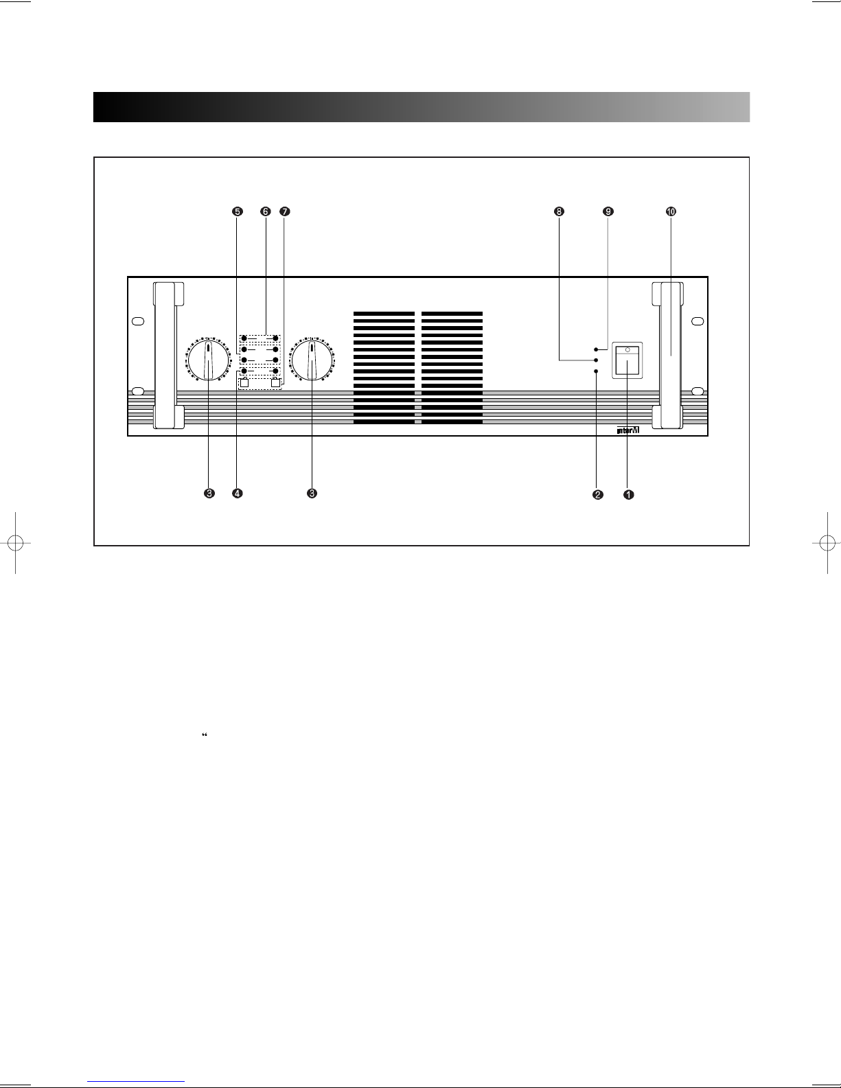
FRONT PANEL CONTROLS
1. POWER SWITCH
Use this to power the amplifier on or off.
2. POWER INDICATOR
Power indicator is driven by power switch, and the LED turns on when the amplifier is powered ON.
3. LEVEL CONTROLS
Separate level controls allow you to adjust the input level of the arriving at the rear panel input connectors.
At the fully counterclockwise position, the signal is infinitely attenuated. At the fully clockwise position, and
signal is at unity gain. When 1Vrms of signal arrives at the input connectors and the channel input controls
are set to their
MAX” position, the amplifier delivers full power output.
4. SIGNAL INDICATORS
The signal indicators turn on brightly when 1 watt signal level is present in the output.
5. OUTPUT LEVEL INDICATORS
The output level indicators turn on when amplifier has been turned on and has power. These LEDs turn on
when -20dB and -10dB signal level below rated output power is present in the output.
Page 5

6. CLIP-LIMITER INDICATORS
The clip-limiter indicators turn on when a distortion level above 1% THD is present in the output.
7. CLIP-LIMITER SWITCHES
Use this to prevent the amplifier from continuous clipping in each channel output.
8. STAND-BY INDICATOR
The stand-by indicator turns on when the stand-by switch (2p screw terminal) on rear panel turned on.
9 PROTECTION INDICATOR
The protection indicator turns on when a protection circuit in the amplifier is operating by an abnormal
condition as follows.
* Thermal protection....................When the heatsink and main switching power transformer
temperature should climb above 100
* Full short protection ........................The output circuit protects the output devices from short circuits and
stressful loads.
* DC fault protection ..........................The outputs will mute if DC or excessive subsonic energy appears at
them.
* RF protection...............................The input circuits are isolated by 10KΩ resistors. An supersonic
network decouples RF from the outputs and helps keep the amplifier
stable with reactive loads.
* Turn on/off muting ...........................Turn on/off muting blocks transients from the amplifier or preceding
devices from reaching the speakers. The turn on delay has been
extended somewhat, and turn off muting.
* Clip limiting ...................................During normal operation, the clip limiter does not affect the audio
signal and is, in fact, inaudible. It will allow brief clipping of peaks,
activating only when continuous, hard limiting occurs. The clip limiter
will then gradually reduce the audio signal (up to 10dB) to minimize
clipping. When clipping ends, the clip limiter will deactivate and cease
its gain reduction.
* Inrush current protection.................ln rush current is limited by an NTC resistor (Negative Temperature
Coefficient) which starts at a high resistance and then diminishes
after turn on to avoid loss of power.
, protection circuit is operated.
44
10. HANDLES
You can handle the amplifier easily by using these handles.
Page 6

55
S/N
PROFESSIONAL POWER AMPLIFIER
MODEL NO : S-4000
MADE IN KOREA
~AC INPUT
230V 50Hz
4100W
BRIDGE
PARALLEL
STEREO
CH 2
CH 1
(+)
(-)
OUTPUT
(-)D(+)BRIDGEMONO
(+)
(-)
STANDYBY+ENABLE
+
POWER SUPPLY
CONTROL
PUSH
PUSH
PUSH
PUSH
INPUT
CH 2
CH 1
CH 1
CH 2
SPEAKON CON.
(STEREO)
1+:POSITIVE
1-:GND
2+,2-:NOT CONNECT
SPEAKON CON.
(BRIDGED MONO)
1+:(CH 1)
1+:(CH 2)
CAUTION;
TO REDUCE THE RISK OF ELECTRIC SHOCK,
DO NOT REMOVE COVER. NO USER SERVICEABLE PARTS INSIDE.
REFER SERVICING TO QUALIFIED SERVICE PERSONNEL.
AVIS;
RISQUE DE CHOC ELECTRIOUE NE PAS OUVRIR.
20K BALANCED
10K UNBALANCED
INPUT SENSITIVITY : 0dBV
INPUT IMPEDANCE
PUSH
2
1
3
HOT GROUND
COLD
PUSH
2
1
3
HOTGROUND
COLD
REAR PANEL CONTROLS
1. AC INPUT
Plug this AC input cord into AC outlet.
2. INPUT TERMINALS (CHANNEL 1, 2)
Input connectors are provided both balanced combination jacks.
Channel 1 input terminal is used in Bridge mode and parallel mode.
XLR-TYPE CONNECTION
They are wired pin 1-ground, pin 2-hot(+), and pin 3 cold(-)
GROUND
PHONE JACK
They are wired tip-hot(+), ring-cold(-), and sleeve-ground.
XLR-MAIL
FOR LINK
HOT
COLD
COLD
COMBINATION
HOT
FOR INPUT
GROUND
COLD
GROUND
GROUND HOT
HOT
Page 7

3. MODE SELECTOR
CH 1
CH 2
CH 1
CH 2
CH 1
CH 2
By the mode select switch, these amplifier can be used for stereo, input parallel and bridged mono
function.
1) PARALLEL MODE 3) BRIDGED MONO MODE
66
4. OUTPUT TERMINALS
Output terminals are dual five-way binding posts and speaker connectors. Do not parallel the two outputs
of each channel by connecting them (together, or parallel them) with any other amplifier output.
*When speakers are connected through speaker, please make sure correct connection of each pin, and
refer speaker pin number.
STEREO MODE BRIDGED MODE
B
R
I
D
G
E
D
(+)
M
O
N
O
(-)
(+) (-)
CH 1
(+) (-)
CH 2
OUTPUT
AMP OUTPUT CH 1, CH 2
1- 1+
2+ 2-
NOT CONNECTED
B
R
I
D
G
E
D
(+)
M
O
N
O
(-)
(+) (-)
CH 1
(+) (-)
CH 2
OUTPUT
NOT CONNECTED
1- 1+
2+ 2-
MONO(BTL)
CH 1 OR CH 2
The minimum impedance for the connected speaker system is specified in “Speaker Impedance” on page8.
*OUTPUT CONNECTORS(BINDING POST)
Use these to connect the amplifier to loudspeakers, wiring method is as fallows.
1)Stereo mode: RED (CH1&2) : HOT
BLACK (CH1&2) : COLD
2)Bridged mono mode: RED (CH1) : HOT
BLACK (CH2) : COLD
BLACK (CH1&2) : USELESS TERMINAL
Page 8

77
STANDYBY
ENABLE
POWER SUPPLY
CONTROL
+
+
STANDYBY
ENABLE
POWER SUPPLY
CONTROL
STANDYBY
ENABLE
+
+
+
+
POWER SUPPLY
CONTROL
5. STAND-BY SWITCH
Use this to stand-by the amplifier for power supply control.
1) ONE AMPLIFIER
External Switch
2) MULTIPLE AMPLIFIER
6. FAN
Continuously variable speed fan is operated by the thermal sensors on the main heatsink or the switching
power transformer.
External Switch
Page 9

88
(+)
(-)
OUTPUT
(-)D(+)BRIDGEMONO
(+)
(-)
CH 2
CH 1
CH 1
CH 2
SPEAKON CON.
(STEREO)
1+:POSITIVE
1-:GND
2+,2-:NOT CONNECT
SPEAKON CON.
(BRIDGED MONO)
1+:(CH 1)
1+:(CH 2)
(4Ω min)
(4Ω min)
(8Ω min)
(8Ω min)
(8Ω min)
(8Ω min)
BRIDGE
PARALLEL
STEREO
(+)
(-)
OUTPUT
(-)D(+)BRIDGEMONO
(+)
(-)
CH 2
CH 1
CH 1
CH 2
SPEAKON CON.
(STEREO)
1+:POSITIVE
1-:GND
2+,2-:NOT CONNECT
SPEAKON CON.
(BRIDGED MONO)
1+:(CH 1)
1+:(CH 2)
(4Ω min)
(4Ω min)
BRIDGE
PARALLEL
STEREO
(+)
(-)
OUTPUT
(-)D(+)BRIDGEMONO
(+)
(-)
CH 2
CH 1
CH 1
CH 2
SPEAKON CON.
(STEREO)
1+:POSITIVE
1-:GND
2+,2-:NOT CONNECT
SPEAKON CON.
(BRIDGED MONO)
1+:(CH 1)
1+:(CH 2)
BRIDGE
PARALLEL
STEREO
(+)
(-)
OUTPUT
(-)D(+)BRIDGEMONO
(+)
(-)
CH 2
CH 1
CH 1
CH 2
SPEAKON CON.
(STEREO)
1+:POSITIVE
1-:GND
2+,2-:NOT CONNECT
SPEAKON CON.
(BRIDGED MONO)
1+:(CH 1)
1+:(CH 2)
BRIDGE
PARALLEL
STEREO
(+)
(-)
OUTPUT
(-)D(+)BRIDGEMONO
(+)
(-)
CH 2
CH 1
CH 1
CH 2
SPEAKON CON.
(STEREO)
1+:POSITIVE
1-:GND
2+,2-:NOT CONNECT
SPEAKON CON.
(BRIDGED MONO)
1+:(CH 1)
1+:(CH 2)
(8Ω min)
BRIDGE
PARALLEL
STEREO
(8Ω min)
(+)
(-)
OUTPUT
(-)D(+)BRIDGEMONO
(+)
(-)
CH 2
CH 1
CH 1
CH 2
SPEAKON CON.
(STEREO)
1+:POSITIVE
1-:GND
2+,2-:NOT CONNECT
SPEAKON CON.
(BRIDGED MONO)
1+:(CH 1)
1+:(CH 2)
(8Ω min)
BRIDGE
PARALLEL
STEREO
STEREO MODE AND BRIDGED MONO MODE
STEREO MODE
In this mode, channels 1 and 2 operate independently (typical stereo amplifier). Channel 1 input signal
feeds channel 1 power amp, and channel 2 input signal feeds channel 2 power amp. In this mode, the
minimum speaker impedance per channel is 4Ω.
BRIDGED MONO MODE
In this mode, channels 1 and 2 are bridged together and work as one mono amplifier. In this mode, the
minimum speaker impedance is 8Ω.
SPEAKER IMPEDANCE AND CONNECTION
The series amplifier has three operating modes: Stereo, Bridged and Parallel and allows you to connect
multiple speaker systems in parallel. Therefore, the minimum speaker impedance various depending on the
combination of these speakers. Be sure that the speaker impedance falls below the specified impedance.
The figures below show the examples of connection is Stereo mode and Bridged mode, and speaker systems
connected in parallel in Stereo mode, and the respective minimum impedance.
STEREO MODE CONNECTIONS BRIDGED MODE CONNECTIONS
Page 10

99
10mm
CAUTION FOR SPEAKER CONNECTION AND INSTALLATION
1. Turn off the POWER switch.
2. After removing approx. 10mm of insulation from the ends of the speaker cables, pass the bartends of the
speaker wires through the holes in the corresponding speaker terminals and tighten the terminals to
securely clamp the wires.
Refer to page 6 for speaker polarity.
At the time make sure that the bare ends of the speaker cables do not extend from the terminals in such a
way that they touch the chassis.
Wire should not
touch the chassis
3. SPEAKER CABLE
If you use a long speaker cable, use as thick a cable as possible to prevent deterioration of the damping
factor or power loss inside the cable. Even the thickest cable can be used for the speaker terminal of this
unit.
4. The amplifier are capable of hazardous output voltage. To avoid electrical shock when using the Binding
Posts for speaker connections, do not touch exposed speaker wiring while the amplifier is operating.
5. To avoid damage to the amplifier mounting ears and/or rack rails, the amplifier must be supported at all
four corners when used in portable racks.
6. AIR FLOW
The amplifier intakes cool air through the rear panel and exhausts warm air out the front panel. When
mounting amplifiers in a portable rack, make sure the rear panel is completely open for ventilation.
7. To reduce temperature of amplifier in rack, use to blank panel between the two amplifier.
Page 11

CONNECTIONS
BRIDGE
PARALLEL
STEREO
CH 2
CH 1
(+)
(-)
OUTPUT
(-)D(+)BRIDGEMONO
(+)
(-)
STANDYBY+ENABLE
+
POWER SUPPLY
CONTROL
PUSH
PUSH
PUSH
PUSH
INPUT
CH 2
CH 1
CH 1
CH 2
SPEAKON CON.
(STEREO)
1+:POSITIVE
1-:GND
2+,2-:NOT CONNECT
SPEAKON CON.
(BRIDGED MONO)
1+:(CH 1)
1+:(CH 2)
BRIDGE
PARALLEL
STEREO
CH 2
CH 1
(+)
(-)
OUTPUT
(-)D(+)BRIDGEMONO
(+)
(-)
STANDYBY+ENABLE
+
POWER SUPPLY
CONTROL
PUSH
PUSH
PUSH
PUSH
INPUT
CH 2
CH 1
CH 1
CH 2
SPEAKON CON.
(STEREO)
1+:POSITIVE
1-:GND
2+,2-:NOT CONNECT
SPEAKON CON.
(BRIDGED MONO)
1+:(CH 1)
1+:(CH 2)
BRIDGE
PARALLEL
STEREO
CH 2
CH 1
(+)
(-)
OUTPUT
(-)D(+)BRIDGEMONO
(+)
(-)
STANDYBY+ENABLE
+
POWER SUPPLY
CONTROL
PUSH
PUSH
PUSH
PUSH
INPUT
CH 2
CH 1
CH 1
CH 2
SPEAKON CON.
(STEREO)
1+:POSITIVE
1-:GND
2+,2-:NOT CONNECT
SPEAKON CON.
(BRIDGED MONO)
1+:(CH 1)
1+:(CH 2)
AUDIO MIXER
~AC INPUT
220V 60Hz, 12W
FUSE
0.08A/250V
STEREO/MONO
LOW
HIGH
INPUT 2
GROUND
FRAME FLOAT
MID
HIGH
MONO SUBWOOFER
LOW
HIGH
INPUT 1
LOW
INPUT
STEREO
MONO
S/N
DIV-9123
~AC INPUT
220V 60Hz, 12W
FUSE
0.08A/250V
STEREO/MONO
LOW
HIGH
INPUT 2
MID
HIGH
MONO SUBWOOFER
LOW
HIGH
INPUT 1
LOW
INPUT
STEREO
MONO
S/N
DIV-9123
R
L
SPEAKER L
TWEETER
MID RANGE
WOOFER
SPEAKER R
TWEETER
MID RANGE
WOOFER
MIC
CASSETTE DECK
GUITAR
GROUND
FRAME FLOAT
3 WAY CONNECTION
1100
Page 12

1111
BRIDGE
PARALLEL
STEREO
CH 2
CH 1
(+)
(-)
OUTPUT
(-)D(+)BRIDGEMONO
(+)
(-)
STANDYBY+ENABLE
+
POWER SUPPLY
CONTROL
PUSH
PUSH
PUSH
PUSH
INPUT
CH 2
CH 1
CH 1
CH 2
SPEAKON CON.
(STEREO)
1+:POSITIVE
1-:GND
2+,2-:NOT CONNECT
SPEAKON CON.
(BRIDGED MONO)
1+:(CH 1)
1+:(CH 2)
BRIDGE
PARALLEL
STEREO
CH 2
CH 1
(+)
(-)
OUTPUT
(-)D(+)BRIDGEMONO
(+)
(-)
STANDYBY+ENABLE
+
POWER SUPPLY
CONTROL
PUSH
PUSH
PUSH
PUSH
INPUT
CH 2
CH 1
CH 1
CH 2
SPEAKON CON.
(STEREO)
1+:POSITIVE
1-:GND
2+,2-:NOT CONNECT
SPEAKON CON.
(BRIDGED MONO)
1+:(CH 1)
1+:(CH 2)
AUDIO MIXER
R
L
SPEAKER
SPEAKER
SPEAKER
SPEAKER
AUDIO MIXER
R
L
MIC
GUITAR
BRIDGE
PARALLEL
STEREO
CH 2
CH 1
(+)
(-)
OUTPUT
(-)D(+)BRIDGEMONO
(+)
(-)
STANDYBY+ENABLE
+
POWER SUPPLY
CONTROL
PUSH
PUSH
PUSH
PUSH
INPUT
CH 2
CH 1
CH 1
CH 2
SPEAKON CON.
(STEREO)
1+:POSITIVE
1-:GND
2+,2-:NOT CONNECT
SPEAKON CON.
(BRIDGED MONO)
1+:(CH 1)
1+:(CH 2)
CONNECTIONS
SINGLE AMP CONNECTION
BRIDGED MONO MODE CONNECTION
Page 13

1122
SPECIFICATIONS
ELECTRICAL
Rated Output Power (1 KHz, 1 % THD)
8Ω (per channel)...........................................................................................S3000:750W, S4000:1000W
4Ω (per channel) ........................................................................................S3000:1200W, S4000:1600W
2Ω (per channel)........................................................................................ S3000:1500W, S4000:2000W
8Ω (bridged mono.......................................................................................S3000:2100W, S4000:2800W
4Ω (bridged mono)......................................................................................S3000:3000W, S4000:4000W
Input Sensitivity..................................................................................................................................1 Vrms
T.H.D....................................................................................................................................Less than 0.1%
Frequency Response ................................................................................................20Hz-20KHz, 0.5dB
S/N................................................................................................................................... Less than -100dB
Channel Separation............................................................................................................Less than -80dB
Damping Factor.................................................................................................................Greater than 500
Indicators
Power LED.......................................................................................................................................Green
Stand-by LED...................................................................................................................................Yellow
Protect LED.........................................................................................................................................Red
Signal LED.......................................................................................................................................Green
Level LED (-20dB) ...........................................................................................................................Yellow
Level LED (-10dB) ...........................................................................................................................Yellow
Clip LED ..............................................................................................................................................Red
Input Impedance.....................................................................................................................10KΩ UNBAL
....................................................................................................................................................20KΩ BAL
Connectors
Input Connectors..........................................................................................XLR Jack, Combination Jack
Output Connectors.........................................................................................Speakon jack, Binding Post
Protection Circuits................................................................................................Full short circuit, RF-Port,
....................................................................................................................DC-fault, Thermal limiting/Muting,
.............................................................................................................................ON/OFF muting, Clip-limiter
Power Supply System.....................................................................SMPS (Switching Mode Power Supply)
Output Circuit..........................................................................................2 step high efficient circuit(S3000)
...................................................................................................................3 step high efficient circuit(S4000)
Cooling Method...................................................Continuous variable speed fan, air flow from rear to front
GENERAL
Power Source........................................................................................................AC 110V~240V, 50/60Hz
Power Consumption......................................................................................S3000:3400W, S4000:4100W
Weight.................................................................................................................S3000:17Kg, S4000:18Kg
Dimensions........................................................................................................482(W)x132(H)x437(D)mm
*Specifications and design subject to change without notice for improvements.
Page 14

MADE IN KOREA
 Loading...