

Page 1

Operation Manual
System Remote MIC Station/
12Key MIC Station Keypad
RM-6024/RM-6012KP
Page 2
SYSTEM REMOTE MIC STATION/12KEY MIC STATION KEYPAD
Welcome
Welcome
A personal welcome to you from the management and employees of Inter-M
All of the co-workers here at Inter-M are dedicated to providing excellent products with inherently good value,
and we are delighted you have purchased one of our products.
We sincerely trust this product will provide years of satisfactory service, but if anything is not to your complete
satisfaction, we will endeavor to make things right.
Welcome to Inter-M, and thank you for becoming part of our worldwide extended family!
This symbol is intend ed to aler t the user to the
CAutION
RISK OF ELECTRIC SHOCK
DO NOT OPEN
CAUTION: TO REDUCE THE RISK OF ELECTRIC SHOCK.
DO NOT REMOVE COVER (OR BACK).
NO USER-SERVICEABLE PARTS INSIDE.
REFER SERVICING TO QUALIFIED SERVICE PERSONNEL.
Caution: To prevent electric shock do not use this (polarized) plug with
Attentions: Pour prévenir les chocs électriques ne pas utiliser cette
WARNING
To prevent fire or shock hazard, do not
expose the unit to rain or moisture.
*WARNING FOR YOUR PROTECTION PLEASE READ THE FOLLOWING-WATER AND MOISTURE: Unit should not be used near water(e.g.
near a bathtub, washbowl, kitchen sink, laundry tub, in a wet basement, or near a swimming pool, etc). Care should be taken so than objects do
not fall and liquids are not spilled into the enclosure through openings.
*CLASS 2 WIRING (Adjacent to speaker terminal): The speaker output of this apparatus can exceed 10 Watts and could be a shock injury.
Connection to speakers should be performed by a skilled person.
*Do not install this equipment in a confined space such as a book case or similar unit.
*This apparatus shall not be exposed to dripping or splashing and no objects filled with liquids, such vases, shall be placed on the apparatus.
*This apparatus shall be connected to a mains socket outlet with a protective earthing connection.
It has heed to be easy to disconnect the device. To disconnect the device from power, separate AC input cable from inlet or unplug the AC Cord.
*
*
The socket-outlet shall be installed near the equipment and shall be easily accessible.
CAutION
*These servicing instructions are for use by qualified service personnel only. To reduce the risk of electric shock, do not perform any servicing
other than that contained in the operating instructions unless you are qualified to do so.
NOtE
*This equipment has been tested and found to comply with the limits for a Class A digital device, pursuant to Part 15 of the FCC Rules. These limits are
designed to provide reasonable protection against harmful interference when the equipment is operated in a commercial environment. This equipment
generates, uses, and can radiate radio frequency energy and, if not installed and used in accordance with the instruction manual, may cause harmful
interference to radio communications. Operation of this equipment in a residential area is likely to cause harmful interference in which case the user will
be required to correct the interference at his own expense.
presence of uninsulated “dangerous voltage” within
the prod uct’s enclos ure t hat m ay be of suffi cient
magnitude to constitute a risk of electric shock to
persons.
This symbol is intend ed to aler t the user to the
presence of important operation and maintenance
(servicing) instructions in the literature accompanying
the appliance.
an extension cord, receptacle or other outlet unless the blades
can be fully inserted to prevent blade exposure.
fiche polarisée avec un prolongateur, une prise de courant
on une autre sortie de courant, sauf si les lames peuvent
étre insérées à fon d sa ns en laisser auc une par tie à
découvert.
Page 3

SYSTEM REMOTE MIC STATION/12KEY MIC STATION KEYPAD
Contents
Contents
Unpacking .......................................................................................................................................2
Installation
Environment....................................................................................................................................2
Important Safety Instructions.............................................................................................................2
Features............................................................................................................................................3
Equipment Setting and Checking.................................................................................................4
Front Panel ......................................................................................................................................7
Rear Panel .......................................................................................................................................9
Applications ..................................................................................................................................11
Block Diagram ..............................................................................................................................12
Specifications ................................................................................................................................13
Service............................................................................................................................................15
Procedures....................................................................................................................................15
Schematic.....................................................................................................................................15
Parts List .......................................................................................................................................15
Warranty .......................................................................................................................................15
"We, Inter-M to apply the appropriate set of E4 & Class A for Electromagnetic Environment Condition."
RM-6024/RM-6012KP
1
Page 4

SYSTEM REMOTE MIC STATION/12KEY MIC STATION KEYPAD
S
3125A
Unpacking
Unpacking
Although your RM-6024 is neither complicated nor difficult to operate, we recommend you take a few minutes
to read this brief manual and familiarize yourself with the important information regarding product features,
setup and operation.
As with most electronic devices, we strongly recommend you to retain the original packaging. In the unlikely
event the product must be returned for servicing, the original packaging (or reasonable equivalent) is required.
Installation
Installation
Environment
Never place this product in an environment which could alter its performance or reduce its service life. Such
environments usually include high levels of heat, dust, moisture, and vibration.
IMPORTANT SAFETY INSTRUCTIONS
1. Read these instructions.
2. Keep these instructions.
3. Heed all warnings.
4. Follow all instructions.
5. Do not use this apparatus near water.
6. Clean only with dry cloth.
7. Do not block any ventilation openings. Install in accordance with the manufacturer’s instructions.
8. Do not install near any heat sources such as radiators, heat registers, stoves, or other apparatus (including
amplifiers) that produce heat.
9. Do not defeat the safety purpose of the polarized or grounding-type plug. A polarized plug has two blades
with one wider than the other. A grounding type plug has two blades and a third grounding prong. The wide
blade or the third prong are provided for your safety. If the provided plug does not fit into your outlet, consult
an electrician for replacement of the obsolete outlet.
10. Protect the power cord from being walked on or pinched particularly at plugs, convenience receptacles, and
the point where they exit from the apparatus.
11. Only use attachments/accessories specified by the manufacturer.
12. Use only with the cart, stand, tripod, bracket, or table specified by the manufacturer, or sold with the apparatus.
When a cart is used, use caution when moving the cart/apparatus combination to avoid injury from tip-over.
13. Unplug this apparatus during lightning storms or when unused for long periods of time.
14. Refer all servicing to qualified service personnel. Servicing is required when the
apparatus has been damaged in any way, such as power-supply cord or plug is
damaged, liquid has been spilled or objects have fallen into the apparatus, the
apparatus has been exposed to rain or moisture, does not operate normally, or has
been dropped.
S3125A
2
RM-6024/RM-6012KP
Page 5

SYSTEM REMOTE MIC STATION/12KEY MIC STATION KEYPAD
Features
Features
Features
- ZONE MACRO FUNCTION
Zone one Macro Function exists for each button in the Inter-M PC Windows program allowing multiple zones to
be bundled into one single button. Maximum 160 zones per button.
- EXPANSION KEYPAD (RM-6012KP)
If an Expansion Keypad (RM-6012KP) is added, a total of 48 macro buttons can be used.
(Up to 2 Expansion Keypads can be connected)
- CHIME FUNCTION
Serves as the notification sound to announce a remote MIC broadcast.
- EXTERNAL AUX FUNCTION
Mixes an external sound source, so with MIC broadcasting, it can offer BGM capabilities.
- RS-422 COMMUNICATION
Allows remote mic (RM-6024) to be located up to a maximum distance of 1Km (3,280 feet) from RME-6108.
Note: It is recommended that remote mic (RM-6024) be located within 500m (1,640 feet) of RME-6108.
RM-6024/RM-6012KP
3
Page 6
SYSTEM REMOTE MIC STATION/12KEY MIC STATION KEYPAD
RM1
I
NPU
T
AUDIO
OU
T
AUDIO
OUT
RM2
I
NPU
T
RM1
INPUT
AUDIO
OU
T
AUDIO
OUT
RM2
INPUT
ϊۑ@Ţ۩م@ێԟێ@ۘڽ@Ĉڐ@Ê۾@ɜট۩ۉ@کێ@ۘںɩ@
࠭ҿșڽ@ّçǦ@ǷҜθ@ϊݖݖ@ψֲ֫٤N
܆Ͽࠤ@Z@REMOTE MIC EXTENDER
ЂʠϿ@Z
RME 6108
܄ÿۖͶ@Z
DC 24V, 150mA
܆
ܖۜϿ@
Z
ď
Öݖڜࣶ
TEL : 1588 7074
RM 1 RM 2 RM 3 RM 4 RM 5 RM 6 RM 7 RM 8
INPUT
OUTPUT
DC 24V
ϊۑ@Ţ۩م@ێԟێ@ۘڽ@Ĉڐ@Ê۾@ɜট۩ۉ@کێ@ۘںɩ@
࠭ҿșڽ@ّçǦ@ǷҜθ@ϊݖݖ@ψֲ֫٤N
܆Ͽࠤ@Z@REMOTE MIC EXTENDER
ЂʠϿ@Z
RME 6108
܄
ÿۖͶ@Z
D
C 24V, 150mA
܆ܖۜϿ@Z
ď
Öݖڜࣶ
TEL : 1588 7074
R
M 1 RM 2 RM 3 RM 4 RM 5 RM 6 RM 7RM 8
INPUT
OUTPUT
DC 24V
Equipment Setting and Checking
Equipment Setting and Checking
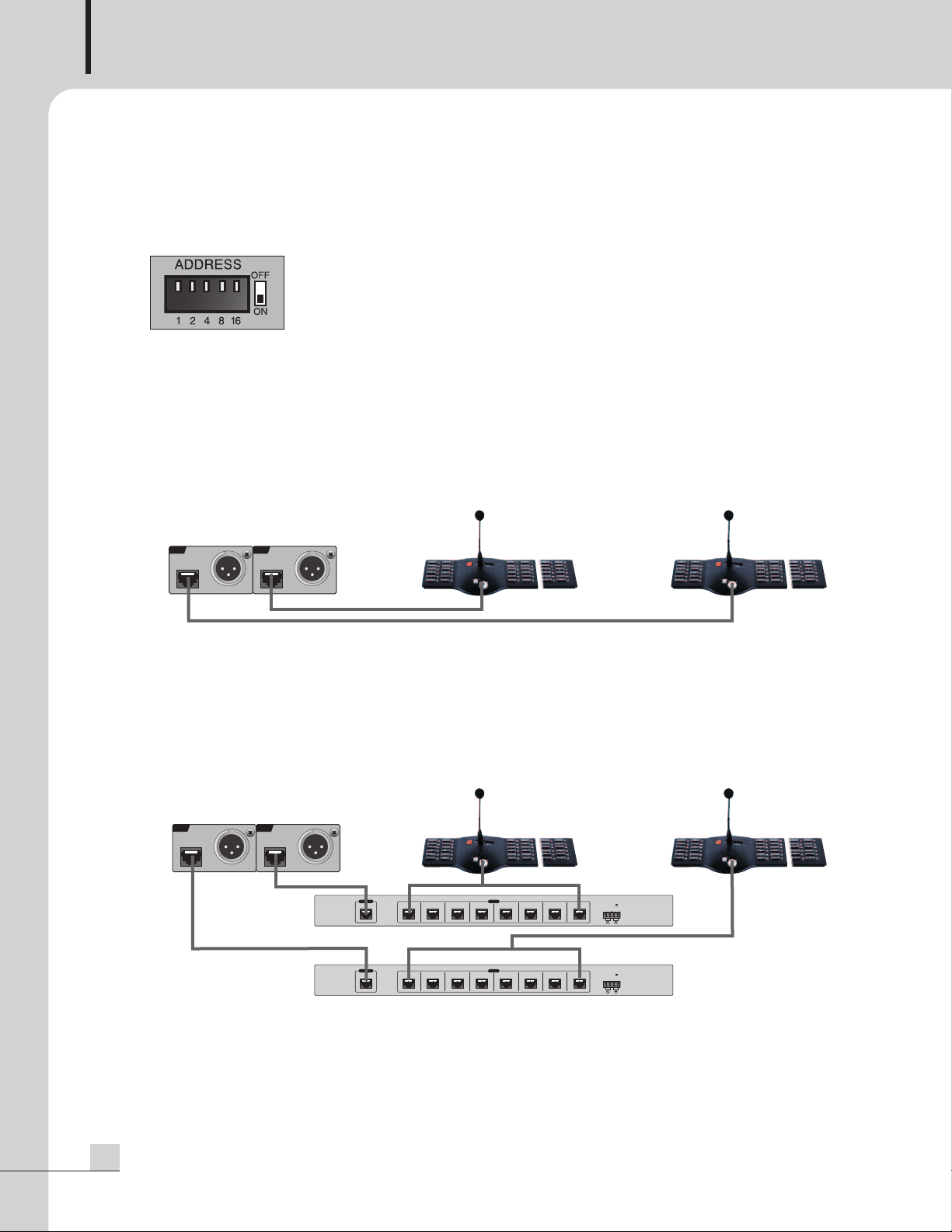
1. Address Switch Setting
1) Set the equipment number utilizing the rear panel DIP switch.
- If the equipment number is not set-up or is incorrect, all Zone Indicator LEDs will blink.
- If the number is already in-use, the FAULT LED will blink.
Please check the equipment number set-up status.
2) When connecting an RM-6024 directly to an ECS-6216P:
- The equipment number for the RM-6024 which is connected to RM1 terminal is labeled as “1”.
- The equipment number for the RM-6024 which is connected to RM2 terminal is labeled as “9”.
ECS-6216P
RM-1 RM-2
RM-6024 RM-6024
Set-up to No.9 for
equipment number
Set-up to No.1 for
equipment number
3) When connecting remote mics through an RME-6108 to an ECS-6216P:
- Choose numbers 1~8 for those remote mics which are connected to an RME-6108 using the RM1
terminal.
- Choose numbers 9~16 for those remote mics which are connected to an RME-6108 using the RM2
terminal.
If the above conditions are not followed or any number is used more than once, warning LEDs will blink.
ECS-6216P
RM-1 RM-2
RME-6108
RM-6024 RM-6024
Select equipment
number among 9~16.
number among 1~8.
Select equipment
RME-6108
4
RM-6024/RM-6012KP
Page 7

SYSTEM REMOTE MIC STATION/12KEY MIC STATION KEYPAD
4) The table below shows the set-up method, and if DATA number is added to switch turned ON, it will be
he equipment number.
t
Pin No. 12 3 45
Data 12 4 816
1 ON
2 ON
3 ON ON
4 ON
Address 5 ON ON
15 ON ON ON ON
16 ON
(Ex: When No. 1 and 3 is ON, add 1 and 4 which is actual corresponding number, and then equipment
number will be 5.)
RM-6024/RM-6012KP
5
Page 8

SYSTEM REMOTE MIC STATION/12KEY MIC STATION KEYPAD
A
B
LOCK
A
B
C
D
ῡ
ῡ
ῢ
ῢ
ΰ
2. Disassemble and Assemble of Side Pad (Required when expanding the keypad.)
※Dissemble the side pad
1. Unfasten the 3 screws in bottom.
2. Slightly pull up ① and ②, side pad will be
separated from the main body.
3. Pull out to ③, and side pad and main body will
separate.
※Assemble the side pad
1. Insert ① (lock) into ②.
2. Pull the side pad downward.
3. Fasten screws in bottom, and then complete the
assembly.
3. Assemble the expansion keypad (RM-6012KP)
- After dissembling the RM-6024 side pad, connect the RM-6012KP and internal connector.
- Assemble the RM-6024 and RM-6012KP using same instructions as above for side pad.
- Assemble the dissembled side pad in RM-6012KP.
6
RM-6024/RM-6012KP
Page 9

Front Panel
5 6 7 8 9
1 2 3 4
Front Panel
SYSTEM REMOTE MIC STATION/12KEY MIC STATION KEYPAD
1. ALL BUTTON
Used when broadcasting to all zones.
2. MIC
Condenser MIC.
3. OUTPUT LEVEL LED
Display the MIC output level.
4. POWER/FAULT/BUSY LED
- POWER LED (GREEN) : displays the power input status.
- FAULT LED (RED) : will be ON if communication error occurs.
- BUSY LED (RED) : will blink if there is any higher priority broadcast.
RM-6024/RM-6012KP
7
Page 10

SYSTEM REMOTE MIC STATION/12KEY MIC STATION KEYPAD
5. CHIME BUTTON
HIME button is operated only in TALK mode.
C
6. TALK ON/OFF BUTTON
Select the broadcasting zone(s), then push and release the TALK button to broadcast.
After finishing the broadcast, push the TALK button again to end the transmission.
7. ZONE DISPLAY LED AND LABEL
- Push the zone selecting button, and then corresponding LED (GREEN) will be ON.
- Zone information can be labeled and inserted.
8. ZONE SELECTION BUTTON
- Used when selecting the broadcasting zone.
- Multiple zones can be combined by using ZONE MACRO function for each button on PC Windows
program. (Maximum 160 zones per button)
- If expansion key pad (RM-6012KP) is added, a total of 48 MACRO buttons can be used. (Up to 2
expansion keypads (RM-6012KP) can be connected).
9. SIDE PAD
- After disassembling the side pad, the KEYPAD can be expanded by using RM-6012KP.
- Up to 2 expansion keypads (RM-6012KP) can be connected.
※Caution: When connecting an expansion keypad (RM-6012KP) to RM-6024, power should be off.
8
RM-6024/RM-6012KP
Page 11

Rear Panel
4 51 2 3
Rear Panel
SYSTEM REMOTE MIC STATION/12KEY MIC STATION KEYPAD
1. DC INPUT TERMINAL
- Power input terminal. Check polarity before connecting DC 24V.
- When connecting to PD (Power Distributor), connect to unswitched terminal.
2. ADDRESS SWITCH
Sets up the equipment number.
3. DATA & AUDIO TERMINAL (RJ-45)
Transmits the communication DATA and AUDIO signal.
PIN NO. Functions
1 RS-422 Data - TX+
2 RS-422 Data - TX3 RS-422 Data - RX4 Live Date
5 GND
6 RS-422 Data - RX+
7 Balanced Audio Output - HOT
8 Balanced Audio Output - COLD
RM-6024/RM-6012KP
9
Page 12

SYSTEM REMOTE MIC STATION/12KEY MIC STATION KEYPAD
4. MIC/AUX/CHIME VOLUME
CHIME Volume : adjust the CHIME output level.
-
- MIC Volume : adjust the MIC volume.
- AUX Volume : adjust the AUX volume.
5. AUX INPUT TERMINAL
Used when broadcasting through the RM-6024 with an external sound source. In this case, MIC and AUX
sound sources will be mixed and transmitted.
10
RM-6024/RM-6012KP
Page 13

RM1
I
NPUT
A
UDIO
OUT
A
UDIO
OUT
RM2
I
NPUT
LINK IN LINK OUT UPGRADE
S
OURCE 1
R
S 232
S
OURCE 2
EMG PANEL
/
A
DDRESS
1 2 3 4 5 6 7 8 9 10
1234 5678
9 10 11 12 13 14 15 16
1234 5678
9 10 11 12 13 14 15 16
TERM.
LOAD OPEN
12345678
9
10 11 12 13 14 15 16
FIRE
S
ENSOR
SPEAKER
OUTPUT
AMP
INPUT
HEHCEC EHCEHC EEH CEHCEHC HC HCHCHCHC HCHCHCHC
PD TIMER
EXTCOM
DC 24V
DC OUT
24V
MATRIX
12 0
S
IREN/VOLUME
PRE IN REMOTE IN 2 REMOTE IN 1 TIMER IN AUTO ANN IN PRE OUT
CONTROL OUT (TOAUTO ANN)
EXT INT
AUTO.ANN
REMOTE MIC
MIC SW
EXT INT
EP-6216
ECS-6216P
<ADDRESS SETTING: 9>
RM-6024 + RM-6012KP(x2)
++
<ADDRESS SETTING: 1>
RM-6024 + RM-6012KP(x2)
++
RM2RM1
Applications
Applications
SYSTEM REMOTE MIC STATION/12KEY MIC STATION KEYPAD
RM-6024/RM-6012KP
11
Page 14

SYSTEM REMOTE MIC STATION/12KEY MIC STATION KEYPAD
RS-422
RS-422
Block Diagram
Block Diagram
12
RM-6024/RM-6012KP
Page 15

SYSTEM REMOTE MIC STATION/12KEY MIC STATION KEYPAD
Specifications
Specifications
RM-6024
Channel 24CH
Communication Protocol RS-422(Maximum 1km/3,280 feet)
Audio
MIC INPUT SENSTIVITY -60dB
THD+N Less than 0.5%
FREQUENCY RESPONSE 120Hz ~ 20kHz
S/N Better than 50dB
AUX INPUT SENSTIVITY -10dB
THD+N Less than 0.5%
FREQUENCY RESPONSE 120Hz ~ 20kHz
S/N Better than 60dB
Operation Temperature -10°C ~ +40°C/14°F ~ 104°F
Power Source DC 24V
Weight (Set) 1.2kg/2.6lbs
Dimensions (Set) 456(W) x 65(H) x 200(D)mm/17.9(W)x2.5(H)x7.9(D)in
※Specifications and design are subject to change without notice.
RM-6024/RM-6012KP
13
Page 16

SYSTEM REMOTE MIC STATION/12KEY MIC STATION KEYPAD
65
199
456
120
137.5
※ DIMENSIONS
-RM-6024
-RM-6012KP
14
RM-6024/RM-6012KP
Page 17

SYSTEM REMOTE MIC STATION/12KEY MIC STATION KEYPAD
Service
Service
Procedures
Take steps to insure the problem is not related to operator error or other products within the system. Information
provided in the troubleshooting portion of this manual may help with this process. Once it is certain that the
problem is related to the product contact your warranty provider as described in the warranty section of this
manual.
Schematic
A Schematic is available by contacting your warranty provider.
Parts List
A Parts List is available by contacting your warranty provider.
Warranty
Warranty
Warranty terms and conditions vary by country and may not be the same for all products. Terms and conditions
of warranty for a given product may be determined first by locating the appropriate country which the product
was purchased in, then by locating the product type.
To obtain specific warranty information and available service locations contact Inter-M directly or the
authorized Inter-M Distributor for your specific country or region.
RM-6024/RM-6012KP
15
Page 18

NOTE
12
RM-6024/RM-6012KP
Page 19

RM-6024/RM-6012KP
13
Page 20

Inter-M, Ltd. (Korea) began operations in 1983.
Since then, Inter-M has grown to become one of the largest manufacturers
of professional audio and commercial sound electronics equipment in the world.
Inter-M has gained worldwide recognition for its own branded products,
as well as private label manufacturing of electronics sold under other names (OEM).
The company is no longer just a Korean company, but rather a global company
that is truly international in scope, with factories and offices in Korea and China,
and sales and marketing operations located in Japan, Europe, and the U.S.A.
With more than 850 employees around the globe,
Inter-M is well-poised for further growth and expansion.
Inter-M Americas, Inc.
13875 Artesia Blvd. Cerritos, CA 90703 USA
TEL : +1-562-921-0313, FAX : +1-562-921-0370
Home Page : http://www.inter-m.net, E-mail : info@inter-m.net
Inter-M Corporation
Seoul OFFICE:653-5 BANGHAK-DONG, DOBONG-KU, SEOUL, KOREA
TEL : +82-2-2289-8140~8, FAX : +82-2-2289-8149
Home Page : http://www.inter-m.com, E-mail : overseas@inter-m.com
MADE IN KOREA
January 2012 127749
 Loading...