

Page 1

Operation Manual
Reference Amplifier
R150 PLUS/300 PLUS/500 PLUS
* Rack mount products in the Western Hemisphere(North America, South America, and the Caribbean)
do not have handles installed due to customer preference.
Page 2

REFERENCE AMPLIFIER
Contents
Contents
Welcome
Warning.........................................................................................................................................1
Unpacking......................................................................................................................................2
Short Form Instructions.....................................................................................................................2
Installation
Environment....................................................................................................................................3
Important Safety Instructions.............................................................................................................3
Description.......................................................................................................................................4
Features............................................................................................................................................4
Accessories.....................................................................................................................................4
Front Panel ......................................................................................................................................5
E n g l i s h
Rear Panel .......................................................................................................................................6
Mounting in a Rack........................................................................................................................7
Applications
Stereo Installation............................................................................................................................8
Bridge Mono Installation ..................................................................................................................9
Linked Installation..........................................................................................................................10
Connections...................................................................................................................................11
Block Diagram ..............................................................................................................................13
Specifications ................................................................................................................................14
Service
Procedures....................................................................................................................................15
Schematic.....................................................................................................................................15
Parts List .......................................................................................................................................15
Variations and Options...............................................................................................................15
Warranty .......................................................................................................................................15
Page 3
REFERENCE AMPLIFIER
REFERENCE AMPLIFIER
Welcome
Welcome
A personal welcome to you from the management and employees of Inter-M
All of the co-workers here at Inter-M are dedicated to providing excellent products with inherently good value,
and we are delighted you have purchased one of our products.
We sincerely trust this product will provide years of satisfactory service, but if anything is not to your
complete satisfaction, we will endeavor to make things right.
Welcome to Inter-M, and thank you for becoming part of our worldwide extended family!
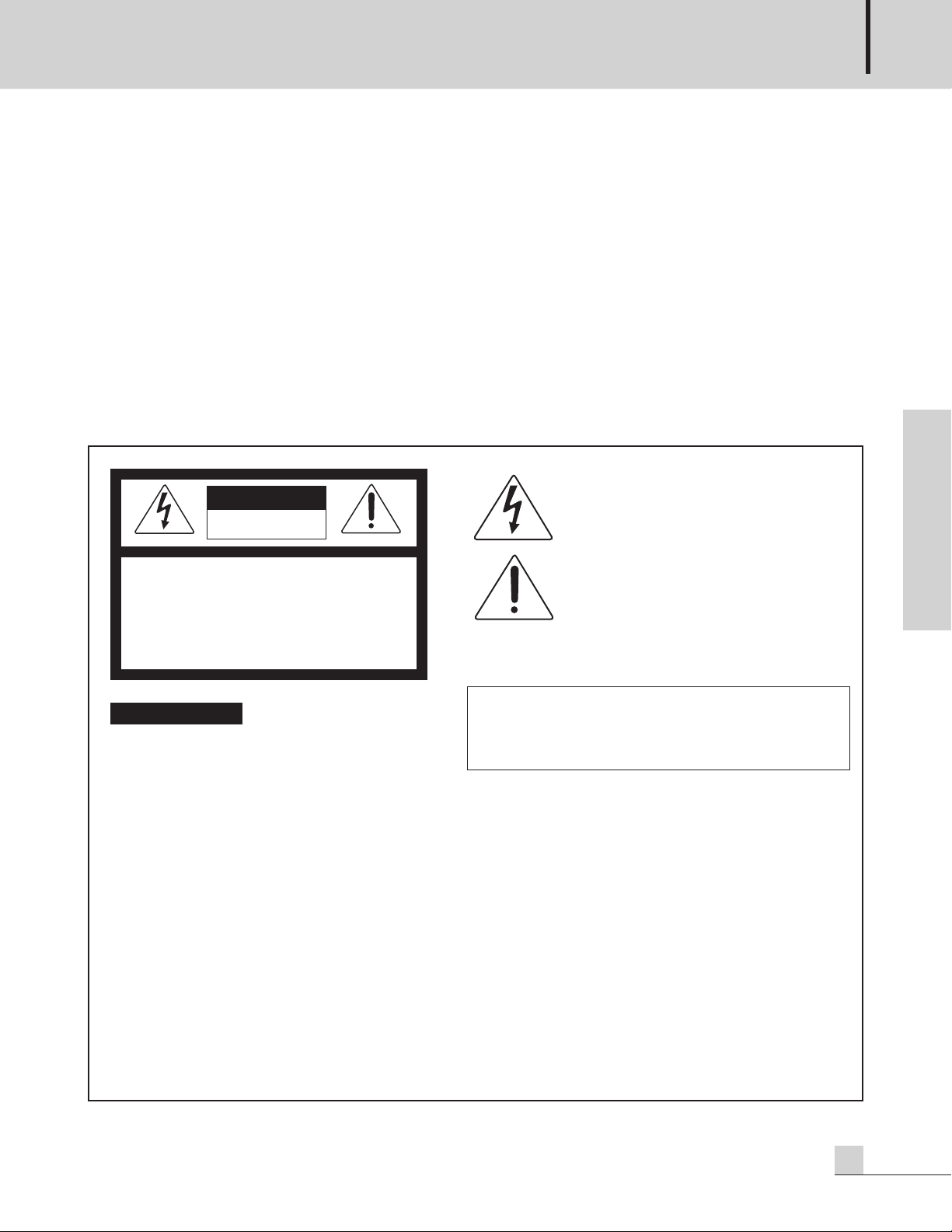
This symbol i s inten ded to alert the user to the
RISK OF ELECTRIC SHOCK
DO NOT OPEN
CAUTION: TO REDUCE THE RISK OF ELECTRIC SHOCK.
O NOT REMOVE COVER (OR BACK).
D
NO USER-SERVICEABLE PARTS INSIDE.
REFER SERVICING TO QUALIFIED SERVICE PERSONNEL.
Caution: To prevent electric shock do not use this (polarized) plug with
Attentions: Pour prévenir les chocs électriques ne pas utiliser cette
To prevent fire or shock hazard, do not
expose the unit to rain or moisture.
*WARNING FOR YOUR PROTECTION PLEASE READ THE FOLLOWING-WATER AND MOISTURE: Unit should not be used near water(e.g.
near a bathtub, washbowl, kitchen sink, laundry tub, in a wet basement, or near a swimming pool, etc). Care should be taken so than objects do
not fall and liquids are not spilled into the enclosure through openings.
*CLASS 2 WIRING (Adjacent to speaker terminal): The speaker output of this apparatus can exceed 10 Watts and could be a shock injury.
Connection to speakers should be performed by a skilled person.
*Do not install this equipment in a confined space such as a book case or similar unit.
*This apparatus shall not be exposed to dripping or splashing and no objects filled with liquids, such vases, shall be placed on the apparatus.
*This apparatus shall be connected to a mains socket outlet with a protective earthing connection.
It has heed to be easy to disconnect the device. To disconnect the device from power, separate AC input cable from inlet or unplug the AC Cord.
*
*These servicing instructions are for use by qualified service personnel only. To reduce the risk of electric shock, do not perform any servicing
other than that contained in the operating instructions unless you are qualified to do so.
This equipment has been tested and found to comply with the limits for a Class A digital device, pursuant to Part 15 of the FCC Rules. These limits are
designed to provide reasonable protection against harmful interference when the equipment is operated in a commercial environment. This equipment
generates, uses, and can radiate radio frequency energy and, if not installed and used in accordance with the instruction manual, may cause harmful
interference to radio communications. Operation of this equipment in a residential area is likely to cause harmful interference in which case the user will
be required to correct the interference at his own expense.
presence of uninsulated “dangerous voltage” within
the product’s enclosure that may be of sufficient
magnitude to constitute a risk of electric shock to
persons.
This symbol i s inten ded to alert the user to the
presence of important operation and maintenance
(servicing) instructions in the literature accompanying
the appliance.
an extension cord, receptacle or other outlet unless the blades
can be fully inserted to prevent blade exposure.
fiche polarisée avec un prolongateur, une prise de courant
on une autre sortie de courant, sauf si les lames peuvent
étre insérées à fond sans en l aisser aucune partie à
découvert.
E n g l i s h
R150 PLUS/300 PLUS/500 PLUS
1
Page 4

REFERENCE AMPLIFIER
Unpacking
Please take a few minutes to read this manual to familiarize yourself with important information regarding
installation, product features, and operation.
As with most electronic devices, ORIGINAL PACKAGING (OR EQUAL) IS REQUIRED in the unlikely event that
the product needs to be returned for servicing.
Short Form Instructions
1. Do not connect the AC power until step 6. The POWER switch should be in the OFF position.
2. Adjust both of the LEVEL controls to the fully attenuated position (turn counter-clockwise).
3. Connect an appropriate line level input signal to either the balanced XLR or the balanced 1/4" TRS (Tip-RingSleeve) connector marked INPUTS.
4. Move the MODE selector to the desired position. The Stereo position is the most common.
E n g l i s h
5. Connect the OUTPUTS to the speaker load according to the mode of operation determined in the previous step.
6. With the power switch in the OFF position, plug in the supplied Universal AC power cord to the product and
an appropriate AC source.
7. Depress the power switch to the ON position. The power switch will illuminate.
8. The product is ready for operation. Slowly increase the LEVEL control to the desired operating level. Avoid
illuminating the PEAK indicator and do not apply too much power to the speakers.
9. Operate the product and the system in a manner which DOES NOT illuminate the PEAK warning indicator.
2
R150 PLUS/300 PLUS/500 PLUS
Page 5

REFERENCE AMPLIFIER
S
3125A
Installation
Installation
Environment
Never place this product in an environment which could alter its performance or reduce its service life. Such
environments usually include high levels of heat, dust, moisture, and vibration.
IMPORTANT SAFETY INSTRUCTIONS
1. Read these instructions.
2. Keep these instructions.
3. Heed all warnings.
4. Follow all instructions.
5. Do not use this apparatus near water.
6. Clean only with dry cloth.
7. Do not block any ventilation openings. Install in accordance with the manufacturer’s instructions.
8. Do not install near any heat sources such as radiators, heat registers, stoves, or other apparatus (including
amplifiers) that produce heat.
9. Do not defeat the safety purpose of the polarized or grounding-type plug. A polarized plug has two blades
with one wider than the other. A grounding type plug has two blades and a third grounding prong. The wide
blade or the third prong are provided for your safety. If the provided plug does not fit into your outlet, consult
an electrician for replacement of the obsolete outlet.
10. Protect the power cord from being walked on or pinched particularly at plugs, convenience receptacles, and
the point where they exit from the apparatus.
11. Only use attachments/accessories specified by the manufacturer.
12. Use only with the cart, stand, tripod, bracket, or table specified by the manufacturer, or sold with the apparatus.
When a cart is used, use caution when moving the cart/apparatus combination to avoid injury from tip-over.
13. Unplug this apparatus during lightning storms or when unused for long periods of time.
14. Refer all servicing to qualified service personnel. Servicing is required when the
apparatus has been damaged in any way, such as power-supply cord or plug is
damaged, liquid has been spilled or objects have fallen into the apparatus, the
apparatus has been exposed to rain or moisture, does not operate normally, or has
been dropped.
S3125A
E n g l i s h
R150 PLUS/300 PLUS/500 PLUS
3
Page 6

REFERENCE AMPLIFIER
Description
Description
- R150 PLUS
A 2U rack space, 2 channel amplifier capable of 150W into 8Ω load (bridged mono).
- R300 PLUS
A 2U rack space, 2 channel amplifier capable of 300W into 8Ω load (bridged mono).
- R500 PLUS
A 2U rack space, 2 channel amplifier capable of 500W into 8Ω load (bridged mono).
Features
Features
E n g l i s h
- 4Ω stable per channel (stereo), 8Ω stable (bridge mono)
- 2U rack space
- Front panel indicators for signal strength, clip, protect, and power
- Rack Ears for permanent installation in a standard 19” (rack mount width) enclosure.
- Detachable AC power cord
Accessories
One detachable AC power cord is provided for use with this product.
4
R150 PLUS/300 PLUS/500 PLUS
Page 7
Front Panel
P
OWER
OFF
ON
P
OWER
OFF
ON
LUS
P
NN
POWER
P
ROTCLIPSIG
19
17
22
13
10
0
1
229
54
15
11
12
9
8
7
5
4
3
6
P
ROTCLIPSIG
19
17
22
13
10
0
1
229
54
15
11
12
9
8
7
5
4
3
6
R
EFERENCE AMPLIFIER
5432167
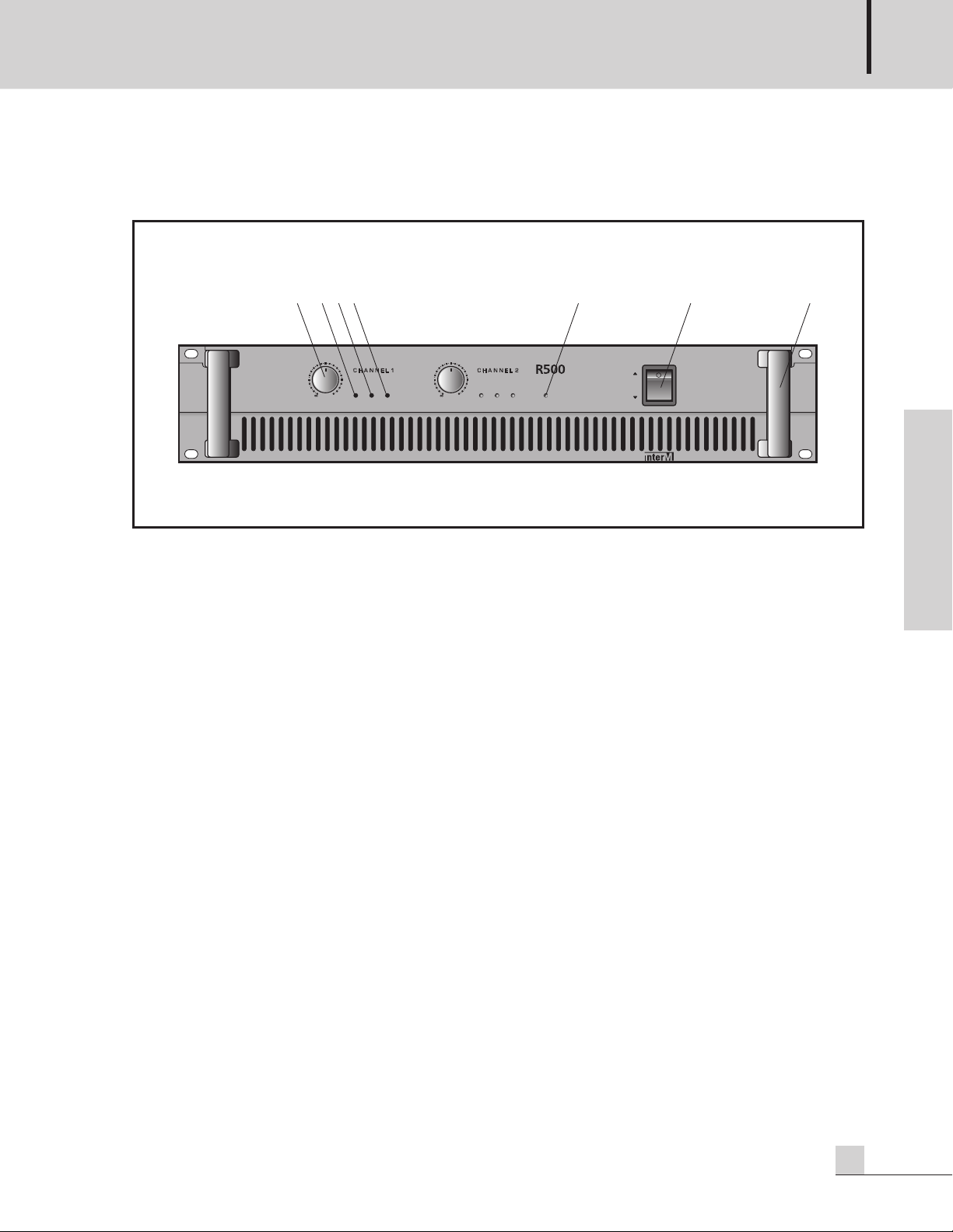
Front Panel
REFERENCE AMPLIFIER
E n g l i s h
1. LEVEL CONTROL
This determines the level of the input signal for each channel. In stereo mode the knobs will determine the signal level
independently for each channel. In the bridge mono mode only the channel 1 level control is used.
2. SIGNAL INDICATOR
This indicates the level of the input signal. This should be illuminated during normal operation.
3. CLIP INDICATOR
This LED warns of a problem in the system when illuminated. Reduce the LEVEL of the device which supplies
signal to the amplifier or reduce the LEVEL control(s) on the amplifier. This LED should not be illuminated
during normal operation.
4. PROTECTION INDICATOR
This LED warns of a problem in the system when illuminated. Reduce the volume and look for problems. It is
possible that the amplifier is too hot or the speaker impedance is too low. This LED should not be illuminated
during normal operation.
5. POWER INDICATOR
This LED indicates the amplifier is switched ON and receiving AC POWER when illuminated.
6. POWER SWITCH
The position of this switch determines whether the power is ON or OFF. The power-on status is confirmed by
the power indicator. Amplifiers are always the last item in a system to be turned on. It is a good idea to turn
down the level controls before applying AC mains power.
7. HANDLE
Handles are provided for moving and installing into equipment enclosures or racks.
R150 PLUS/300 PLUS/500 PLUS
5
Page 8
REFERENCE AMPLIFIER
Rear Panel
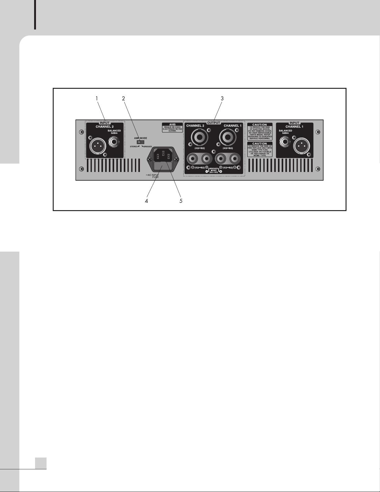
Rear Panel
E n g l i s h
1. BALANCED INPUT CONNECTORS
Each input channel is equipped with a 1/4" TRS and an XLR connector. Standard rules of interconnect apply.
2. MODE SELECTOR SWITCH
Move this switch to select either the STEREO or BRIDGED MONO position as needed for the application.
The Stereo mode is most common. Channel 1 input feeds the channel 1 output. The channel 2 input feeds the
channel 2 output.
The Bridge Mono mode combines both channels to create one larger mono channel. Input signal applied to
channel 1 will be available across the positive terminals of Channel 1 and channel 2. Do not connect the
channel 2 input or any of the negative outputs.
3. OUTPUT CONNECTORS
Binding Posts and Locking speaker connectors are provided. Bridged Mono operation requires a different
method of connecting the cables than Stereo operation. Be sure than the amplifier is in the correct mode
before connecting the speaker load.
4. FUSE
The fuse protects the amplifier by opening the circuit for the AC mains power in case of overload or
malfunction. If the fuse opens, the amplifier (and the various other components in the system) should be checked
for proper operation. If the fuse continues to open after verifying that the system is wired correctly and that an
overload has not occurred, the amplifier should be checked for proper operation by a service technician.
5. AC INPUT
Connect this product to an appropriate AC power source using the supplied Universal AC Power Cord.
6
R150 PLUS/300 PLUS/500 PLUS
Page 9
REFERENCE AMPLIFIER
AUTO BLOWER
PF-9302
M
ANUAL
OFF
A
UTO
POWER LED
Auto Blower(PF-9302)
R150 PLUS/300 PLUS/500 PLUS
R150 PLUS/300 PLUS/500 PLUS
R150 PLUS/300 PLUS/500 PLUS
Blank Panel
Blank Panel
Mounting in a Rack
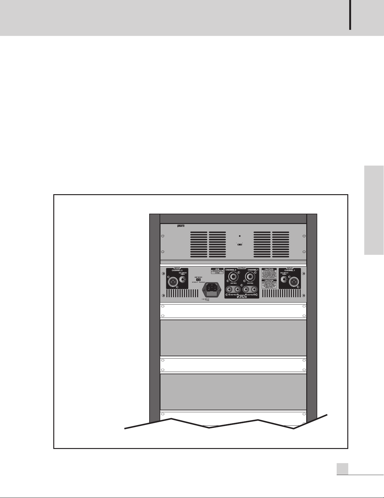
Mounting in a Rack
If multiple high-power amplifiers are mounted in a rack with poor ventilation, the heat from the amplifiers will
cause the interior of the rack (and the amplifiers) to become very hot, which may cause problems with amplifier
performance. If amplifiers are mounted in a rack without an open rear, you should use special care to help
ensure proper ventilation of the rack.
Here are suggestions to help keep the amplifiers properly ventilated:
1. Leave a space of at least 10 cm (4 inches) between the rear door of the rack and the rear panel of the amplifier.
2. Install a fan or blower in the rack to help cool the equipment.
3. Install blank (or vent) panels between amplifiers.
Typical Rack with multiple amplifiers
E n g l i s h
R150 PLUS/300 PLUS/500 PLUS
7
Page 10
REFERENCE AMPLIFIER
Applications-1
Applications-1
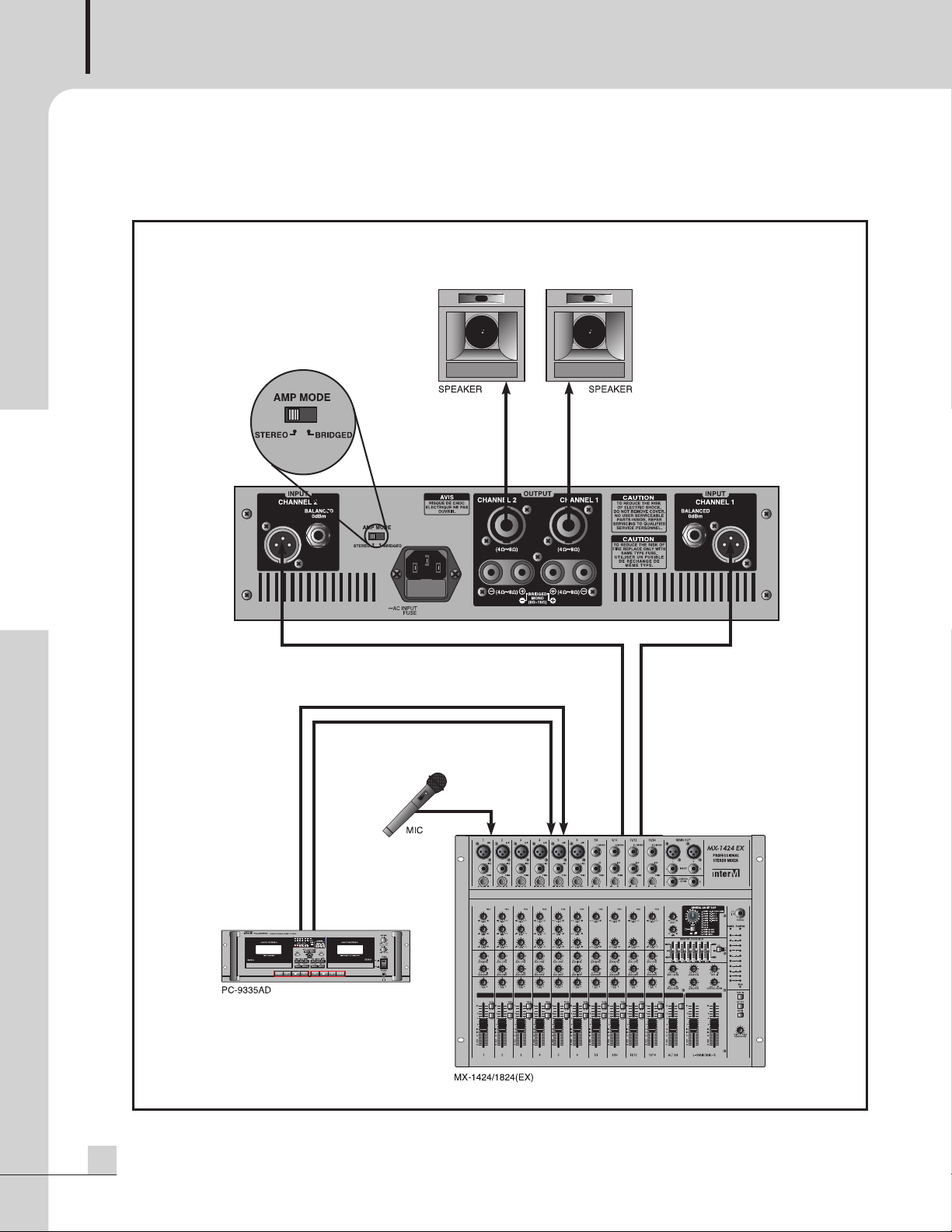
STEREO INSTALLATION
E n g l i s h
8
R150 PLUS/300 PLUS/500 PLUS
Page 11
Applications-2
Applications-2
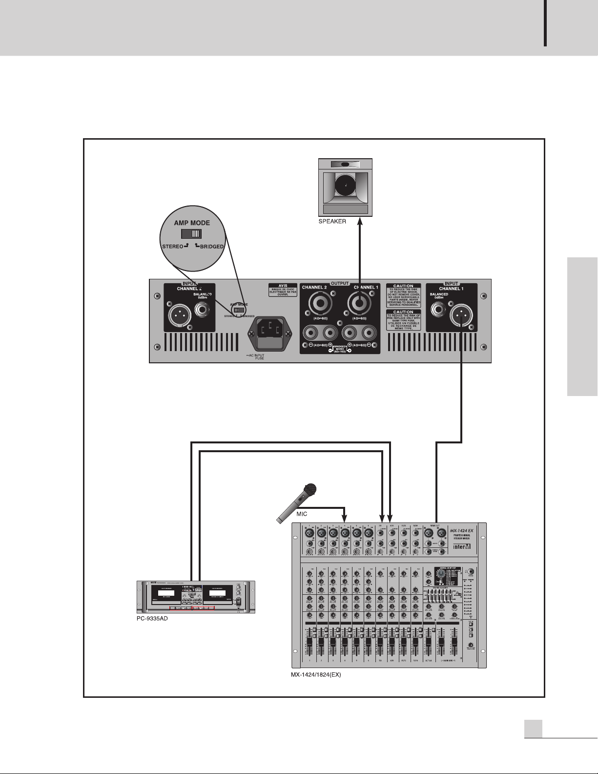
BRIDGED MONO INSTALLATION
REFERENCE AMPLIFIER
E n g l i s h
R150 PLUS/300 PLUS/500 PLUS
9
Page 12

REFERENCE AMPLIFIER
Applications-3
Applications-3
LINKED INSTALLATION
Linking works with stereo or bridged mono operation
E n g l i s h
10
R150 PLUS/300 PLUS/500 PLUS
Page 13

Connections
Ring
Ring
Tip
Tip
Sleeve
Sleeve
Send
Return
Screen
Hot (
positive)
Cold (
negative)
Screen
Left Signal
Right Signal
Ground
Signal
Ground
3 Pole (Stereo) Jack
2 Pole (Mono) Jack
Ring TipSleeve
TipSleeve
2
1
3
Balanced Input
H
ot (positive)
Hot (positive)
Sleeve
Screen
Cold (negative)
Cold (negative)
Connections
Inter-M products are wired to reflect accepted wiring practices used throughout the world.
Balanced XLR connectors are wired as described:
Pin #1 Shield
Pin #2 Positive
Pine #3 Negative
Balanced 1/4" TRS connectors are wired as described:
Tip is Positive
Ring is Negative
Sleeve is Shield
REFERENCE AMPLIFIER
E n g l i s h
Insert Points
Amp/Line Input
Headphones
Unbalanced
Input/Output
AUX Send
R150 PLUS/300 PLUS/500 PLUS
11
Page 14

REFERENCE AMPLIFIER
Locking Speaker Connector
Pin set #1
Wiring Diagram
AMP OUTPUT CH1/CH2
1- 1+
2+ 2-
Negative
Positive
or
CH1 CH2
1- 1+
2+ 2-
BRIDGED MONO
Negative NegativePositivePositive
BRIDGED MONO
NOT CONNECTED
1- 1+
2+ 2-
NOT CONNECTED
OUTPUT
CHANNEL 1CHANNEL 2
(4 ~8 ) (4 ~8 )
(
4 ~8 )
(
4 ~8 )
BRIDGED
M
ONO
(8 ~16 )
Positive
Negative
Positive
Negative
C
H2 CH1
OUTPUT
CHANNEL 1CHANNEL 2
(
4 ~8 )
(
4 ~8 )
(4 ~8 ) (4 ~8 )
BRIDGED
MONO
(8 ~16 )
PositiveNegative
Stereo operation uses one positive and one negative terminal from the same channel.
STEREO CONNECTION
E n g l i s h
Bridged Mono uses the Positive terminals from both channels, the negative terminals have no connection.
Bridged Mono operation has an impedance limitation of 8Ω.
BRIDGED MONO CONNECTION
12
R150 PLUS/300 PLUS/500 PLUS
Page 15

Block Diagram
Block Diagram
REFERENCE AMPLIFIER
E n g l i s h
R150 PLUS/300 PLUS/500 PLUS
13
Page 16

REFERENCE AMPLIFIER
Specifications ........................0dB=0.775 Vrms, Half Power=1/2 Power Output Level (Rated Power)
Specifications
R150 PLUS R300 PLUS R500 PLUS
Power Output Level
STEREO 8Ω(T.H.D 0.5%) 50W 100W 170W
4Ω(T.H.D 0.5%) 75W 150W 250W
BRIDGED MONO 8Ω(T.H.D 0.05%) 150W 300W 460W
8Ω(T.H.D 0.5%) 170W 330W 500W
Frequency Response 20Hz~20kHz(±0.5dB)
T.H.D (20Hz~20kHz, half power) ≤0.1%
Channel Separation (half power 8Ω) ≥70dB
Residual Noise ≤-80dB
Signal to Noise Ratio ≥100dB
E n g l i s h
Input Sensitivity (rated power into 4Ω at 1kHz) 0dBm
Indicators Function Color
Power GREEN
Clip/Limiter RED
Signal GREEN
Protection RED
Protection Power ON/OFF muting, short circuit and thermal
Power Source AC 100V/110V 60Hz, 230V/240V 50Hz
Power Consumption
100V-120VAC Both Channel Driven R
230V-240VAC Both Channel Driven RL=4Ω
Weight 7.2kg/15.9lb 8.4kg/18.5lb 10.4kg/22.
Dimensions 482(W) x 88(H) x 317(D)mm/19(W) x 3.5(H) x 12.5(D)in
(1/8 POWER) 170W 250W 480W
L=4Ω
3A 4.8A 7.8A
1.5A 2.4A 3.9A
* Specifications and design subject to change without notice.
14
R150 PLUS/300 PLUS/500 PLUS
Page 17

REFERENCE AMPLIFIER
Service
Service
Procedures
Take steps to insure the problem is not related to operator error or other products within the system. Information
provided in the troubleshooting portion of this manual may help with this process. Once it is certain that the
problem is related to the product contact your warranty provider as described in the warranty section of this
manual.
Schematic
A Schematic is available by contacting your warranty provider.
Parts List
A Parts List is available by contacting your warranty provider.
Variations and Options
Variations and Options
Variations
Products supplied through legitimate sources are compatible with local AC power requirements.
Options
No optional items are available for this product.
Warranty
Warranty
Warranty terms and conditions vary by country and may not be the same for all products. Terms and conditions
of warranty for a given product may be determined first by locating the appropriate country which the product
was purchased in, then by locating the product type.
E n g l i s h
To obtain specific warranty information and available service locations contact Inter-M directly or the
authorized Inter-M Distributor for your specific country or region.
R150 PLUS/300 PLUS/500 PLUS
15
Page 18

Manual d'Utilisation
Amplificateur Professionnel
R150 PLUS/300 PLUS/500 PLUS
F r e n c h
Page 19

AMPLIFICATEUR PROFESSIONNEL
Sommaire
Sommaire
Felicitations
Précautions ...................................................................................................................................19
Emballage ....................................................................................................................................20
Les Premières Instructions ...............................................................................................................20
Installation
Mise en place ...............................................................................................................................21
Sécurité ........................................................................................................................................21
Description.....................................................................................................................................22
Caractéristiques............................................................................................................................22
Accessoires...................................................................................................................................22
Face Avant.....................................................................................................................................23
Face Arriere...................................................................................................................................24
Montage en Rack .........................................................................................................................25
Applications
Configuration Mode Stéréo ...........................................................................................................26
Configuration Mode Mono/Bridge .................................................................................................27
Configuration Mode «chaînage»....................................................................................................28
Connectique...................................................................................................................................29
F r e n c h
Synoptique ....................................................................................................................................31
Specifications Techniques............................................................................................................32
Maintenance
Procédures....................................................................................................................................33
Schémas.......................................................................................................................................33
Liste des composants......................................................................................................................33
Compatibilites & Options............................................................................................................33
Garantie.........................................................................................................................................33
Page 20

AMPLIFICATEUR PROFESSIONNEL
Felicitations
Felicitations
Un remerciement personnel et des félicitations particulières de la part de la société INTER-M.
Toute l’équipe d’INTER-M se consacre à développer et fabriquer des produits professionnels d’un excellent
rapport qualité/prix et est fière de vous compter parmi ses utilisateurs.
Nous sommes sincèrement persuadés que ce produit vous apportera entière satisfaction car il est le résultat
d’années d’expérience et de savoir-faire au service du domaine de l’Audio professionnel.
Alors, bienvenue dans le monde d’INTER-M et encore tous nos remerciements pour votre contribution à élargir à
travers le monde, la grande famille d’INTER-M.
NSTRUCTIONS RELATIVES AU RISQUE DE FEU, CHOC
I
AVIS
R
ISK OF ELECTRIC SHOCK
DO NOT OPEN.
RISQUE DE CHOC ELECTRIQUE
N
E PAS OUVRIR.
ÉLECTRIQUE, OU BLESSURES AUX PERSONNES.
AFIN DE REDUIRE LES RISQUE DE CHOC ELECTRIQUE, N’ENLEVEZ
AS LE COUVERT (OU LE PANNEAU ARRIERE). NE CONTIENT
P
AUCUNE PIECE REPARABLE PAR L’UTILISATEUR.
CONSULTEZ UN TECHNICIEN QUALIFIE POUR L’ENTRETIENT.
AVIS:
(
%'"%
Il contient des informations qui devraient êtres comprises avant l’opération de votre appareil. Conservez S.V.P. ces instructions pour
consultations ultérieures.
Conservez la boite au cas ou l’appareil devait être retourner pour réparation.
$$$
Lors de l’utilisation de produits électrique, assurez-vous d’adhérer à des précautions de bases incluant celle qui suivent:
$$
L’appareil ne doit être branché qu’à une source d’alimentation correspondant au voltage spécifié dans le manuel ou tel qu’indiqué
sur l’appareil. Cet appareil est équipé d’une prise d’alimentation polarisée. Ne pas utiliser cet appareil avec un cordon de
raccordement à moins qu’il soit possible d’insérer complètement les trois lames. Des précautions doivent êtres prises afin d’eviter
que le système de mise à la terre de l’appareil ne soit désengagé.
#!%
Ne pas placer cet appareil sur un chariot, un support, un trépied ou une table instables. L’appareil pourrait tomber et blesser
quelqu’un ou subir des dommages importants. Utiliser seulement un chariot, un support, un trépied ou une table recommandés par
le fabricant ou vendus avec le produit. Suivre les instructions du fabricant pour installer l’appareil et utiliser les accessoires
recommandés par le fabricant.
Il convient de ne pas placer sur l’appareil de sources de flammes nues, telles que des bougies allumées.
L’appareil ne doit pas être exposé à des égouttements d’eau ou des éclaboussures et qu’aucun objet rempli de liquide tel que des
vases ne doit être placé sur l’appareil. Les dispositifs marqués d’une symbole “d’éclair” sont des parties dangereuses au toucher et
que les câblages extérieurs connectés à ces dispositifs de connection extérieure doivent être effectivés par un opérateur formé ou
en utilisant des cordons déjà préparés.
" )$$
Évitez d’endommager le cordon d’alimentation. )) si le cordon d’alimentation est endommagé.
"&
Consultez un technicien qualifié pour l’entretien de votre appareil.
F r e n c h
R150 PLUS/300 PLUS/500 PLUS
19
Page 21

AMPLIFICATEUR PROFESSIONNEL
Emballage
Nous vous conseillons de prendre un peu de votre temps pour étudier ce manuel afin que vous puissiez vous
familiariser avec l’ensemble des données techniques au sujet de son installation, de ses caractéristiques et de son
mode d’utilisation.
Veillez à le déballer avec précaution pour ne pas l’endommager.
Conservez précautionneusement les composants de l’emballage qui devront-être réutilisés pour un transport
ultérieur (notamment si une ré-expédition chez l’importateur officiel doit s’opérer pour une maintenance ou un SAV).
Les premières instructions
1. Ne pas mettre sous tension votre amplificateur avant l’étape 6. Le commutateur devra être sur la position OFF.
2. Mettre les curseurs rotatifs de volume en face avant à 0, (tournez dans le sens inverse des aiguilles d’une montre
jusqu’à la butée).
3. Câblez une source dotée d’un signal d’entrée approprié soit aux connecteurs XLR symétriques soit aux connecteurs
Jacks 6,35mm symétriques (anneau/masse/pointe) repérés INPUTS.
4. Adaptez le mode désiré à l’aide du sélecteur en face arrière. Le mode stéréo étant le mode le plus utilisé.
5. Câblez les sorties HP (OUTPUTS) vers vos enceintes en prêtant attention au mode (STEREO ou BRIDGE) choisi, voir ci-
dessus, par rapport à l’impédance de vos enceintes.
6. Le commutateur de mise sous tension étant toujours sur OFF, branchez et le reliez le câble secteur à la prise de courant
en vérifiant la conformité électrique.
7. Allumez alors votre amplificateur (commutateur sur la position ON). La LED (témoin lumineux) s’allumera alors.
F r e n c h
8. Votre amplificateur est alors prêt à fonctionner. Augmentez doucement le bouton de volume pour arriver au niveau
sonore souhaité. ATTENTION : Evitez que la LED «PEAK» s’illumine et n’augmentez pas de façon trop importante le
contrôle de volume afin d’éviter d’endommager vos enceintes.
9. D’une façon générale, réglez votre niveau de sorte que la LED «PEAK» ne soit jamais allumée.
20
R150 PLUS/300 PLUS/500 PLUS
Page 22

AMPLIFICATEUR PROFESSIONNEL
S3125A
Installation
Installation
Mise en place
Ne jamais placer votre amplificateur dans un endroit qui pourrait altérer son bon fonctionnement et ses
performances comme : des lieux où la chaleur est excessive (chaleur d’un radiateur, exposition directe au soleil),
humide, poussiéreux, ou encore subissant des vibrations importantes.
Sécurité
1. Lisez attentivement ces instructions.
2. Gardez en lieu sûr ce manuel d’emploi.
3. Prêtez attention aux mises en garde.
4. Suivez rigoureusement toutes les instructions.
5. N’employez pas cet appareil près de l'eau.
6. Nettoyez uniquement votre appareil avec un chiffon sec.
7. Ne bloquez aucune ouverture de ventilation. Installez votre appareil suivant les instructions constructeur.
8. N’installez pas votre appareil à côté d’un radiateur, four, …, exposition directe au soleil, proche de toute source qui
pourrait produire de la chaleur.
9. Ne démontez pas la fiche secteur du câble, ne la remplacez pas, n’inversez pas sa polarité. Ce connecteur est pourvu de
2 lames dont l’une est plus grosse que l’autre. Une prise secteur est composée de ces deux lames et d’un troisième
concernant la masse. Cette dernière représente la mise à la terre donc concerne directement votre sécurité.
Si cette fiche ne paraît pas compatible avec votre installation électrique, consultez un électricien pour remplacer
éventuellement votre prise secteur (prise murale).
10. Protégez votre câble secteur en évitant de marcher dessus, de le coincer ou de l’écraser. Veillez toujours à le brancher
ou à le débrancher par sa fiche et non par le câble en le tirant.
11. Veillez à toujours respecter les consignes constructeur (accessoires/montage).
12. Veillez à toujours respecter l’utilisation des équipements complémentaires recommandés par le constructeur ou le
revendeur. Lorsque vous utiliser un chariot de transport ou fly-case à roulettes, respectez le sens afin d’éviter de
transporter votre amplificateur à l’envers.
13. Débranchez votre appareil lors d’orages ou lors d’une non-utilisation trop importante.
14. Adressez-vous pour toute intervention à un service après-vente qualifié (pannes liées à
l’alimentation secteur, liquide introduit ou objet tombé dans l’appareil qui empêcherait une
utilisation normale).
F r e n c h
S3125A
R150 PLUS/300 PLUS/500 PLUS
21
Page 23

AMPLIFICATEUR PROFESSIONNEL
Description
Description
- R150 PLUS
2 Unités au format RACK 19”.
Amplificateur 2 canaux, développant 150 WATTS sous 8 OHMS (MONO BRIDGE).
- R300 PLUS
2 Unités au format RACK 19”.
Amplificateur 2 canaux, développant 300 WATTS sous 8 OHMS (MONO BRIDGE).
- R500 PLUS
2 Unités au format RACK 19”.
Amplificateur 2 canaux, développant 500 WATTS sous 8 OHMS (MONO BRIDGE).
Caractéristiques
Caractéristiques
- Charge de 4 Ohms stable par canal mode stéréo, charge de 8 Ohms stable par canal mode mono bridgé.
- 2 Unités au format RACK 19”.
- Diodes indicatrices des divers modes de fonctionnement sur la face avant : niveau de signal, crêtes «CLIP», de mise
en protection, et de mise sous tension.
- Equerres de mise en rack pour une installation permanente dans une baie ou un rack au format 19”.
- Câble secteur séparé.
F r e n c h
Accessoire
Un câble secteur séparé est fourni avec cet appareil.
22
R150 PLUS/300 PLUS/500 PLUS
Page 24

Face Avant
POWER
O
FF
ON
POWER
O
FF
ON
LUS
P
NN
POWER
PROTCLIPSIG
19
17
22
13
10
0
1
229
54
1
5
11
12
9
8
7
5
4
3
6
PROTCLIPSIG
19
17
22
13
10
0
1
229
54
1
5
11
12
9
8
7
5
4
3
6
R
EFERENCE AMPLIFIER
5432167
Face Avant
AMPLIFICATEUR PROFESSIONNEL
1. CONTRÔLES DES NIVEAUX DES CANAUX 1 ET 2
Contrôles de niveau du signal d’entrée pour chaque canal. En mode stéréo ou parallèle les potentiomètres
déterminent le niveau de signal indépendamment pour chaque canal. En mode mono «Bridgé» seul le
potentiomètre du canal 1 sera utilisé.
2. DIODES DE NIVEAU
Ces diodes sont allumées lorsque l’amplificateur émet un signal audio en mode de fonctionnement normal.
3. DIODES INDICATRICES DE CRÊTES (CLIP)
Si ces diodes s’allument c’est pour signaler un problème. Réduire le niveau des périphériques qui délivrent un
signal vers l’amplificateur ou réduire le contrôle de niveau sur l’amplificateur. Ces diodes ne doivent pas être
allumées en permanence mais peuvent «flasher» occasionnellement dans des conditions normales d’utilisation.
4. DIODES DE PROTECTION
Si ces diodes s’allument c’est pour signaler un problème sur le système. Réduisez le volume et cherchez la cause
du problème. Il est possible que l’amplificateur soit trop chaud ou que l’impédance des haut-parleurs soit trop
basse. Ces diodes ne doivent pas s’allumer en mode de fonctionnement normal.
5. DIODES DE MODE DE FONCTIONNEMENT
Cette diode indique que l’amplificateur est sous tension (Commutateur sur la position ON).
6. COMMUTATEUR DE MISE EN MARCHE
La position de ce commutateur vous indiquera si votre amplificateur est allumé (ON) ou non (OFF). L’état de
marche est également confirmé par l’état de la diode. L’amplificateur est toujours le dernier élément dans un
système son à mettre en fonction. Il est impératif que les boutons de volume soient totalement au niveau 0
avant extinction ou avant allumage.
F r e n c h
7. POIGNÉES DE MANUTENTION
Vous pouvez déplacer ou installer dans un rack plus facilement votre amplificateur de puissance en utilisant ces
poignées.
R150 PLUS/300 PLUS/500 PLUS
23
Page 25

AMPLIFICATEUR PROFESSIONNEL
Face Arriere
Face Arriere
1. CONNECTEURS D’ENTREE SYMETRIQUE
Chaque canal d’entrée est équipé d’une entrée spéciale qui est compatible soit avec un JACK 6.35mm ou un connecteur XLR.
Les règles de branchement en vigueur s’appliquent bien évidemment à cette «double connexion».
2. SELECTEUR DE MODE
Positionnez le sélecteur en mode STEREO ou MONO BRIDGE en fonction de l’application désirée.
Le mode STEREO est le plus utilisé. L’entrée du canal 1 reçoit le signal qui va être amplifié et dirigé vers la
sortie 1. L’entrée du canal 2 reçoit le signal qui va être amplifié et dirigé vers la sortie 2.
Le mode MONO BRIDGE combine les deux canaux pour créer un seul canal «mono». Le signal entrant sur le
canal 1 ressortira amplifié sur les bornes positives des canaux 1 et 2. Ne rentrez aucun signal dans l’entrée
du canal 2 et ne branchez aucune charge sur les bornes négatives de sortie.
F r e n c h
3. CONNECTEURS DE SORTIE
Les sorties sont sur bornier doublées par des connecteurs SPEAKON. Le branchement des haut-parleurs en
mode BRIDGE MONO est différent du mode STEREO. Assurez vous que le mode sélectionné soit correct vis-àvis de l’impédance des Haut-parleurs.
4. FUSIBLE
Le fusible protège l’amplificateur en «empêchant » le courant AC (secteur) d’alimenter les circuits lors de
surcharges ou de dysfonctionnements liés au courant électrique. Si le filament est rompu, le fusible devra être
changé. La protection électrique a fonctionné. En cas de ruptures répétées (même si les branchements
semblent corrects et qu’aucune surcharge n’a été constatée), il sera nécessaire de faire vérifier votre
amplificateur par un technicien confirmé.
5. CONNEXION SECTEUR
Branchez cet appareil à une prise de courant appropriée en utilisant le câble secteur universel adéquat.
24
R150 PLUS/300 PLUS/500 PLUS
Page 26

AMPLIFICATEUR PROFESSIONNEL
A
UTO BLOWER
PF-9302
M
ANUAL
O
FF
A
UTO
P
OWER LED
Auto Blower(PF-9302)
R150 PLUS/300 PLUS/500 PLUS
R150 PLUS/300 PLUS/500 PLUS
R150 PLUS/300 PLUS/500 PLUS
Blank Panel
Blank Panel
Montage en Rack
Montage en Rack
Si plusieurs amplificateurs doivent-être montés en rack PEU ou PAS DU TOUT ventilé, les radiateurs latéraux de
l’amplificateur ainsi que l’intérieur de l’amplificateur deviendront très chaud et pourront causer certains problèmes au
niveau des performances et de la fiabilité. Si plusieurs amplificateurs sont montés en rack sans ouverture arrière, vous
devrez prêtez attention et vous assurez que le rack soit un minimum ventilé.
Ci-dessous quelques propositions pour garder vos amplificateurs proprement ventilés.
1. Laissez un espace d’au moins 10cm entre la porte arrière d’un rack et le façade arrière de votre amplificateur.
2. Installez un ventilateur ou une Unité de ventilation en haut de votre rack.
3. Installez une plaque de bouchage (de préférence perforée) entre les amplificateurs.
Rack type avec plusieurs unités d’amplificateurs.
F r e n c h
R150 PLUS/300 PLUS/500 PLUS
25
Page 27
AMPLIFICATEUR PROFESSIONNEL
Applications-1
Applications-1
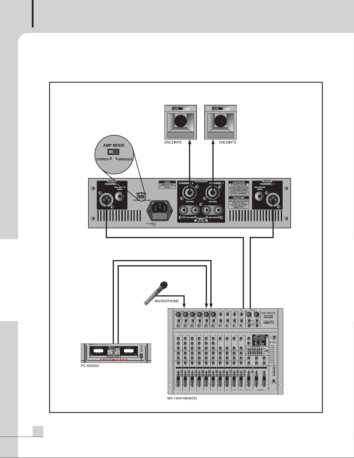
CONFIGURATION MODE STÉRÉO
F r e n c h
26
R150 PLUS/300 PLUS/500 PLUS
Page 28
Applications-2
Applications-2
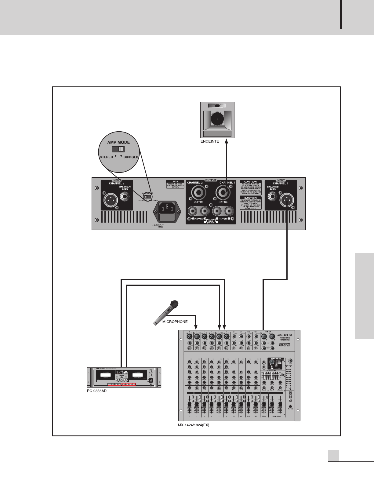
CONFIGURATION MODE MONO/BRIDGE
AMPLIFICATEUR PROFESSIONNEL
F r e n c h
R150 PLUS/300 PLUS/500 PLUS
27
Page 29

AMPLIFICATEUR PROFESSIONNEL
Applications-3
Applications-3
CONFIGURATION MODE «CHAÎNAGE»
Ce cas de figure peut être utilisé soit en mode stéréo ou mono.
F r e n c h
28
R150 PLUS/300 PLUS/500 PLUS
Page 30

AMPLIFICATEUR PROFESSIONNEL
Connectique
Connectique
Les produits INTER-M sont câblés aux normes agréées par les professionnels et suivant les pratiques
généralement utilisées dans le monde entier.
CONNECTEURS SYMETRIQUES TYPE XLR :
Les connecteurs XLR sont configurés comme suit :
- Broche 1 = Ground = Masse
- Broche 2 = Hot (+) = Point Chaud (+)
- Broche 3 = Cold (-) = Point Froid (-)
JACK SYMETRIQUE 6,35mm :
Les connecteurs au format jack 6,35mm sont configurés comme suit :
Pointe= Tip / Hot = Point Chaud (+)
Anneau = Ring / Cold = Point Froid (-)
Tige = Sleeve / Ground = Masse
Câble d’insert
Câble pour entrée niveau ligne
Câble stéréo pour casque
Câble pour entrée/sortie
asymétrique type:
AUX Send
(départ d’auxilliaire/effet)
AUX Return
(retour d’auxilliaire/effet)
F r e n c h
R150 PLUS/300 PLUS/500 PLUS
29
Page 31

AMPLIFICATEUR PROFESSIONNEL
OUTPUT
C
HANNEL 1CHANNEL 2
(4 ~8 ) (4 ~8 )
(4 ~8 ) (4 ~8 )
B
RIDGED
MONO
(8 ~16 )
Mode stéréo utilisant une borne (+) et une borne (-) du même canal.
CONNEXION STÉRÉO
Mode mono utilisant les 2 bornes (+) des 2 canaux. Les bornes négatives (-) ne sont pas utilisées.
ATTENTION : En mode mono l’impédance est limité à 8 Ohms.
CONNEXION MONO BRIDGE
F r e n c h
30
R150 PLUS/300 PLUS/500 PLUS
Page 32

Synoptique
Synoptique
AMPLIFICATEUR PROFESSIONNEL
F r e n c h
R150 PLUS/300 PLUS/500 PLUS
31
Page 33

AMPLIFICATEUR PROFESSIONNEL
Specifications Techniques............0dB=0.775 Vrms, Mi Puissance=1/2 de la puissance (mesurée)
Specifications Techniques
R150 PLUS R300 PLUS R500 PLUS
Puissance RMS
STEREO 8Ω(T.H.D 0.05%) 50W 100W 170W
4Ω(T.H.D 0.05%) 75W 150W 250W
MONO-BRIDGE 8Ω(T.H.D 0.05%) 150W 300W 460W
8Ω(T.H.D 0.5%) 170W 330W 500W
Réponse en Fréquences 20Hz~20kHz(±0.5dB)
Taux de Distortion Harmonique (20Hz~20kHz) ≤0.1%
Séparation de Canal (Puissance/2, 8Ω) ≥70dB
Bruit Résiduel ≤-80dB
Rapport Signal/Bruit ≥100dB
Sensibilité d’Entrée (4Ω à 1kHz) 0dBm
LED (témoins lumineux) Alimentation VERT
Clip/Limiteur ROUGE
Signal VERT
Protection ROUGE
Protection Power ON/OFF (coupé), court-circuit et thermique
Données Électriques AC 100V/110V 60Hz, 230V/240V 50Hz
Consommation Électrique 1.5A 2.4A 3.9A
Poids 7.2kg 8.4kg 10.4kg
Dimensions 482(L) x 88(H) x 317(P)mm
* Caractéristiques pouvant-être modifiées sans préavis.
F r e n c h
32
R150 PLUS/300 PLUS/500 PLUS
Page 34

AMPLIFICATEUR PROFESSIONNEL
Maintenance
Maintenance
Procédures
Reprenez étape par étape afin de vous assurer que le problème ne soit pas lié à l’opérateur (câblage, autre
appareil pouvant causer un dysfonctionnement du système).
Ces informations fournies doivent vous aider à localiser un problème mais en aucun cas vous permettre de
dépanner votre appareil. Si le problème rencontré est un problème purement lié au produit, prenez contact
immédiatement auprès d’un service technique agréé.
Schémas
Un schéma électronique de votre appareil peut-être fourni en vous adressant à votre revendeur.
Liste des composants
Une liste des composants électroniques de votre appareil peut-être fournie en vous adressant auprès de votre
revendeur.
Compatibilites & Options
Compatibilites & Options
Compatibilites
Cet appareil est entièrement compatible et répond aux normes locales en vigueur (CE), normes de sécurité,
normes électriques,…
Options
Aucune option n’est disponible pour cet appareil.
Garantie
Garantie
Les conditions et termes de garantie sont différents et dépendent de chaque pays. Ils ne sont pas soumis par
conséquent aux mêmes règles. Pour obtenir ces informations, vous devez vous adresser à votre revendeur ou
importateur national.
F r e n c h
R150 PLUS/300 PLUS/500 PLUS
33
Page 35

Inter-M, Ltd. (Korea) began operations in 1983.
Since then, Inter-M has grown to become one of the largest manufacturers
of professional audio and commercial sound electronics equipment in the world.
Inter-M has gained worldwide recognition for its own branded products,
as well as private label manufacturing of electronics sold under other names (OEM).
The company is no longer just a Korean company, but rather a global company
that is truly international in scope, with factories and offices in Korea and China,
and sales and marketing operations located in Japan, Europe, and the U.S.A.
With more than 850 employees around the globe,
Inter-M is well-poised for further growth and expansion.
Inter-M Americas, INC.
13875 ARTESIA BLVD. CERRITOS, CA 90703 USA
TEL : +1-562-921-0313, FAX : +1-562-921-0370
Home Page : http://www.inter-m.net, E-mail : info@inter-m.net
Inter-M Corporation
SEOUL OFFICE:653-5 BANGHAK-DONG, DOBONG-KU, SEOUL, KOREA
TEL : +82-2-2289-8140~8, FAX : +82-2-2289-8149
Home Page : http://www.inter-m.com, E-mail : overseas@inter-m.com
October 2011 123235
 Loading...