

Page 1

MADE IN KOREA
August 29, 2012
Page 2

Operation Manual
Audio Matrix Controller
PX-6216
TYPE A European Area
TYPE B America
Page 3

Page 4

Page 5

Page 6

Features
- 16 X 8 AUDIO MATRIXES
Digital audio matrix, 16 inputs x 8 outputs. Computer controlled, this unit is the main component of
the 6000 system 8 bus. (EM, Timer, RM x4, BGM x10).
- PC CONTROL
System Control and configuration is possible via our windows based system software. Remote
operation and connectivity is made possible using the DIB-6000.
-PRIORITY BROADCASTING CONTROL
Connected to the EP-6212, emergency panel, timer and 4 remote microphone (RM-6024) The PX6216 will controls priority broadcastings. Emergency Panel, timer, and remote microphone will have
priority and override of BGM broadcasting.
- REMOTE CONTROL OF PERIPHERALS
The PX-6212 will control source peripherals such as CD, Tuner, and Voice File through the four RS232 terminals.
- VARIOUS BGM INPUTS
1.
1. TYPE A
TYPE A European Area
1. 1.
TYPE ATYPE A
Connection of BGM sources is possible via the 2 XLR combo jack channels, the 6 XLR channels, and 2
RCA jacks.
Condenser microphones with 24V PHANTOM POWER can be connected on channel 1 and 2. These
inputs can select between MIC/Line inputs through setting of operation programs.
2. TYPE B America
Connection of BGM sources is possible via the 8 detachable Euroblock terminals and 2 RCA jacks.
Condenser microphones with 24V PHANTOM POWER can be connected on channel 1 and 2. These
inputs can select between MIC/Line inputs through setting of operation programs
- DSP AUDIO MATRIX
DSP (Digital Signal Processor) controls signal routing, channel mixing, gains, volume, priority and the
5 band EQ..
- FILE AND PRESET-SETTING
System settings are stored in internal memory. Stored file can be restored should setup file of
operation program is deleted or changed. The PX-6216 with the stored file can operate be operated
even if the control PC is offline using memory presets.
European Area
European AreaEuropean Area
Page 7

Front Panel
TYPE A
TYPE B
European Area
America
1. PRESET MEMORY BUTTON AND INDICATOR
6 front panel preset buttons can be programmed and operated even when the control PC
is offline. LED indicators identify the active present.
2. POWER INDICATOR
This LED will be on when Power the PX-6216 is on. It will blink if communication error
with the PC occurs.
Page 8
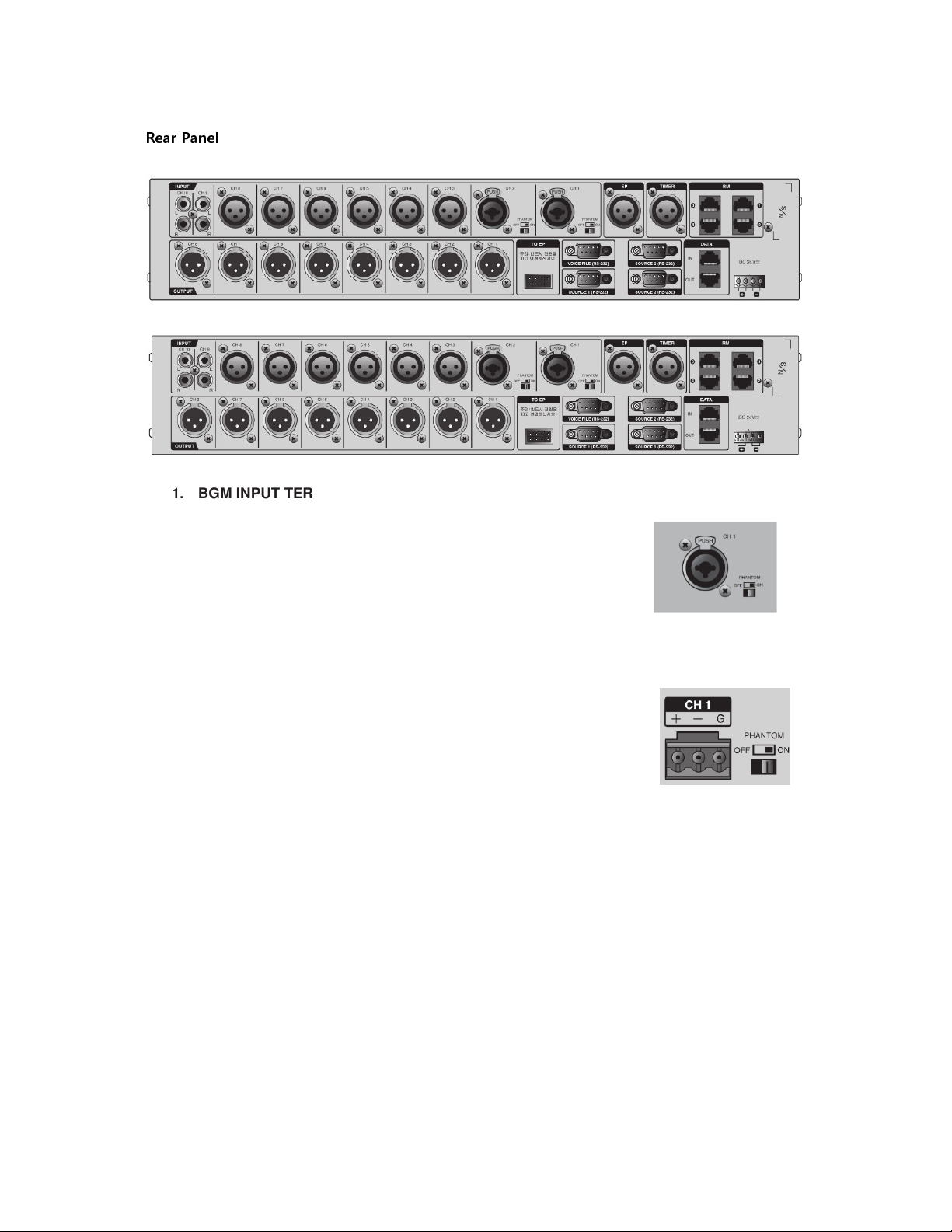
Rear Panel
1. BGM INPUT TERMINAL
TYPE A
TYPE A European Area
TYPE ATYPE A
- INPUT 1 and 2 : Connection of BGM sources is possible via the 2 XLR
combo jack channels. Condenser microphones with 24V PHANTOM POWER
can be connected on channel 1 and 2. These inputs can select between
MIC/Line inputs through setting of operation programs.
- INPUT 3~8 : 6 XLR channels,
- INPUT 9~10 : 2 RCA stereo input jacks.
TYPE B America
INPUT 1 and 2 : Connection of BGM sources is possible via the 2 detachable
Euroblock terminals, Condenser microphones with 24V PHANTOM POWER
can be connected on channel 1 and 2. These inputs can select between
MIC/Line inputs through setting of operation programs
- INPUT 3~8 : BGM sources is possible via the 6 detachable Euroblock
terminals,.
- INPUT 9~10 : 2 RCA stereo input jacks.
2. EMERGENCY AUDIO INPUT TERMINAL
Audio input terminal connecting the emergency panel unit (EP-9216, 9216V, 616, 6216) and allowa
priority broadcast from EP via contact connection terminal.
3. TIMER AUDIO INPUT TERMINAL
Audio input terminal connecting the TIMER (PW-9246,642,6242) allows priority broadcasting via
timer contact triggers.
4. REMOTE MIC COMMUNICATION TERMINAL
This terminal is used to directly connect RM-6024 remote paging microphones.
This port can be expanded to connect up to 8 paging microphones when connected to the RME-6108
Remote microphone extender.
Page 9
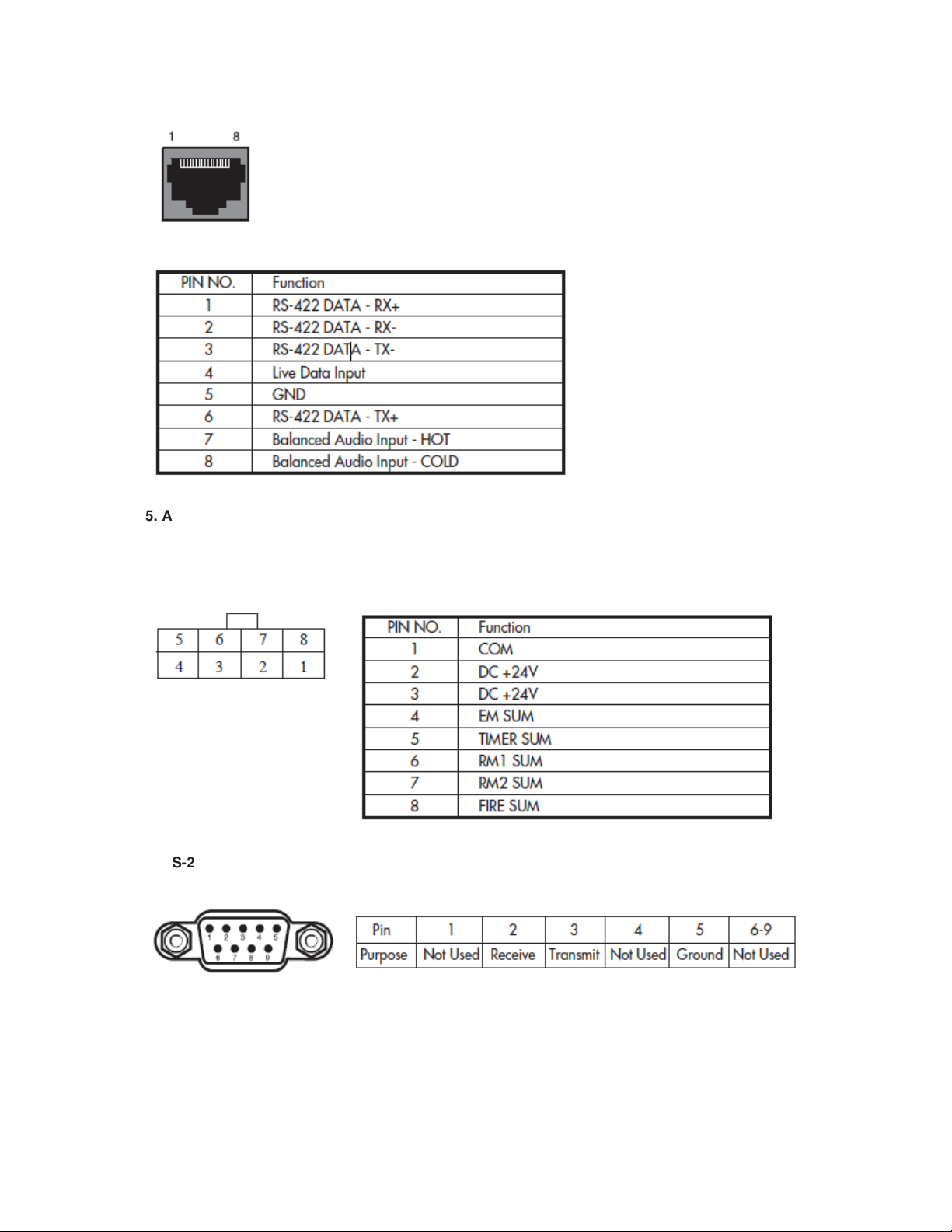
5. AUDIO OUTPUT TERMINAL
8 bus balanced audio output terminal.
6. EMERGENCY PANEL (EP) CONNECTION TERMINAL
This terminal allows for connecting emergency panel unit (EP-9216,9216V,616,6216, etc.) with
priority broadcasting.
7. RS-232 SOURCE UNIT CONTROL TERMINAL
RS-232 communication terminal allows control inter-M source units (CDP, TUNER, VOICE FILE, etc.)
via the PC operation program.
Page 10

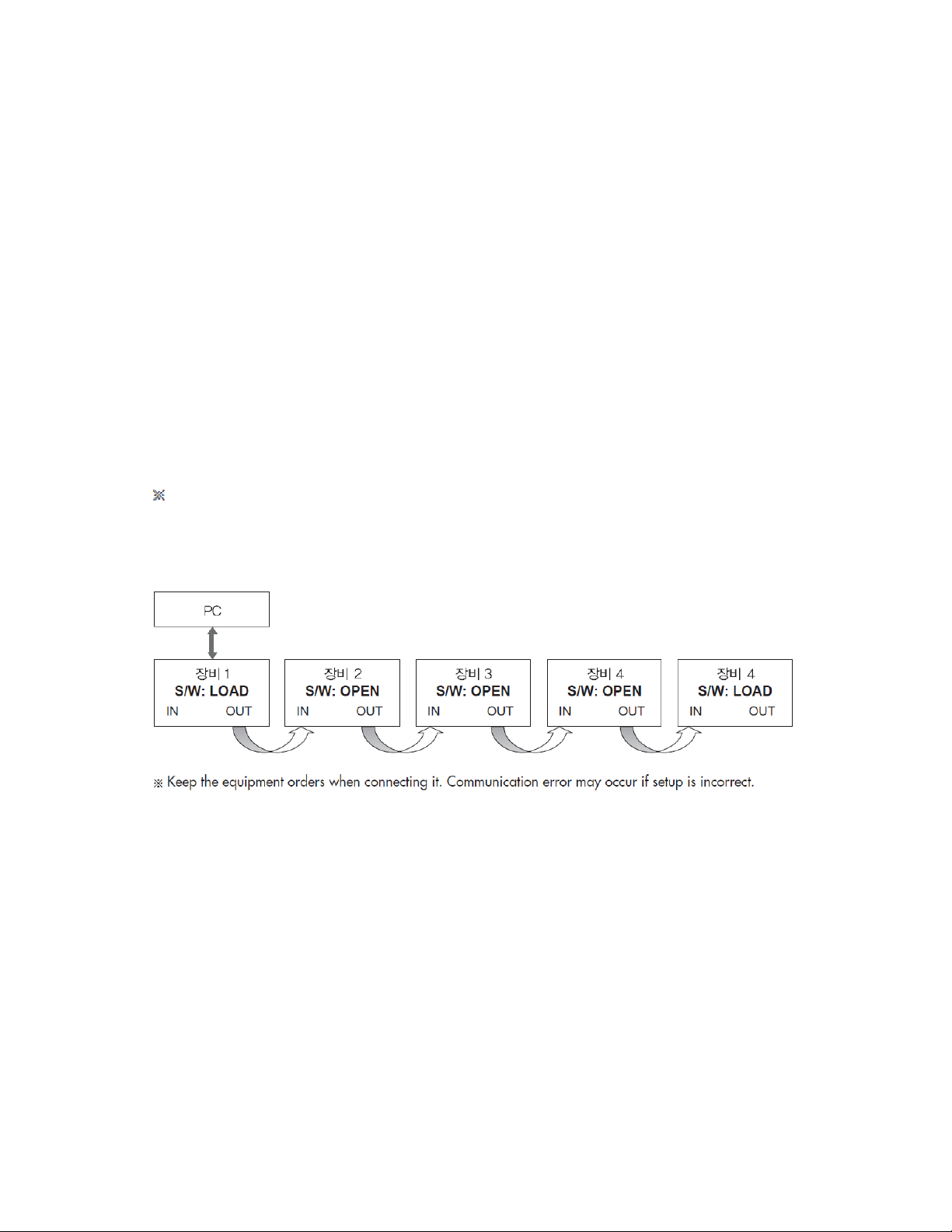
8. DATA LINK IN/OUT TERMINAL
Communication terminal for Windows PC system control.
LINK IN terminal is connected with DIB-6000 and LINK OUT terminal is connected with following
equipment.
9. POWER INPUT TERMINAL
DC Power input terminal. Caution please observe polarity when connecting DC 24V.
Connect to an external power supply or inter-M power distributor. Connect to un-switched power
supply.
Page 11
Equipment Setting and Caution
1. EP CONNECTION
1) When connecting with EP equipment, please connect the matrix terminal of EP and emergency
panel connection terminal by using the EP connector supplied as an accessory of the PX-6216.
2) Connect the audio signal of PRE OUT of EP to EP audio input terminal on the top of PX-6216.
Volume control of EP input can be set in the equipment setting of operation program.
2. TIMER CONNECTION
1) When connecting with TIMER, connect the Timer contact point input terminal of ECS-6216MS and
remote output terminal of Timer.
2) Connect the audio signal of channel out terminal of Timer to the Timer audio input terminal on the
top of PX-6216. Volume control of Timer input can be set in the equipment setting of operation
program.
3. DATA LINK IN/OUT CONNECTION
1) Connect the LINK IN terminal of PX-6216 and LINK OUT terminal of DIB-6000 with UTP cable
wired strait or direct method. Connect the DIB-6000 to PC by using USB cable.
2) Set the termination switch terminal of DIB-6000 to LOAD.
Communication error may occur if setup is incorrect.
3) Connect the other equipment including ECS-6216MS to each other through LINK IN/OUT terminal.
4) Set the TERMINATION switch of the last equipment in the data link to LOAD. Set the other
equipment to OPEN.
Page 12

Block Diagram
Page 13

Page 14

TYPE A
European Area
Page 15

Block Diagram
TYPE B
America
Page 16

Specifications
PX-6216
Rated Output 0dBV (Balanced)
EM, TIMER, RM
Input Sensitivity
Frequency Response
Total Harmonic Distortion
Signal to Noise Ratio
(A-weight Filter)
Maximum S/N LINE Better than 100Db (+8dBV Input)
Phantom MIC Power BGM 1,2 DC 24V
Priority
Communication Interface
Standard
Operation Temperature
BGM 1~8 LINE
BGM 1~8 MIC
BGM 9,10 LINE
±
3dB
LINE Less than 0.01%
MIC Less than 0.1%
LINE Better than 85dB
MIC Better than 60dB
EM
LINK IN/OUT RS-485 (Max. Distance 1km)
RM RS-422 (Max. Distance 1km)
SOURCE RS-232 (Max. Distance 12m)
-10dBV/20kΩ (Balanced)
-10dBV/3k
-50dBV/3k
-10dBV/20k
>TIMER>RM1>RM2>RM3>RM4>BGM
Ω (Balanced)
Ω (Balanced)
Ω (Unbalanced)
20Hz~20kHz
-10
℃~+40℃
Power Source DC24V, 1A
Weight(SET) 4.3kg
Dimensions(SET)
*
Specifications and design are subject to change without notice.
Page 17

※ DIMENSIONS
TYPE A European Area
Page 18

※ DIMENSIONS
TYPE B America
Page 19

Service
Procedures
Take steps to insure the problem is not related to operator error or other products within the system.
Information provided in the troubleshooting portion of this manual may help with this process. Once it
is certain that the problem is related to the product contact your warranty provider as described in the
warranty section of this manual.
Schematic
A Schematic is available by contacting your warranty provider.
Parts List
A Parts List is available by contacting your warranty provider.
Variations and options
Variations
Variations of this product exist to reflect the variations in AC power requirements throughout the world.
Product supplied through local sources is compatible with local AC power requirements.
Options
No optional items are available for this product.
Warranty
Warranty terms and conditions vary by country and may not be the same for all products. Terms and
conditions of warranty for a given product may be determined first by locating the appropriate country
which the product was purchased in, then by locating the product type.
To obtain specific warranty information and available service locations contact Inter-M directly or the
authorized Inter-M Distributor for your specific country or region.
 Loading...