

Page 1
Operation Manual
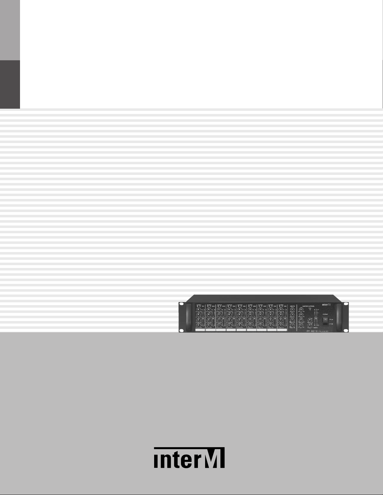
Audio Pre Amplifier
PP-6213
* Rack mount products in the Western Hemisphere(North America, South America,
and the Caribbean) do not have handles installed due to customer preference.
Page 2
AUDIO PRE AMPLIFIER
Welcome
Welcome
A personal welcome to you from the management and employees of Inter-M
All of the co-workers here at Inter-M are dedicated to providing excellent products with inherently good value,
and we are delighted you have purchased one of our products.
We sincerely trust this product will provide years of satisfactory service, but if anything is not to your complete
satisfaction, we will endeavor to make things right.
Welcome to Inter-M, and thank you for becoming part of our worldwide extended family!
This symbol is intend ed to aler t the user to the
CAutION
RISK OF ELECTRIC SHOCK
DO NOT OPEN
CAUTION: TO REDUCE THE RISK OF ELECTRIC SHOCK.
DO NOT REMOVE COVER (OR BACK).
NO USER-SERVICEABLE PARTS INSIDE.
REFER SERVICING TO QUALIFIED SERVICE PERSONNEL.
Caution: To prevent electric shock do not use this (polarized) plug with
Attentions: Pour prévenir les chocs électriques ne pas utiliser cette
WARNING
To prevent fire or shock hazard, do not
expose the unit to rain or moisture.
*WARNING FOR YOUR PROTECTION PLEASE READ THE FOLLOWING-WATER AND MOISTURE: Unit should not be used near water(e.g.
near a bathtub, washbowl, kitchen sink, laundry tub, in a wet basement, or near a swimming pool, etc). Care should be taken so than objects do
not fall and liquids are not spilled into the enclosure through openings.
*CLASS 2 WIRING (Adjacent to speaker terminal): The speaker output of this apparatus can exceed 10 Watts and could be a shock injury.
Connection to speakers should be performed by a skilled person.
*Do not install this equipment in a confined space such as a book case or similar unit.
*This apparatus shall not be exposed to dripping or splashing and no objects filled with liquids, such vases, shall be placed on the apparatus.
*This apparatus shall be connected to a mains socket outlet with a protective earthing connection.
It has heed to be easy to disconnect the device. To disconnect the device from power, separate AC input cable from inlet or unplug the AC Cord.
*
*
The socket-outlet shall be installed near the equipment and shall be easily accessible.
CAutION
*These servicing instructions are for use by qualified service personnel only. To reduce the risk of electric shock, do not perform any servicing
other than that contained in the operating instructions unless you are qualified to do so.
NOtE
*This equipment has been tested and found to comply with the limits for a Class A digital device, pursuant to Part 15 of the FCC Rules. These limits are
designed to provide reasonable protection against harmful interference when the equipment is operated in a commercial environment. This equipment
generates, uses, and can radiate radio frequency energy and, if not installed and used in accordance with the instruction manual, may cause harmful
interference to radio communications. Operation of this equipment in a residential area is likely to cause harmful interference in which case the user will
be required to correct the interference at his own expense.
presence of uninsulated “dangerous voltage” within
the prod uct’s enclos ure t hat m ay be of suffi cient
magnitude to constitute a risk of electric shock to
persons.
This symbol is intend ed to aler t the user to the
presence of important operation and maintenance
(servicing) instructions in the literature accompanying
the appliance.
an extension cord, receptacle or other outlet unless the blades
can be fully inserted to prevent blade exposure.
fiche polarisée avec un prolongateur, une prise de courant
on une autre sortie de courant, sauf si les lames peuvent
étre insérées à fon d sa ns en laisser auc une par tie à
découvert.
Page 3

AUDIO PRE AMPLIFIER
Contents
Contents
Unpacking .......................................................................................................................................2
Installation
Environment....................................................................................................................................2
Important Safety Instructions.............................................................................................................2
Features............................................................................................................................................3
Operation ........................................................................................................................................3
Front Panel ......................................................................................................................................4
Rear Panel .......................................................................................................................................6
Applications ....................................................................................................................................8
Block Diagram ................................................................................................................................9
Specifications ................................................................................................................................10
Service
Procedures....................................................................................................................................12
Schematic.....................................................................................................................................12
Parts List .......................................................................................................................................12
Variations and Options ...............................................................................................................12
Warranty .......................................................................................................................................12
PP-6213
1
Page 4

AUDIO PRE AMPLIFIER
S3125A
Unpacking
Unpacking
Although your PP-6213 is neither complicated nor difficult to operate, we recommend you take a few minutes to
read this brief manual and familiarize yourself with the important information regarding product features, setup
and operation.
As with most electronic devices, we strongly recommend you retain the original packaging. In the unlikely event
the product must be returned for servicing, the original packaging (or reasonable equivalent) is required.
Installation
Installation
Environment
Never place this product in an environment which could alter its performance or reduce its service life. Such
environments usually include high levels of heat, dust, moisture, and vibration.
IMPORTANT SAFETY INSTRUCTIONS
1. Read these instructions.
2. Keep these instructions.
3. Heed all warnings.
4. Follow all instructions.
5. Do not use this apparatus near water.
6. Clean only with dry cloth.
7. Do not block any ventilation openings. Install in accordance with the manufacturer’s instructions.
8. Do not install near any heat sources such as radiators, heat registers, stoves, or other apparatus (including
amplifiers) that produce heat.
9. Do not defeat the safety purpose of the polarized or grounding-type plug. A polarized plug has two blades
with one wider than the other. A grounding type plug has two blades and a third grounding prong. The wide
blade or the third prong are provided for your safety. If the provided plug does not fit into your outlet, consult
an electrician for replacement of the obsolete outlet.
10. Protect the power cord from being walked on or pinched particularly at plugs, convenience receptacles, and
the point where they exit from the apparatus.
11. Only use attachments/accessories specified by the manufacturer.
12. Use only with the cart, stand, tripod, bracket, or table specified by the manufacturer, or sold with the apparatus.
When a cart is used, use caution when moving the cart/apparatus combination to avoid injury from tip-over.
13. Unplug this apparatus during lightning storms or when unused for long periods of time.
14. Refer all servicing to qualified service personnel. Servicing is required when the
apparatus has been damaged in any way, such as power-supply cord or plug is
damaged, liquid has been spilled or objects have fallen into the apparatus, the
apparatus has been exposed to rain or moisture, does not operate normally, or has
been dropped.
S3125A
2
PP-6213
Page 5

AUDIO PRE AMPLIFIER
Features
FeaturesFeatures
- 9 CHANNEL INPUT, 1 CHANNEL FOR MASTER OUTPUT, 2 CHANNEL FOR SUB OUTPUT, 1 CHANNEL FOR
RECORDING OUTPUT
9 channel input and 1 channel for master output and 2 sub channel for flexible use and 1 channel for recording
output which is not affected by the master level fader built in.
- AUXILIARY INPUT AND PRIORITY INPUT
Auxiliary Input is built in so that users can use the external sound source in there convenience and the sound
source connected to 2 channels of this priority input is played prior to the other input.
- EQ ON EACH CHANNEL
3 band (High, Mid, Low) Graphic equalizers are built-in so that a user can adjust the tone of sound to there taste.
- PHANTOM POWER
Phantom powers are available on channel 1 and 2 for the condenser microphone.
- DUCKING
Ducking function available on channel 1 and 2 enable their sound source to be broadcast prior to the others. A
user can select whether to use it or not.
Operation
Operation
1. Plug into the outlet directly or connect DC terminal in right polarity with the DC power supplier.
2. Locate all knobs for sound quality at “0” and minimize all knobs for sound level.
3. When power switch is on, it starts to work.
4. Please adjust the gain of the input signal with trim control according to the signal level of the input channel
connected with CD player or deck or microphone.
5. When using level controller of the input channel, make favorable audio mixing and adjust the output level with
level controller of the master output.
6. When monitoring output level, adjust favorable color of tone using input channel tone controller and master
channel tone controller.
PP-6213
3
Page 6

AUDIO PRE AMPLIFIER
TRIM
-
60-16
HI
M
ID
LOW
-12 +12
-12 +12
-
12 +12
SIGP
EAK
CH1
M
ID
+12-
12
LOW
+12
+12
HI
-12
-12
-60-
16
TRIM
P
EAKSIG
CH2 CH3
M
ID
+
12
LOW
-
12
+12
+12
-12
-12
HI
-
60
TRIM
-
16
P
EAKSIG
CH4
M
ID
+
12
LOW
-
12
+12
+12
-12
-12
HI
-
60
TRIM
-
16
P
EAKSIG
CH5
M
ID
+
12
LOW
-
12
+12
+12
-12
-12
HI
-
60
TRIM
-
16
P
EAKSIG
CH6
M
ID
+
12
LOW
-
12
+12
+12
-12
-12
HI
-
60
TRIM
-
16
P
EAKSIG
CH7
M
ID
+
12
LOW
-
12
+12
+12
-12
-12
HI
-
60
TRIM
-
16
P
EAKSIG
CH8
M
ID
+
12
LOW
-
12
+12
+12
-12
-12
HI
-
60
TRIM
-
16
P
EAKSIG
CH9
M
ID
+
12
LOW
-
12
+12
+12
-12
-12
HI
-
60
TRIM
-
16
P
EAKSIG
P
RIORITY1
PRIORITY2
AUX2
AUX1 HI
HI-MID
LOW
L
OW-MID
-
12
-12
-12
+
12
+12
+12
SUB2
S
UB1
PEAK
MASTER OUTPUTS
MASTER
INPUTS
+
12-12
6
0
0
6
0
0
0
0
0
10
O
FF
ON
POWER
12 34 5 6 7
8 9 10 11 12
Front Panel
Front Panel
1. TRIM CONTROLS 1~9
These knobs provide continuous control of pre-amp gain from +14dB to +58dB.
2. SIGNAL INDICATORS 1~9
These LED indicator light when signal source come in.
3. PEAK INDICATORS 1~9
These LED indicators light when the input signal to the associated channel is 3dB below clipping. If the
indicator is lit steadily, reduce the channel’s Trim level (1) to avoid distortion.
4. CHANNEL FADERS 1~9
These are the main output level controls for each channel. They provide continuous control of the signal level
sent from the associated input channel to the master output buss. Faders of unused channels should be set to
fully anticlockwise.
5. AUX INPUT LEVELS (AUX1, AUX2)
These knobs provide continuous control of the levels for signals connected to the rear-panel Aux 1 and Aux 2 inputs.
6. MASTER PEAK INDICATOR
These LED indicators light when the master output signal is 3dB below clipping. If the indicator is lit steadily,
reduce the master output level (7), or the levels from the active input channels (4) to avoid distortion.
7. MASTER OUTPUT CONTROL
This is the controller that adjusts the level of the master output which is a mixture of each channel’s signal.
PP-6213
4
Page 7

AUDIO PRE AMPLIFIER
8. CHANNEL EQ CONTROLS (3 BAND)
hese knobs provide continuous control of equalization up to 12dB boost and cut. Three bands of
T
equalization are:
Low : 100Hz, Mid : 1kHz, High : 10kHz
9. PRIORITY CONTROLS (PRIORITY 1, PRIORITY 2)
This is the volume controller for the priority input.
When the terminal for the priority is connected to PE-6103(Chime & Siren), locating this controller at more
than 12 o’clock direction is recommended.
- First place : Priority input 1, input 2
- Second place : When ducking is on, channel 1, channel 2
- Third place : other channels (channel 3 to 9)
10. MASTER EQ CONTROLS (4 BAND EQUALIZER)
These knobs provide continuous control of equalization up to 12dB boost and cut. Four bands of equalization
are:
Low : 80Hz, Low-Mid : 400Hz, Hi-Mid : 2kHz, High : 10kHz
11. SUB OUTPUT CONTROLS (SUB1, 2)
Level controller for Sub1 and 2 outputs.
12. POWER SWITCH
Press this switch to turn the unit on, as indicated by the Power LED in the switch. Pressing it again to turn the
unit off.
PP-6213
5
Page 8

AUDIO PRE AMPLIFIER
S
N
w
ww.inter-m.com
DUCK P.PWR
CH1CH2
DUCK P.PWR
CH3CH4CH5CH6CH7CH8CH9
LINE IN
MIC IN
L
RR
L
R
L
2
1
AUX
1
2
PRIORITY
+-
DC INPUT
24V
INSERTREC OUT
MASTER
2
1
SUB OUTOUTPUT
INPUTINPUT
LINE IN
MIC IN
LINE IN
MIC IN
LINE IN
MIC IN
LINE IN
MIC IN
LINE IN
MIC IN
LINE IN
MIC IN
LINE IN
MIC IN
LINE IN
MIC IN
1 2 3 4 5
6 7 8 9 10 11 12 13
1 2 7 3 4 5 12 13
6 8 9 11 10
Rear Panel
Rear Panel
<Type A>
<Type B>
1. MASTER OUTPUT
This is a balanced XLR output jack for connecting to the input of a power amp.
(Output level : +4dBm/600Ω)
2. SUB OUTPUTS 1-2
These are unbalanced 1/4? phone jack outputs for connecting the input of a power amp or other audio
input. (Output level : +4dBm/600Ω)
3. PRIORITY INPUTS 1-2
These are line level inputs on unbalanced 1/4? phone jacks. When the signal is present at these inputs, all
other inputs are muted. The level for these inputs is controlled by the front-panel priority level control (9).
4. AUX INPUTS 1-2
6
PP-6213
These are line level inputs on unbalanced 1/4? phone jacks. Their level is controlled by the front panel AUX
level controls (5). (Input level : -10dBm/20kΩ)
Page 9

AUDIO PRE AMPLIFIER
5. MIC INPUTS 1-9
hese are mic-level inputs on balanced three-pin XLR connectors. (1:GND, 2:HOT, 3:COLD)
T
Their level is controlled by the front panel Trim controls (1). Phantom power is supplied to these inputs with
the rear-panel phantom power(+18V) switch (13).
6. AC CONNECTOR AND FUSE HOLDER
Connect the supplied standard AC input cable to this input. The fuse holder below the input contains the AC
overload protection fuse. If the fuse has blown out, replace it with a fuse of the same type and rating. If the
fuse continues to blow, refer servicing to a qualified service technician.
7. REC OUTPUT
This is the unbalanced output for recording mixed signals the output level is -10dBm/10kΩ.
8. INSERT
This is an unbalanced line-level input and output jack, provided for connecting external devices to the mixer’s
outputs. ‘Tip(S)’ for signal output and ‘Ring(R)’ for input.
9. DC INPUT TERMINALS
These terminals are provided for the connection of 24V DC power source, such as the Inter-M PD-6359.
Connect a 24V DC battery source to these terminals.
10. STEREO LINE INPUTS 7-9
These are provided as three sets of stereo inputs, for the connection of consumer level input sources.
11. MONO LINE INPUTS 1-6
These are line-level inputs on balanced connectors. These are provided as six mono inputs, for the connection
of line-level input sources.
12. PRIORITY SWITCHES
When the priority switches are activated, signals of the associated Mic Inputs 1 and 2 will automatically
lower the gain level of the other input channels.
13. PHANTOM POWER SWITCHES
Pressing these switches activates the +18VDC phantom power supply to associated Mic Inputs 1 and 2, for
use with condenser mics requiring external power. Push this switch again to turn off the phantom power.
? NOTE : In case the switch is on without the lowest level of input channel and master output, high voltage
may occur by assigning DC +18V suddenly to the mic input which can harm the speakers.
PP-6213
7
Page 10

AUDIO PRE AMPLIFIER
DUCK P.PWR
CH1CH2
DUCK P.PWR
CH3CH4CH5CH6CH7CH8CH9
LINE IN
MIC IN
L
RR
L
R
L
2
1
AUX
1
2
PRIORITY
+-
D
C INPUT
24V
INSERTREC OUT
MASTER
2
1
SUB OUTOUTPUT
INPUTINPUT
LINE IN
MIC IN
LINE IN
MIC IN
LINE IN
MIC IN
LINE IN
MIC IN
LINE IN
MIC IN
LINE IN
MIC IN
LINE IN
MIC IN
LINE IN
MIC IN
S
N
www.inter-m.com
MICROPHONE
CASSETTE DECK
CD PLAYER
TUNER
KEY BOARD
DISTRIBUTOR
POWER AMPLIFIER
EMERGENCY PANEL
SPEAKERS
MICROPHONE
Applications
Applications
8
PP-6213
Page 11

Block Diagram
Block Diagram
AUDIO PRE AMPLIFIER
PP-6213
9
Page 12

AUDIO PRE AMPLIFIER
Specifications
Specifications
PP-6213
Master Output +4dBm/600Ω, BAL
Rated Output (1kHz) SUB 1,2 Output +4dBm/600Ω, UNBAL
REC Output -10dBm/10kΩ, UNBAL
MIC (CH1~CH9) -60dBm/600Ω, BAL
LINE (CH1~CH6) -20dBm/47kΩ, BAL
Input Sensitivity
/Impedance
T.H.D Less than 0.3%
Frequency Response 30Hz-20kHz (+1dB, -3dB)
Input Channel
Equalizer
Output Channel
Equalizer
Residual Noise (at V/R Min) Less than -90dB
Crosstalk Less than -60dB
LINE (CH7~CH9) -20dBm/47kΩ, UNBAL
AUX 1,2 -10dBm/20kΩ, UNBAL
Priority 1,2 0dBm/20kΩ, UNBAL
Insert 0dBm/20kΩ, UNBAL
HIGH ±12dB (10kHz)
MID ±12dB (1kHz)
LOW ±12dB (100HZ)
HIGH ±12dB (10kHz)
HI-MID ±12dB (2kHz)
LOW-MID ±12dB (400Hz)
LOW ±12dB (80Hz)
Phantom Power +18V DC
Operation Temperature -10°C ~ +40°C/14°F~104°F
Power Source
Power Consumption 10W
Weight (SET) 4.8kg/10.6lb
Dimensions (SET) 482(W)x88(H)x280(D)mm/19(W)x3.5(H)x11(D)in
* Specifications and design are subject to change without notice.
10
PP-6213
(Supplied AC mains transformer depends on country requirements)
100–120VAC or 220–240VAC; 50/60Hz
Page 13

4
40
482
28088
※ DIMENSIONS
AUDIO PRE AMPLIFIER
PP-6213
11
Page 14

AUDIO PRE AMPLIFIER
Service
Service
Procedures
Take steps to insure the problem is not related to operator error or other products within the system. Information
provided in the troubleshooting portion of this manual may help with this process. Once it is certain that the
problem is related to the product contact your warranty provider as described in the warranty section of this
manual.
Schematic
A Schematic is available by contacting your warranty provider.
Parts List
A Parts List is available by contacting your warranty provider.
Variations and Options
Variations and Options
Variations
Variations of this product exist to reflect the variations in AC power requirements throughout the world. Product
supplied through local sources are compatible with local AC power requirements.
Options
No optional items are available for this product.
Warranty
Warranty
Warranty terms and conditions vary by country and may not be the same for all products. Terms and conditions
of warranty for a given product may be determined first by locating the appropriate country which the product
was purchased in, then by locating the product type.
To obtain specific warranty information and available service locations contact Inter-M directly or the
authorized Inter-M Distributor for your specific country or region.
12
PP-6213
Page 15

Inter-M, Ltd. (Korea) began operations in 1983.
Since then, Inter-M has grown to become one of the largest manufacturers
of professional audio and commercial sound electronics equipment in the world.
Inter-M has gained worldwide recognition for its own branded products,
as well as private label manufacturing of electronics sold under other names (OEM).
The company is no longer just a Korean company, but rather a global company
that is truly international in scope, with factories and offices in Korea and China,
and sales and marketing operations located in Japan, Europe, and the U.S.A.
With more than 850 employees around the globe,
Inter-M is well-poised for further growth and expansion.
Inter-M Americas, Inc.
13875 Artesia Blvd. Cerritos, CA 90703 USA
TEL : +1-562-921-0313, FAX : +1-562-921-0370
Home Page : http://www.inter-m.net, E-mail : info@inter-m.net
Inter-M Corporation
Seoul OFFICE:653-5 BANGHAK-DONG, DOBONG-KU, SEOUL, KOREA
TEL : +82-2-2289-8140~8, FAX : +82-2-2289-8149
Home Page : http://www.inter-m.com, E-mail : overseas@inter-m.com
MADE IN KOREA
June 2012 130443
 Loading...