

Page 1
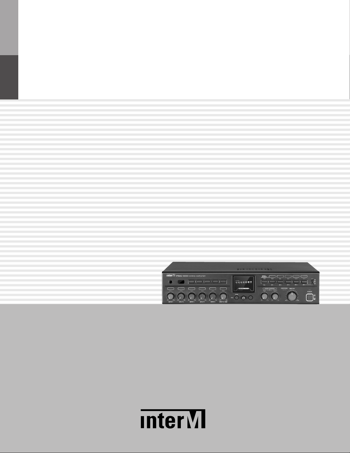
Operation Manual
Mixing Amplifier
PMU-360/480/600
Page 2
MIXING AMPLIFIER
Welcome
Welcome
A personal welcome to you from the management and employees of Inter-M
All of the co-workers here at Inter-M are dedicated to providing excellent products with inherently good value,
and we are delighted you have purchased one of our products.
We sincerely trust this product will provide years of satisfactory service, but if anything is not to your complete
satisfaction, we will endeavor to make things right.
Welcome to Inter-M, and thank you for becoming part of our worldwide extended family!
This s ym bol is intende d to a lert the user to t he
CAutION
RISK OF ELECTRIC SHOCK
DO NOT OPEN
CAUTION: TO REDUCE THE RISK OF ELECTRIC SHOCK.
DO NOT REMOVE COVER (OR BACK).
NO USER-SERVICEABLE PARTS INSIDE.
REFER SERVICING TO QUALIFIED SERVICE PERSONNEL.
Caution: To prevent electric shock do not use this (polarized) plug with
Attentions: Pour prévenir les chocs électriques ne pas utiliser cette
WARNING
To prevent fire or shock hazard, do not
expose the unit to rain or moisture.
*WARNING FOR YOUR PROTECTION PLEASE READ THE FOLLOWING-WATER AND MOISTURE: Unit should not be used near water(e.g.
near a bathtub, washbowl, kitchen sink, laundry tub, in a wet basement, or near a swimming pool, etc). Care should be taken so than objects do
not fall and liquids are not spilled into the enclosure through openings.
*CLASS 2 WIRING (Adjacent to speaker terminal): The speaker output of this apparatus can exceed 10 Watts and could be a shock injury.
Connection to speakers should be performed by a skilled person.
*Do not install this equipment in a confined space such as a book case or similar unit.
*This apparatus shall not be exposed to dripping or splashing and no objects filled with liquids, such vases, shall be placed on the apparatus.
*This apparatus shall be connected to a mains socket outlet with a protective earthing connection.
It has heed to be easy to disconnect the device. To disconnect the device from power, separate AC input cable from inlet or unplug the AC Cord.
*
CAutION
*These servicing instructions are for use by qualified service personnel only. To reduce the risk of electric shock, do not perform any servicing
other than that contained in the operating instructions unless you are qualified to do so.
NOtE
*This equipment has been tested and found to comply with the limits for a Class A digital device, pursuant to Part 15 of the FCC Rules. These limits are
designed to provide reasonable protection against harmful interference when the equipment is operated in a commercial environment. This equipment
generates, uses, and can radiate radio frequency energy and, if not installed and used in accordance with the instruction manual, may cause harmful
interference to radio communications. Operation of this equipment in a residential area is likely to cause harmful interference in which case the user will
be required to correct the interference at his own expense.
presence of uninsulated “dangerous voltage” within
the prod uct’s e nclosure that may be of suff icient
magnitude to constitute a risk of electric shock to
persons.
This s ym bol is intende d to a lert the user to t he
presence of important operation and maintenance
(servicing) instructions in the literature accompanying
the appliance.
an extension cord, receptacle or other outlet unless the blades
can be fully inserted to prevent blade exposure.
fiche polarisée avec un prolongateur, une prise de courant
on une autre sortie de courant, sauf si les lames peuvent
étre ins ér ées à fo nd sans e n laisser auc un e pa rtie à
découvert.
Page 3

MIXING AMPLIFIER
Contents
Contents
Unpacking .......................................................................................................................................2
Installation
Environment....................................................................................................................................2
Important Safety Instructions.............................................................................................................2
Features............................................................................................................................................3
Front Panel ......................................................................................................................................4
Rear Panel .......................................................................................................................................6
Speaker Connection.......................................................................................................................8
System Connection.......................................................................................................................10
Block Diagram ..............................................................................................................................11
Specifications ................................................................................................................................12
Dimensions ...................................................................................................................................13
Service
Procedures....................................................................................................................................14
Schematic.....................................................................................................................................14
Parts List .......................................................................................................................................14
Variations and Options ...............................................................................................................14
Warranty .......................................................................................................................................14
PMU-360/480/600
1
Page 4

MIXING AMPLIFIER
S
3125A
Unpacking
Unpacking
Although your PMU-360/480/600 is neither complicated nor difficult to operate, we recommend you take a
few minutes to read this brief manual and familiarize yourself with the important information regarding product
features, setup and operation.
As with most electronic devices, we strongly recommend you retain the original packaging. In the unlikely event
the product must be returned for servicing, the original packaging (or reasonable equivalent) is required.
Installation
Installation
Environment
Never place this product in an environment which could alter its performance or reduce its service life. Such
environments usually include high levels of heat, dust, moisture, and vibration.
IMPORTANT SAFETY INSTRUCTIONS
1. Read these instructions.
2. Keep these instructions.
3. Heed all warnings.
4. Follow all instructions.
5. Do not use this apparatus near water.
6. Clean only with dry cloth.
7. Do not block any ventilation openings. Install in accordance with the manufacturer’s instructions.
8. Do not install near any heat sources such as radiators, heat registers, stoves, or other apparatus (including
amplifiers) that produce heat.
9. Do not defeat the safety purpose of the polarized or grounding-type plug. A polarized plug has two blades
with one wider than the other. A grounding type plug has two blades and a third grounding prong. The wide
blade or the third prong are provided for your safety. If the provided plug does not fit into your outlet, consult
an electrician for replacement of the obsolete outlet.
10. Protect the power cord from being walked on or pinched particularly at plugs, convenience receptacles, and
the point where they exit from the apparatus.
11. Only use attachments/accessories specified by the manufacturer.
12. Use only with the cart, stand, tripod, bracket, or table specified by the manufacturer, or sold with the apparatus.
When a cart is used, use caution when moving the cart/apparatus combination to avoid injury from tip-over.
13. Unplug this apparatus during lightning storms or when unused for long periods of time.
14. Refer all servicing to qualified service personnel. Servicing is required when the
apparatus has been damaged in any way, such as power-supply cord or plug is
damaged, liquid has been spilled or objects have fallen into the apparatus, the
apparatus has been exposed to rain or moisture, does not operate normally, or has
been dropped.
S3125A
2
PMU-360/480/600
Page 5

Features
Features
- 2U Size
- 360W /480W /600W output power
- SMPS delivers high power output with low power consumption and weight reduction
- 5 Microphone/Line Inputs, EXT IN and TELL IN with individual volume control
- Input Level LED Monitor per channel
- Separate BASS/TREBLE Tone Controls
- 5 zone selection switches
- Independent built-in Attenuator over Zone 5.(Maximum 50W, more than 200Ω)
- PRIORITY
MIXING AMPLIFIER
- Remote MUTE and CHIME terminal
- VCA Remote volume controll
Operation
Operation
1. Make sure the power switch on the front of the unit is set to off and connect the power cord to the mains
outlet. Please set each input volume control to minimum position and set the tone controls to 0dB before
turning on the power switch.
2. Make sure the speaker cables and input cables are properly connected.
3. Before connecting power, always check the voltage of main power supply. (AC 220V or AC 110V)
4. After completing all connections, turn on the power switch, and check to confirm that the power indicator
lights.
5. Use input level control for corresponding to desired mixing volume levels and set the output level with master
volume control.
6. Use the Treble/Bass tone controls to change the tone of the output source.
PMU-360/480/600
3
Page 6
MIXING AMPLIFIER
Front Panel
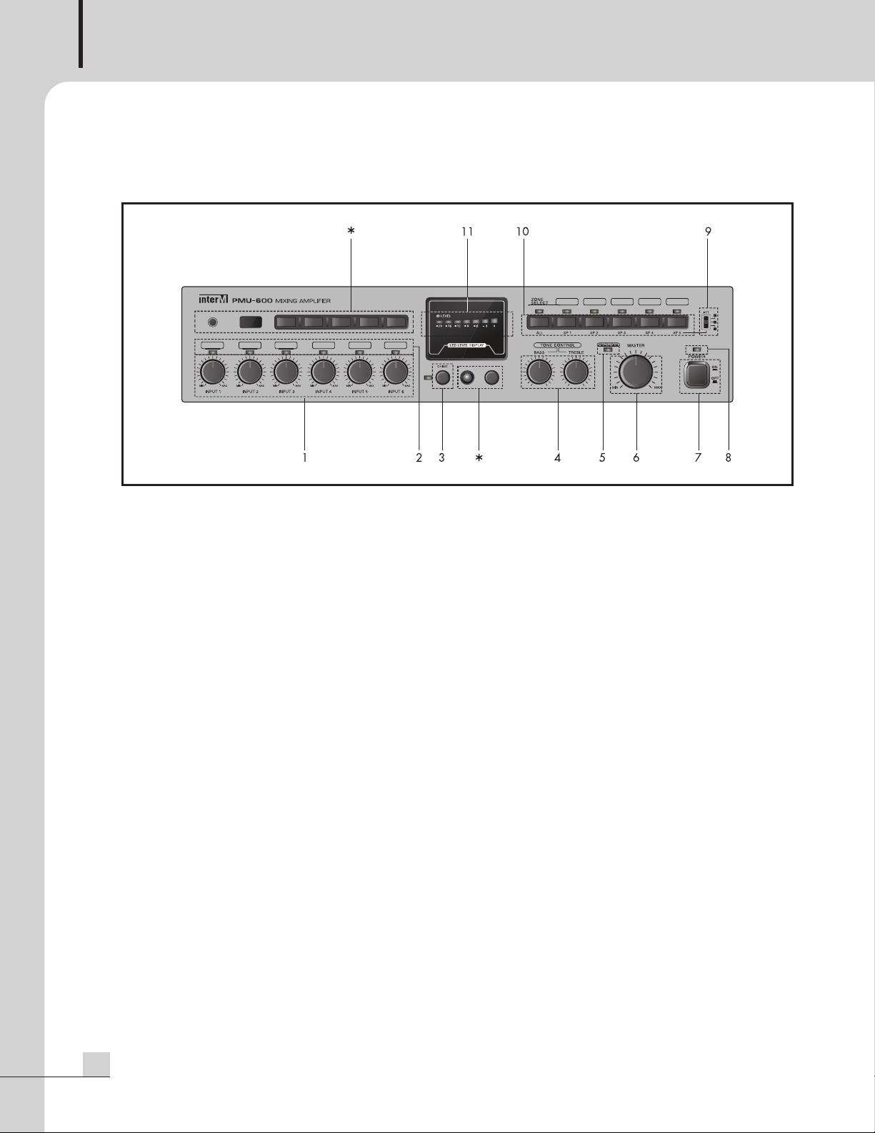
Front Panel
1. INPUT LEVEL CONTROL
Controls the level of each of the six input channels.
2. INPUT SIGNAL INDICATOR
These LEDs light green when input signal is present.
3. CHIME SWITCH
It activates the four tone chime circuitry. The chime indicator lights green when chime is on use.
4. TONE CONTROL
Controls the bass (100Hz) and treble (10KHz) tones of the main amplifier output.
5. PROTECTION MODE INDICATOR
Indicated that the amplifier is in failure protection mode.
6. MASTER VOLUME CONTROL
The master volume control to collectively control the sound level of all outputs and by turning the knob
clockwise to increase the volume and counterclockwise to decrease it.
7. POWER SWITCH
8. POWER INDICATOR
This LED Lights green when the unit is powered on.
* This terminal and switch is used on the advanced model PMU-360N/480N/600N.
It is not availiable for this product.
4
PMU-360/480/600
Page 7

MIXING AMPLIFIER
9. ATTENUATOR
Built-in ATTENUATOR over zone 5, It allows to decrease the output volume independently from master
volume.
Mode 100V Output 70V Output
Switch mode 1 100V 70V
Switch mode 2 70V 49V
Switch mode 3 50V 35V
※Caution : ZONE 5 is output terminal with ATTENUATOR function, and a recommended speaker is lower than
50W(total impedance is upper than 200ohm). Please be careful of connecting the speakers.
10. ZONE SELECTION SWITCH
Use the zone selection switches to route the program audio from the amplifier output to speaker zone 1
through zone 5. The All button controls turns ON/OFF all zones. The Indicators lights on when zone
selection switches indicates if the zone is on.
11. OUTPUT LEVEL DISPLAY
Displays the output level meter, each bar is marked in intervals of 3 to 5dB.
PMU-360/480/600
5
Page 8

MIXING AMPLIFIER
Rear Panel
Rear Panel
1. AC MAINS (AC INLET)
It accepts a standard IEC mains cable, provided.
2. REMOTE CHIME SWITCH TERMINAL
This terminal is used to activate the 4 tone chimes remotely.
3. MANUAL MUTE TERMINAL
When these two terminals are shorted, the output signal is blocked and the protection indicator on the front
panel flashes.
4. VCA (VOLTAGE CONTROLLED AMPLIFIER) TERMINAL
These two terminals provide connection for an external potentiometer. When the potentiometer is connected,
it allows for remote control of the master volume level.
Note that individual input volume control positions limit the maximum output level adjustable with the remote
volume control.
※Make sure not to set the main volume control to minimum level.
- Connection of remote volume control
Remote Volume
Volume Control
※Note : Negative terminal should not be grounded. Never connect it to the unit's chassis or other circuit
6
PMU-360/480/600
10KΩ
ground.
Page 9

MIXING AMPLIFIER
5. TEL IN TERMINAL
his terminal is provided for connection with a telephone exchange system for paging purposes.
T
※NOTE : When the telephone input is active, all other input signal except AMP IN are muted.
6. TEL IN VOLUME CONTROL
It controls the volume of the TEL IN.
7. TEL IN PRIORITY VOLUME CONTROL
It controls the mute level of all other input signal when the TEL IN signal is present
8. INPUT 1~6
INPUT 1~6 are utilized to connect various external sound source devices including MIC, CD, TUNER, and
other.
1) INPUT 1~3 are provided on balanced XLR JACKs and EURO Terminals Each input have a 3 position level
and phantom power selector switch.
- LINE: used for LINE level signal input.
- MIC: used for the MIC level signal input such as dynamic mics.
- PHANTOM: used to power condenser type mics with DC 24V.
※NOTE : Because INPUT 1~3 XLR Jacks are in parallel with the Euro terminal, do not use them
simultaneously.
2) INPUT 4~5 are provided on balanced TRS inch JACKs. Each input has a 2 position level selector switch.
- LINE: used for LINE level signal input.
- MIC: used for the MIC level signal input such as dynamic mics.
3) INPUT 6 is provided on stereo summing RCA JACKs.
9. PRIORITY VOLUME CONTROL
It controls the priority control volume when the signal is inputted to the INPUT 1~2, EXT IN, CHIME and
SIREN.
※The signal from INPUT 1~2, EXT IN, CHIME input has priority over all other input signal and BGM
broadcasting.
10. EXT IN
This line-level input connects an external mixer to the amplifier expanding input channels.
11. MIX OUT
This line-level output connects the amplifier to an external processing unit or recorder.
12. SPEAKER OUTPUT TERMINAL
V
0
V
0
0
t
u
p
t
u
O
r
e
k
a
e
p
S
W
O
l
a
n
i
m
r
e
T
t
u
p
t
u
O
0
6
3
-
U
M
P
0
8
4
-
U
M
P
0
0
6
-
U
M
P
※Please note that SP 1~5 terminal will be controlled by speaker selector switch of front panel.
L
8
/
V
6
7
8
/
V
8
8
/
V
0
0
1
1
W
O
Z
-
H
G
I
Z
-
Ω
8
+
Ω
Ω
8
+
Ω
Ω
8
+
Ω
8
H
Ω
8
2
/
V
0
0
1
Ω
1
2
/
V
0
0
1
Ω
6
1
/
V
0
0
1
L
8
/
V
0
7
8
/
V
0
7
8
/
V
0
7
7
Z
-
H
G
I
Z
-
Ω
8
+
Ω
Ω
8
+
Ω
Ω
8
+
Ω
H
Ω
4
1
/
V
0
7
Ω
0
1
/
V
0
7
Ω
8
/
V
0
7
PMU-360/480/600
7
Page 10

MIXING AMPLIFIER
Speaker Connection
Speaker Connection
Before connecting speakers to the unit, be sure to disconnect the AC power cable.
Make certain that the total impedance is not less than the rated impedance indicated.
- 8Ω Impedance
- High Impedance
8
PMU-360/480/600
Page 11

MIXING AMPLIFIER
※Warning : For high impedance systems, connect with matching transformer as the following Figure. Be
ertain that the total impedance does not equal less than the rated impedance.
c
SP 5 is output terminal with ATTENUATOR function, and a recommended speaker is lower than
50W(total impedance is upper than 200ohm). Please becareful of connecting the speakers.
Low Impedance (100V) (70V)
PMU-360 8Ω+8Ω 28Ω 14Ω
PMU-480 8Ω+8Ω 21Ω 10Ω
PMU-600 8Ω+8Ω 16Ω 8Ω
Please do not use a
8Ω+8Ω
and SP1~SP5 terminal at the same time.
PMU-360/480/600
9
Page 12

MIXING AMPLIFIER
A
C INPUT
System Connection
System Connection
10
PMU-360/480/600
Page 13

Block Diagram
Block Diagram
MIXING AMPLIFIER
PMU-360/480/600
11
Page 14

MIXING AMPLIFIER
Specifications
Specifications
PMU-360 PMU-480 PMU-600
Rated Output Power 360W 480W 600W
Frequency Response (SP OUT/1W output) 80Hz~15kHz
T.H.D (Rated Output, 1kHz) Less than 0.5%
S/N (Rated Output) More than 80dB
Tone Control (100Hz, 10kHz) ±10dB
Input Sensitivity/ Input 1~5 MIC -50dBu/2kΩ
Impedance
Input 6 -10dBu/10kΩ
LINE -10dBu/2kΩ
TEL IN 0dBu/10kΩ
EXT IN 0dBu/20kΩ
MIX Out/Impedance 0dBu/10kΩ
Speaker Output Level/Impedance LOW-Z 76V/8Ω+8Ω 88V/8Ω+8Ω 100V/8Ω+8Ω
70V/8Ω+8Ω 70V/8Ω+8Ω 70V/8Ω+8Ω
HIGH-Z
Operation Temperature -10°C ~ +40°C
Power Source 100-120VAC or 220-240VAC; 50/60Hz
Power Consumption (1/8W output) 80W 100W 160W
Weight (SET) 5.2kg/11.5lb
Dimensions (SET) 420(W)x88(H)x319(D)mm/16.5(W)x3.5(H)x12.6(D)in
* Design and specification are subject to be changed for the improvement of product quality without pre notice.
100V/28Ω 100V/21Ω 100V/16Ω
70V/14Ω 70V/10Ω 70V/8Ω
(Supplied AC mains transformer depends on country requirements)
12
PMU-360/480/600
Page 15

420
88
319
AC INLET FUNCTION TERMINAL INPUT JACK
S
※ DIMENSIONS
PMU-360/480/600
MIXING AMPLIFIER
PMU-360/480/600
13
Page 16

MIXING AMPLIFIER
Service
Service
Procedures
Take steps to insure the problem is not related to operator error or other products within the system. Information
provided in the troubleshooting portion of this manual may help with this process. Once it is certain that the
problem is related to the product contact your warranty provider as described in the warranty section of this
manual.
Schematic
A Schematic is available by contacting your warranty provider.
Parts List
A Parts List is available by contacting your warranty provider.
Variations and Options
Variations and Options
Variations
Products supplied through legitimate sources are compatible with local AC power requirements.
Options
No optional items are available for this product.
Warranty
Warranty
Warranty terms and conditions vary by country and may not be the same for all products. Terms and conditions
of warranty for a given product may be determined first by locating the appropriate country which the product
was purchased in, then by locating the product type.
To obtain specific warranty information and available service locations contact Inter-M directly or the
authorized Inter-M Distributor for your specific country or region.
14
PMU-360/480/600
Page 17

NOTE
PMU-360/480/600
3
Page 18

NOTE
Page 19

NOTE
PMU-360/480/600
3
Page 20

Inter-M, Ltd. (Korea) began operations in 1983.
Since then, Inter-M has grown to become one of the largest manufacturers
of professional audio and commercial sound electronics equipment in the world.
Inter-M has gained worldwide recognition for its own branded products,
as well as private label manufacturing of electronics sold under other names (OEM).
The company is no longer just a Korean company, but rather a global company
that is truly international in scope, with factories and offices in Korea and China,
and sales and marketing operations located in Japan, Europe, and the U.S.A.
With more than 850 employees around the globe,
Inter-M is well-poised for further growth and expansion.
Inter-M Americas, INC.
13875 ARTESIA BLVD. CERRITOS, CA 90703 USA
TEL : +1-562-921-0313, FAX : +1-562-921-0370
Home Page : http://www.inter-m.net, E-mail : info@inter-m.net
Inter-M Corporation
SEOUL OFFICE:653-5 BANGHAK-DONG, DOBONG-GU, SEOUL, KOREA
TEL : +82-2-2289-8140~8, FAX : +82-2-2289-8149
Home Page : http://www.inter-m.com, E-mail : overseas@inter-m.com
MADE IN KOREA
September 2013 133870
 Loading...