

Page 1

TruVision NVR 50 User
Manual
P/N 10725604-EN • REV B • ISS 18MAR13
Page 2

Copyright
©
Interlogix is part of UTC Climate Controls & Security, a unit of United
Technologies
Trademarks and
patents
The
Other trade names used in this document may be trademarks or registered
trademarks of
Manufacturer
UTC Fire & Security Americas Corporation, Inc.
2955 Red Hill Avenue, Costa Mesa, CA 92626
Authorized EU manufacturing representative:
UTC Fire & Security B.V.
Kelvinstraat
Certification
FCC compliance
This device complies with part 15 of the FCC Rules. Operation is subject to the
following two conditions: (1) This device may not cause harmful interference,
and (2) this device
that may cause undesired operation.
FCC compliance
Class B: This equipment has been tested and found to comply with the limits for
a Class B digital device, pursuant to part 15 of the FCC Rule
designed to provide reasonable protection against harmful interference in a
residential installation. This equipment generates, uses, and can radiate radio
frequency energy and, if not installed and us ed in acc ordanc e with the
instructi
There is no guarantee that interference will not occur in a particular installation.
If this equipment does cause harmful interference to radio or television
reception, which can be determined by
user is encouraged to try to correct the interference by one or more of the
following measures:
•
•
•
•
Notice!
cause radio interference in which case the us er m a y be required to take
adequate measures.
European Union
directives
12004/108/EC (EMC directive):
device is in compliance or with the essential requiremen
provisions of Directive 2004/108/EC.
2002/96/EC (WEEE directive):
disposed of as unsorted municipal waste in the European Union. For proper
recycling, return this product to your local su
equivalent new equipment, or dispose of it at designated collection points. For
more information see: www.recyclethis.info.
2006/66/EC (battery directive):
disposed of as
product documentation for specific battery information. The battery is marked
with this symbol, which may include lettering to indicate cadmium (Cd), lead
(Pb), or mercury (Hg). For proper recycling,
to a designated collection point. For more information see: www.recyclethis.info.
Contact information
For contact information, see www.utcfireandsecurity.com.
2013 UTC Fire & Security Americas Corporation, Inc.
Corporation. All rights reserved.
TruVision NVR 50 and logo are trademarks of United Technologies.
the manufacturers or vendors of the respective products.
-5923, USA
7, 6003 DH Weert, The Netherlands
N4131
must accept any interference received, including interference
s. These limits are
ons, may cause harmful interference to radio communications.
Reorient or relocate the receiving antenna.
Increase the separation between the equipment and receiver.
Connect the equipment into an outlet on a circuit different from that to which
the receiver is connected.
Consult the dealer or an experienced radio/TV technician for help.
ACMA compliance
This is a Class A product. In a domestic environment this product may
Hereby, UTC Fire & Security declares that this
Products marked with this symbol cannot be
unsorted municipal waste in the European Union. See the
This product contains a battery that cannot be
turning the equipment off and on, the
ts and other relevant
pplier upon the purchase of
return the battery to your supplier or
Page 3

Content
Chapter 1 Product introduction 1
Product overview 1
Chapter 2 Installation 3
Installation environment 3
Unpacking the TVN 50 and its accessories 3
Back panel 4
Wiring the keypad 5
RS-485 ports 8
RS-232 port 8
Monitor connections 8
Audio inputs and output 8
Brackets 9
Chapter 3 Getting started 11
Turning on and off the NVR 11
Using the setup wizard 12
Chapter 4 Operating instructions 17
Controlling the TVN 50 17
Using the front panel 17
Using the mouse 19
Using the IR remote control 20
Menu overview 22
Chapter 5 Live view 27
Description of live view 27
Video output 27
Audio output 28
Controlling live view mode 28
Multiview format 30
Sequencing cameras 31
Accessing frequently used commands 31
Configuring live view 33
General settings 36
Configuring time and date 38
Chapter 6 Controlling a PTZ camera 41
Configuring PTZ settings 41
Calling up presets, tours and shadow tours 42
Setting and calling up presets 43
Setting and calling up preset tours 45
Setting and calling up a shadow tour 47
TruVision NVR 50 User Manual i
Page 4

Chapter 7 Playing back a recording 49
Overview of the playback window 49
Instant playback 51
All-day playback 52
Searching recorded video 53
Playing back recordings by time and video type 54
Playing back recordings by event 55
Creating and playing back bookmarked recordings 56
Slideshow of snapshots 57
Playing back recordings from the system log 57
Playing back frame-by-frame 58
Digital zoom in playbac k 59
Chapter 8 Archiving recorded files 61
Archiving files 61
Creating and archiving video clips 64
Archiving snapshots 64
Managing backup devices 65
Playing back archived files on a PC 65
Chapter 9 Using the web browser 67
Windows Vista and 7 users 67
Accessing the web browser 68
Web browser overview 68
Using the web browser to configure the device 70
Searching and playing back recorded video 71
Searching for event log s 73
Controlling a PTZ dome camera in the web browser 73
Capturing text insertions 74
Text overlay 75
Using a network storage system 75
Chapter 10 Recording 77
Initializing recording settings 77
Defining a recording schedule 79
Daily schedules 80
Holiday schedules 82
Motion detection schedules 82
External alarm schedules 83
Protecting recorded files 83
Configuring redundant recording 85
Chapter 11 Alarm settings 87
Description of alarm notification types 87
Setting up motion detection 88
Setting up external alarms 90
Triggering or cleari ng alarm out puts ma nually 93
Setting up system notifications 93
ii TruVision NVR 50 User Manual
Page 5

Detecting video loss 94
Detecting video tampering 94
Chapter 12 Network settings 97
Configuring general network settings 97
Configuring PPPoE 98
Configuring DDNS 99
Configuring an NTP server 99
Configuring e-mail 100
Configuring SNMP 101
Configuring the FTP server 101
Configuring a remote alarm host 101
Configuring multicast 102
Configuring the server and HTTP ports 102
Configuring the RTSP service port 102
Checking network status 103
Exporting network packet data 104
Port forwarding 104
Chapter 13 HDD management 105
Initializing HDDs 105
Controlling disk space on the HDD 105
Setting up HDD groups 106
Setting the HDD property 107
Checking HDD status 107
Configuring HDD alarms 108
Managing eSATA 108
Checking the S.M.A.R.T. information 108
Chapter 14 Camera settings 111
Configuring the camera OSD settings 111
Setting up privacy masking 112
Adjusting video image settings 113
Chapter 15 NVR management 115
Configuring the RS-232 port 115
Updating system firmw ar e 116
Restoring default settings 117
Viewing system information 117
Searching system logs for events 119
Chapter 16 User management 121
Adding a new user 121
Customizing a user’s access privileges 122
Deleting a user 124
Modifying a user 124
Changing the Admin password 124
TruVision NVR 50 User Manual iii
Page 6

Chapter 17 iTVRmobile 125
Setup and login 125
Live view 126
Controlling a PTZ camera 127
Device management 129
Favorites 130
Local configuration 130
Change passwords 130
Snapshots 130
Appendix A Specifications 131
Appendix B PTZ protocols 133
Appendix C Port forwarding information 135
Appendix D KTD-405 keypad 137
Supported firmware 137
Wiring the keypad 137
Setting up the keypad to work with the TVN 50 138
Operating the keypad 140
Appendix E Maximum pre-recording times 145
Appendix F Supported PTZ commands 147
Appendix G Default menu settings 149
Glossary 157
Index 159
iv TruVision NVR 50 User Manual
Page 7

TVN
TVN
TVN
TVN
TVN
TVN
TVN
TVN
TVN
TVN
Chapter 1
Product introduction
Product overview
This is the TruVision NVR 50 (TVN 50) User Manual for models:
Table 1: Product codes
-5032-4T TruVision TVN 50, 32 channels, 4 TB storage, North American power cord
-5032-8T TruVision TVN 50, 32 channels, 8 TB storage, North American power cord
-5032-12T TruVision TVN 50, 32 channels, 12 TB storage, North American power cord
-5032-16T TruVision TVN 50, 32 channels, 16 TB storage, North American power cord
-5032-2TEA TruVision TVN 50, 32 channels, 2 TB storage, EU + UK power cords
-5032-4TEA TruVision TVN 50, 32 channels, 4 TB storage, EU + UK power cords
-5032-8TEA TruVision TVN 50, 32 channels, 8 TB storage, EU + UK power cords
-5032-12TEA TruVision TVN 50, 32 channels, 12 TB storage, EU + UK power cords
-5032-16TEA TruVision TVN 50, 32 channels, 16 TB storage, EU + UK power cords
-5032-4TAZ TruVision TVN 50, 32 channels, 4 TB storage, ANZ power cords
The TruVision™ NVR 50 is a versatile, user-friendly embedded network video
recorder (NVR) allowing end-users to record up to 32 cameras with a maximum
total input bandwidth of 80Mbps, while providing integration with the UTC
portfolio of security solutions, and offering a seamless product experience within
the TruVision brand.
Its dual streaming functionality allows the user to set up different settings for
recording and streaming video in live view mode.
The TruVision NVR 50 can fully integrate with the license-free TruVision
Navigator software, which is ideal for most commercial applications. TVN 50’s
easy and intuitive-to-use web browser interface enables remote configuration
and secure viewing, searching, and playing back of video from computers
connected via the Internet.
TruVision NVR 50 User Manual 1
Page 8

0BChapter 1: Product introduction
2 TruVision NVR 50 User Manual
Page 9

Chapter 2
Installation
This section describes how to install the TVN 50 unit.
Installation environment
When installing your product, consider these factors:
• Ventilation
• Temperature
• Moisture
• Chassis load
Ventilation: Do not block any ventilation openings. Install in accordance with the
manufacturer’s instructions. Ensure that the location planned for the installation
of the unit is well ventilated.
Temperature: Consider the unit’s operating temperature (-10 to +55 ºC, 14 to
131 °F) and noncondensing humidity specifications (10 to 90%) before choosing
an installation location. Extremes of heat or cold beyond the specified operating
temperature limits may reduce the life expectancy of the NVR. Do not install the
unit on top of other hot equipment. Leave 44 mm (1.75 in.) of space between
rack-mounted TruVision NVR 50 units.
Moisture: Do not use the unit near water. Moisture can damage the internal
components. To reduce the risk of fire or electric shock, do not expose this unit to
rain or moisture.
Chassis: Equipment weighing less than 15.9 kg (35 lb.) may be placed on top of
the unit.
Unpacking the TVN 50 and its accessories
When you receive the product, check the package and contents for damage, and
verify that all items are included. There is an item list included in the package. If
any of the items are damaged or missing, please contact your local supplier.
TruVision NVR 50 User Manual 3
Page 10

1BChapter 2: Installation
Items shipped with the product include:
• IR (infrared) remote control
• Two AAA batteries for the remo te c ontr ol
• AC power cords
• USB mouse
• NVR
• CD with software and manuals
• TruVision NVR 50 Quick Start Guide
• TruVision NVR 50 User Manual (on CD)
Back panel
Figure 1 on page 5 shows the back panel connections and describes each
connector on a typical TVN 50 network video recorder. Details may vary for
specific models.
Before powering up the NVR, connect the cameras and a main monitor for basic
operation.
4 TruVision NVR 50 User Manual
Page 11
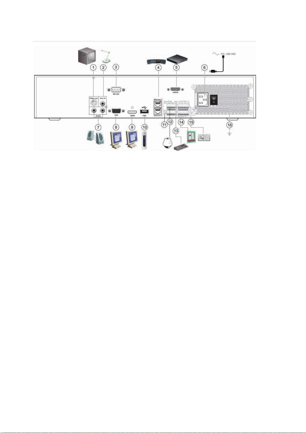
1BChapter 2: Installation
16. Connect to ground.
Figure 1: Back panel connections
1. Connect one CCTV monitor (BNC-type
connectors): Main monitor.
2. Connect one audio input to RCA
connectors.
3. Connect to a RS-232 de vic e.
4. Connect to a network.
5. Connect to an optional eSATA device such
as SATA HDD, CD/DVD-RM.
6. Connect to a power cord.
7. Connect to speakers for audio output.
8. Connect to a VGA monitor.
9. Connect to an HDTV. The HDMI
connection supports both digital audio and
video.
10. Connect to an optional USB device such as
a mouse, CD/DVD burner or HDD.
11. Terminate the line to the dome cameras
using this RS-485 switch. Default is Off.
12. Connect to a PTZ control.
13. Connect to a keyboard (KTD-405 shown).
14. Connect up to 16 alarm input cables to
relay outputs.
15. Connect up to four alarm relay outputs.
Wiring the keypad
The keypad uses RS-485 simplex wiring. The signal is transferred by a single
twisted pair line. A shielded STP CAT5 network cable is recommended. Ground
one end of the cable, either the first or last device on the RS-485 line.
The maximum number of devices that can be installed in one bus is 255, with a
maximum cable length of 1200 m. The cable length can be expanded using a
signal distributor.
Both the first and the last device in series should be terminated with 120 Ohm
resistance to minimize line reflections. See Figure 2 below.
TruVision NVR 50 User Manual 5
Page 12
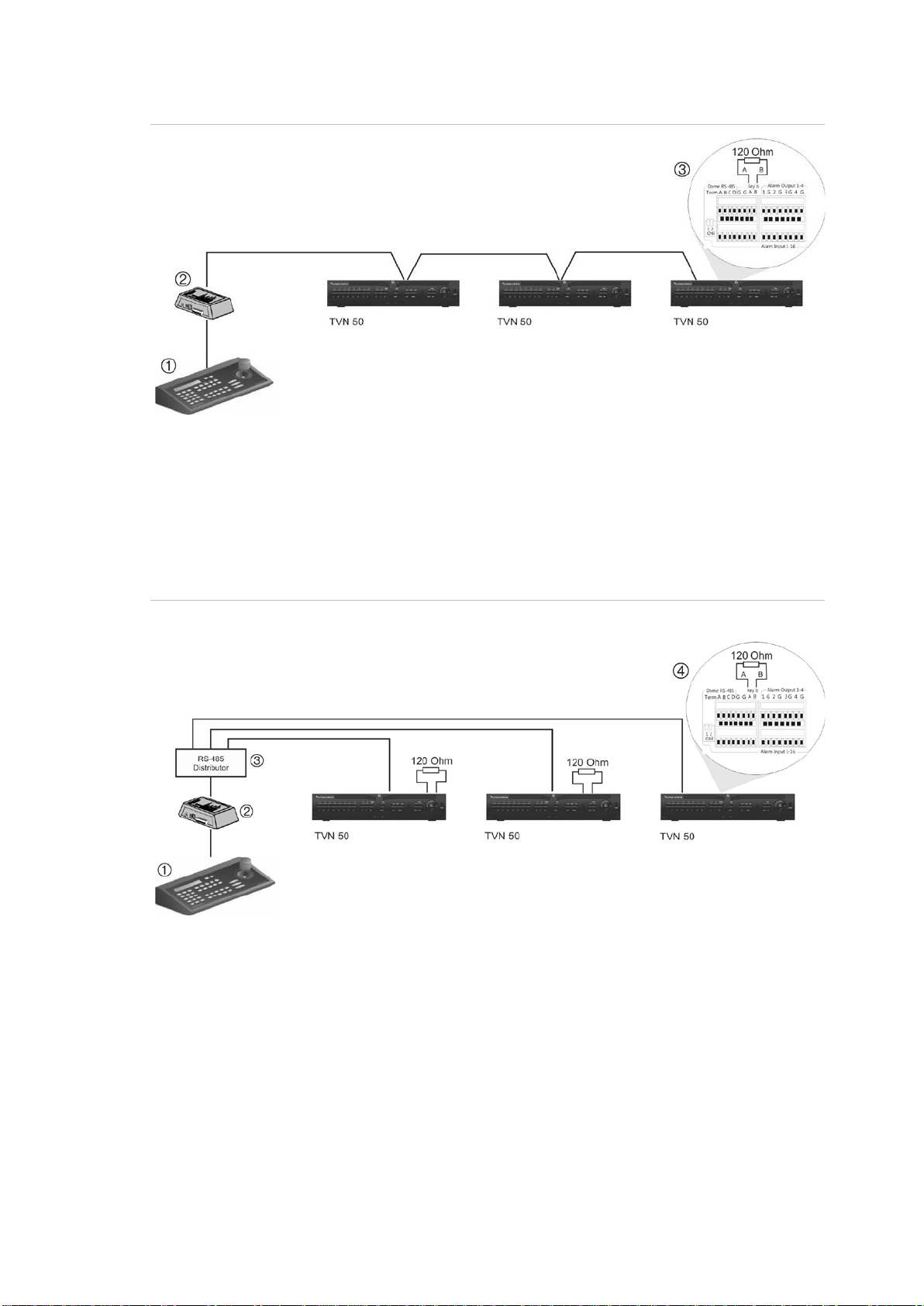
1BChapter 2: Installation
2. I/O box
2. I/O box
4. See section “RS-485 ports” on page 8
Figure 2: RS-485 bus serial wiring (KTD-405 keypad shown)
1. Keypad
3. See section “RS-485 ports” on page 8
Use an RS-485 signal distributor for a star wiring configuration. See Figure 3 on
page 6.
Figure 3: Star wiring with RS-485 signal distributor
Correct:
1. Keypad
6 TruVision NVR 50 User Manual
3. RS-485 distributor
Page 13
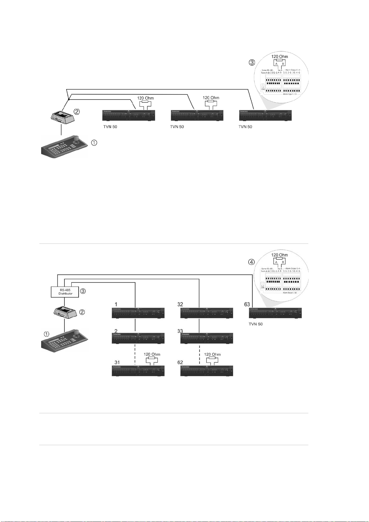
1BChapter 2: Installation
2. I/O box
2. I/O box
4. See section “RS-485 ports” on page 8
Incorrect:
1. Keypad
3. See section “RS-485 ports” on page 8
Use an RS-485 signal distributor to increase the maximum number of devices on
the bus as well as the total range. Each distributor output provides another RS485 bus, extending the output an addi tional 1200 m. Up to 31 NVRs can be
connected to each output. See Figure 4 below.
Figure 4: Expanding the system with an RS-485 signal d istributor
1. Keypad
Caution: Most signal distri butor s are uni dir ec t i onal . This me ans that the signal
only flows from the input towards the outputs. Consequently it is not possible to
connect several keypads.
See section “RS-485 p ort s” below to configure the RS-485 port communication
settings.
TruVision NVR 50 User Manual 7
3. RS-485 distributor
Page 14
1BChapter 2: Installation
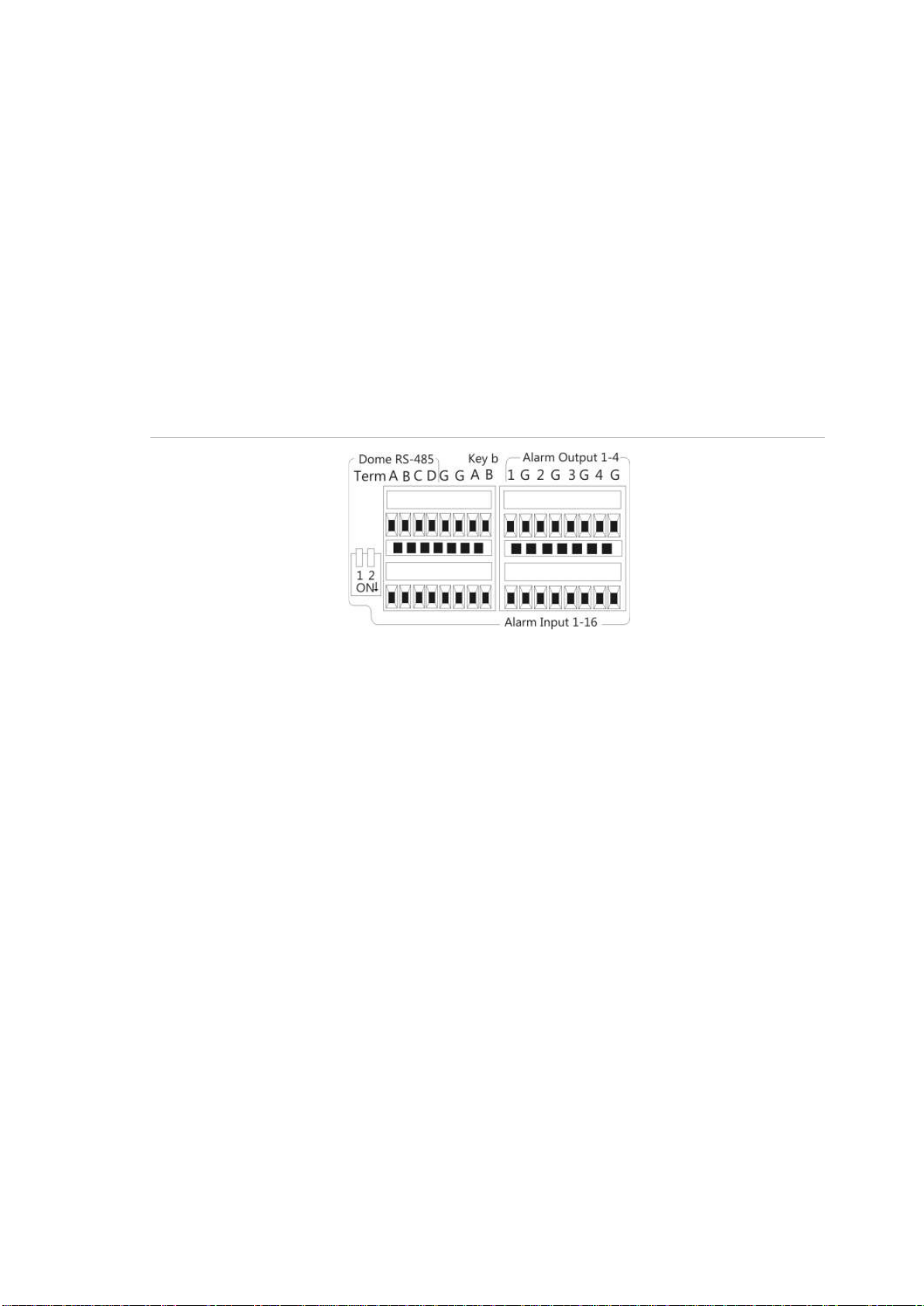
RS-485 ports
There are two RS-485 ports on the rear panel of the NVR. See Figure 5 below for
the serial pin outs.
• Dome RS-485:
A and B: Connect pan, tilt, zoom control of PTZ dome cameras. A = +, B = C and D: Not used
G: Ground of dome camera
G: Ground of keypad
• Keyb: Connect the keypad.
Figure 5: RS-485 pins
RS-232 port
Use the RS-232 port to connect CBR-PB3-POS (point-of-sale) and ATM devices
to the NVR.
Monitor connections
Connect the unit to a monitor via a 75-ohm video coaxial cable with the BNC
connector. The unit provides a 1 Vp-p CVBS signal. See Figure 1 on page 5 for
connecting a monitor to a TVN 50.
The TVN 50 supports up to 1920 × 1080 / 60 Hz resolution in VGA. The monitor
resolution should be at least 800 × 600. Adjust your monitor accordingly to this
resolution.
Audio inputs and output
The unit is equipped with 1 audio input and two audio outputs. Both the audio
outputs and the audio inputs are line-level.
8 TruVision NVR 50 User Manual
Page 15
1BChapter 2: Installation
Audio input
Audio output
RCA jack, 315 mV, 40 kohms. Unbalanced
RCA jack, 315mV, 600 ohms. Unbalanced
Note: Line-level audio requires amplification.
Brackets
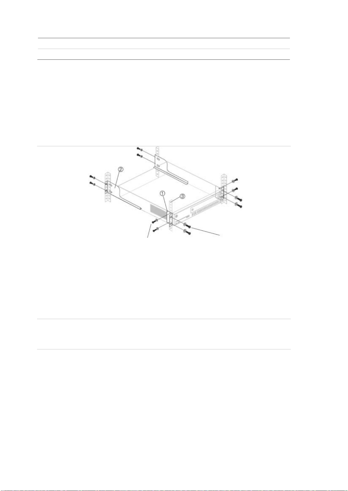
The NVR is easily rack-mountable with the purchase of the TVR-RK-1 rackmount kit. See Figure 6 below. Contact your local supplier to order it.
Figure 6: Rack-mount installation
Attach the small front rack ears to the unit
(screws supplied)
Attach the NVR to the front rails
(screws not included)
To install the racks:
1. Attach the two small front-rack mou nt ear s to the NVR (screws supplied).
2. Attach the two large rear support brackets (not supplied) to the rear rails.
3. Attach the NVR to the front rails (screws not supplied).
Caution:
Do not rack-mount the TVN 50 without the rear rails installed. Failure to install
the rear rails can damage the NVR.
TruVision NVR 50 User Manual 9
Page 16

1BChapter 2: Installation
10 TruVision NVR 50 User Manual
Page 17

Chapter 3
Getting started
Turning on and off the NVR
Before starting the power up process, connect at least one monitor to the video
out or the VGA interface. Otherwise, you will not be able to see the user interface
and operate the device.
The TVN 50 auto-detects the video mode (PAL or NTSC) on startup.
It is equipped with a universal power supply that will auto-sense 110/240 V,
60/50 Hz.
Note: It is recommended that an uninterruptible power supply (UPS) is used in
conjunction with the device.
To turn on the NVR:
Turn on the NVR using the power switch on the back panel. The power LED
illuminates. A splash screen appears indicating that the NVR is starting up.
Once the NVR is powered up, the indicator bar on the front panel will light up
green. The Start Up Wizard window will appear.
To turn off the NVR:
1. In live view mode, right-click the mouse and click Menu. The main menu
screen appears.
2. Select the Power Manager icon.
3. In the Shutdown popup menu, select Shutdown. Click Yes to confirm
shutdown.
To reboot the NVR:
1. In live view mode, right-click the mouse and click Menu. The main menu
screen appears.
2. Select the Power Manager icon.
3. In the Shutdown popup menu, select Reboot. Click Yes to confirm shutdown.
TruVision NVR 50 User Manual 11
Page 18

2BChapter 3: Getting started
Using the setup wizard
The TVN 50 has an express installation wizard that lets you easily configure
basic NVR settings when first used. It configures all cameras simultaneously.
The configuration can then be customized as required.
By default the setup wizard will start once the NVR has loaded. It will walk you
through some of the more important settings of your NVR.
Any changes you make to a setup configuration page are saved when you exit
the page and return to the main wizard page.
Note: If you want to set up the NVR with default settings only, click Next in each
screen until the end.
To quickly set up the TVN 50:
1. Connect all the devices required to the back panel of the NVR. See Figure 1
on page 5.
2. Turn on the unit using the power switch on the back panel.
3. Select the preferred language for the system from the dropdown list and then
click Next.
4. Enable or disable the option to start the wizard automatically when the NVR is
turned on. Click Next.
5. Administrator configuration:
Navigate to the Admin Passw or d edit box and click the edit box with the
mouse, or press Enter on the front panel or remote control, to display the
virtual keyboard. Enter the de faul t ad min password, 1234.
Note: You must enter an admin password. To change the Admin password,
check New Admin password and enter the new password and confirm it.
Caution: It is strongly recommended that you change the password of the
administrator. Do not leave 1234 as the default password. Write it down in a
safe place so that you do not forget it.
If you should forget the password to your NVR, contact your supplier with the
serial number of your NVR to obtain a secure code to reset your NVR.
Click Next.
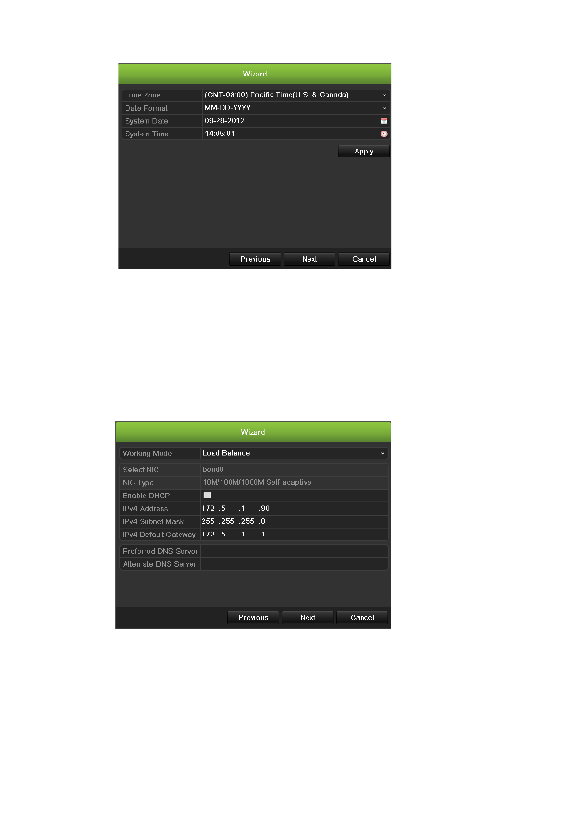
6. Time and date c onfi guration:
Select the desired time zone, date format, system time and system date.
Note: Daylight savings time (DST) cannot be configured from the Wizard. See
“Configuring time and date” on page 38 for more information on DST.
12 TruVision NVR 50 User Manual
Page 19
2BChapter 3: Getting started
Note: The system time and date are visible on screen. However, they do not
appear in recordings.
Click Next to move to the next page, or Previous to return to the previous
page.
7. Network configuration:
Configure your network settings such as the NIC type, Enable or Disable
DNCP,IP address, subnet mask and default gateway. Enter the preferred
DNS server address as well as the alternate one to use.
Click Next to move to the next page, or Previous to return to the previous
page.
8. HDD management:
Configure your HDD settings as required.
You can group HDDs and assign cameras to a group. See “Setting up HDD
groups” on page 106 for further information. You can also set up a drive for
redundant recording . See “Configuring redundant recording” on page 85.
TruVision NVR 50 User Manual 13
Page 20
2BChapter 3: Getting started
After configuring your HDD settings, click Initialize and Next to move to the
next page, or Previous to return to the previous page.
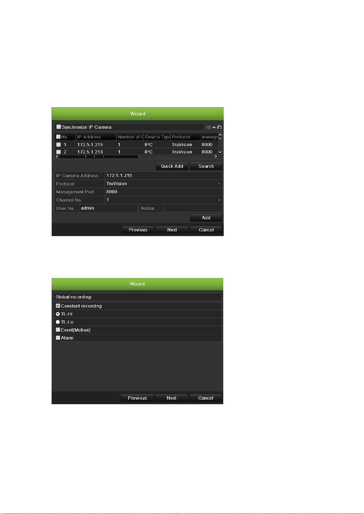
9. Adding IP Camera:
Click Search to find any online cameras. Select the IP camera to be added,
enter User name and Admin password, then click the Add button. Click, Next
to move to the Recording Configuration screen.
10. Recording configuration:
Configure your recording settings as required. The settings apply to all
cameras connected to the NVR.
Check the Constant Recording checkbox for the NVR to record continuously
all day. If left unchecked, the NVR will not record.
Check the TL-Hi check box and select its image resolution and frame rate.
Check the TL-Lo check box and select its image resolution and frame rate.
To record motion det e c ti on events, check Event (Motion).
14 TruVision NVR 50 User Manual
Page 21
2BChapter 3: Getting started
To record alarm events, check Alarm.
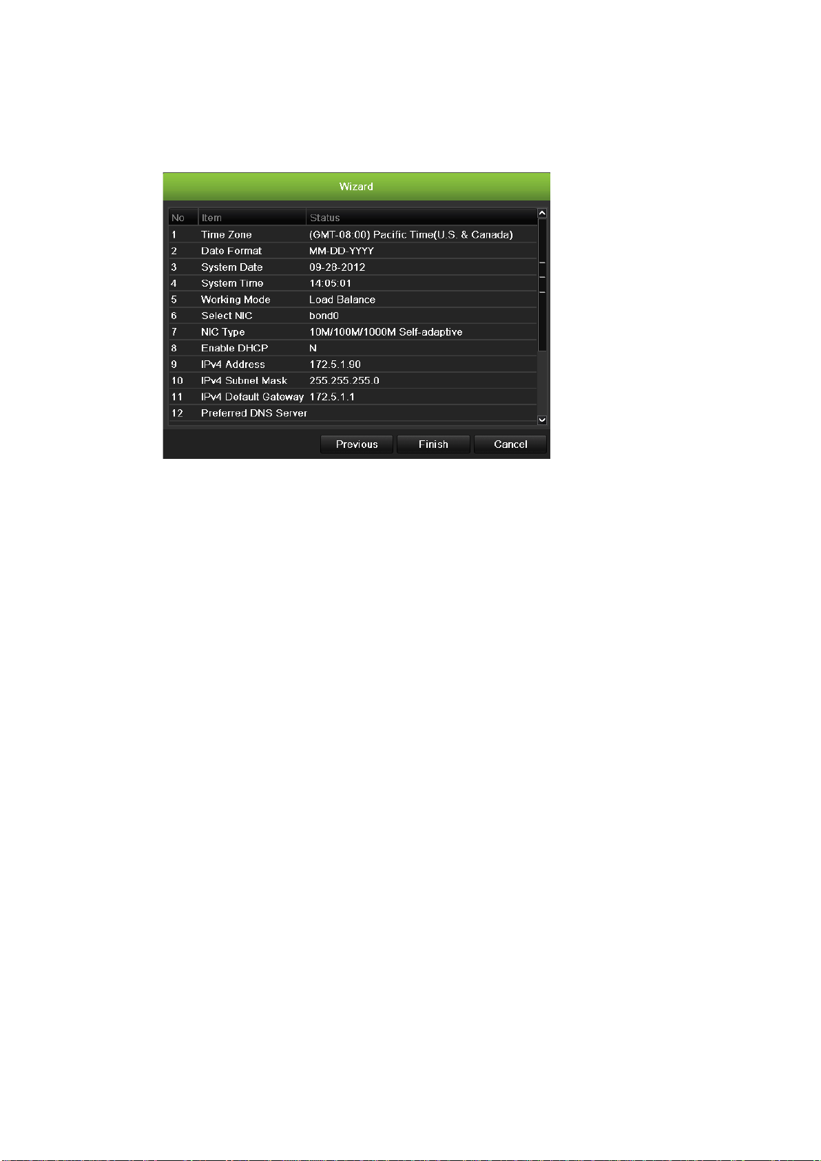
11. When all the required changes have been entered, a page appears showing
all the settings.
Click Finish to exit the Wizard. The NVR is now ready to use.
TruVision NVR 50 User Manual 15
Page 22

2BChapter 3: Getting started
16 TruVision NVR 50 User Manual
Page 23

Chapter 4
Operating instructions
Controlling the TVN 50
There are several ways to control the NVR:
• Front panel control
• Mouse control
• IR remote control
• KTD-405 keypad control (see Appendix)
• Web browser control
You can use your preferred control method for any procedure, but in most cases
we describe procedures using mouse terminology. Optional control methods are
given only when they differ substantially from mouse control method s.
Using the front panel
The function buttons on the front panel control can be used to operate many, but
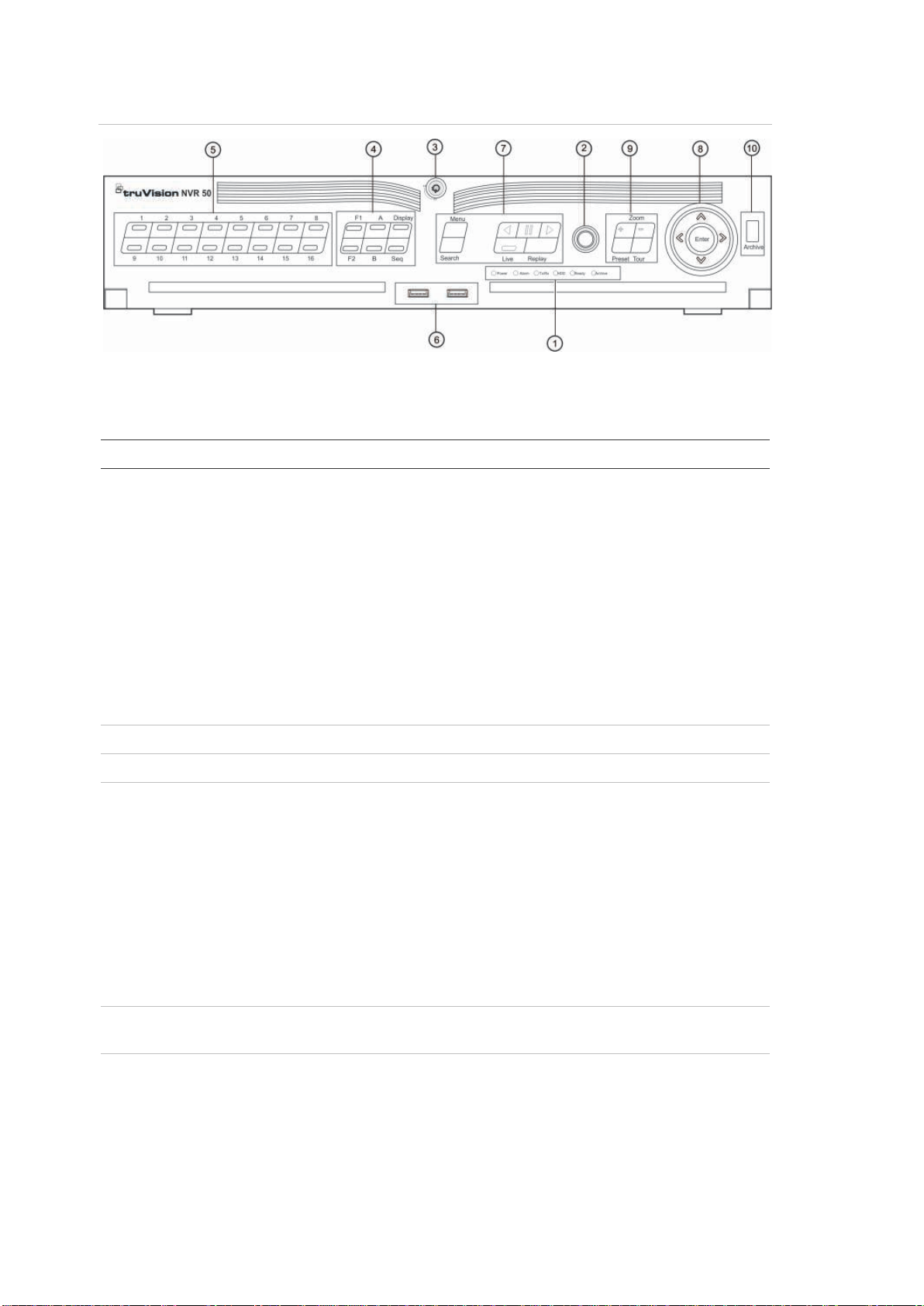
not all, of the main functions of the NVR. The LED indicators light up or flash to
alert you of various conditions. The functions available can be limited by setting
passwords. See Figure 7 below for more in for mation.
TruVision NVR 50 User Manual 17
Page 24
3BChapter 4: Operating instructions
Item
1.
2.
3.
4.
5.
6.
Figure 7: Front panel
The controls on the front panel include:
Table 2: Front Panel Elements
Name Description
Status LEDs Power: Green indicates the NVR is working correctly.
Red indicates a fault.
Alarm: Indicates an external alarm status or motion.
Tx/Rx: Tx/Rx indicator blinks green when network
connection is functioning properly.
HDD: HDD indicator blinks red when data is being read
from or written to the HDD.
Ready: Green indicates the device is functioning
properly.
Archive: Archive indicator blinks green when record
files or snapshots are being exported to a USB or
eSATA device.
IR receiver Receiver for IR remote.
Front Panel Lock You can lock or unlock the front panel with a key.
Display buttons Display: Toggles through the various multiviews: full,
quad, 1+5, 1+7, 9, and 16.
Sequence: Starts/stops sequencing in live view mode.
A: Selects monitor VGA/A in live view mode
B: Selects monitor A/B in live view mode
F1: In all-day playback, click to start and stop video
clipping.
F2: In live view mode, click to display/hide the time bar.
In all-day playback, click to hide/display the playback
control toolbar.
Numeric buttons Switch between different cameras in live, PTZ control or
playback modes.
USB Interfaces Universal Serial Bus (USB) ports for additional devices
such as a USB mouse and USB Hard Disk Drive (HDD).
18 TruVision NVR 50 User Manual
Page 25

3BChapter 4: Operating instructions
Item
7.
8.
9.
1
Name Description
Menu and Search buttons
Playback buttons
Direction
Enter button The ENTER button is used to confirm selection in any of
Menu: Enter/exit the main menu.
Search: Enter the advanced search menu.
: Jump back to the oldest available video and starts
the playback.
: Pause playback.
: Instantly playback the currently selected file.
Default time is 1 minute.
Live: Switch to live view mode.
Replay: Replay the current file in playback Starts at the
beginning of the file.
The DIRECTION buttons are used to navigate between
different fields and items in menus.
In the Playback mode, the left and right button is used to
speed up and slow down recorded video.
In Live View mode, these buttons can be used to cycle
through channels.
In PTZ control mode, it can control the movement of the
PTZ camera.
the menu modes.
Show the PTZ control toolbar when in live view mode.
In Playback mode, it can be used to play or pause the
video.
In single-frame Playback mode, pressing the button will
advance the video by a single frame.
PTZ buttons Zoom: Use + and – for digital zoom.
Preset: Call up preprogrammed preset positions.
Tour: Call up preprogrammed shadow tours.
0. Archive button Press once to enter quick archive mode. Pres s twice to
start archiving. Indicator blinks green when data is being
written to backup device.
Using the mouse
The USB mouse provided with the TVN 50 can be used to operate all the
functions of the NVR, unlike the front pan el which has limited functionality. The
USB mouse lets you navigate and make changes to settings in the user
interface.
Connect the mouse to the TVN 50 by plugging the mouse USB connector into
the USB port on the front or back panel. The mouse is immediately operational
and the pointer should appear.
Note: Use a USB 1.1 or higher mouse.
TruVision NVR 50 User Manual 19
Page 26

3BChapter 4: Operating instructions
Item
Left
Right button
Scroll
Move the pointer to a command, option, or button on a screen. Click the left
mouse button to enter or confirm a selection.
You can purchase a spare mouse by ordering part number TVR-MOUSE-1
TruVision™ DVR Model 5032 Mouse.
See Table 3 below for a descr ipt ion of the mouse buttons.
Table 3: Mouse buttons
Description
button Single-Click Live view: Select a camera to display the quick
access toolbar (see “Accessing frequently used
commands” on page 31).
Menu: Select a component of a menu, such as a
button or an input field. This is similar to pressing the
Enter button on the remote/front panel controls.
Double-Click Live view: Switch between single screen and multi-
screen mode in live/ playback mode.
Click and Drag Live view: Drag channel/time bar.
PTZ control: Adjust pan, tilt and zoom.
Tamperproof, privacy masking and motion
detection functions: Select the target area.
Digital zoom-in: Drag and select target area.
Single-Click Live view: Display menu.
Menu: Exit the current menu and return to higher
level.
-wheel Scroll Up Live view: Return to the previous screen.
Menu: Move the selection to the previous item.
Scroll Down Live view: Move to the next screen.
Menu: Move the selection to the next item.
Using the IR remote control
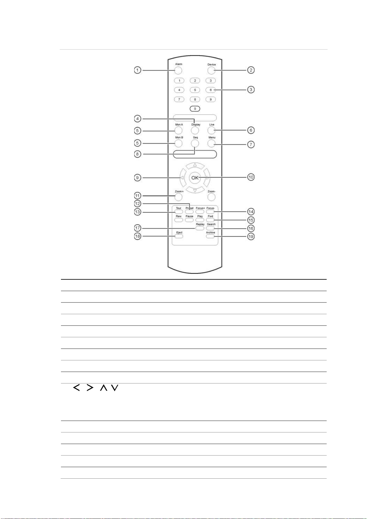
The TVN 50 is supplied with an infra red (IR) remote control unit. Like the mouse,
it can be used to operate all of the main functions of the TVN 50.
The IR remote control can be programmed with a unique device ID address so
that the controller will only be able to communicate with NVRs with that address.
No programming is necessary if using a single TVN 50.
The device ID address only applies when using a remote control and not when
using a keypad.
You can purchase a remote control by ordering part number TVR-REMOTE-1
TruVision™ DVR Model 5032 IR Remote Control.
20 TruVision NVR 50 User Manual
Page 27
3BChapter 4: Operating instructions
Item
Description
1
Acknowledge an alarm.
2
Enable/disable the IR remote control to control the
3
Select a camera, and enter a number in a menu option.
4
Switch between the different multiviews.
5
Switch between monitors A and B.
6
Return to live view mode.
7
Activate the main menu.
8
Start /stop sequencing.
9
In Menu mode: Use left or right arrow
arrow buttons to edit entry.
In PTZ mode: Use to control PTZ.
In Playback mode: Use to control playback speed.
10
Confirm selection.
11
Use to control zoom of camera le
12
Enter preprogrammed three
13
Enter preprogrammed three
14
Use to control focus of camera lens.
Figure 8: IR remote control
. Alarm
. Device
. Numeric buttons
. Display
. Mon A and Mon B
. Live
. Menu
. Seq
. , , ,
. OK
. Zoom + and . Preset
TVN 50.
buttons to select and up or down
ns.
-digit code to call up a preset.
. Tour
. Focus + and -
TruVision NVR 50 User Manual 21
-digit code to call up shadow tour.
Page 28

3BChapter 4: Operating instructions
Item
Description
15
Use to control playback (Rewind, Pause, Play, and Fast Forward).
16
Open the Search menu.
17
Replay the selected file from the beginning.
18
Eject the
19
Press once to enter quick archive mode. Press twice to start archiving.
. Playback control
. Search
. Replay
. Eject
. Archive
CD or DVD disk.
Aim the remote control at the IR receiver located at the front of the unit to test
operation.
To connect the remote control to the TVN 50:
1. Press the Menu button on the front panel or right-click the mouse and select
the Menu button. The main menu screen appears.
2. Click Display Mode Settings > Monitor.
3. Check the device address value. The default value is 255. This device
address is valid for all IR controls.
4. On the remote control press the Device button.
5. Enter the device address value. It must be the same as that on the TVN 50.
6. Press OK on the remote control.
To place batteries into the IR remote control:
1. Remove the battery cover.
2. Insert the batteries. Make sure that the positive (+) and negative (−) poles are
correctly placed.
3. Replace the battery cov er .
Troubleshooting the remote control:
If the IR remote control is not functioning properly, perform the following tests:
• Check the battery polarity.
• Check the remaining charge in the batteries.
• Check that the IR remote control sensor is not masked.
If the problem still exists, please contact your administrator.
Menu overview
The TVN 50 has an icon-driven menu structure that allows you to configure the
unit’s parameters. Each command icon displays a screen that lets you edit a
group of settings. Most menus are available only to system administrators.
22 TruVision NVR 50 User Manual
Page 29
3BChapter 4: Operating instructions
Display mode settings
Camera management
Video schedule
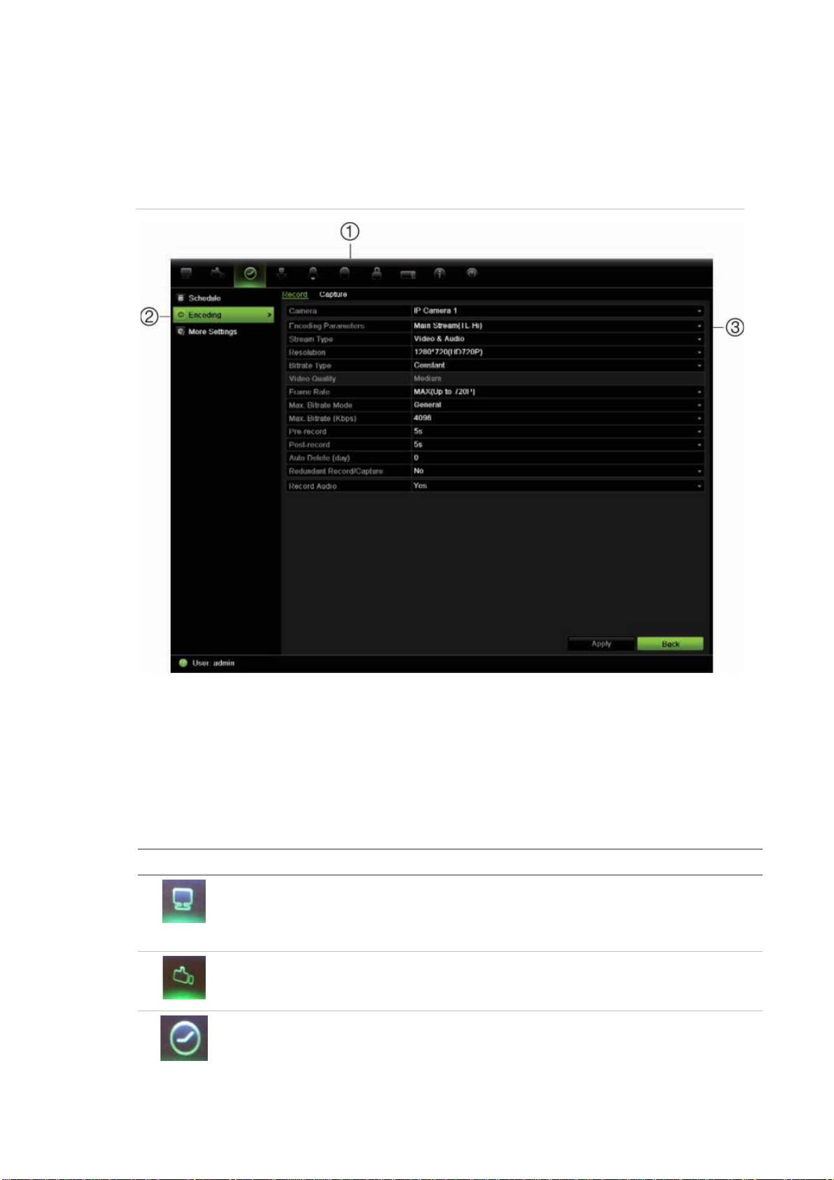
The screen is divided into three sections. The currently selected command icon
and submenu item are highlighted in green. See Figure 9 below.
You must be in live view mode to access the main menu.
Figure 9: Menu structure
1. Menu toolbar: Setup options available for the selected menu function. Move the mouse over
a command icon and click to select it. See Table 4 below for a description of the icons.
2. Submenu panel: Submenus for the selected menu function are displayed. Click an item to
select it.
3. Setup menu: All the details for the selected submenu are displayed. Click a field to make
changes.
Table 4: Description of the menu toolbar icons
Icon Name Description
Configures dis p lay settings including system date and time,
Configures recording settings including recording
audio output, device name, dwell time, schedule, language
and display formats. See “Configuring live view” on page 33
and “Holiday schedules” on page 82.
Configures camera settings including motion detection,
video image adjustments, video loss, and camera title. See
Chapter 14 “Camera settings” on page 111.
schedules, record quality, auto delete mode, and recording
mode. See Chapter 10 “Recording” on page 77.
TruVision NVR 50 User Manual 23
Page 30
3BChapter 4: Operating instructions
Network settings
Alarm settings
PTZ settings
User management
System
Help information
Power manager
Icon Name Description
Configures standard network settings including IP address,
Configures alarm settings including alarm input, relay
Configures PTZ settings including RS-485 settings. See
Configures users, passwords, and access privileges. See
settings Configures system settings including RS-232 settings,
Provides reference information to the various toolbars,
e-mail notifications, DDNS s etup, and ad vanced network
settings. See Chapter 12 “Network settings” on page 97.
output, remote alert, pre-alarm and post-alarm seconds.
See Chapter 11 “Alarm settings” on page 87.
Chapter 6 “Controlling a PTZ cam er a” on page 41.
Chapter 16 “User management” on page 121.
firmware upgrade, hard drive settings, and boot log. See
Chapter 13 “HDD management” on page 105 and
Chapter 15 “NVR management” on page 115.
menus, and keys within the interface.
Provides access to logout, reboot and shutdown options.
See “Turning on and off the NVR” on page 11.
To access the main menu:
1. In live view press the Menu button on the remote control or front panel.
- Or Right-click the mouse and select Menu from the pop-up menu.
The main menu screen appears. The Display screen appears by default.
2. Click the required menu icon to display its submenu options. Modify the
configuration parameters as required.
3. Click Apply to save the settings.
4. Click Back to return to live view.
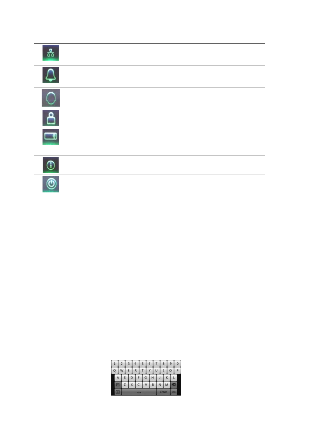
Using the soft keyboard
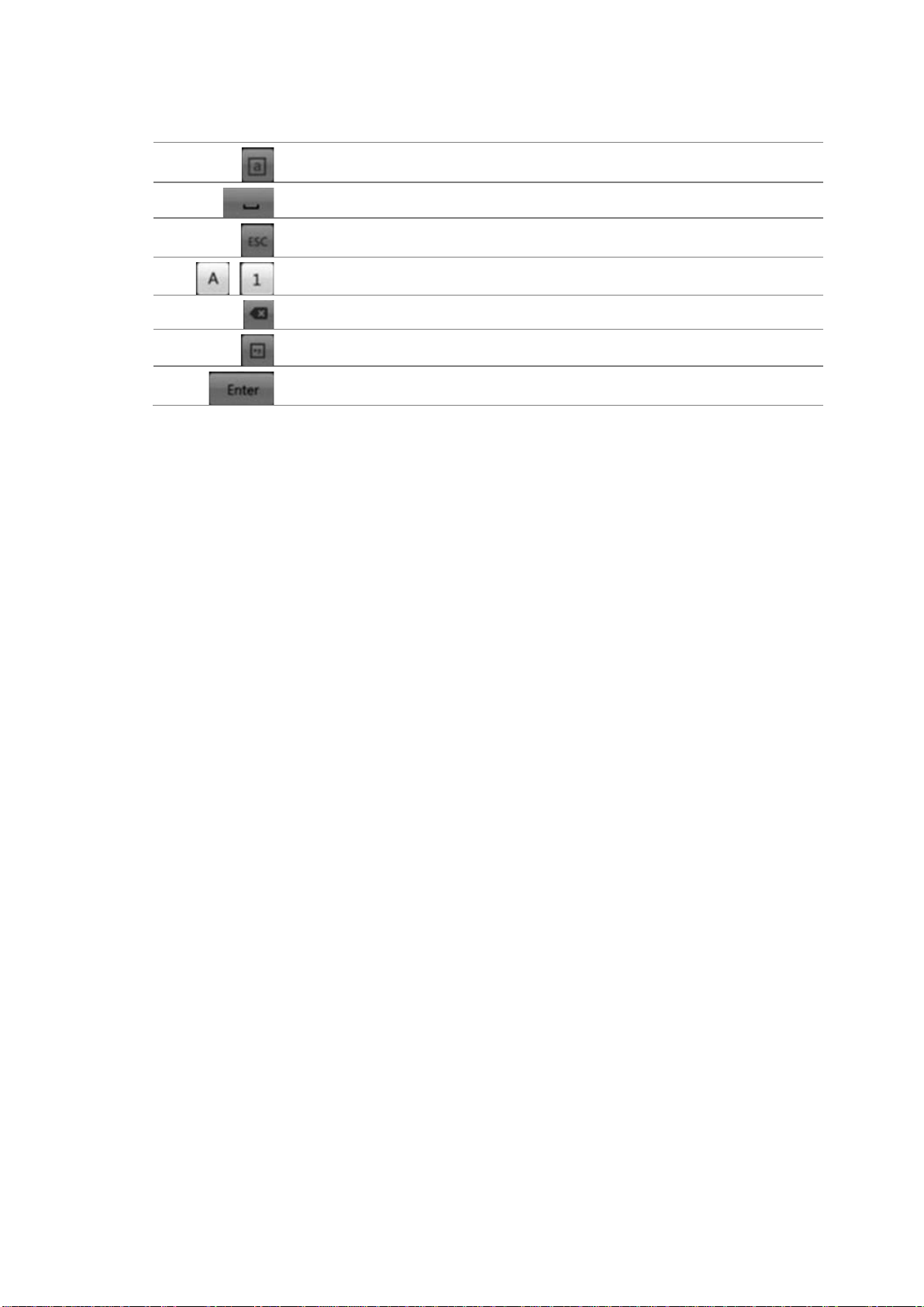
A keyboard will appear on-screen when you need to enter characters in a screen
option. Click a key to input that character.
Figure 10: The soft keyboard
24 TruVision NVR 50 User Manual
Page 31
3BChapter 4: Operating instructions
Switch to
Space
Exit the soft keyboard
Alphanumeric characters
Backspace
Symbols
Confirm selection
Description of the keys in the virtual keyboard:
lowercase/uppercase
Exiting the main menu
Press the Menu button on the front panel to exit the current menu screen and
return to live view or click Back in a main menu.
TruVision NVR 50 User Manual 25
Page 32

3BChapter 4: Operating instructions
26 TruVision NVR 50 User Manual
Page 33
Icon
Chapter 5
Live view
Description of live view
Live view mode is the normal operating mode of the unit where you watch live
images from the cameras. The TVN 50 automatically enters into live view mode
once powered up. On the viewer, you can see the current date and time, camera
name, and whether a recording is in progress.
Status information
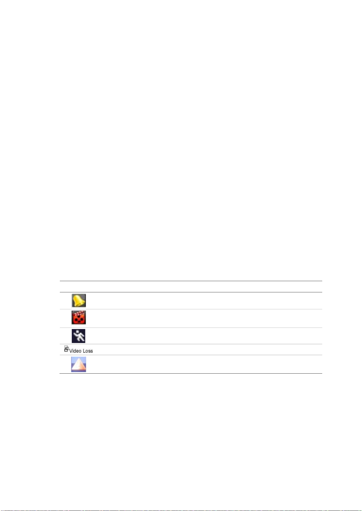
Information on the system and camera status is displayed as icons on the main
and spot monitors. The camera status icons are shown for each camera. Each
icon represents information on a specific item. These icons include:
Table 5: Description of the on-screen status icons
Description
Indicates a sensor alarm.
Indicates recording (such as manual recording, motion detection or alarmtriggered recording).
Indicates a motion detection event.
Indicates a video loss event.
Indicates alarm and system notifications. Clicking the icon opens a screen that
lists the alarms and notifications.
More than one icon can be displayed at the same time.
The system status is displayed on the front panel by the status LEDs.
Video output
The TVN 50 can be connected to up to two monitors. However, only one monitor
can be controlled at a time.
TruVision NVR 50 User Manual 27
Page 34
4BChapter 5: Live view
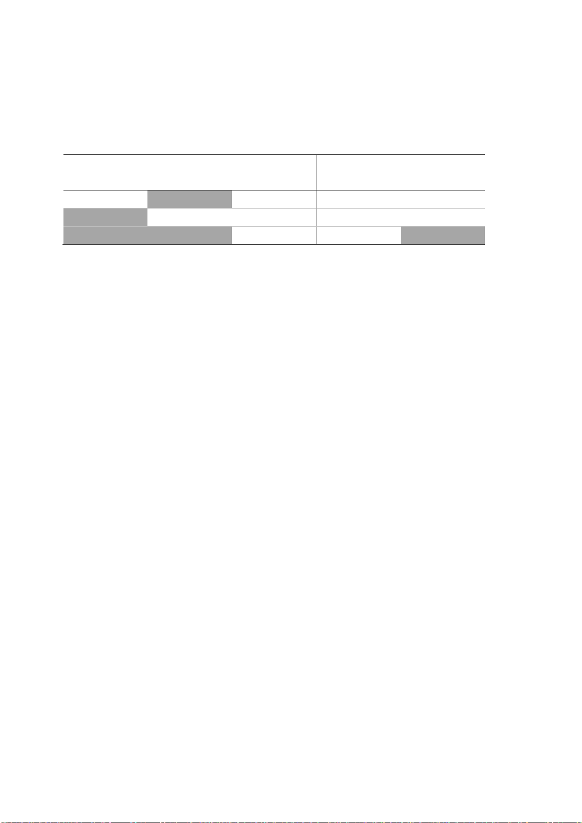
The NVR automatically checks the monitor outputs used. If more than one
monitor is connected, it then defines which monitor is the main one and which is
the auxiliary. The priority level for main and spot outputs is HDMI > VGA >
CVBS. See Table 6 below.
Table 6: Monitor output priority level
Monitor output in use Priority level
HDMI VGA CVBS Main monitor Spot monitor
X X HDMI CVBS
X X VGA CVBS
X CVBS
To select the video output of the main monitor:
1. Click the Display Mode Settings icon in the menu toolbar.
2. Select Layout > General.
3. From Video Output Interface, select which monitor will be the main monitor:
HDMI (depends on NVR model), VGA, main CVBS, or spot output. VGA is
default, if connected.
To control a monitor:
On the front panel press button A to select the main monitor. Press button B
to select the spot monitor.
Audio output
The HDMI monitor connector on the back panel outputs both video and audio
signals. There is an audio output on the back panel for speakers.
Controlling live vie w mode
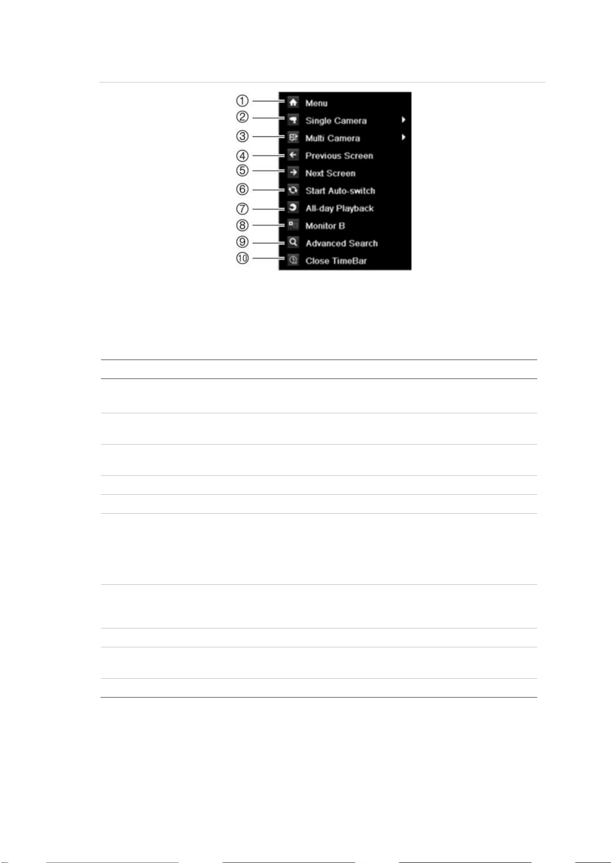
Many features of the live view mode can be quickly accessed by placing the
cursor on a live image and clicking the right-button of the mouse. The mouse
menu appears (see Figure 11 on page 29).
28 TruVision NVR 50 User Manual
Page 35
4BChapter 5: Live view
Item
1.
2.
3.
4.
5.
6.
Menu > Display Mode Settings > Layout > Dwell Time
7.
8.
9.
10.
Figure 11: The mouse menu for the main monitor
The list of commands available depends on which monitor is active; main or spot
(monitor B). See Table 7 below. The default settings of these commands are
provided in Appendix G, “Default menu settings” on page 147.
Table 7: Mouse menu for monitor A (main monitor)
Name Description
Menu Enter the Main menu.
This option is not available from monitor B.
Single camera Switch to a full-screen view for the selected camera from
the dropdown list.
Multi camera Switch between the different multiview options from the
dropdown list.
Previous screen Displays the previous camera.
Next screen Displays the next camera.
Start auto-switch Turn on sequence mode. The screen automatically
sequences between cameras. See “Viewing in multiview”
on page 30.
Go to
to set up.
All-day playback Playback the recorded video of the selected day from the
selected camera. The current day is selected by default.
See “All-day playback” on page 52 for more information.
Monitor B Switch between monitors A (main) and B (spot).
Advanced search Enter the advanced video search menu. See “Searching
recorded video” on page 53 for more information.
Close timebar Open/close the time bar.
Note: When the monitor B is active, the main monitor commands are
unavailable.
TruVision NVR 50 User Manual 29
Page 36

4BChapter 5: Live view
Item
1.
2.
3.
4.
5.
6.
Table 8: Mouse menu for monitor B (spot monitor)
Name Description
Single camera Switch to a full-screen view for the selected camera from
the dropdown list.
Multi camera Switch between the different multiview options from the
dropdown list.
Previous screen Displays the previous camera.
Next Screen Displays the next camera.
All-day playback Playback the recorded video of the selected day from
selected cameras. See “All-day playback” on page 52 for
more information.
Monitor A Switch between monitors A (main) and B (spot).
Multiview format
The NVR has full screen display format as well as five multiview formats.
Viewing in full screen
Press the numeric button on the front panel to switch to the corresponding
camera display. For example, press button 10 to view camera 10.
Right-click the mouse and select Single Camera from the menu. Sel ec t the
camera required from the list.
Viewing in multiview
A video tile is any cell in a multiview display. A camera image can only be shown
in one video tile at a time. The TVN 50 has five multiview display formats
available as well as full screen. See Figure 12 below.
To change the multiview display that appears by default, go to the Display menu.
See “Changing the camera sequence” on page 35 for more information.
Figure 12: Multiview display formats
30 TruVision NVR 50 User Manual
Page 37

4BChapter 5: Live view
To select a multiview format:
1. Press the Display button on the front panel to cycle through different display
formats.
You can also right-click the mouse and select Multi Camera from the menu.
Select the desired multiview display layout.
Sequencing cameras
The sequencing feature allows a camera to be displayed briefly on screen,
before advancing to the next camera in the sequence list.
The default sequence displays each camera in numerical order. However, each
camera on the main and spot monitors can have a pre-programmed dwell time
and sequence order. See “Changing the camera sequence” on page 35 for more
information.
Note: Dwell time must not be set to zero for sequencing to function.
Sequencing live view mode using the front panel:
1. Select the camera where you want to start sequencing.
2. Press the Seq button on the front panel to start sequencing.
3. Press the Seq button again to stop the sequencing.
Sequencing live view mode using the mouse:
1. Select the camera where you want to start sequencing.
2. Right-click the mouse and select Start auto-switch to start the sequencing.
3. Right-click the mouse and select Stop auto-switch to stop the sequencing.
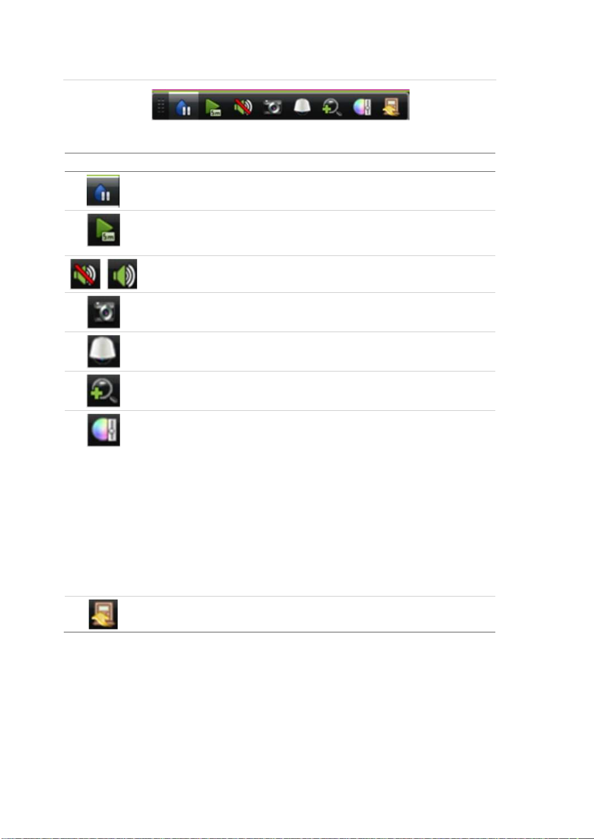
Accessing frequently used commands
The quick access toolbar in live view lets you quickly access regularly used
commands. Position the cursor over a video image and left-click the mouse. The
toolbar appears (see Figure 13 on page 32).
TruVision NVR 50 User Manual 31
Page 38
4BChapter 5: Live view
Figure 13: Quick access toolbar
Table 9: Description of the quick access toolbar icons
Icon Description
Freeze: Freeze the live image of the selected camera. Although the image
pauses, time and date information does not. The system clock continues to run.
Instant playback: Playback the recorded video from the last five minutes. If no
recording is found, then there was no recording made in the last five minutes.
Click the icon and select the desired camera. Click OK.
Audio: Enable/Disable audio output. The audio option must already have been
setup in the Display menu.
Quick snapshot: Capture a snapshot of a video image. The image is saved on
the unit.
PTZ control: Enter PTZ control mode.
Digital zoom: Enter digital zoom. See “Digital zoom” below for further
information.
Image settings: Enter the image settings menu to modify the image lighting
levels. There are two options:
Preset Mode: These are preconfigured image lighting levels. Select one of the
four options depending on current lighting conditions:
- Standard: Use in standard lighting situations.
- Indoor: Use indoors.
- D im Light: Use when the light level is low.
- Outdoor: Use when outdoors. The contrast and saturation values are
high.
Customize: Modify brightness, contrast, saturation, and hue values.
Restore: Restore image settings to prev ious va lues .
These settings can also be modified from the Camera>Image menu (see page
“Adjusting video image settings” on page 113.
Close toolbar: Close the shortcut toolbar.
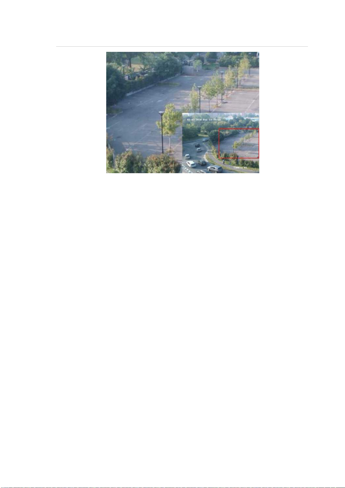
Digital zoom
You can easily zoom in or out of a camera image in live view mode and playback
using the digital zoom command. The zoo m command magnifies the camer a
image four times. See Figure 14 on page 33.
32 TruVision NVR 50 User Manual
Page 39
4BChapter 5: Live view
Figure 14: Digital zoom screen
To quickly zoom in/out on a camera image:
1. Select the camera you wish to use.
2. Left-click the mouse and select the digital zoom icon, or on the front panel
press the Zoom+ button. The digital view screen appears.
3. Left-click the mouse and drag the red square to the area of interest, or move
the joystick on the front panel to position the red square. The selected area is
magnified.
4. To exit digital zoom right-click the mouse or press the Zoom— button on the
front panel.
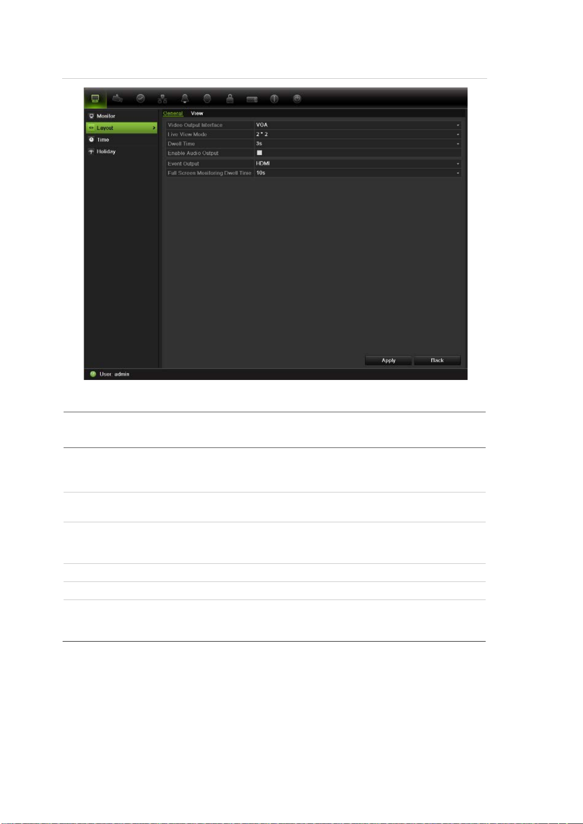
Configuring live view
The setup of live view can be modified from the main menu to suit different
needs, such as the different monitors, multiview layout, and dwell time options.
You can also enable audio output.
TruVision NVR 50 User Manual 33
Page 40
4BChapter 5: Live view
Submenu name
General tab
Video output interface
Live view mode
Dwell time
Enable audio out
Even
Full screen monitoring
dwell time
Figure 15: Layout screen
Table 10: Description of the layout screen
Description
Select which monitor will be the main monitor: HDMI (depends on
NVR model), VGA, main CVBS and spot output.
Default is VGA, if connected.
Select which multiview layout will be default in live view mode. Default
is 4x4 multiview layout.
Set the length of time for which a camera image is displayed on the
selected monitor before moving to the next camera during
sequencing. Default is off (“No switch”).
Check the box to enable/disable audio output.
t output Designates which monitor will be the output to show the event.
Set the length of time for which an alarm event appears on the output
monitor before moving to the next camera during sequencing. Default
is 10 seconds.
To set up the display options:
1. Click the Display Mode Settings icon in the menu toolbar.
2. Select Layout > General.
3. Specify the desired settings for each of the menu options.
34 TruVision NVR 50 User Manual
Page 41
4BChapter 5: Live view
4. Click Apply to save the settings.
5. Click Back to return to live view .
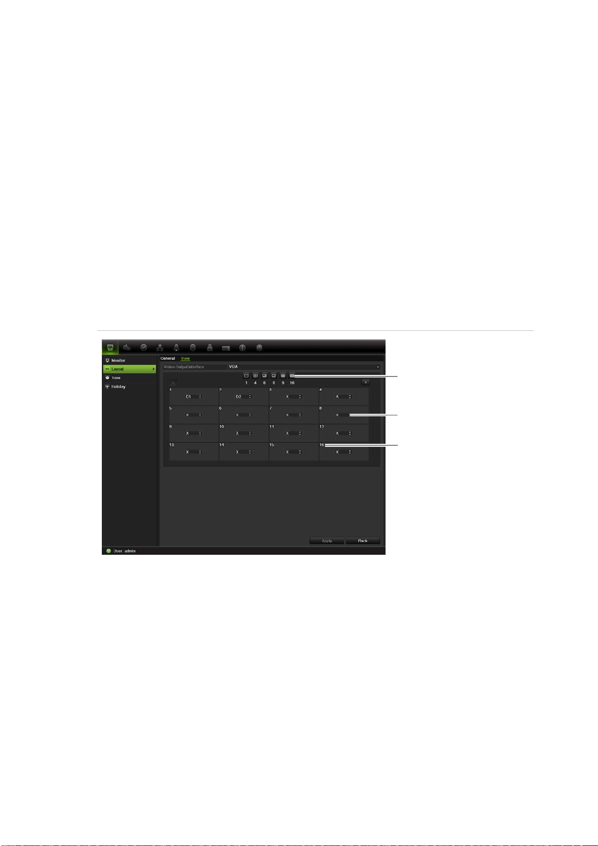
Changing the camera sequence
The cameras are sequenced in numeric order by default. You can change the
sequence order of the cameras for all moni tors.
You can switch the channel of a camera with that of another camera in the
system. This lets you, for example, have the images of camera 1 appear on
channel 10, and the images of camera 10 appear on channel 1. This feature is
useful when you want to watch the sequence of images from specific cameras so
that they are next to each other on-screen.
See Figure 16 below. Each video tile displays both the order of the camera in the
sequence and the camera number.
Figure 16: Camera layout and sequence screen
Multiview layout selection
bar
Camera order in the
sequence
Camera number selection
To set the camera sequencing:
1. Click the Display Mode Settings icon in the menu toolbar.
2. Select Layout > View.
3. From Video Output Interfac e, select the desired monitor from the drop-down
list.
4. From the multiview layout selection bar, select the desired multiview layout.
5. Select the video tile of the camera whose order you want to change. The
selected tile is highlighted green.
6. In the selected tile, select the new camera sequence order by scrolling the
through the list of available camera numbers.
TruVision NVR 50 User Manual 35
Page 42
4BChapter 5: Live view
Option
Language
Device name
Device address
Zone ID
Note: “X” means that the camera is not displayed.
7. Click Apply to save the settings.
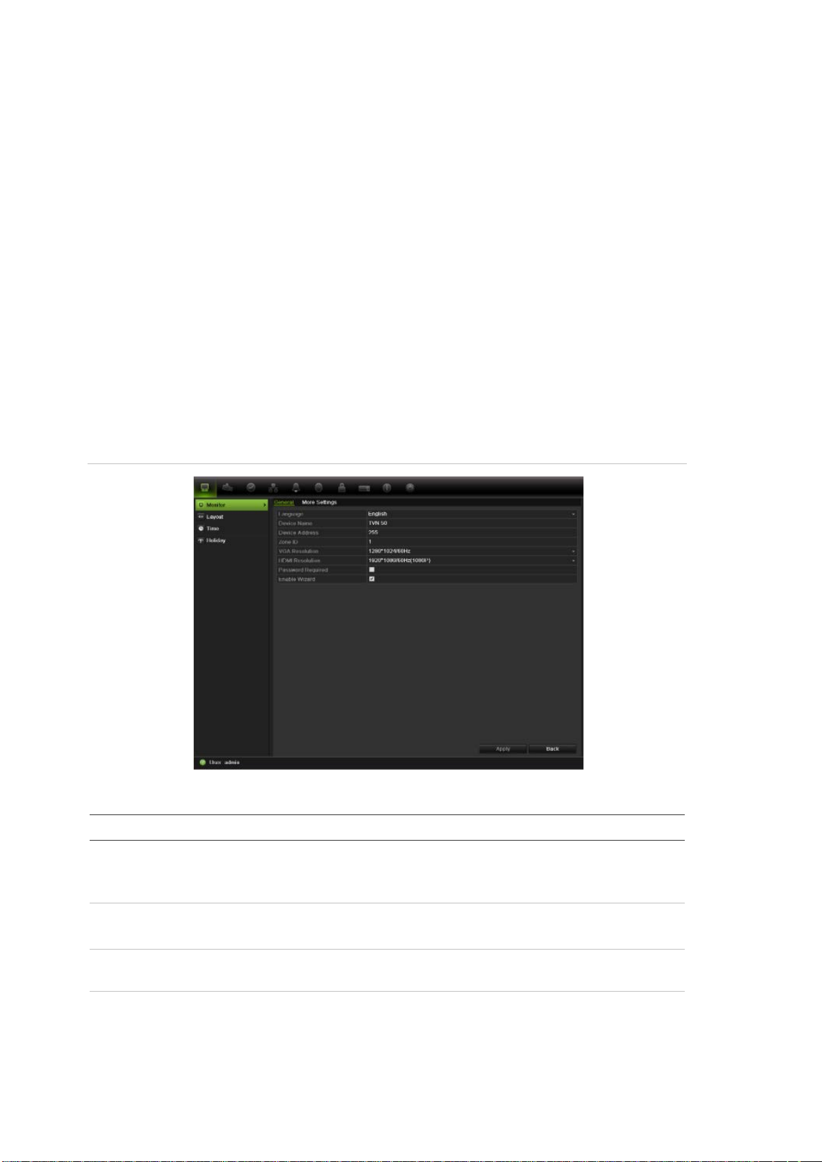
8. Click Back to return to live view.
General settings
Use this screen to configure the monitor image, GUI language, login password
requirement, monitor resolution as well as to configure the NVR name and
address. See Figure 17 below.
The TVN 50 can support NTSC or PAL video output. The video format is auto
detected.
The changes are immediately implemented once Apply is clicked to save the
settings.
Figure 17: Monitor setup screen: General Settings
Table 11: Description of the Monitor setup screen: General Settings
Description
Change the language of the system.
Select the desired language from the drop-down list and cl ic k
Apply. The language displayed changes immediately.
Define the NVR name. The default name is TVN50.
Click the edit box and enter the new name from the soft keyboard.
The device number to use for the NVR when programming the
remote control or keypad. The default value is 255.
Each TVN in a daisy chain must have a unique zone ID so that it
can be controlled by a KTD-405.
The default value is 1.
36 TruVision NVR 50 User Manual
Page 43
4BChapter 5: Live view
Option
VGA resolution
HDMI resolution
Password required
Enable wizard
Option
Monitor standard
Output mode
Monitor brightness
Event hint
Time
Enable TimeBar
Menu timeout
Mouse pointer speed
Description
Define the VGA resolution.
Select one of the options from the drop-down list and click Apply.
The selected resolution must be the same as that of the monitor.
Define the HDMI resolution.
Select one of the options from the drop-down list and click Apply.
The selected resolution must be the same as that of the monitor.
Define whether a login password is required.
Check the box to enable/disable and click Apply.
Define whether the wizard tool starts when the NVR is turned on.
Check the box to enable/disable and click Apply.
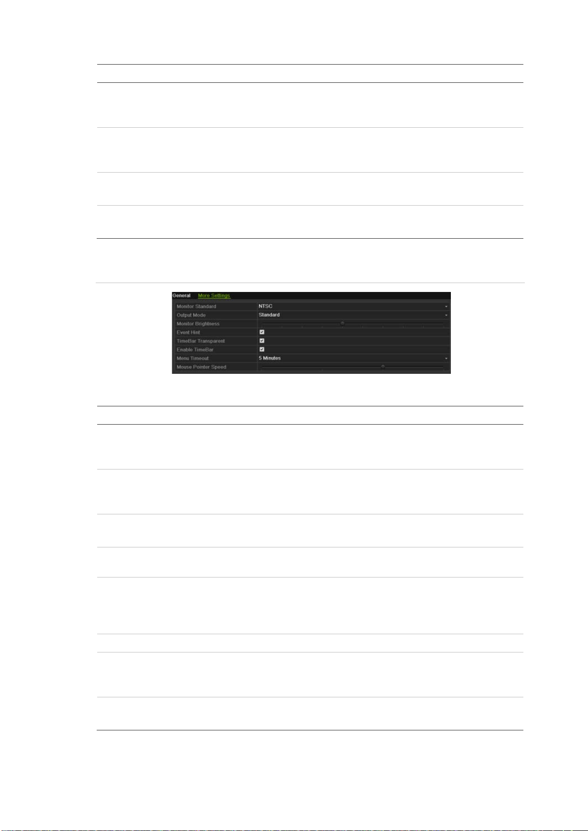
Figure 18: Monitor setup screen: More Settings
Table 12: Description of the Monitor setup screen: More Settings
Description
The video standard used is auto detected but can be manually
changed.
Modify the video standard used to PAL or NTSC and click Apply.
Define the desired output mode.
Select one of the options from the drop-do wn lis t: Stan dard, Br ig ht,
Soft, or Vivid.
Modify the video output brightness.
Adjust the scroll bar point to the desired level and click Apply.
Define whether the status icons appear on screen. See “Status
information” on page 27 for more information.
Bar transparent Modify the transparency of the menus on-screen relative to the
background to make the menu screens easier to read or less
prominent on-screen. Default is non-transparent.
Select one of the options from the check box.
Enable/Disable Time Bar in live view mode.
Define the time in minutes after which the menu screen reverts to
live view mode.
Select a time from the drop-down list and click Apply.
Modify the speed of the mouse pointer.
Adjust the scroll bar point to the desired level and click Apply.
TruVision NVR 50 User Manual 37
Page 44
4BChapter 5: Live view
Option
Time zone
Date format
Time format
Display week
System date
System time
Configuring time and date
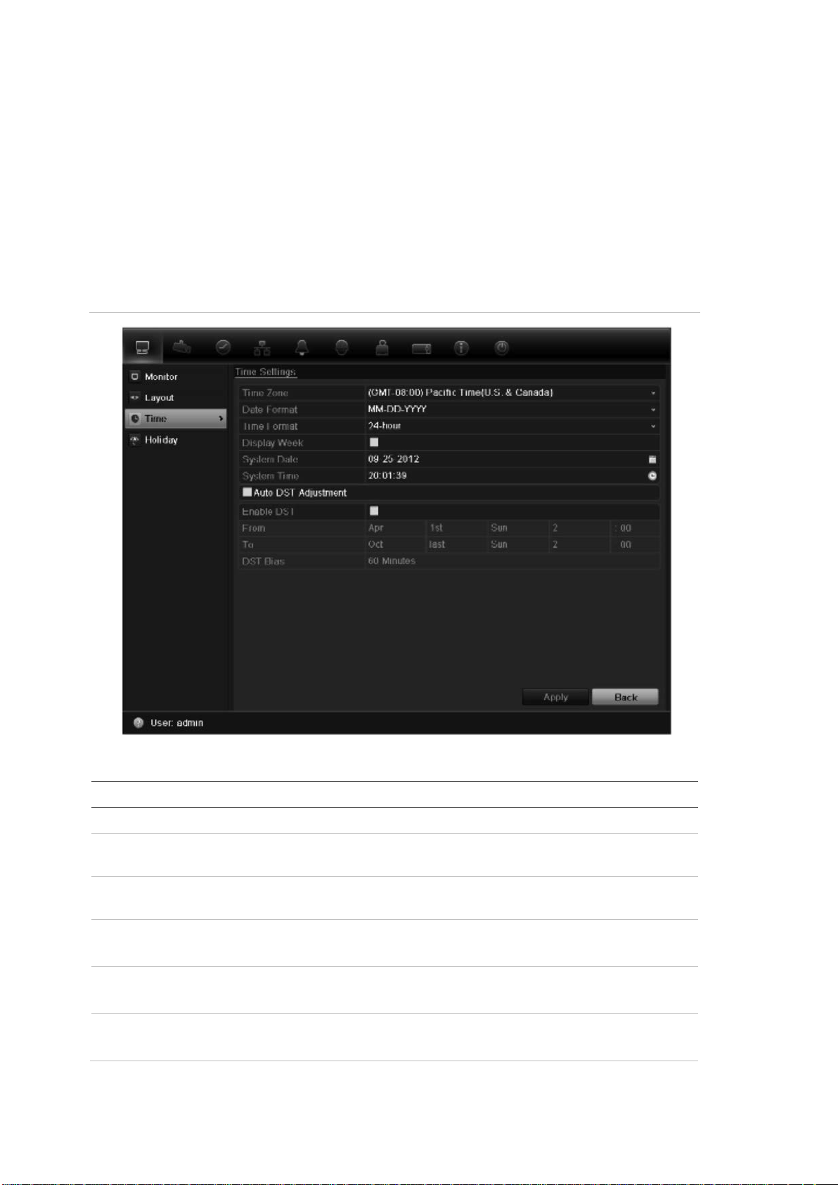
You can set up the date and time that will appear on-screen. It is not included in
recordings. This time and date display is separate from the embedded one that
appears for each camera (see “Configuring the camera OSD settings” on page
111 for more information on embedded camera time and date).
The start and end time of daylight savings time (DST) in the year can also be set.
DST is deactivated by default. See Figure 19 below for the Time settings screen.
Figure 19: Time and date settings screen
Table 13: Description of the time and date settings screen
Description
Select the time zone of the NVR from the drop-down list.
Select the date format from the drop-down list. Default format is DD-
MM-YYYY.
Select the time format from the drop-down list. Default format is 24-
hour format.
Displ a y the da y of the week in the monitor time bar.
Check the box to enable/disable. Default format is Disable.
Define the system date.
Default date is the current date.
Define the system time.
Default time is the current time.
38 TruVision NVR 50 User Manual
Page 45

4BChapter 5: Live view
Option
Auto DST adjustment
Enable DST
From
To
DST bias
Description
Define DST is automatically. It depends on the time zone selected.
Default format is Disable
Manually define DST. If this option is selected, the Auto DST
adjustment option is disabled.
Default format is Disable.
Click the check box to enable or disable daylight savings time
(DST).
Enter the start date and time for daylight savings.
Enter the end date and time for daylight savings.
Set the amount of time to move DST forward from the standard
time.
Default is 60 minutes.
To set up the system time and date:
1. Click the Display Mode Settings icon in the menu toolbar.
2. Select Time. Modify the required settings.
3. Click the Apply button to immediately implement the changes.
TruVision NVR 50 User Manual 39
Page 46

Page 47

Chapter 6
Controlling a PTZ camera
You can control PTZ dome cameras using the buttons on the front panel, the
keypad, and IR remote control as well as using the PTZ control panel accessed
with the mouse. Access to PTZ commands may require a password.
A detailed list of the PTZ commands available for many different camera
protocols is available in Appendix F on page 147.
Configuring PTZ settings
Use the PTZ Settings menu to configure the PTZ dome cameras. Each camera
must be set up individually. Cameras must be configured be for e they can be
used.
Ensure that the PTZ dome ca meras ar e correctly connected to the RS-485 port
on the back panel.
Note: If a camera does not work correctly after configuring the NVR, check the
parameters entered.
To configure PTZ dome camera settings:
1. Click the PTZ Settings icon in the menu toolbar.
2. Click General and select the PTZ dome camera to be configured from the
drop-down camera list.
3. Select the baud rate, data bit , st op bit , par it y , flow control, PTZ protocol and
address for the camera. See Appendix G, “Default menu settings”, on page
147 for the default values.
Note: It is important to ensure that the settings correspond with those used in
the PTZ camera.
4. Click Copy to copy the settings to another camera, if required.
5. Click Apply to save the settings.
TruVision NVR 50 User Manual 41
Page 48
5BChapter 6: Controlling a PTZ camera
Item
1.
2.
3.
4.
Calling up presets, tours and shadow tours
When in live view you can quickly call up the list of existing presets, preset tours
and shadow tours by using the front panel, remote control, mouse and keypad.
Front panel Press the joystick to Enter. PTZ control panel appears.
Mouse Left-click the mouse on the desired camera image. The quick access
toolbar appears. Click the PTZ control icon to enter PTZ mode. The PTZ
control panel appears.
Remote control Press the OK button. The PTZ control panel appears.
Keypad Press the Enter button on the keypad. For further information, see Error!
Not a valid result for table. “KTD-405 keypad” on page 135.
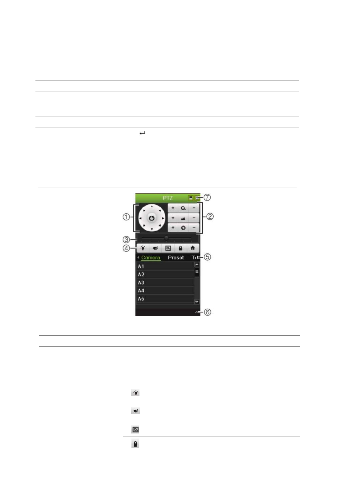
If the display was in multiview format, it changes to full screen format for the
selected camera. See Figure 20 below for a description of the PTZ control panel.
Figure 20: PTZ control panel
Table 14: Description of the PTZ control panel
Name Description
Directional pad/auto-
scan buttons
Zoom, focus and iris Adjusts zoom, focus and iris.
PTZ movement Adjusts the speed of PTZ movement.
Toolbar
42 TruVision NVR 50 User Manual
Controls the movements and directions of the PTZ. Center button
is used to start auto-pan by the PTZ dome camera.
Turns on/off camera light. This command is not
supported on all PTZ cameras.
Turns on/off camera wiper. This command is not
supported on all PTZ cameras.
Zoom area.
Centers the PTZ dome camera image. This command is
not supported on all PTZ dome cameras.
Page 49
5BChapter 6: Controlling a PTZ camera
Item
5.
6.
7.
Item
1
2
3
Name Description
Select PTZ command Displays the desired function from the scroll bar: camera, preset,
preset tour or shadow tour.
Open/close menu Opens/closes the PTZ command section of the PTZ control
panel.
Exit Exits the PTZ control panel.
Jumps to the home position.
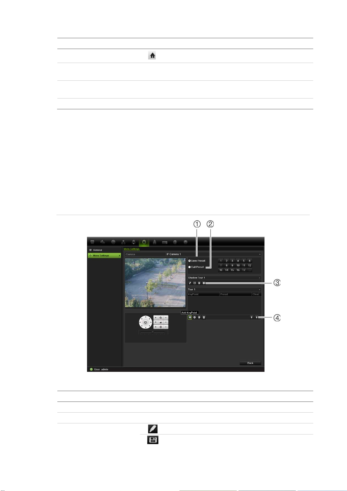
Setting and calling up presets
Presets are previously defined locations of a PTZ dome camera. It allows you to
quickly move the PTZ dome camera to a desired position. They are config ur ed
and modified from the PTZ configuration window (see Figure 21 below).
Note: The PTZ dome camera used must be able to support a preset command.
See Appendix F on page 147 for the complete list of PTZ commands available by
camera protocol.
Figure 21: PTZ configuration window
Table 15: Description of the PTZ configuration window
Name Description
. Save preset Saves preset.
. Call preset Calls up pre-existing pr es et .
. Shadow tour toolbar
TruVision NVR 50 User Manual 43
Starts recording the shadow tour.
Saves the shadow tour.
Page 50

5BChapter 6: Controlling a PTZ camera
Item
4
Name Description
. Preset tour toolbar
Starts the selected shadow tour.
Stops the selected shadow tour.
Adds a step to a selected preset tour.
Starts the selected preset tour.
Stops the selected preset tour.
Deletes all the preset tour steps.
Scroll up the list.
Scroll down the list.
To set up a preset:
1. Click the PTZ Settings icon on the menu toolbar and select More Settings.
2. Use the directional, zoom, focus and iris buttons to position the camera in the
desired preset locatio n .
3. Check Save Preset and enter a preset number. The preset is enabled and
stored in the camera.
If the desired preset number is larger than the 17 numbers listed, click […].
The Preset screen appears. Select a preset number from the dropdown list
and click the OK button to save changes.
Note: Presets can be overwritten.
4. Click Back to return to live view.
To call up a preset:
• PTZ control panel:
1. In live view left-click the mouse and select the PTZ control icon in the quick
access toolbar. The PTZ control panel appears. Select the desired camera
from the toolbar.
– Or –
On the front panel, select the desired camera and press Enter on the joystick
to call up the quick access toolbar. The PTZ control panel appears.
2. Scroll the toolbar to Preset and doubl e-click the desired preset from the list.
The camera immediately jumps to the preset position.
• Menu toolbar:
1. Click the PTZ Settings icon on the menu toolbar and select More Settings.
The PTZ configuration window appears.
2. Check Call Preset and enter the preset number to call up. The camera
immediately moves to that preset position.
3. Click Back to return to live view.
44 TruVision NVR 50 User Manual
Page 51
5BChapter 6: Controlling a PTZ camera
Setting and calling up preset tours
Preset tours move a PTZ dome camera to different steps (called “Keypoint” in the
interface). The camera stays at a step for a set dwell time before moving on to
the next step. The steps are defined by presets (see “Setting and calling up
presets” on page 43.)
Each preset tour consists of steps. A step consists of a step number, a dwell
time, and a speed.
The step number is the order the camera will follow while cycling through the
preset tour. The dwell time is the length of time for which a camera stays at a
step before moving to the next one. The speed is the rate at which the camera
will move from one key point to the next .
Note: The PTZ dome camera used must be able to support a preset tour
command. See Appendix F on page 147 for the complete list of PTZ commands
available by camera protocol.
To set up a preset tour:
1. Click the PTZ Settings icon on the menu toolbar and select More Settings.
2. Select the preset tour number.
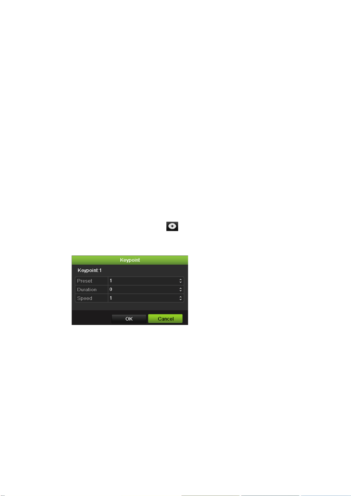
3. In the preset tour toolbar, click to add a step to the preset tour. The
Keypoint window appears. Select the preset number, dwell time and speed of
the step. Click OK to save the settings.
Note: A preset tour should have at least two presets.
4. Repeat step 3 to configure other steps (“Keypoints”) in the preset tour.
TruVision NVR 50 User Manual 45
Page 52
5BChapter 6: Controlling a PTZ camera
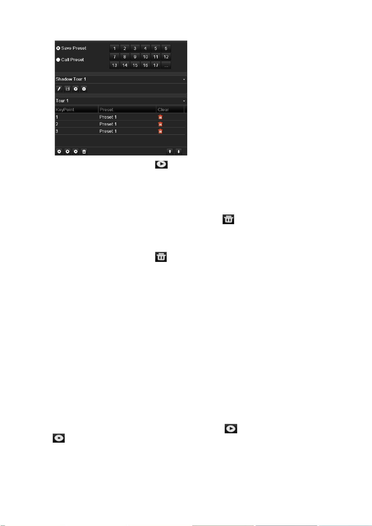
5. In the preset tour toolbar, click to call up the preset tour.
6. Click Back to return to live view.
To delete a preset tour:
1. Click the PTZ Settings icon on the menu toolbar and select More Settings.
2. From the preset list, select a tour number and click to delete the selected
the preset tour.
– Or –
In the preset tour toolbar, click to delete all the preset tours.
3. Click Back to return to live view.
To call up a preset tour:
• PTZ control panel:
1. In live view left-click the mouse and select the PTZ control icon in the quick
access toolbar. The PTZ control panel appears. Select the desired camera
from the toolbar.
– Or –
On the front panel, select the desired camera and press Enter on the joystick
to call up the quick access toolbar. The PTZ control panel appears.
2. Scroll the toolbar to Tour and double-click the desired preset tour from the
list. The camera immediately carries out the preset tour movement.
• Menu toolbar:
1. Click the PTZ Settings icon on the menu toolbar and select More Settings.
2. Select the desired preset tour from the list and click to start the tour. Click
to stop the preset tour.
3. Click Back to return to live view.
46 TruVision NVR 50 User Manual
Page 53

5BChapter 6: Controlling a PTZ camera
Setting and calling up a shadow tour
The shadow tour command remembers the manually-controlled PTZ dome
camera movement track. One shadow tour can be set up.
Note: The PTZ dome camera used must be able to support a shadow tour
command. See Appendix F on page 147 for the complete list of PTZ commands
available by camera protocol.
To set up a shadow tour:
1. Click the PTZ Settings icon on the menu toolbar and select More Settings.
2. Select the shadow tour from the list.
3. To record a new shadow tour, click and use the directional buttons on the
PTZ control panel to move the camera along the desired path.
4. Click to save the shadow tour.
Note: The shadow tour can be overwritten.
5. Click Back to return to live view.
To call up a shadow tour:
• PTZ control panel:
1. In live view left-click the mouse and select the PTZ Control icon in the quick
access toolbar. The PTZ control panel appears. Select the desired camera
from the toolbar.
– Or –
On the front panel, select the desired camera and press Enter on the joystick
to call up the quick access toolbar. The PTZ control panel appears.
2. Scroll the toolbar to Shadow Tour and double-click the shadow tour from the
list. The camera immediately carries out the shadow tour movement.
• Menu toolbar:
1. Click the PTZ Settings icon on the menu toolbar and select More Settings.
2. Select the shadow tour from the list and click to start the tour. Click
to stop the shadow tour.
3. Click Back to return to live view.
TruVision NVR 50 User Manual 47
Page 54

5BChapter 6: Controlling a PTZ camera
48 TruVision NVR 50 User Manual
Page 55

Chapter 7
Playing back a recording
The TVN 50 lets you to quickly locate and play back recorded video. There are
four ways to play back video:
Instant playback of the most recently recorded video
All-day playback of the day’s recorded video
Search the video archives by specific time, date, bookmark, snapshot or
event
Search the system log
The NVR continues to record the live view from a camera while simultaneously
playing back video on that camera display. You must have the access privilege to
play back recordings (see “Customizing a user’s access privileges” on page 122
for more information).
Cameras in multiview mode play back simultaneously. This means, for example,
that it is easy to follow the path of an intruder who has passed in front of several
cameras.
Overview of the playback window
It is easy to manage playback from the playback window.
The playback video can be set up to display a time/date stamp for evidentiary
purposes.
TruVision NVR 50 User Manual 49
Page 56
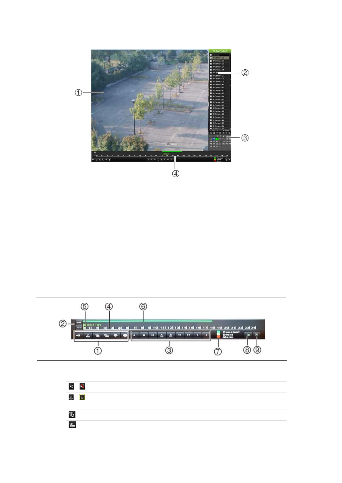
6BChapter 7: Playing back a recording
4. Playback control toolbar. See Figure 23.
Ite
1.
Figure 22: Playback window
1. Playback viewer.
2. Camera panel. Select the cameras for
playback. Move the mouse over the area to
display the list of cameras available.
3. Calendar panel.
Blue: Current date
Green/Yellow/Red: Recordings available
on the NVR.
The playback control toolbar
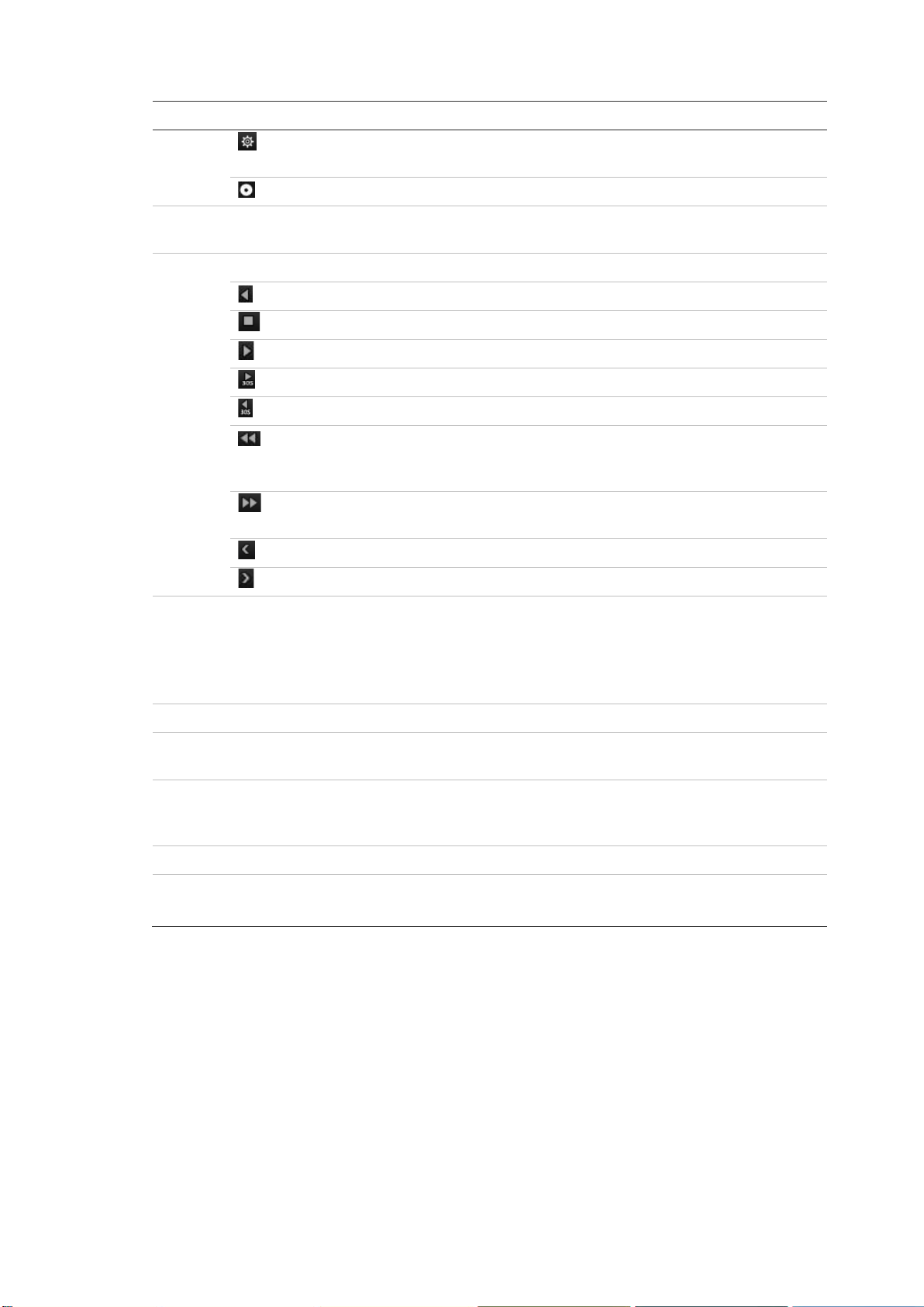
It is easy to manually control playback using the playback control toolbar. See
Figure 23 below.
Note: The control toolbar does not appear for inst ant play bac k.
Figure 23: Playback control toolbar (all-day playback example shown)
m Description
Audio and video control toolbar:
/ Audio on/off.
/ Start/stop a video clip during playback. Sections of a recording can be
saved to an external storage device.
Add default bookmark
Add customized bookmark
50 TruVision NVR 50 User Manual
Page 57
6BChapter 7: Playing back a recording
Ite
2.
3.
4.
5.
6.
7.
8.
9.
m Description
Bookmark management.
Click to see the list of bookmarks and their times.
Archive files
Zoom control: Zoom in and out of the timeline to show the progress bar in greater or
lesser detail.
Playback control toolbar:
Reverse play the recording. Click again to pause.
Stop playback. Timeline jumps back to 00:00 time (midnight).
Play recording.
Fast forward playback by 30 seconds.
Reverse playback by 30 seconds.
Decrease playback speed: Options available are: single frame, 1/8 speed,
¼ speed, ½ speed, normal, X2 speed, X4 speed, X8 speed, maximum
speed.
Increase playback speed. Options available are: single frame, 1/8 speed, ¼
speed, ½ speed, normal, X2 speed, X4 speed, X8 speed, maximum speed.
Previous file/day/event recording.
Play next file/day recording in the search result.
Timeline: Allows you to jump forwards or backwards in time. The timeline moves left
(oldest video) to right (newest video). Click a location on it for where you want
playback to start.
In all-day playback the cursor shows the actual time. In search playback, the cursor
is a ball.
Time bar: Time of actual playback. This is only displayed in all-day playback.
Playback progress bar: This bar displays how far playback of the recording has
progressed. It also indicates the type of recording.
Recording type: Description of the color coding of recording types that appear in the
playback progress bar. Green indicates continuous recording. Red indicates
alarm/event recording. Yellow indicates motion recording.
Hide the playback control toolbar.
For all-day playback mode, quit playback and return to live view.
For playback from search mode, quit playback and return to the search screen.
Instant playback
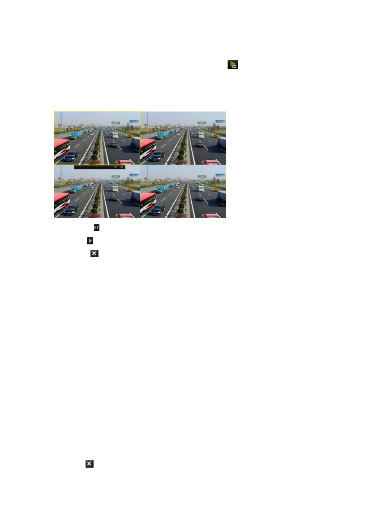
Use the quick access toolbar to quickly replay recorded video from the last five
minutes. This can be useful to review an event that has just happened. Only one
camera at a time can be selected. The default playback period of 5 minutes
cannot be changed.
TruVision NVR 50 User Manual 51
Page 58
6BChapter 7: Playing back a recording
To instantly replay recorded video:
1. In live view mode left-click the mouse on the desired camera image. The
quick access toolbar appears. Click Instant Playback .
2. Select the desired camera from the drop-down list and click OK.
Playback starts immediately. The Instant Playback scroll bar appears under
the selected camera.
3. Click Pause on the toolbar to pause playback.
Click Play to restart playback.
Click Stop to stop playback and return to live view.
All-day playback
Use this option to play back recorded video from the last day. Playback starts at
midnight and runs for the 24-hour period. All-day playback is shown in full screen
view. See Figure 23 on page 50 for a description of the playback control toolbar.
• Using the mouse:
1. In live view mode right-click the mouse on the desired camera image. In the
mouse toolbar click All-day Playback.
The playback screen appears. By default, the camera is in full-screen mode.
2. To select more than one camera for multiview playback or to select playback
from a different day, move the mouse to the right edge of the screen. The
camera list and calendar appear. Check the desired cameras and/or another
day. Up to 32 cameras can be selected.
Playback starts immediately.
Note: A message appears if there are no recordings found during this period.
3. Use the playback control toolbar to manually control playback.
4. Click Exit to return to live view.
52 TruVision NVR 50 User Manual
Page 59

6BChapter 7: Playing back a recording
Search type
Normal
Event
Bookmark
Snapshot
– Or –
Right-click the mouse and click Exit from the mouse menu to return to the
previous screen.
• Using the front panel:
1. Select the camera for playback and press the Play button. Playback from the
selected camera starts immediately.
Note: Multiview playback is only available using the mouse. If live view was
showing multiview, only the camera in the top-left channel on screen will be
played back.
2. To select a different camera for playback, press the numerical button of the
desired camera.
3. Click Live to return to live view.
Searching recorded video
You can easily search and play back recorded videos by time, events,
bookmarks, and video cl i ps.
The Search window has four submenus that allow you to carry out different
searches by theme:
Description
Search all recorded video by cameras, recording type, type of file
protection (locked or unlocked) and time period.
Search only event recorded files. Files can be searched by alarm inputs,
motion detection, or POS/ATM text insertion.
Note: Only motion detection and POS/ATM text insertion that have been
recorded as events will be listed in this search. Motion and text insertion
that is recorded as a non-event can be searched under the Normal
menu.
Search only recorded files with bookmarks.
Search only recorded files with snapshots.
Search results
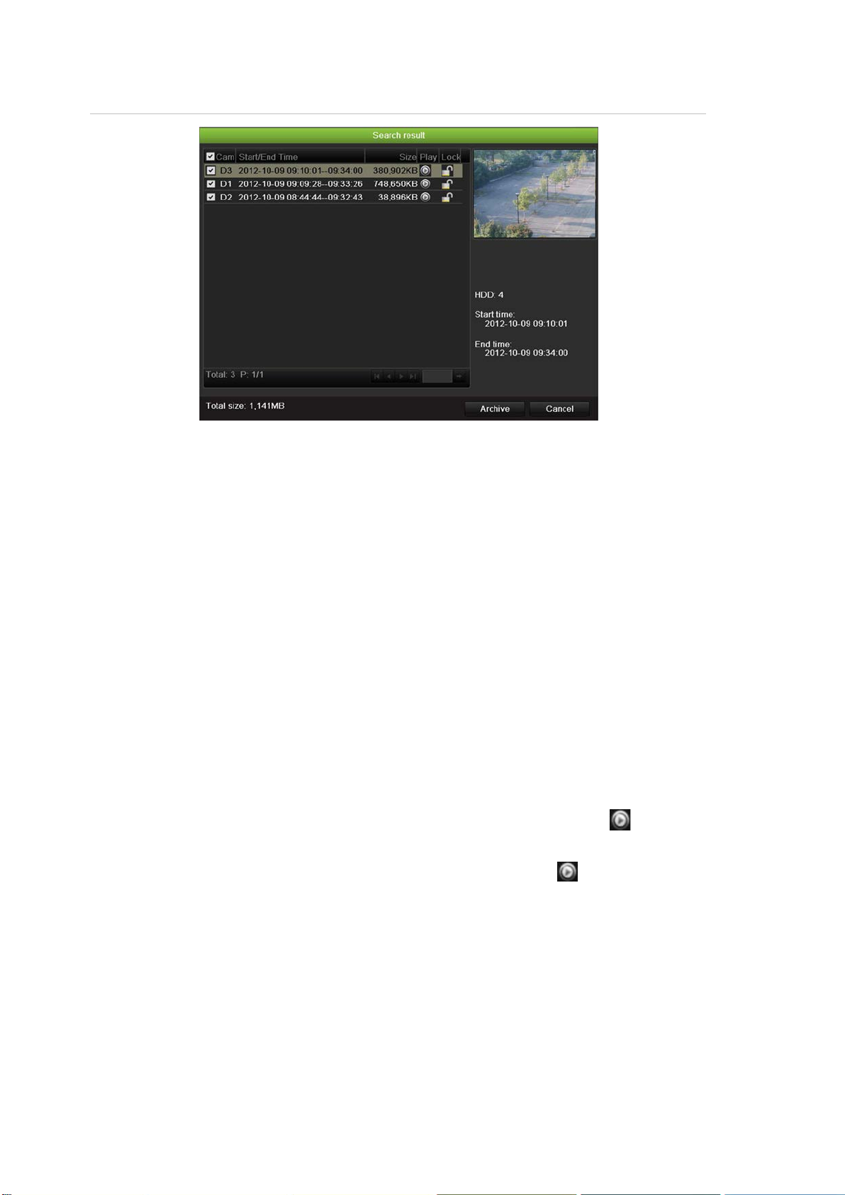
A search will usually produce a list of files, which may extend to several pages.
The files are listed by camera, and then for each camera by date and time. The
latest file is listed first. See Figure 24 on page 54 for an example of a search.
Only one file can be played back at a time.
TruVision NVR 50 User Manual 53
Page 60
6BChapter 7: Playing back a recording
Figure 24: Example of a search result list
Playing back recordings by time and video type
You can search recorded video by time and video type, such as continuous
recordings, motion, text insertion, alarm and all recordings. Video can be played
back simultaneously across several cameras.
To play back search results:
1. In live view mode right-click the mouse and in the mouse menu select
Advanced Search > Normal.
2. Select the desired cameras, record type, file type as well as start and end
time of the recording.
3. Click Search. The list of search results appears.
4. Play back the search results:
If there is only one camera in the search result, click its playback button.
Playback starts.
If there is more than one camera listed, click the playback button of one of
the cameras. In the window that appears, select the cameras you want to play
back simultaneously and click OK. Playback starts.
5. To hide the playback control toolbar during play back, right-click the mouse
and select the Control Panel button in the playback control tool bar . Click
again for the panel to reappear.
6. Use the playback control toolbar to manually control playback.
7. To play back another camera, move the cursor to the right edge of the screen
to display the list of cameras and select the desired camera.
54 TruVision NVR 50 User Manual
Page 61

6BChapter 7: Playing back a recording
8. To do another search:
Click Exit in the playback control toolbar to return to the search results
screen.
- Or Right-click the mouse and select Exit from the list to return to the search
results screen.
- Or Right-click the mouse and select Video Search from the list to return to the
search screen.
Playing back recordings by event
You can search recorded video by event type: motion, alarm input and POS/ATM
text insertion. Video can be played back simultaneously across several cameras.
To play back search results:
1. In live view mode right-click the mouse and in the mouse menu select
Advanced Search > Event.
2. Select the desired event type as well as start and end time of the recording.
3. Select the desired alarm inputs.
4. Click Search. The list of search results appears.
5. Play back the search results:
If there is only one camera in the search result, click its playback button.
Playback starts.
If there is more than one camera listed, click the playback button of one of
the cameras. In the window that appears, select the cameras you want to play
back simultaneously and click OK. Playback starts.
6. To hide the playback control toolbar during playback, right-click the mouse
and select the Control Panel button in the playback control toolbar. Click
again for the panel to reappear.
7. Use the playback control toolbar to manually control playback.
8. To play back another camera, move the cursor to the right edge of the screen
to display the list of cameras and select the desired camera.
9. To do another search:
Click Exit in the playback control toolbar to return to the search results
screen.
- Or -
TruVision NVR 50 User Manual 55
Page 62

6BChapter 7: Playing back a recording
Right-click the mouse and select Exit from the list to return to the search
results screen.
- Or Right-click the mouse and select Video Search from the list to return to the
search screen.
Creating and playing back bookmarked recordings
You can bookmark the important scen es in a rec or ded file for l ater r e ference.
Bookmarks flag the start of a scene. Up to 64 bookmarks can be saved in a video
file. There are two types of bookmarks:
• Default bookmark : All default bookmarks have the same generic name,
“Bookmark”.
• Customized bookmark : The bookmark is given a name for easy
identification. The same name can be used for several bookmarks.
Both types can be searched.
To create a bookmark:
1. Open an all-day playback screen or the playback screen from a search result.
2. In the all-day playback recording, click the timeline bar where you want the
bookmark to be. The green time line jumps to this position. Click the button
for the type of bookmark you want, and enter the bookmark name if required.
In the playback recording from a search, click the scroll bar where you want
the bookmark to be. The scroll bar ball jumps to this position. Click the button
for the type of bookmark you want, and enter the bookmark name if required.
The bookmark is saved.
3. Click the bookmark management button to see the list of bookmarks
saved. The name of a bookmark can be edited. The bookmark can also be
deleted.
To play back a bookmark:
1. In live view mode right-click the mouse and select Advanced Search >
Bookmark in the mouse menu.
2. Select the desired cameras as well as start and end time of the recording to
be searched. Also select the type of bookmark to be searched.
If searching for customized bookmarks, enter a keyword from the bookmark
name.
Click Search. The list of bookmarks appears.
3. Select a bookmark and do one of the following:
56 TruVision NVR 50 User Manual
Page 63

6BChapter 7: Playing back a recording
Click the Edit button to edit a bookmark’s name.
Click the Delete button to delete a bookmark.
- Or Click the Play button to play back a bookmark.
4. When finished, click Exit.
Slideshow of snapshots
You can search video snapshots. See “Accessing frequently used commands” on
page 31 on how to create snapshots.
To play back search results:
1. In live view mode right-click the mouse and in the pop-up menu select
Advanced Search > Picture.
2. Select the desired cameras as well as start and end time of the recording to
be searched.
3. Click Search. The list of snapshots appear s .
4. Select a snapshot to see it in the thumbnail window. Click its Play button
to see it in full-screen mode.
5. When in full-screen mode, move the cursor to the right edge of the screen to
see the complete list of snapshots found in the search. Click their Play
buttons to see them in full-screen mod e.
6. To see a slideshow of all the snapshots found, click the or buttons on
the snapshot toolbar to sequence forwards or backwards through the shots.
7. To do another search:
Click Exit in the snapshot toolbar to return to the search results screen.
- Or Right-click the mouse and select Exit from the list to return to the search
results screen.
- Or Right-click the mouse and select Picture from the list to return to the search
screen.
Playing back recordings from the system log
You can also playback recordings from the system log. The system log provides
a much wider range of options for playback than Advanced Search, which deals
with video detection and alarms only.
TruVision NVR 50 User Manual 57
Page 64
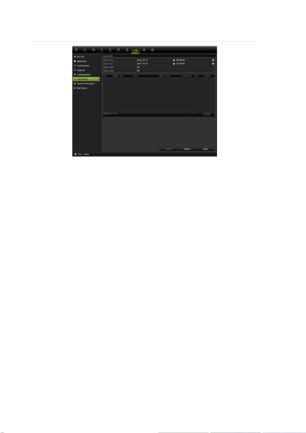
6BChapter 7: Playing back a recording
Figure 25: View log screen
To play back video from the system log:
1. Click System Settings > Log Search in the menu toolbar.
2. Select the search start and end times.
3. Under Major Type and Minor Type, select an option from the dr op-down list.
The minor type list of options available depends on the option selected under
major type.
4. Click the Search button. A list of results appears.
5. Select a file and click:
- Details: Displays informa tion on the log or recording. For a recording, it lists
such information as start time, type of information, camera number, and gives
a description on the types of events recorded and when record time was
stopped.
- Play: Click to start playback of the selected recording.
- Export: Click to archive the selected file to a USB device. The export screen
appears.
- Back: Click to return to the previous screen.
Playing back frame-by-frame
You can easily play back a selected video at different speeds. This allows you to
carefully examine an event frame-by-frame as it happens.
The current frame rate is shown on the right of the playback control toolbar.
58 TruVision NVR 50 User Manual
Page 65

6BChapter 7: Playing back a recording
To play back frame-by-frame:
• Using a mouse:
1. In playback mode click the Speed Down and Speed up buttons in the
playback control toolbar until the speed changes to si ng l e frame.
2. Click the Pause button to advance the video frame by frame.
• Using the front panel:
1. In playback mode move the joystick to left and right to scroll down and up
through the speed changes until single frame.
2. Press Enter with the joystick to advance the video frame by frame.
3. Press the Play button to continue playback at normal speed.
Digital zoom in playback
You can easily zoom in on an image during playback to see it in greater detail.
To digitally zoom-in during playback:
1. In playback mode right-click the mouse and click Digital Zoom in the pop-up
menu. The playback control toolbar disappears.
2. Click the screen with the cursor.
The image zooms in and the digital view screen appears.
3. Left-click the mouse and drag the red square to the area of interest, or move
the joystick on the front panel to position the red square. The selected area is
magnified.
4. Right-click the mouse to quit the digital zoom mode and to return to fullscreen playback mode. The playback control toolbar reappears.
TruVision NVR 50 User Manual 59
Page 66

6BChapter 7: Playing back a recording
60 TruVision NVR 50 User Manual
Page 67

Chapter 8
Archiving recorded files
Archive recorded files on an external device such as a USB flash drives, USB
HDDs, eSATA HDD or a DVD writer. You must be in live view mode to archive
video. Access to archive commands may require a password.
Before starting to archive files, ensure that you have the backup device
connected to the NVR. It can be detected automatically by the NVR.
Note: The USB port on the rear panel does not support USB CD/DVD burners or
USB HDDs.
Archiving files
There are two ways to archive files:
Quick Archive: Quick archive lets you archive recorded files quickly by using the
Archive button on the front panel. The NVR then downloads all the recorded files
on the unit to fill the available memory space on the media. This option is not
available via the mouse.
Advanced Search screen: Use the Export command in the Advanced Search
screen to specify archiving settings such as a specific time and date period as
well as cameras.
Using Quick Archive
To archive recorded video using Quick Archive:
1. Insert the backup device into the TVN 50.
If using a USB memory drive, insert the device into the USB port on the front
panel. If using a digital video disk (DVD) or eSATA drive, insert the disc into
the DVD drive. If more than one media type is found in the TVN 50, the USB
device takes precedenc e ov er the oth er s.
2. Press Archive on the front panel or remote control to open the quick archive
screen.
3. From the list of files displayed, select the files you want to archive.
TruVision NVR 50 User Manual 61
Page 68
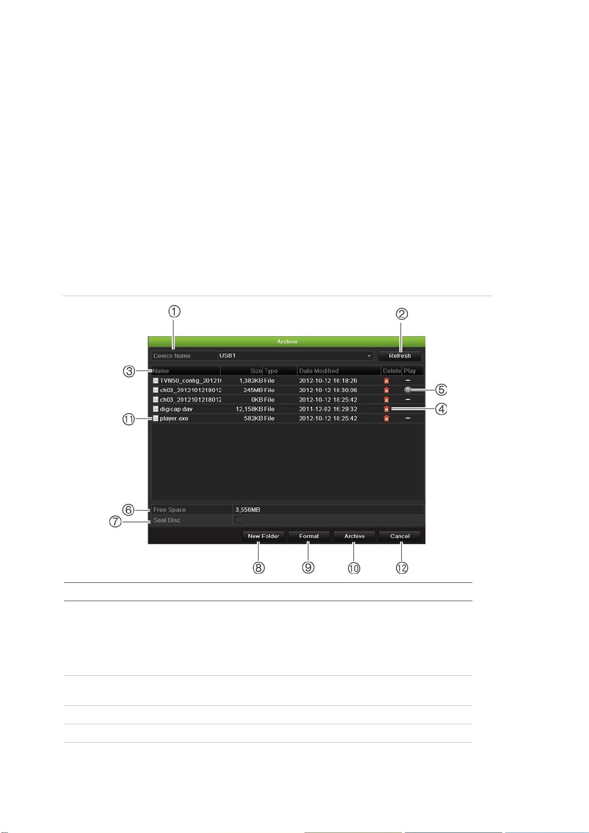
7BChapter 8: Archiving recorded files
Item
1
2
3
4
5
4. Click Start. The unit starts to download all the files listed.
Note: If there is a capacity limitation on the backup device, only the most
recent files will be backed up.
A message will appear to confirm when the download is complete.
Exporting recorded files to a backup device
You can insert a mini-USB hub to the USB port to attach a mouse for navigation
or a USB drive for archiving. However, the unit may not support all types of USB
hubs.
The Archive options available may depend on the type of backup device
selected.
Figure 26: Example of an archive
Function Description
. Device name Select one of the storage media for archiving. If the backup
device is not recognized:
• Click the Refresh button
• Reconnect device
• Check for compatibility from vendor
. Refresh Refresh the search results if any parameters have been
modified.
. Name Files found on the backup device are listed.
. Delete Click to delete a selected file from the backup device.
. Play Click to play selected file.
62 TruVision NVR 50 User Manual
Page 69

Chapter 9: Archiving recorded files
Item
6
7
8
9
10
11
12
Function Description
. Free space Free space available on the backup device is displayed.
. Seal disc Select to prevent other files being recorded onto the disc.
. New folder Create a new folder on the backup device. Files from the NVR
can be archived to a specific folder.
. Format Format the USB/eSATA drive.
. Archive Start downloading selected files onto the backup device.
. Player Backup Select to include a backup player.
. Cancel Cancel search and return to previous menu.
To export recorded files to a backup device:
1. Connect the backup device to the NVR.
If using a USB memory drive, insert the device into the USB port on the front
panel. If using a digital video disk (DVD) or eSATA drive, insert the disc into
the DVD drive. If both media are found in the TVN 50, the USB device takes
precedence over the DVD.
2. In live view mode press the Search button on the front panel or remote
control.
- Or Right-click the mouse and select Advanced Search.
The Advanced Search scr een app ear s .
3. Select the cameras and search parameters required.
Record type: All, constant, motion, text insertion, alarm, or manual.
File type: All, locked, or unlocked.
4. Click Search. The list of results appears.
5. Select the files to export.
Note: You can click the Play button to verify that the selected files are the
files to export.
6. Click Archive. The Archive screen appears.
7. Select the storage medium to ex por t to from the drop-down list.
8. Click Archive to begin the backup process.
9. Click OK when archiving is completed. Click Cancel until you return to live
view.
TruVision NVR 50 User Manual 63
Page 70

7BChapter 8: Archiving recorded files
Creating and archiving video clips
You can save important scenes in a recorded file for later reference by creating
video clips of selected portions of the file during playback. When an intruder, for
example, crosses in front of several cameras you can save the video clip of the
intruder’s path across these cameras in a single file.
Up to 30 video clips can be made from a recording.
Note: This feature is only available using the mouse.
To export video clips during playback:
1. Connect the backup device to the NVR.
2. Search for the required files to play back. See “Searching recorded video” on
page 53.
3. Select the file or files to play back and click Play. Playback starts
immediately.
4. Click the playback timeline where you want the video clip to start and click the
Start Clip button.
5. Click the playback timeline where you want the video clip to stop and click the
End Clip button.
6. Repeat for additional cl ips .
7. Exit playback mode. A message appears asking if you want to save the video
clips.
8. Click Yes to archive the clips. The Export screen appears.
Click No to exit and return to the search results screen. The clips are not
saved.
9. In the Export screen select from the drop-down list the backup device to be
used.
10. Click Start. File downloading starts.
Note: You can create a new folder for the video clips. Press the New Folder
button and enter the folder name.
Archiving snapshots
You can save all the video snapshots recorded to a backup device.
To archive snapshots:
1. Connect the backup device to the NVR.
2. Search for the required snapshot files to play back. See “Slideshow of
snapshots” on page 57. The list of snapshots appears.
3. Select the snapshots to backup.
64 TruVision NVR 50 User Manual
Page 71

Chapter 9: Archiving recorded files
4. Click Archive. Select the archiving device, if different from that listed.
5. Click Archive. Export starts immediately.
6. When completed, click OK. Click Cancel to return to the previous screen.
Managing backup devices
You can manage backup devices from the Export screen (see Figure 26 on page
62.)
The Export screen allows you to:
• Create New Folder: Create a new folder on the backup device.
• Delete: Delete a file or folder fr om the back up device.
• Play: Play the selected video file from the bac kup device.
• Format: Format the backup device.
• Erase: Erase files from a re-writable CD/DVD.
Playing back archived files on a PC
Use the standard file player software to play back the archived video on your PC.
It is downloaded automatically from the NVR when archiving files onto a backup
device.
TruVision NVR 50 User Manual 65
Page 72

7BChapter 8: Archiving recorded files
66 TruVision NVR 50 User Manual
Page 73

Chapter 9
Using the web browser
This chapter describes how you can use the web browser interface to configure
the device, play back recorded video, search through event logs, and control a
PTZ dome camera. You can also specify settings on the web browser interface to
optimize video playback and recording performance when operating in a low or
limited bandwidth envi r onm ent .
Windows Vista and 7 users
Internet Explorer for Windows Vista and Windows 7 operating systems have
increased security measures to protect your PC from any malicious software
being installed. When using the NVR web browser interface, you can install
ActiveX controls to connect and view video using Internet Explorer.
To have complete functionality of the web browser interface and the NVR player
with Windows Vista and Windows 7, do the following:
• Run the Browser inter f ace and the NVR player application as an administrator
in your workstation
• Add the NVR’s IP address to your browser’s list of trusted sites
To add the NVR’s IP address to Internet Explorer’s list of trusted sites:
1. Open Internet Explorer.
2. Click Tools, and then Internet Options.
3. Click the Security tab, and then select the Trusted Sites icon.
4. Click Sites.
5. Clear the “Require server verification (https:) for all sites in this zone” box.
6. Enter the IP address or DDNS name in the “Add this website to the zone”
field.
7. Click Add, and then click Close.
8. Click OK in the Internet Options dialog screen.
9. Connect to the TVN 50 for full browser functionality.
TruVision NVR 50 User Manual 67
Page 74

8BChapter 9: Using the web browser
HTTP port: 80
Server/Client software port: 8000
Accessing the web browser
To access the TVN 50, open a web browser and enter the IP address assigned
to the TVN 50, as a web address. On the logon screen, enter the default user ID
and password.
Note: Only one NVR can be viewed per browser.
User ID: admin
Password: 1234
The default values for TVN 50 network settings are:
• IP address - 192.168.1.82
• Subnet mask - 255.255.255.0
• Gateway address - 192.168.1.1
• Ports:
When using the browser:
RTSP port: 554
For more information on port forwarding, see Appendix C “Port forwarding
information” on page 135.
When using TruNav:
RTSP port: 554
Web browser overview
The NVR web browser lets you view, record, and play back videos as well as
manage all aspects of the NVR from any PC wi th Internet acc ess . T he brow s er ’ s
easy-to-use controls give you quick access to all TVN 50 funct ions . S ee
Figure 27 below.
68 TruVision NVR 50 User Manual
Page 75
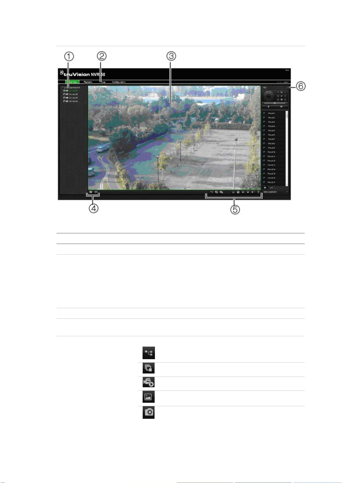
8BChapter 9: Using the web browser
Item
1
2
3
4
5
Figure 27: Live view in the web browser interface
Table 16: Description of live view in the web browser
Name Description
. Camera View video and record video from the selected camera.
. Menu toolbar Lets you do the following:
• View live video
• Play back video
• Search for event logs
• Configure settings
• Log out of the interface
. Viewer View live or playback video.
. Display format Define how you want video to be displayed in the viewer:
Multiview or full screen.
. Video function toolbar Lets you do the following in live view:
Switch between mainstream and substream.
Start/stop all streaming from selected cameras.
Start recording from selected cameras.
Turn POS/ATM text insertion on/off.
Take a video snapshot.
TruVision NVR 50 User Manual 69
Page 76

8BChapter 9: Using the web browser
Item
6
Name Description
. PTZ panel Hide/display the PTZ panel.
View previous and next camera respectively.
If viewing in multiview format, live view moves to the
next group of cameras for the selected number of video
tiles.
Turn audio on/off
Turn microphone on/off
Using the web browser to configure the device
Click Configuration on the browser menu bar to display the configuration
screen. There are two ways to configure the NVR: Local and Remote.
Local configuration
Local configuration lets you define communication and network parameters such
as protocol type, maximum file size, stream type and network transmission
settings. You can also specify the directory locations for saving recorded and
playback video, captured images, and downloaded files.
Remote configuration
Remote configuration lets you remotely configure the foll owing NVR settings:
• NVR information including device name, number, and overwrite option as well
as time and holiday settings.
• Camera settings including motion detection, privacy masking, video loss,
video tampering, video image display settings, and text overlay
• Recording settings including recording schedule and recording quality
• Network settings including, e-mail, DDNS, and NTP setup
• Serial port settings including RS-485 and RS-232 para met er s
• Alarm settings including alert notifications, audio alerts, pre-alarm, and postalarm seconds, and notification parameters
• System settings including, user management, date and time, audio, RS-485,
RS-232, language, alarm notification, and hard drive setup
See Figure 28 below. Please refer to the specific chapters on this manual for
detailed information on configuring the differe nt func ti o ns .
70 TruVision NVR 50 User Manual
Page 77
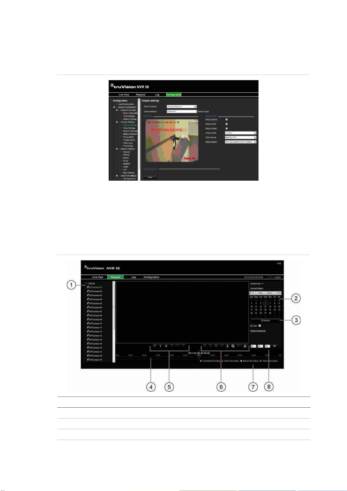
8BChapter 9: Using the web browser
Ite
1
2
3
Note: The configuration settings defined remotely are different from those that
can be defined locally.
Figure 28: Remote browser configuration screen (Display Settings window shown)
Searching and playing back recorded video
To search and play back recorded video, click Playback on the menu bar to
display the Playback page shown in Figure 29 below.
Figure 29: Browser playback page
m Description
. Selected camera.
. Calendar: Selected day is highlighted.
. Search: Click to start searching recorded files for the selected camera.
TruVision NVR 50 User Manual 71
Page 78
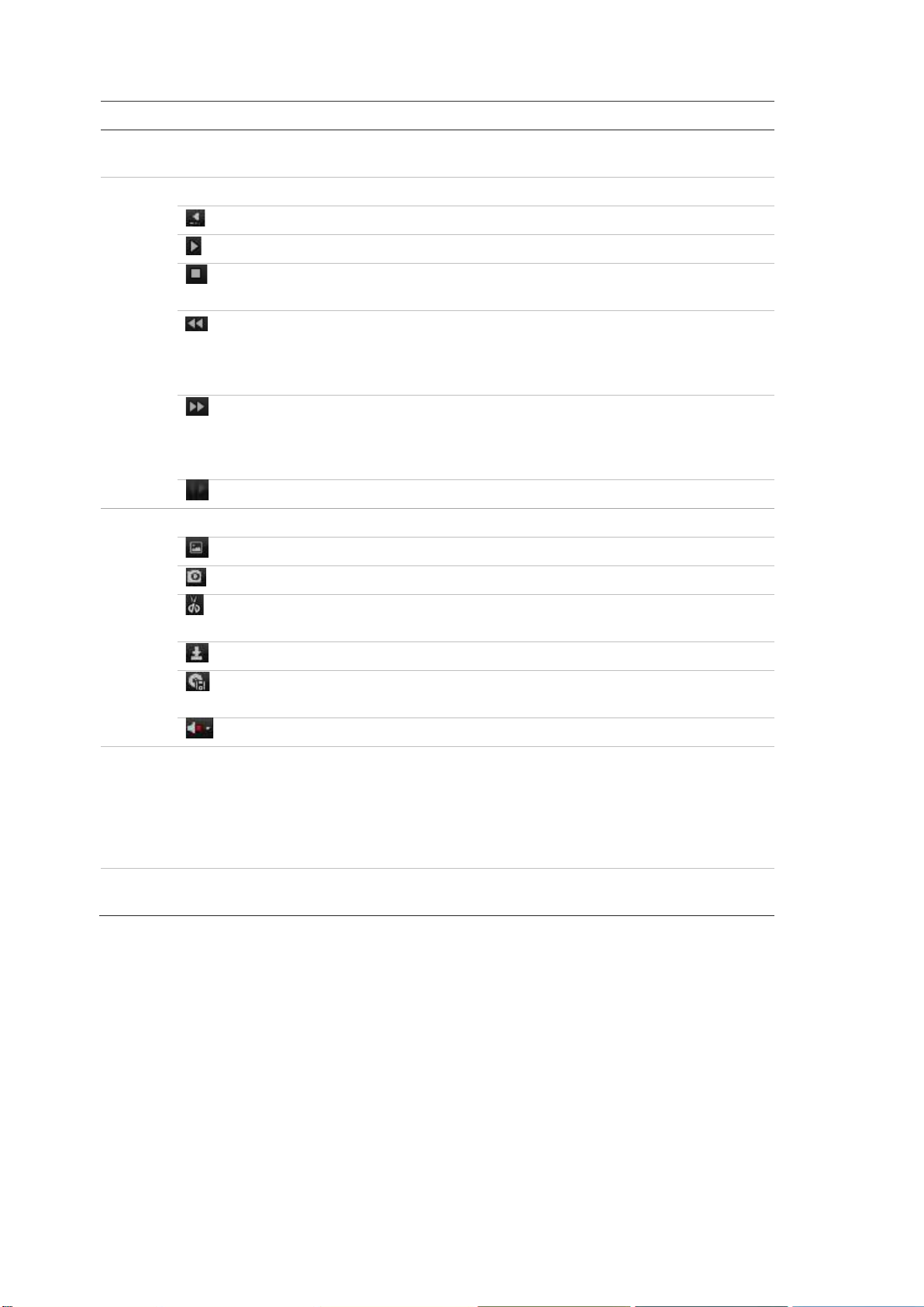
8BChapter 9: Using the web browser
Ite
4
5
6
7
8
m Description
. Timeline: The timeline moves left (oldest video) to right (newest video). Click a
location on the timeline to move the cursor to where you want playback to start.
. Playback control toolbar:
Reverse: Click to reverse playback.
Start/stop: Start or stop playback.
Stop playback. Timeline jumps back to 00:00:00 time (midnight) of the
previous day.
Playback slow forward: Click to scroll through the different speeds
available: single frame, 1/8 speed, ¼ speed, ½ speed, normal, X2 speed,
X4 speed, X8 speed, maximum speed. Current speed is displayed under
the camera name on top right of window.
Playback fast forward: Click to scroll through the different speeds
available: single frame, 1/8 speed, ¼ speed, ½ speed, normal, X2 speed,
X4 speed, X8 speed, maximum speed. Current speed is displayed under
the camera name on top right of window.
Single frame: Click to play back one frame at a time.
. Audio and video control toolbar:
Text insertion: Click to enable/disable POS/ATM text display in playback.
Snapshot: Capture a snapshot of the video.
Video clips: Start/stop video clip during playback. Sections of a recording
can be saved to an external storage device.
Download: Download video clips.
Backup: Click to make back up of recorded files to save locally on the
NVR. A list of the recorded files appears
Audio: Click to enable/disable audio.
. Type of recording:
Green: Indicates video recorded based on the recording schedule defined.
Red: Indicates video recorded triggered by an alarm event.
Yellow: Indicates video recorded triggered by motion detection.
Blue: Indicates video recorded triggered by a POS/ATM text recording.
. Jump start: Enter a precise time in the box and click the Go To button to jump start
the playback at this selected time.
Select a camera and a day to search from on the calendar displayed, and then
click Search. The timeline below the page indicates video recorded for the
specified day. The timeline also classifies by color the type of recording with each
type.
Click and drag the marker across the timeline on where you want video playback
to begin, and then click Play on the playback control toolbar. You can capture a
snapshot of a video image, save the video playback, or download the recorded
video.
72 TruVision NVR 50 User Manual
Page 79
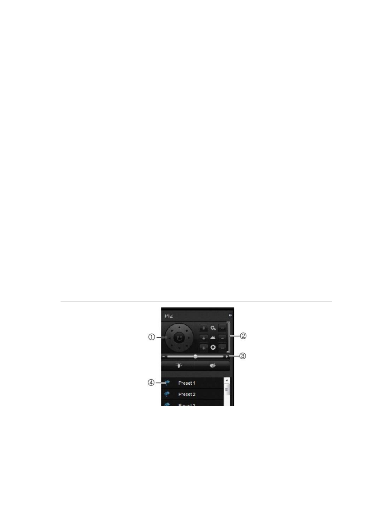
8BChapter 9: Using the web browser
Searching for event logs
The NVR compiles a log of events, such as the start or end of video recording,
NVR notifications, and alar ms, thr oug h w hi ch you can easily search. Logs are
categorized by the following types:
• Alarm: Includes motion detection, tamper detection, video tampering, and
other alarm events
• Notifications: Includes system notifications such as video loss, HDD failures,
and other system-related events
• Operations: Includes users access to the web interfaces and other
operational events
• Information: Includes general informati o n on the NVR actions, such as the
start and end of video recording, etc.
To search for logs, click Log on the menu bar, select a log type, specify a date
and time range, and then click Search.
Controlling a PTZ dome camera in the web browser
The web browser interface lets you control the PTZ functions of a dome camera.
Click a PTZ dome camera and use the PTZ controls on the interface to control
the PTZ functions.
Figure 30: PTZ controls
1. Directional pad/auto-scan buttons: Controls the movements and directions of the PTZ. Center
button is used to start auto-pan by the PTZ dome camera.
2. Adjust zoom, focus, and iris.
3. Adjust speed of PTZ dome camera.
4. Start selected preset.
TruVision NVR 50 User Manual 73
Page 80
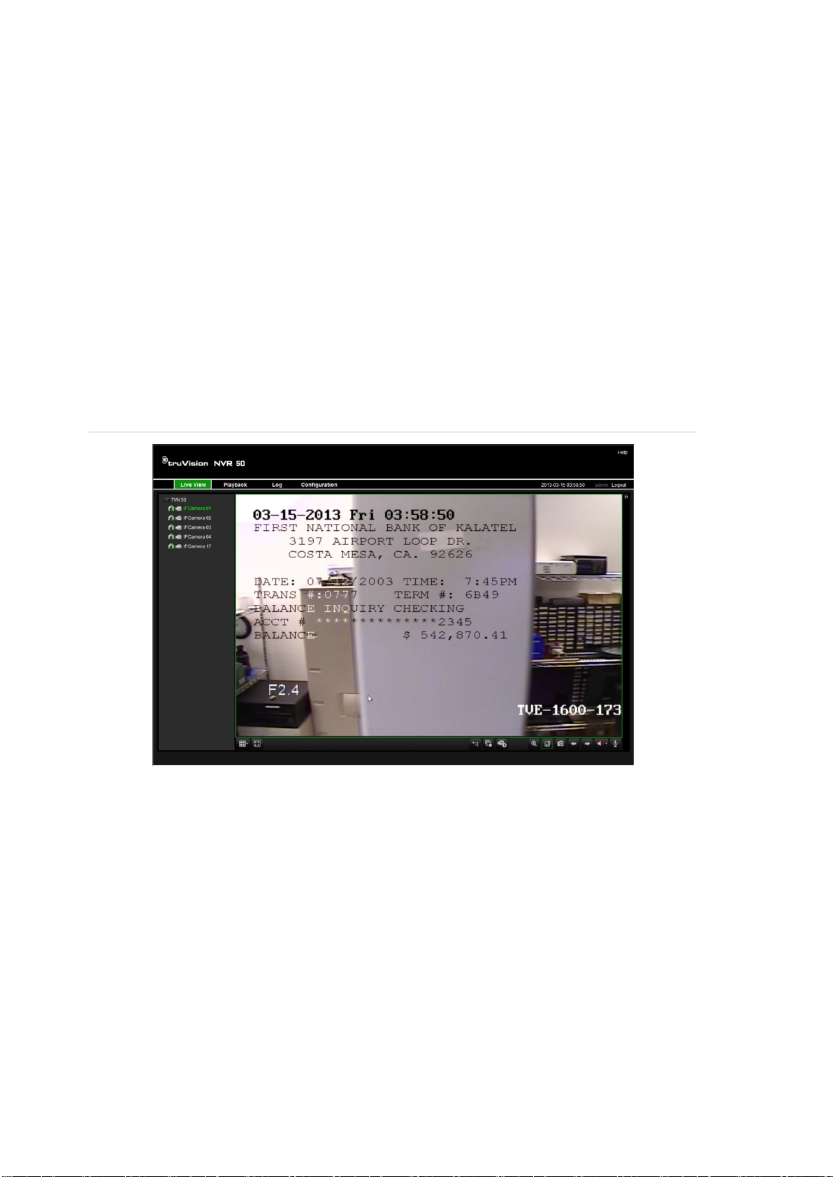
8BChapter 9: Using the web browser
Capturing text insertions
Text insertion lets you insert or display text from a point-of-sale (POS) system on
the video display of the NVR. The tex t is saved and time‐stamped to g ether w i th
the video. You can then search the text for specific video clips. The text is
displayed during playback.
The NVR supports POS and ATM text insertion via the UTC ProBridge accessory
connected to the RS-232 port on the NVR. This feature is currently only available
using the browser.
In both live view and playback, a camera set up for text insertion will display the
video with the POS text overlay.
See Figure 31 below for an example of a video image in live view with text
insertion.
Figure 31: Example of a video image with text insertion
To set up text insertion:
1. Click the Configuration tab in the browser toolbar and then select 232 Serial
Port.
2. Under Usage, select ProBridge.
3. In the submenu panel, select Text Insertion.
4. Check Enable text insertion.
5. Select the access device from the drop-down list.
6. Select the access mode. Only “ProBridge” is listed.
7. Under Start String, enter the desired transaction text, such as an ATM
transaction number.
8. Click Apply to save the settings.
74 TruVision NVR 50 User Manual
Page 81
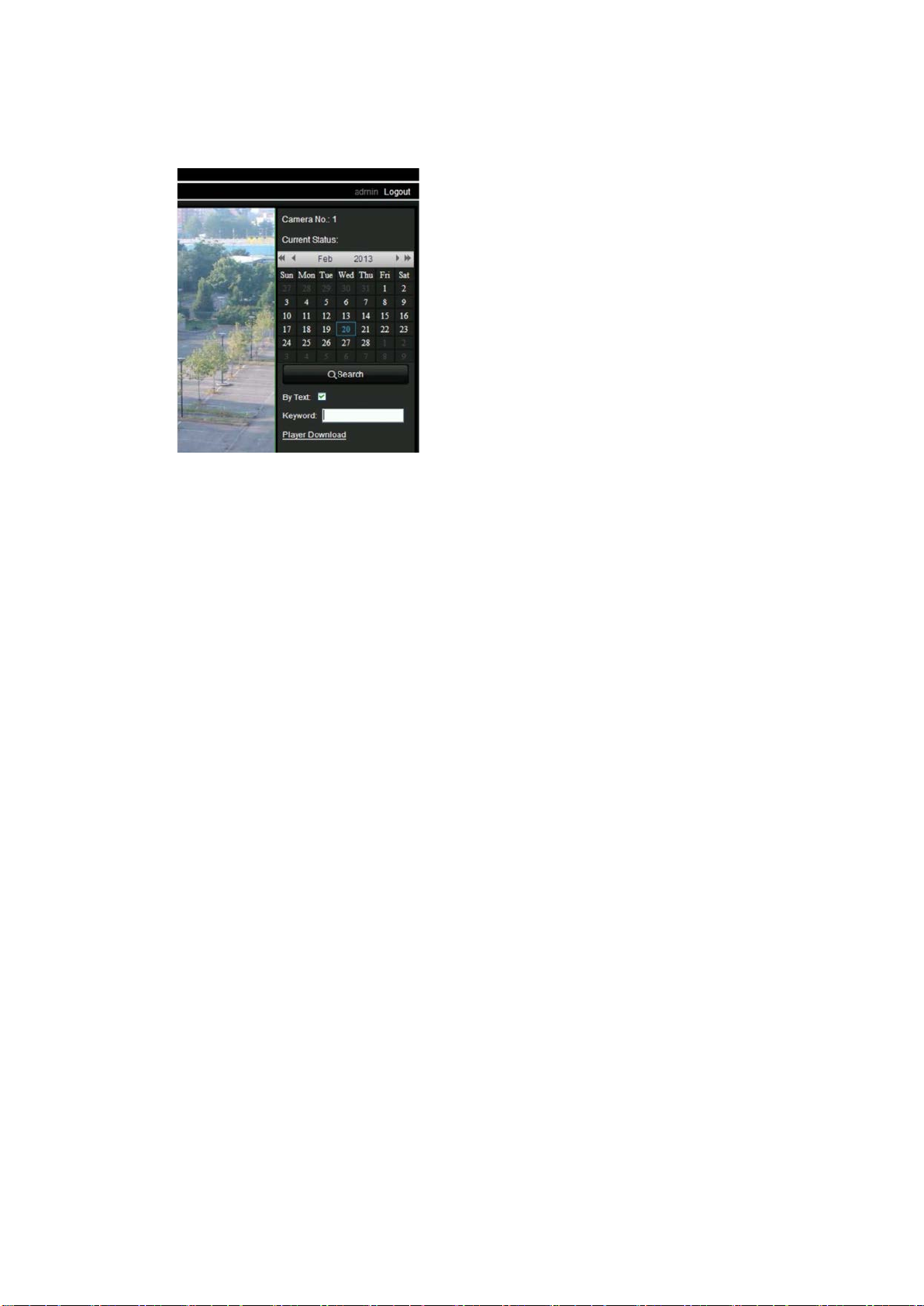
8BChapter 9: Using the web browser
To search text insertion in recorded video:
1. In live view, check the By text check box.
2. In the keyword text box that appears, enter the text for which you want to
search.
Text overlay
You can add up to eight lines of text on screen via the browser. This option can
be used, for example, to display emergency contact details. By default these
lines of text are positioned along the top of the screen. The strings follow each
other consecutively.
Note: This option is not available via the NVR.
To add on-screen overlay text:
1. Click the Configuration tab in the browser toolbar and then select Camera
Settings > Text Overlay.
2. Select the desired camera.
3. Check the string box 1 for the first line of text.
4. Enter the text for string 1 in the column alongside. Up to 22 alphanumeric
characters can be used.
5. Repeat steps 3 and 4 for each extra line of text, selecting the next string
number.
6. Click Save.
Using a network storage system
You can use a network storage system (NAS) or storage area network (SAN) to
remotely store NVR recordings.
TruVision NVR 50 User Manual 75
Page 82

8BChapter 9: Using the web browser
To set up a network storage system:
1. Click the Configuration tab in the browser toolbar and then select Network
Settings > NetHDD.
2. On the firs t line of HDD No., enter the IP address of the desired remote
storage system.
3. Enter the file path name to define where on the remote storage system you
want to store the files.
4. Under Type, select type of storage system to be used: NAS or SAN. Default
is NAS.
5. Up to eight remote storage systems can be set up.
6. Click Save.
76 TruVision NVR 50 User Manual
Page 83
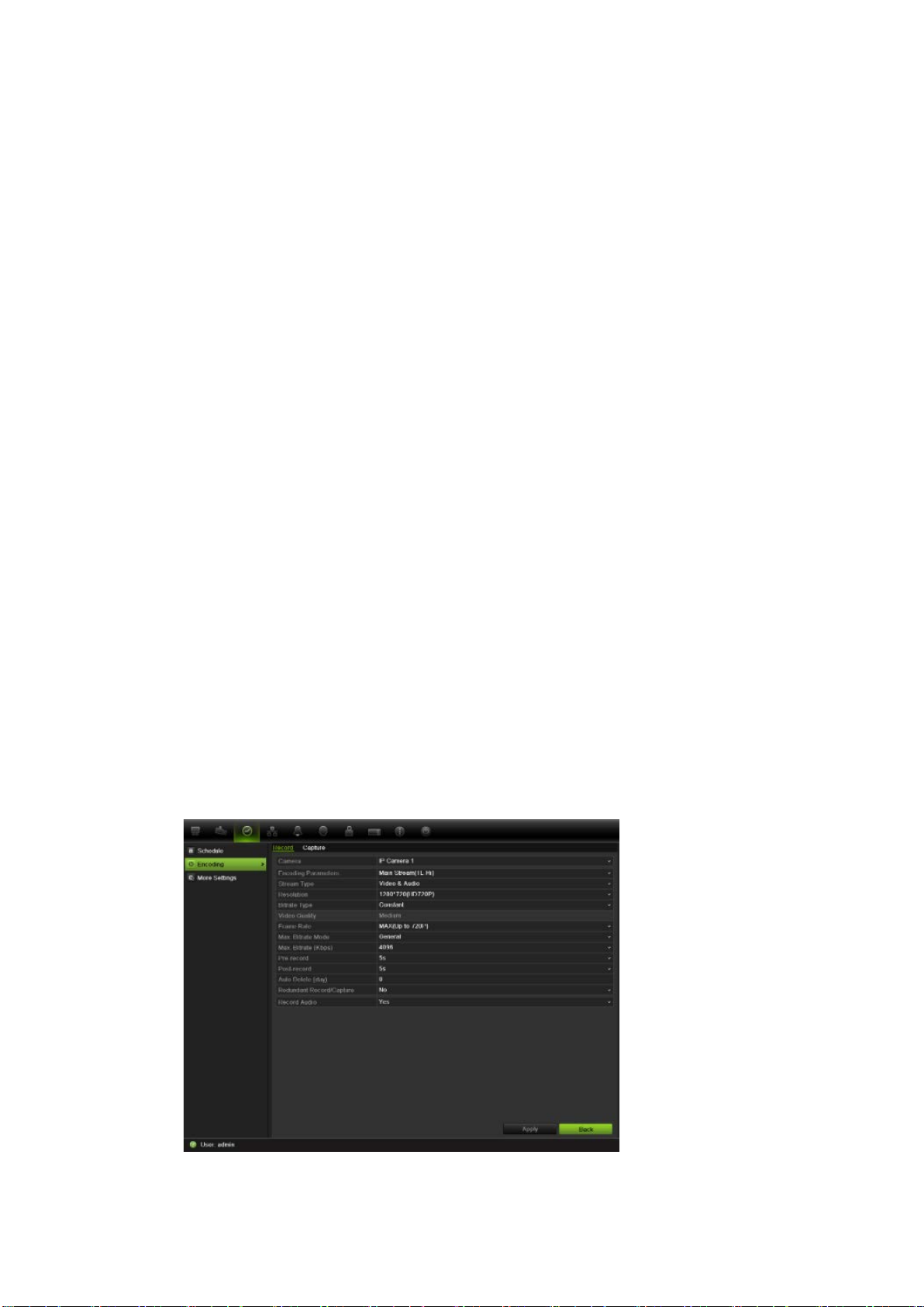
9BChapter 10: Recording
Chapter 10
Recording
This chapter provides instructions on how to define the recording settings of your
NVR. This chapter covers how you can configure your initial recording settings,
schedule recordings, protect your recorded files, and set up your HDD for
redundancy.
Initializing recording settings
Before you can set up your NVR to begin recording, you must first configure
general recording settings for the IP cameras.
Ensure that the HDD has been installed and initialized before configuring the
recording settings. See Chapter 13 “HDD management” on page 105 for more
information.
To configure recording settings:
1. Click the Video Sche dule icon in the menu toolbar.
2. Select Encoding > Record.
3. Select the camera you want to configure.
TruVision NVR 50 User Manual 77
Page 84

9BChapter 10: Recording
4. Configure the followi ng recording settings:
• Encoding parameters: Select one of the stream types: Mainstream (TL-
Hi, Mainstream (TL-Lo), Mainstream (Event), Mainstream (Alarm), or
Substream.
• Stream type: Select the type of stream to record, either video or video
and audio.
• Resolution: Select the resolution of the recording.
• Bit rate type: Select Constant or Variable.
• Video quality: Select the quality at which to record. If “Variable” was
selected as the bit rate type, this option is unavailable.
• Frame rate: Select the recording frame rate. 25 PAL (30 NTSC), 20, 18,
16, 15, 12, 10, 8, 6 (default), 4, 2, 1, 1/2, 1/4, 1/8, 1/16. Default is 25 (30).
• Max bit rate mode: Select the general default or customized option.
• Max bit rate (kbps): If the customized maximum bit rate mode was
selected, enter the value here. It must be between 32 and 8192 kbps. It is
calculated from the frame rate and time required.
• Pre-record: This is the time the camera starts recording before the
scheduled time or event. Select the time in seconds to start pre-recording
before the scheduled time or event.
The maximum pre-recor ding times available depend on the cons tan t bit
rate. See “Maximum pre-recording times” on page 135 for more
information.
• Post-record: This is the time the camera continues to record after the
scheduled time or event. Select the time in seconds to stop post-recording
after the scheduled time or event.
• Auto-delete (day): Select the number of days after which recorded video
from the specified camera is permanently deleted from the HDD. A “day”
is defined as the 24-hour period from when the auto delete mode (ADM)
was set.
The maximum number of days that can be set is 60. However, the actual
number of days permitted depends on the HDD capacity. If the value is set
to ‘0’, the option is disabled.
• Record audio: Select Yes to record sound with the images.
5. Click Apply to save the settings.
6. If you want to save these parameters to another camera, click Copy and
select the camera in the pop-up screen that appears. Click OK and return to
the main screen.
7. Click the Capture tab and configure the settings for captured video, such as
snapshots. Click Apply to save the settings.
8. Click Back to return to live view.
78 TruVision NVR 50 User Manual
Page 85

9BChapter 10: Recording
Using an external recording device
You can use an external storage device, such as an eSATA HDD, to backup
video or to add its recording capacity to that of the NVR itself. If you chang e t his
option, you must reboot the NVR to implement the change.
To configure for an external recording device:
1. Click the Video Sche dule icon in the menu toolbar.
2. Select More Settings.
3. Select one of the two options:
Record and Capture: Extend the recording capacity of the NVR.
Export: Backup data onto an eSATA backup dev ic e.
Note: If the external storage device is part of the total internal capacity of the
NVR, then it is no longer available for backing up video.
4. Click Apply.
Configuring overwrite
You can select how the NVR responds when the HDDs become full and there is
no longer sufficient space to save new data.
To configure for overwrite when the HDDs are full:
1. Click the Video Sche dule icon in the menu toolbar.
2. Select More Settings.
3. Under Overwrite, select Yes.
Defining a recording schedule
Defining a recording schedule lets you specify when the NVR records video and
under what circumstances. Each camera can be configured to have its own
recording schedule.
The schedules are visually presented on a map for easy reference. See
Figure 32 below for an example.
TruVision NVR 50 User Manual 79
Page 86
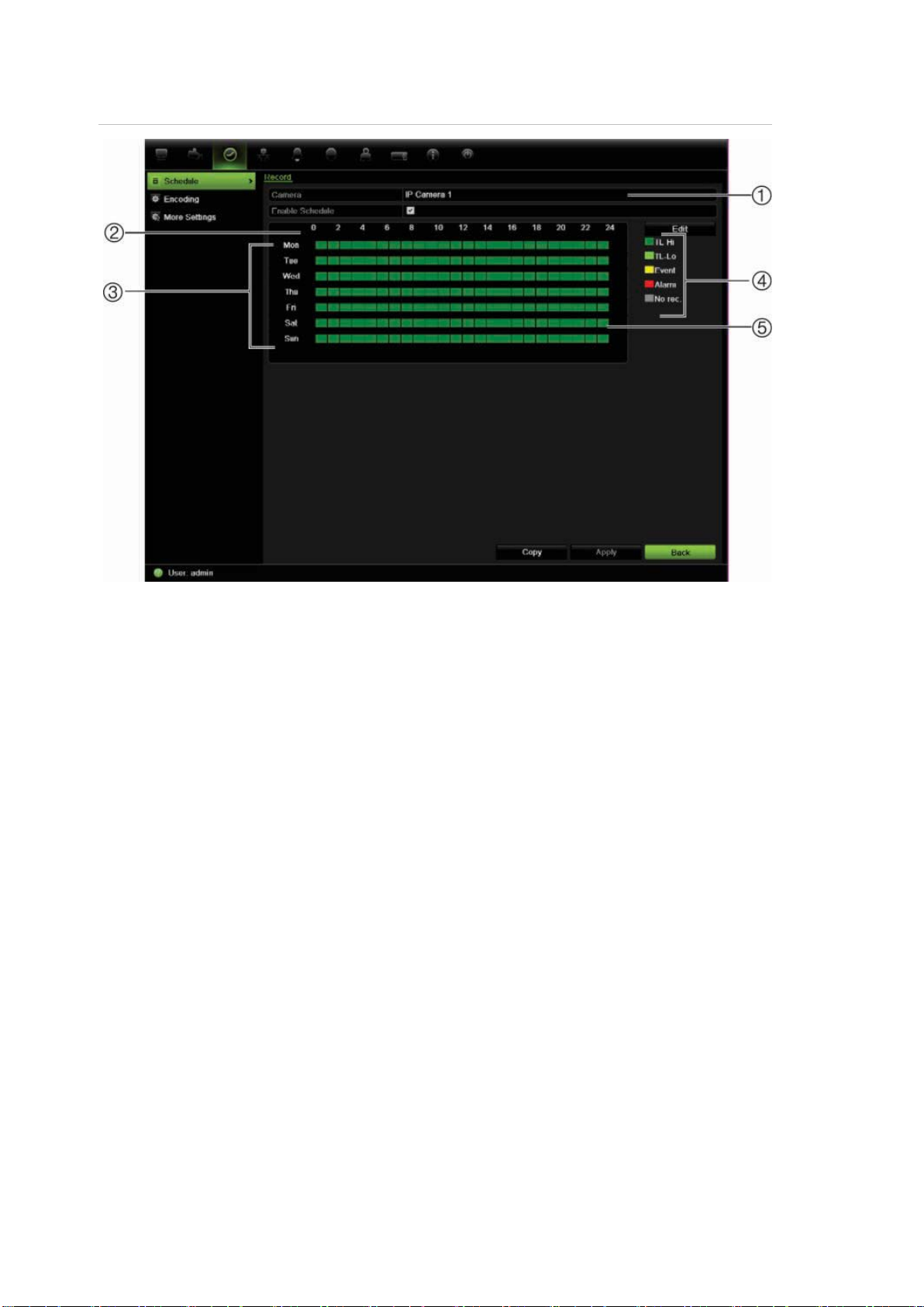
9BChapter 10: Recording
Figure 32: Description of the Schedule screen
1. Camera. Select a camera.
2. Schedule time. Represents the 24-hour c ycle during w hich a sc hedu le is selec te d.
3. Schedule day. There are seven days to select: Sunday (Sun), Monday (Mon), Tuesday
(Tue), Wednesday (Wed), Thursday, (Thu), Friday (Fri), and Saturday (Sat).
4. Recording type. There are five recording types to select, which are color-coded:
TL Time lapse (Green squares): Record of a specific day. Each green square in the timeline
represents an hour in the 24-hour period.
TL-Hi (Dark green): High quality time lapse. Records high quality video.
TL-Lo (Bright green): Low quality time lapse. Records low quality video. This could be used,
for example, for night recordings when few events or alarms are expected. Saving the
video in low quality helps save resources on the HDD.
Event (Yellow): Records only events, such as motion detection and POS/ATM text insertion.
Alarm (Red): Records only alarms.
None (Grey): No recording during this period.
5. Timeline. There is a 24-hour time line for each day. Up to eight recording periods can be
scheduled during the 24-hour period.
Daily schedules
To set up a daily recording schedule:
1. Click the Video Sche dule icon in the menu toolbar and select Schedule.
2. Select a camera.
80 TruVision NVR 50 User Manual
Page 87
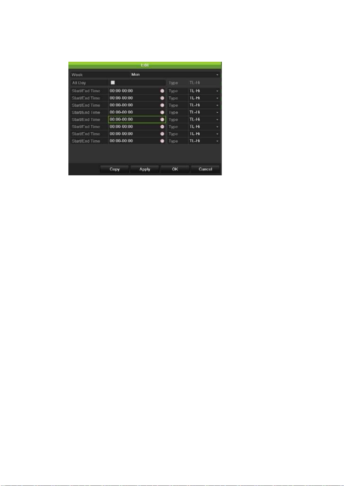
9BChapter 10: Recording
3. Check the Enable Schedule box.
4. Click Edit. The following screen is displayed:
5. Select the day of the week for which you want to set up the schedule.
You can define a schedule for each day of the week.
6. Set the start and end time for recording.
Define a time period by entering a start (left column) and end (right column)
time. You can schedule up to eight time periods. Click All Day to record all
day.
Note: Time periods defined cannot overlap.
7. Select a recording type.
This setting instructs the NVR to begin recording when an alarm is triggered.
The recording type can be based on time and triggered by motion detection
and/or an alarm. If set to TimeLapse (TL-Hi or TL-Lo), the NVR records
continuously.
8. Click Apply to save settings
9. Repeat steps 3 to 8 for other days of the week or to copy the schedule
settings to another day.
To copy the current schedule settings to another day of the week, click Copy.
Select the number of the day of the week to which to copy the schedule and
click OK to save changes and return to the Edit screen.
10. Repeat steps 3 to 9 for other cameras.
11. Click Apply to save the settings and then OK to return to the schedule
screen.
TruVision NVR 50 User Manual 81
Page 88
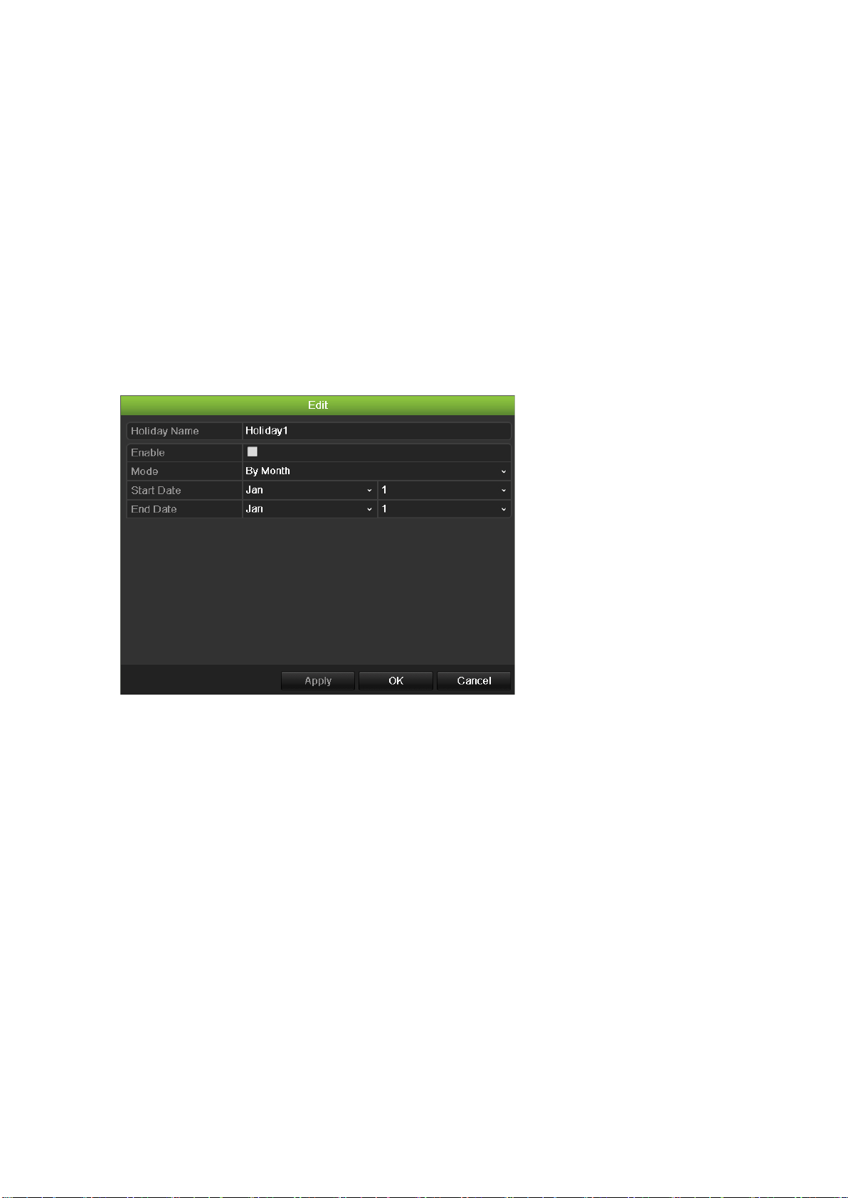
9BChapter 10: Recording
Holiday schedules
As well as being able to schedule when recordings occur during the week, you
can also schedule them for specific holidays in the year such as the first of
January, or the second Wednesday of every month. You can schedule up to 32
holiday periods.
A holiday period can be scheduled for a particular day or as a block of days.
To set up a holiday recording schedule:
1. Click the Display Mode Settings icon in the menu toolbar and select
Holidays.
2. Select a holiday period from the list and click Edit to modify the settings. The
Edit screen appears.
3. Enter the name of the holiday period and click Enable.
4. Select whether the holiday period will be categorized by date, week or month
and then enter the start and end dates.
5. Click Apply to save the settings and then OK to return to the Edit screen.
6. Repeat steps 2 to 5 for other holiday periods.
7. Click Back to return to live view.
Motion detection schedules
For IP cameras you can configure from the NVR the schedule when the camera
can be triggered by motion. However, you need to configure the area of the video
display sensitive to motion from the camera itself.
For information on scheduling motion detections, see “Motion detection set up”
on page 88.
82 TruVision NVR 50 User Manual
Page 89
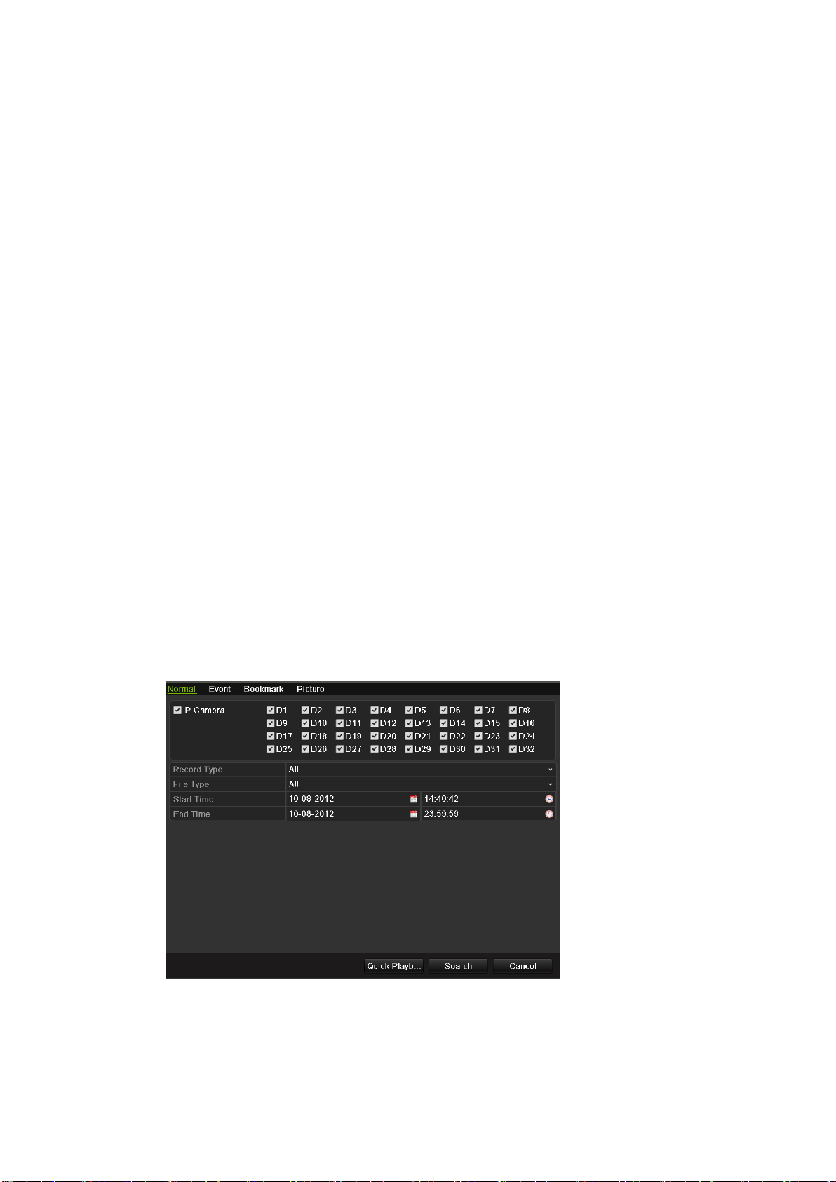
9BChapter 10: Recording
External alarm schedules
The NVR can be scheduled to record when an alarm is triggered by an external
alarm device such as a PIR detector or dry contacts. For information on
scheduling external alarms, see “Triggering or clearing alarm outputs manually”
on page 93.
Protecting recorded files
There are two methods to prevent recorded files from being inadvertently
overwritten or deleted off the HDD. We highly recommend that important
recorded events be protected from deletion. Recorded files can either be locked
or the HDD that the files reside on can be set to read only.
Locking and unlocking recorded files
Lock files to protect them against being overwritten or deleted.
To lock or unlock a recorded file:
1. In live view enter the video search screen by pressing the Search button on
the front panel or remote control, and then enter Advanced Search.
— Or —
In live view right-click the mouse to display the pop-up menu and selec t
Advanced Search.
The Search screen ap pear s .
2. Search for the desired recording by entering the search parameters, which
include the camera number, record type, file type, and start time and end
time.
3. Click Search.
TruVision NVR 50 User Manual 83
Page 90
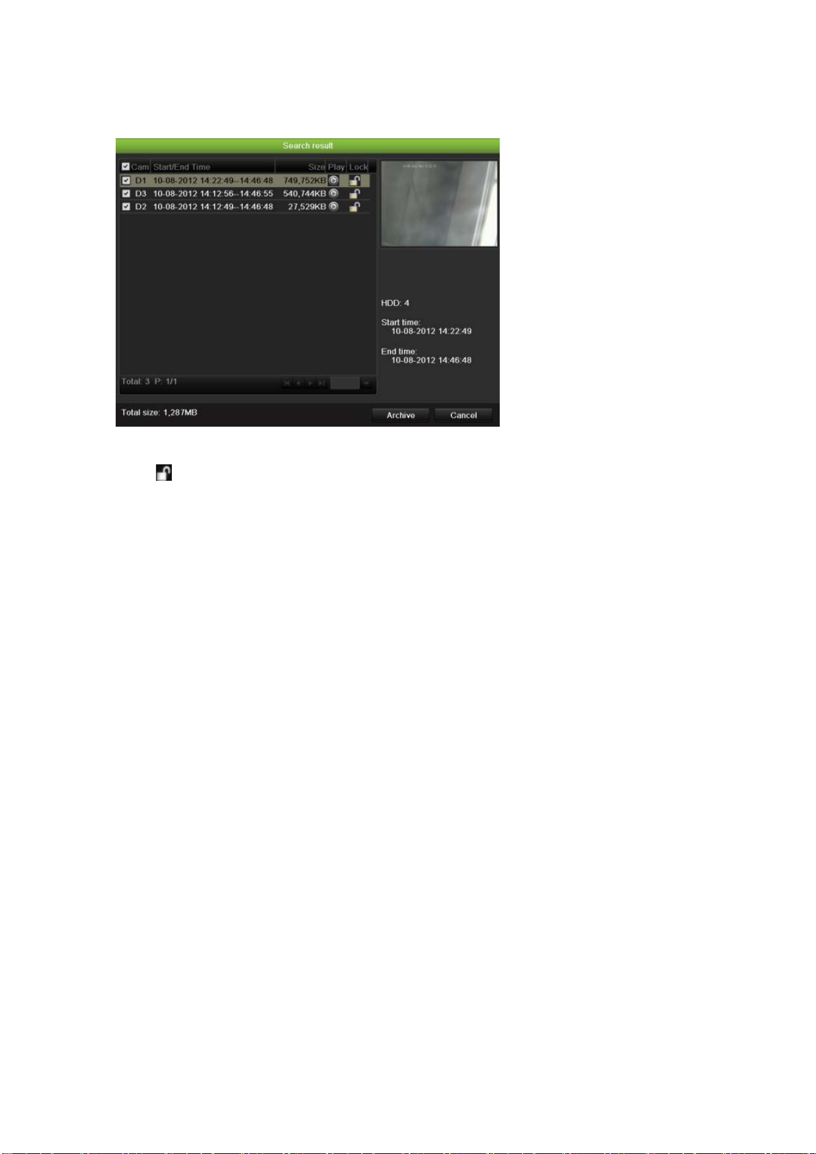
9BChapter 10: Recording
A list of recordings, similar to the figure below, matching the search
parameters is displayed.
4. Select the file you want to lock/unlock.
5. Click to lock a file. Click again to unlock.
The Locked column indicates whether a file is locked or not. Closed lock
icons indicate locked files while opened lock icons indicate unlocked files. The
Lock button toggles between Lock and Unlock, depending on the file.
6. Click Cancel to return to live view.
Setting the HDD to read-only
When you set an HDD to read-only, recorded video files cannot be written to the
HDD. If multiple HDDs are used, the NVR automatically records to the next HDD
not set to read-only
To set a HDD to read-only:
1. Click the System Setting icon in the menu toolbar.
2. Click Hard Disk to set up the HDD parameters.
3. Select the HDD you want to set to read-only.
4. Check Read only.
5. Click Apply to save the settings. The HDD is now read-only.
Note: In order to enable recordings on that particular HDD again, you must
set the HDD status back to R/W (Read/ Write).
84 TruVision NVR 50 User Manual
Page 91
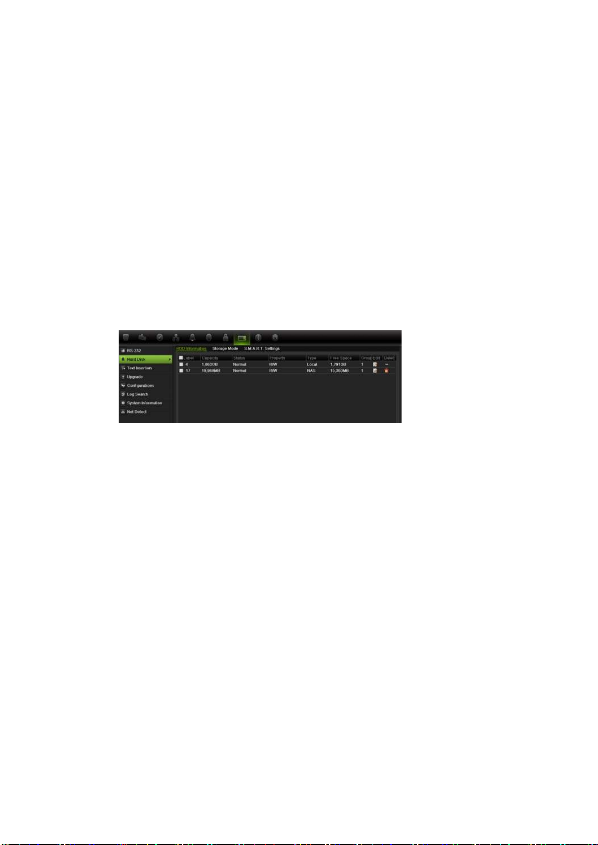
9BChapter 10: Recording
Configuring redundant recording
Setting up HDD redundancy lets your NVR redundantly record a copy of the
videos onto multiple drives as a safeguard against losing all your files in case of
disk failures. This process is also known as mirroring. You must have more than
one HDD in your NVR to set up HDD redundancy.
Redundancy significantly reduces the storage capability of the HDDs. As a result
you need to double your capacity to record video over a given time.
Note: You must set the storage mode of the HDD to Group before configuring
the redundancy. See “Setting up HDD groups” on page 106 for more
information.
To set up HDD redundancy:
1. Click the System Setting icon in the menu toolbar and select Hard Disk.
2. Click the HDD Information tab and select the HDD to be used for
redundancy and click Edit.
3. In the Local HDD Settings screen, select Redundancy.
Verify at least one other HDD is set to R/W (read/write).
4. Click Apply to save the settings and then OK return to the previous screen.
5. In the menu toolbar, click the Video Schedule > Encoding.
6. Select the camera to be used for redundancy.
7. Check Redundant Record/Capture.
8. Click Apply to save the settings.
9. Repeat steps 7 to 9 for other cameras whose files you would like to be
redundantly recorded.
10. Click Back to return to live view.
Note: The HDD set to redundancy stores an extra copy of the recording.
When an HDD is set to redundancy, at least one other HDD must be set to
the R/W status.
TruVision NVR 50 User Manual 85
Page 92

9BChapter 10: Recording
86 TruVision NVR 50 User Manual
Page 93

Chapter 11
Alarm settings
This chapter describes setting up how the system will respond when an alarm is
triggered.
Description of alarm notification types
When setting up the rules for alarm detection, you can specify how you want the
NVR to notify you about an alarm or event. You can select more than one
notification type. Not all notifications types are available for all types of alarms.
The alarm notification types are:
• Audible warning: Triggers an audible beep when a notification or alarm is
detected.
• Notify surveillance center: Sends a signal to TruVision Navigator or other
software applications when an alarm or notification is detected.
• Trigger alarm output: Triggers an alarm output when a notification is
detected for an external alarm. See “Setting up ex ter nal al ar ms” on page 90
for information on configuring an alarm output.
• Send e-mail: Sends an e-mail when an alarm or notification is detected. See
“Configuring e-mail” on page 100 for information on how to configure the NVR
to send an e-mail.
• Full screen monitoring: When an alarm is triggered, the local spot monitor
(VGA or BNC monitor) displays an image in live view mode. For alarms that
are triggered simultaneously, images display one at a time ever y 10 secon ds
(default dwell time). You can set a different dwell time using the Dwell Time
setting under the Display Settings>Layout screen. When the alarm stops,
cycling of the images stops and you return to live view mode. This alarm
option must be selected for each channel where it is required..
This alarm notification is not av ai l able for sy s t em al ar ms.
TruVision NVR 50 User Manual 87
Page 94
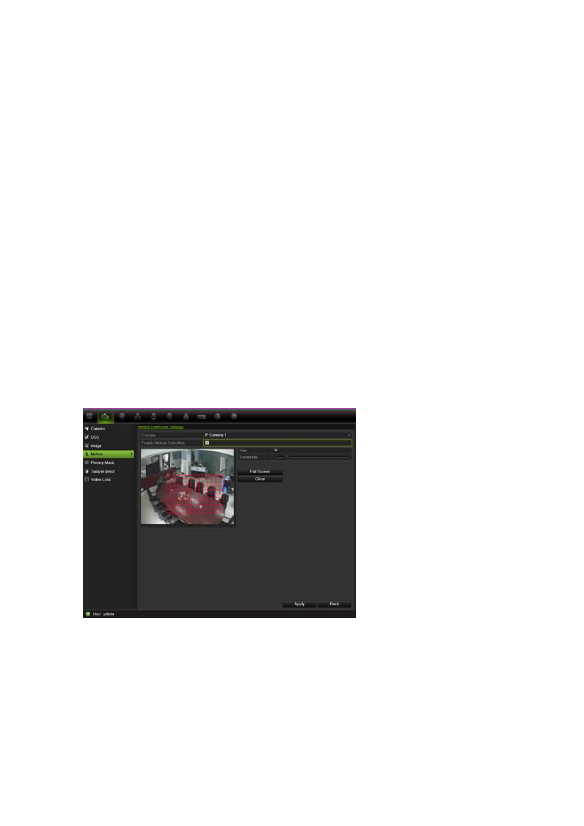
10BChapter 11: Alarm settings
Setting up motion detection
Motion detection is one of the most important features of a NVR. With it there is
no need to manually search through hours of video recordings to find an event.
The NVR can be set up to trigger an alarm if it detects motion and to record it.
You can then search these recorded motion activities for specific incidents. If
enabled, motion detection recording can help increase the number of days your
NVR can record.
You can mask out any areas of motion on an IP camera display that you do not
want to trigger a recording such as a flag on a pole or a moving tree.
Select the level of sensitivity to motion as well the target size so that only objects
that could be of interest can trigger a motion recording. For example, recording
is triggered by the movement of a person but not that of a cat.
You can set up the schedule from the NVR when the camera can be triggered by
motion. However, you need to configure the area of the video display sensitive to
motion from the IP camera itself.
Motion detection set up
To set up motion detection:
1. Click the Camera Management icon in the menu toolb ar and select Motion.
2. Select the IP camera to detect motion. Each camera must be set up
individually.
3. Check Enable Motion Detection.
Note: This option is only available for IP cameras. The button is inactive for
IP cameras.
4. Select the areas sensitive to motion.
88 TruVision NVR 50 User Manual
Page 95
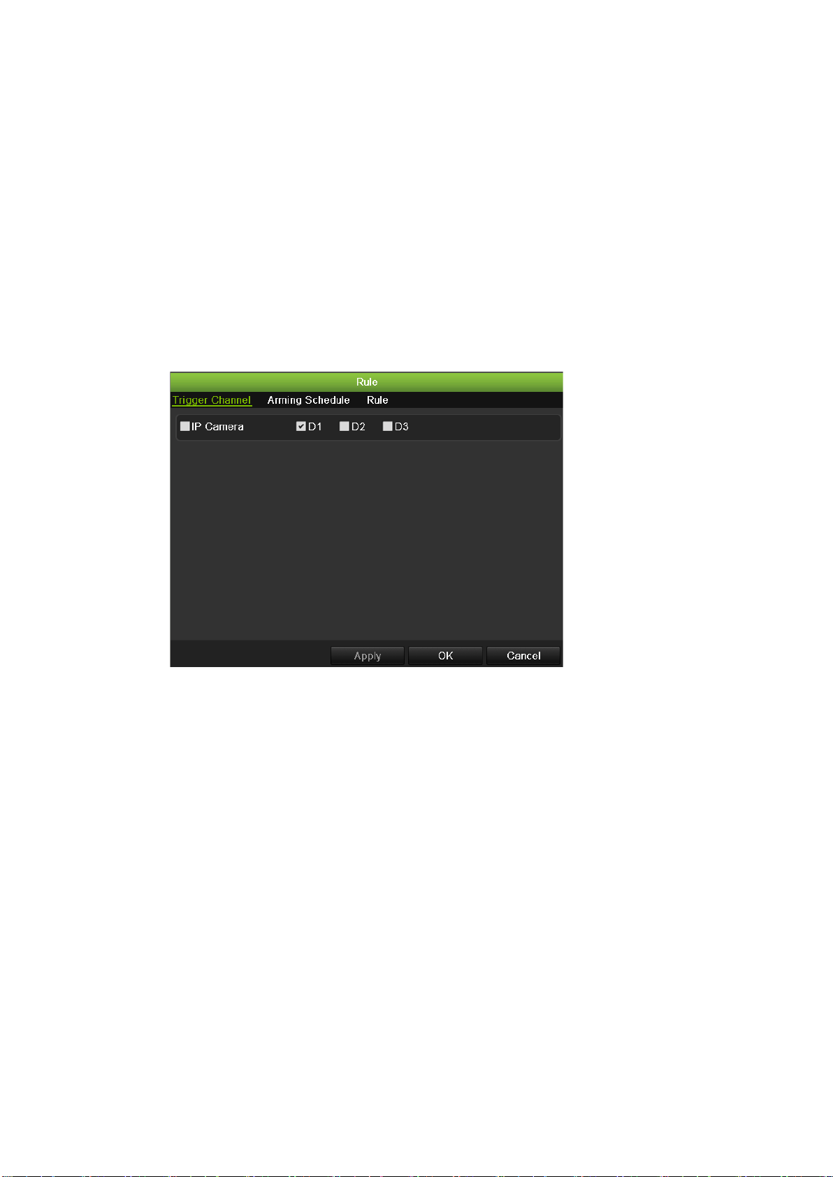
10BChapter 11: Alarm settings
Click and drag the mouse cursor across the screen. The area selected
appears as a red grid. Areas covered by the red grid are sensitive to motion
detection.
Click Full screen to activate the whole screen or Clear to clear the screen.
5. Set the sensitivity level.
Drag the Sensitivity scroll bar to the desired sensitivity level. The highest
value is on the right of the bar.
6. Select the cameras that will record the motion detected.
Click Rule. The Rule screen appears. Click the Trigger Channel tab and
select the cameras that will record when a motion alarm is triggered. Click
Apply to save the settings.
7. Select the recording sc hed ul es for mo ti on det ec ti on.
Click the Arming schedule tab and select the day of the week and the time
periods during the day when motion can be recorded. You can schedule up to
eight time periods in a day. Default is 24 hours.
Click Apply to save the settings. Click Copy to copy the settings to other
days of the week.
Note: Time periods defined cannot overlap.
TruVision NVR 50 User Manual 89
Page 96
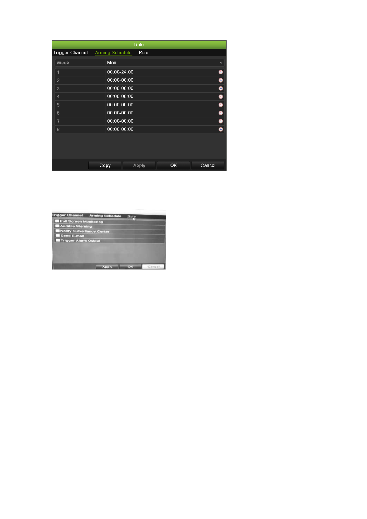
10BChapter 11: Alarm settings
8. Select the response method to motion detection.
Click the Rule tab to define the method by which you want the NVR to notify
you of the alarm. Click Apply to save settings.
9. Click OK to return to the motion detection settings screen.
10. Click Back to return to live view.
Setting up external alarms
The NVR can be configured to record when an alarm is triggered by an external
alarm device (for example, PIR detector, dry contacts, etc.).
90 TruVision NVR 50 User Manual
Page 97
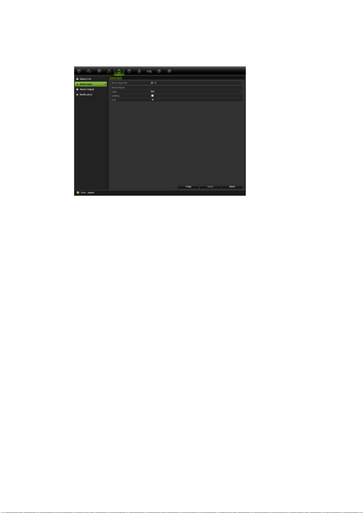
10BChapter 11: Alarm settings
To set up external alarms:
1. Click the Alarm settings icon in the menu toolbar and select Alarm Input.
2. Select the alarm input number of a camera and e nter t he na me o f the in put, if
required.
3. Select the alarm input type, NO or NC.
4. Check the Setting box to enable the func ti o n and cli ck Rule to set up the rules
for the cameras to be tri gg er ed, their alarm schedules, method of alarm
notification and PTZ funct ion.
5. Select the cameras to be triggered when an external alarm is detected.
In the Rule window, click Trigger channel and select the cameras to be
triggered for recording when an alarm is detected. Click Apply to save the
settings.
6. Select the recording schedules for the external alarm.
Click the Arming schedule tab and select the day of the week and the time
periods during the day when motion can be recorded. You can schedule up to
eight time periods in a day. Default is 24 hours.
Click Apply to save the settings. Click Copy to copy the settings to other
days of the week and holiday period.
Note: The time periods defined cannot overlap.
7. Select the response method to an external alarm.
Click the Rule tab to define the method by which you want the NVR to notify
you of the alarm. Click Apply to save settings.
8. Select the PTZ camera function required in response to an external alarm.
Select the PTZ camera and the preset, preset tour or shadow tour that is
triggered when the alarm is detected.
TruVision NVR 50 User Manual 91
Page 98
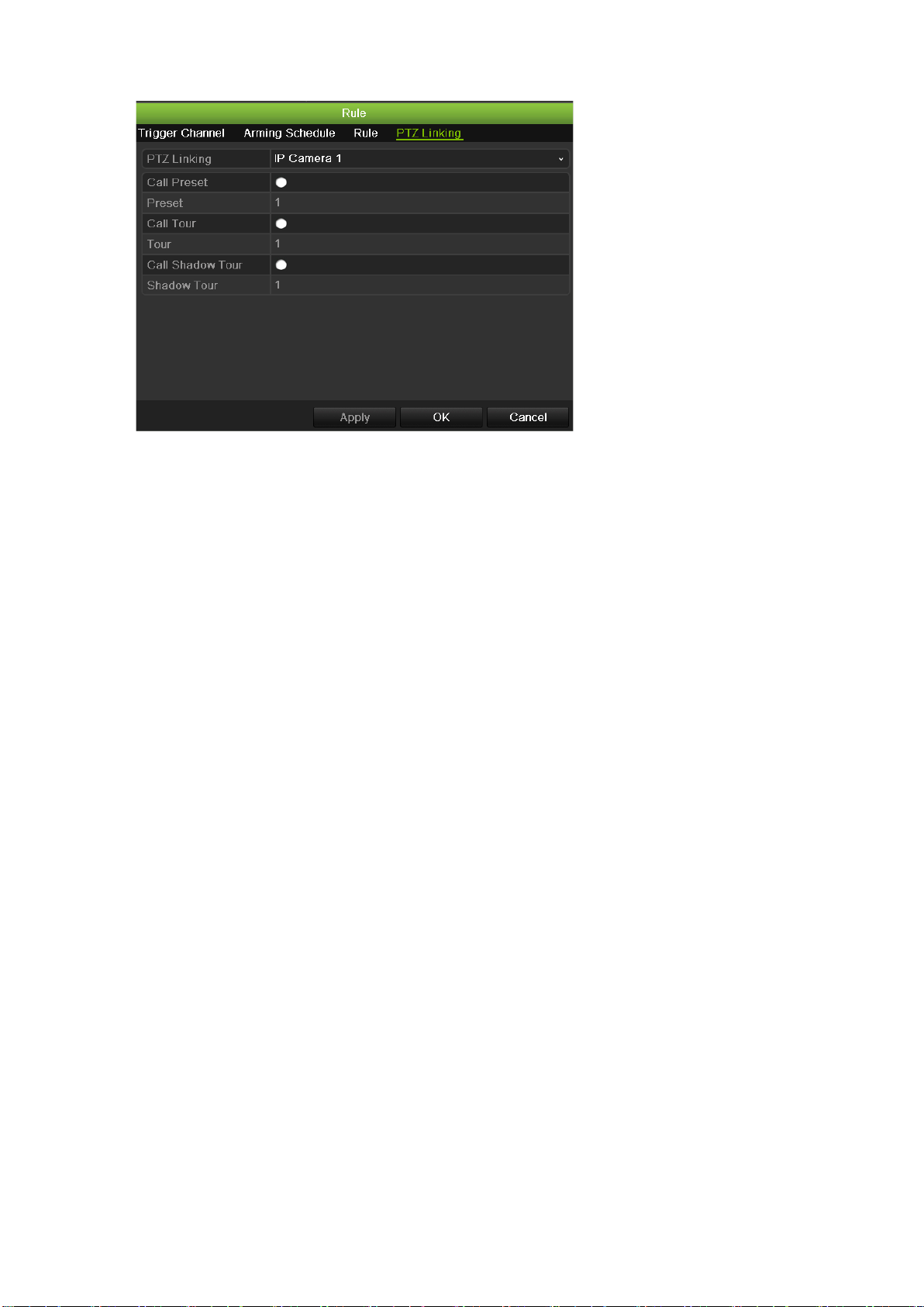
10BChapter 11: Alarm settings
Click Apply to save the settings. Click Copy to copy the settings to other
cameras, if required.
9. Click OK to return to the alarm input screen.
10. Click Back to return to live view.
To set up an alarm output:
Note: Not all IP cameras can be triggered by an alarm output.
1. Click the Alarm Settings icon in the menu toolbar and select Alarm Output.
2. Select the alarm output.
3. Select a timeout option.
The timeout setting lets you define how long a signal remains active after the
alarm has ended. If you select Manually Clear, the signal remains active until
it is manually acknowledged by pressing the alarm button on the front panel
or remote control (see “Triggering or clearing alarm outputs manually” on
page 93).
4. Select the recording schedules for the alarm output.
Click Rule and select the day of the week and the time periods during the day
when motion can be recorded. You can schedule up to eight time periods in a
day. Default is 24 hours.
Click Apply to save the settings. Click Copy to copy the settings to other
days of the week and holiday period.
Note: The time periods defined cannot overlap.
5. Click OK to return to the alarm output screen.
6. Click Back to return to live view.
92 TruVision NVR 50 User Manual
Page 99

10BChapter 11: Alarm settings
Triggering or clearing alarm outputs manually
When an alarm is activated, the NVR can be set up so that the alarm must be
manually acknowledged in order to be silenced. See “Setting up external alarms”
on page 90 for information on setting up an alarm to be manually cleared.
All user levels (administrator, manager and operator) can manually acknowledge
an alarm.
To trigger or clear alarm outputs manually:
1. Click the Alarm settings icon in the menu toolbar and select Alarm Output.
2. Click the Manual Alarm tab.
3. Select the desired alarm output and click one of the following buttons:
• Clear: Clear to stop alarm output.
• Trigger All: Trigger all alarm outputs at once. This action could be done,
for example, when you need to test them.
• Clear All: Stop all alarm outputs at once.
4. Click Back to return to live view. The alarm is s il enc ed.
Setting up system notifications
Setting up system notifications instructs the NVR to alert you when irregular
events occur and how to alert you to the event.
You can quickly check the system status by looking at the status LEDs on the
front panel. When there is an irregular event with the system, an icon appears on
screen to also alert you. See “Status information” on page 27 for further
information.
The system notifications include:
• HDD Full: All installed HDDs are fu ll.
• HDD Error: Errors occurre d while files were being written to the HDD, no
HDD installed or HDD had failed to initialize.
• Network Disconnected: Disconnected network cable.
• IP Conflicted: Conflict in IP address setting.
• Illegal Login: Wrong user ID or password used.
• Abnormal Record: Recording failed due to encoder or HDD problems.
See “Description of alarm notification types” on page 87 for information on the
different alarm notification types available.
TruVision NVR 50 User Manual 93
Page 100

10BChapter 11: Alarm settings
To set up system notifications:
1. Click the Alarm settings icon in the menu toolbar and select Notification.
2. Select a notification type. See “Desc r ipt ion of alarm notificati on types” on
page 87 for more informati o n.
3. Check one or more response options: Audible warning, notify surveillance
center, send e-mail, trigger alarm output.
4. Click Apply to save the settings.
Detecting video loss
Video may be lost if the video cable or camera develop a fault or are damaged.
You can set up the NVR to detect video loss and trigger a system notification.
To setup video loss detection:
1. Click the Camera management icon in the menu toolbar and select Video
Loss.
2. Select a camera to configure for video loss detection.
3. Check the Enable Video Loss Alarm box to enable the feature.
4. Click Rules next to the Video Loss Detection box to enter the Rules screen.
5. Click the Rule tab and select how you want the NVR to notify you of v i deo
loss. Click Apply to save the settings and then clock OK to return to the
previous screen.
6. Click the Arming Schedule tab and select the schedule of when you want
video loss detection to be enabled. Schedule can be set for all week or any
day of the week with up to 8 time periods per day.
7. Click the Apply button to save settings.
8. Click Back to return to live view.
Detecting video tampering
Video tampering, such as moving a camera to a different position, can also be
detected and set to trigger an action on the NVR.
Only IP cameras can be selected. However, not all IP cameras may support this
feature.
Note: It is strongly recommended not to configure for video tampering when
using PTZ dome cameras.
94 TruVision NVR 50 User Manual
 Loading...