

Interlogix TruVision TVB-5702, TruVision TVB-5701, TruVision TVB-5706, TruVision TVB-5707 Configuration Manual
Page 1

TruVision IP Thermal
Camera Configuration
Manual
P/N 1073336-EN • REV C • ISS 21NOV17
Page 2

Copyright
©
2017 United Technologies Corporation.
Interlogix is part of UTC
Climate, Controls & Security
, a unit of United
Technologies Corporation.
All rights reserved.
Trademarks and
patents
T
rade names used in this document may be trademarks or
registered trademarks of the manufacturers or vendors of the
respective products.
Manufacturer
Interlogix
2955 Red Hill Avenue, Costa Mesa, CA 92626
-5923, USA
Authorized EU manufacturing representative:
UTC
Building & Industrial System s B.V.
Kelvinstraat 7, 6003 DH Weert, The Netherlands
Certification
Contact information
For contact information
, see www.interlogix.com or
www.firesecurityproducts.com
.
Page 3

TruVision IP Thermal Camera Configuration Manual 1
Content
Introduction 3
Network access 4
Checking your web browser security level 4
Activating the camera 5
Overview of the camera web browser 7
Camera configuration overview 9
Local configuration menu 9
Configuration menu 11
VCA configuration menu 12
Device information 12
System time configuration 13
Network configuration 14
Video and audio configuration 22
Image display configuration 25
OSD parameters 26
Overlay text parameters 28
Privacy mask parameters 29
Picture overlay parameters 30
Detective pixel correction parameters 30
Alarm configuration 32
Motion detection alarms 32
Video tampering alarms 38
Alarm inputs and outputs 39
Exception alarms 40
Audio exception detect ion 41
Scene change detection 42
Fire source detection 43
Temperature measurement 46
VCA configuration 54
VCA resource type 54
VCA information 54
Behavior analysis 56
Storage configuration 62
Snapshot parameters 62
NAS settings 65
Storage management 66
Recording schedule 67
Page 4

2 TruVision IP Thermal Camera Configuration Manual
Camera management 69
User management 69
RTSP authentication 72
IP address filter 73
Defining the security service 73
Restore default settings 74
Import/export a configuration file 75
Upgrade firmware 75
Reboot the camera 76
Camera operation 78
Logging on and off 78
Live view mode 78
Playing back recorded video 78
Searching event logs 81
Operating PTZ control 83
Page 5

TruVision IP Thermal Camera Configuration Manual 3
Introduction
This is the user manual for the following TruVision IP thermal camera models:
TVB-5701 (IP Thermal Bullet Camera, 384x288, 15mm)
TVB-5702 (IP Thermal Bullet Camera, 384x288, 35mm)
TVB-5706 (IP Thermal Bullet Camera, 640x512, 15mm)
TVB-5707 (IP Thermal Bullet Camera, 640x512, 25mm)
Page 6

4 TruVision IP Thermal Camera Configuration Manual
Network access
This manual explains how to configure the camera over the network with a web
browser.
TruVision IP cameras can be configured and controlled using Microsoft Internet
Explorer (IE) and other browsers. The procedures described use Microsoft Internet
Explorer (IE) web browser.
Checking your web browser security level
When using the web browser interface, you can install ActiveX controls to connect and
view video using Internet Explorer. However, you cannot download data, such as video
and images, due to the increased security measure. Consequently you should check
the security level of your PC so that you are able to interact with the cameras over the
web and, if necessary, modify the Active X settings.
Configuring IE ActiveX controls
You should confirm the ActiveX settings of your web browser.
To change the web browser’s security level:
1. In Internet Explorer, click Internet Options on the Tools menu.
2. On the Security tab, click the zone to which you want to assign a web site und er
“Select a web content zone to specify its security settings”.
3. Click Custom Level.
4. Change the ActiveX controls and plug-ins options that are signed or marked as
safe to Enable. Change the ActiveX controls and plug-ins options that are
unsigned to Prompt or Disable. Click OK.
- Or Under Reset Custom Settings, click the security level for the whole zone in the
Reset To box, and select Medium. Click Reset.
Then click OK to the Internet Options Security tab window.
5. Click Apply in the Internet Options Security tab window.
Windows Internet Explorer
Internet Explorer operating systems have increased security measures to protect your
PC from any malicious software being installed.
To have complete functionality of the web browser interface with Windows 7, 8, and 10,
do the following:
• Run the browser interface as an administrator in your workstation
• Add the camera’s IP address to your browser’s list of trusted sites
Page 7
TruVision IP Thermal Camera Configuration Manual 5
To add the camera’s IP address to Internet Explorer’s list of trusted sites:
1. Open Internet Explorer.
2. Click Tools, and then Internet Options.
3. Click th e Security tab, and then select the Trusted sites icon.
4. Click th e Sites button.
5. Clear the “Require server verification (https:) for all sites in this zone box.
6. Enter the IP address in the “Add this website to the zone” field.
7. Click Add, and then click Close.
8. Click OK in the Internet Options dialog window.
9. Connect to the camera for full browser functionality.
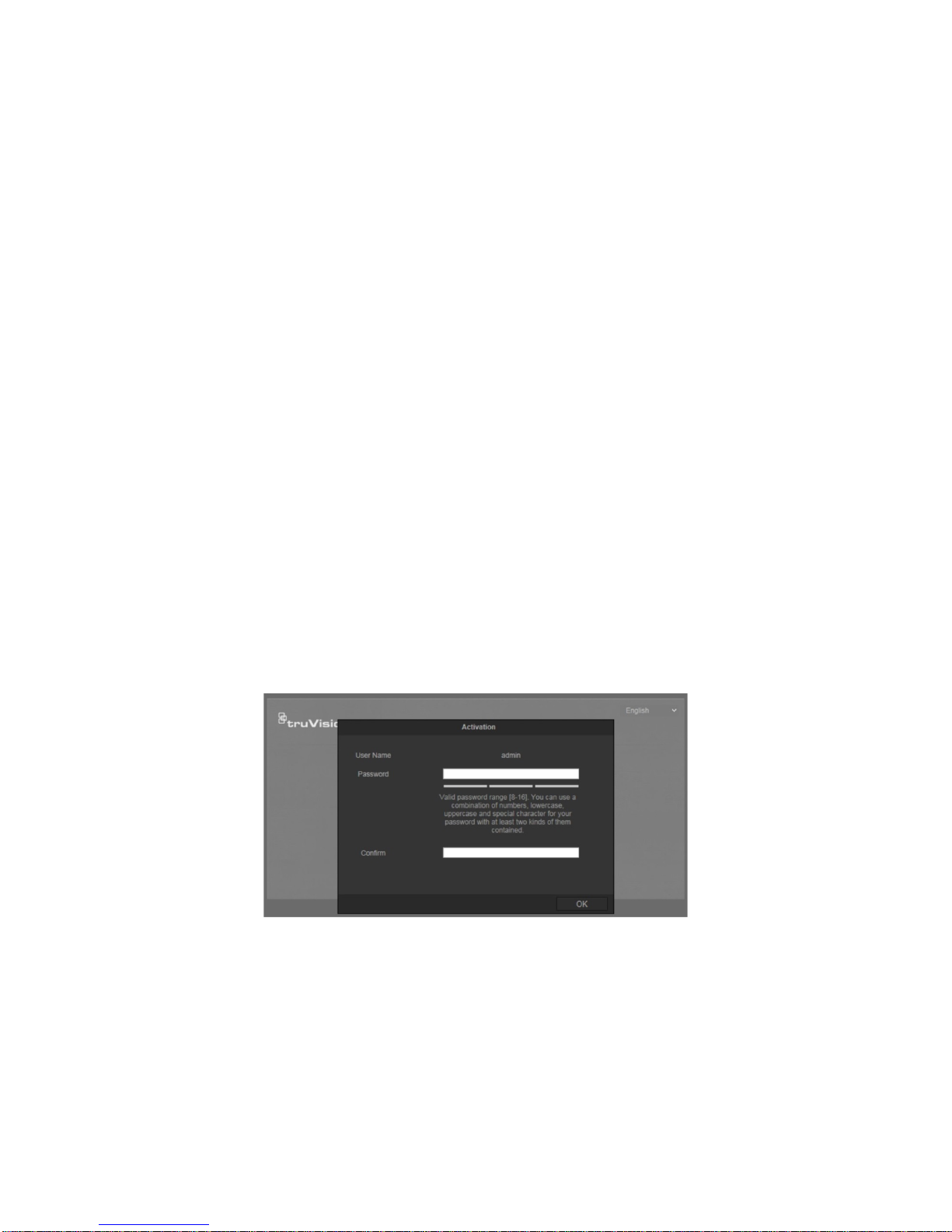
Activating the camera
When you fi r st start up the camera, the Activation window appears. You must define a
high-security admin password before you can access the camera. There is no default
password provided.
You can activate a password by using a web browser and by TruVision Device
Manager (included on the CD to find the IP address of the camera).
Activation via the web browser:
1. Power on the camera and connect the camera to the network.
2. Input the IP address into the address bar of the web browser, and click Enter to
enter the activation interface.
Note:
The default IP address of the camera is 192.168.1.70.
For the camera to enable DHCP by default, you must activate the camera via
TruVision Device Manager. Please refer to the following section, “Activation via
TruVision Device Manager”.
3. Enter the password in the password field.
Page 8

6 TruVision IP Thermal Camera Configuration Manual
Note: A valid password range must be between 8 and 16 characters. You can use a
combination of numbers, lower and upper case letters, and special characters : _ - ,
. * & @ / $ ? Space. The password must contain characters from at least two of
these groups. We also recommend that you reset your password regularly. For high
security systems, it is particularly recommended to reset the password monthly or
weekly for better protection.
4. Confirm the password.
5. Click OK to save the password and enter the live view interface.
Activation via TruVision Device Manager:
1. Run the TruVision Device Manager to search for online devices.
2. Select the device status from the device list, and select the inactive device.
3. Enter the password in the password field, and confirm it.
Note: A valid password range must be between 8 and 16 characters. You can use a
combination of numbers, lower and upper case letters, and special characters : _ - ,
. * & @ / $ ? Space. The password must contain characters from at least two of
these groups. We also recommend that you reset your password regularly. For high
security systems, it is particularly recommended to reset the password monthly or
weekly for better protection.
4. Click OK to save the password.
A pop-up window appears to confirm activation. If activation fails, confirm that the
password meets the requirements and try again.
5. Change the device IP address to the same subnet with your computer by either
modifying the IP address manually or selecting the check box of Enable DHCP.
Page 9
TruVision IP Thermal Camera Configuration Manual 7
6. Enter the password and click the Save button to activate your IP address
modification.
Overview of the camera web browser
The camera web browser lets you view, record, and play back recorded videos as well
as manage the camera from any PC with Internet access. The browser’s easy-to-use
controls give you quick access to all camera functions. See Figure 1.
If there is more than one camera connected over the network, open a separate web
browser window for each individual camera.
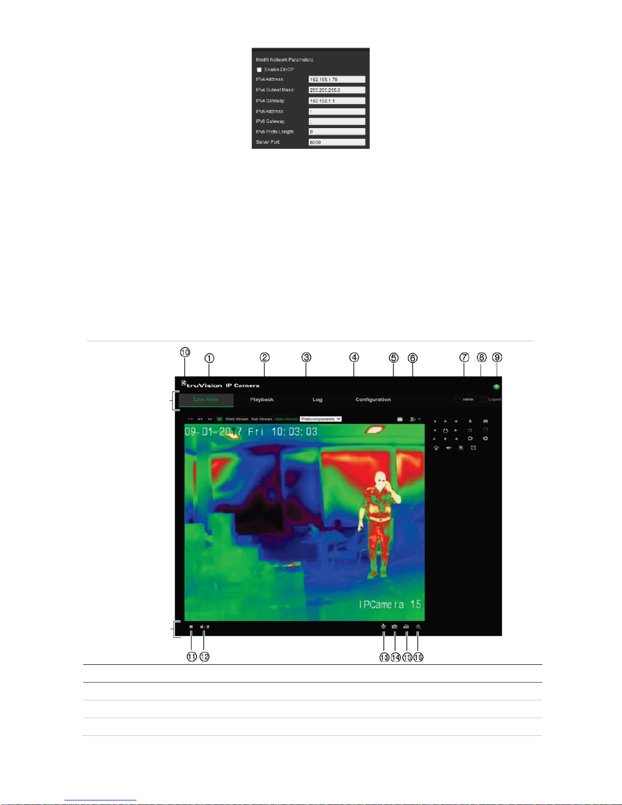
Figure 1: Web browser interface (Live view shown)
Menu bar
Toolbar
Name
Description
1. Live view Click to view live video.
2. Playback Click to play back video.
3. Log Click to search for event logs. There are three main types: Alarm, Exception and
Page 10
8 TruVision IP Thermal Camera Configuration Manual
Name
Description
Operation.
4. Configuration Click to display the configuration window for setting up the camera.
5. Viewer View live video. Time, date and camera name are displayed here.
6. PTZ controls Direction actions, zoom, focus, iris, light and wiper control. See page 83 for
further information.
Note: Direction actions, light, and wiper control can be used if the camera
supports RS-485 and the external pan/tilt unit, light or wiper is installed.
7. Current user Displays current user logged on.
8. Logout Click to log out from the system. This can be done at any time.
9. Help Online Help.
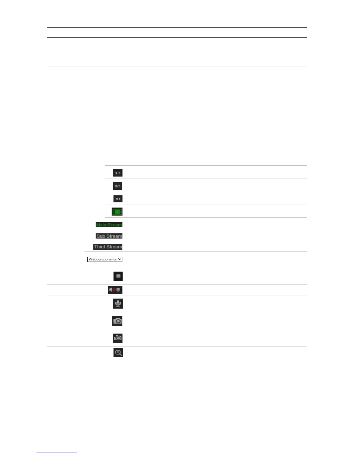
10. Display control Click each tab to adjust the layout and the stream type of the live view. You can
also click the drop-down menu to select the plug-in.
For IE (internet explorer) users, web components and quick time are selectable.
For non-IE users, we b components, quick time, VLC or MJPEG are s elec tab le if
they are supported by the web browser.
The window size is 4:3.
The window size is 16:9.
The original window size.
Self-adaptive window size.
Live view with main stream.
Live view with substream.
Live view with third stream.
Click to select the third-party plug-in. Select Webcomponents or
QuickTime.
11. Start/stop live
view
Click to start/stop live view.
12. Audio
Click to turn audio on/off. Also use the scroll bar to adjust the volume.
13. Bi-directional
audio
Turn on/off the microphone for bidirectional audio.
14. Capture
Click to capture a snapshot of the video. The snapshot will be saved to
the default folder in JPEG or BMP format.
15. Start/stop
recording
Click to manually start/stop recording of live video.
16. Digital zoom
Click to enable digital zoom.
Page 11
TruVision IP Thermal Camera Configuration Manual 9
Camera configuration overview
Once the camera hardware has been installed, configure the camera’s settings through
the web browser. You must have administrator rights to configure the cameras over the
internet.
The camera web browser lets you configure the camera remotely using your PC. Web
browser options may vary depending on the camera model.
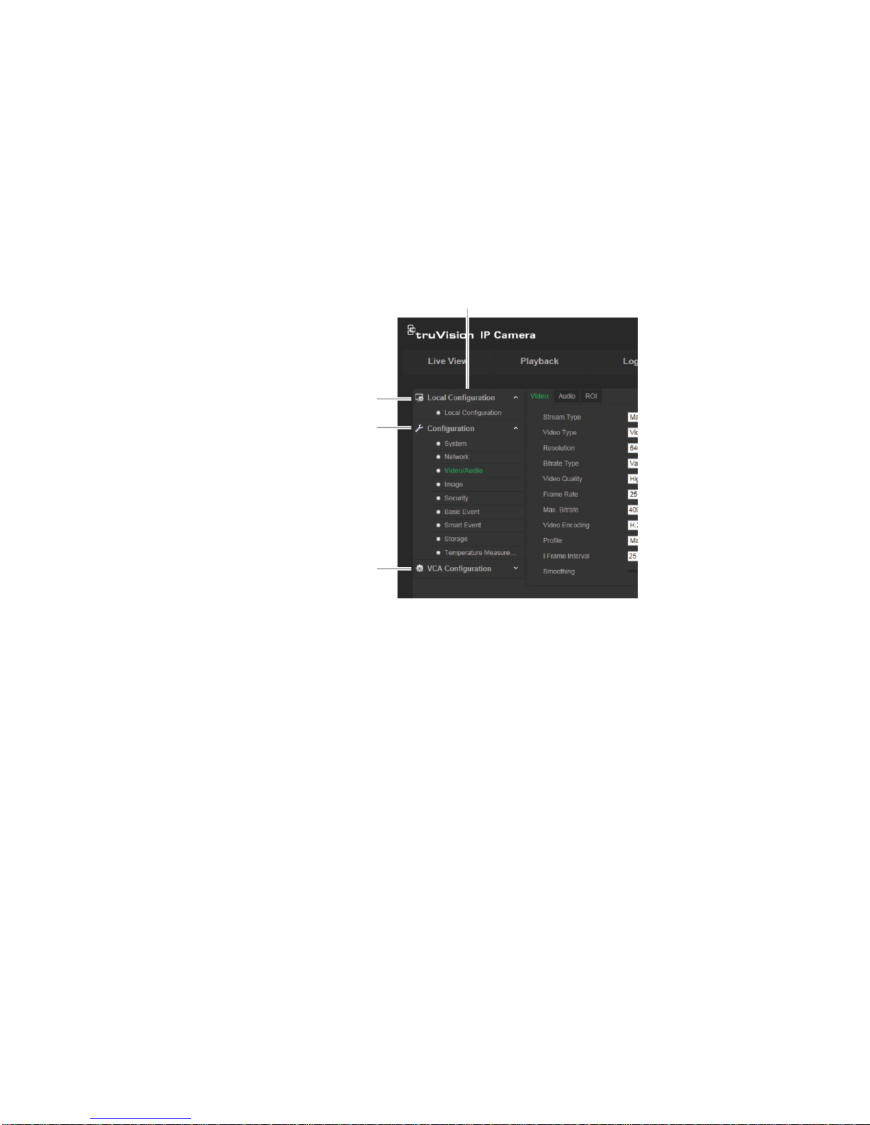
There are three main menus in the configuration panel:
Configuration panel
Local configuration. See below for
more information.
Configuration. See “Configuration
menu” on page 11 for more information.
VCA configuration. See “VCA
configuration” on page 12 for more
information.
Local configuration menu
Use the Local configuration me nu t o manage the protocol type, live view parameters
and local storage paths. In the Configuration panel, click Local Configuration to
display the local configuration window. See Figure 2 below for descriptions of the
different menu parame ter s.
Page 12

10 TruVision IP Thermal Camera Configuration Manual
Figure 2: Local configuration window
Description
Live View Parameters
1.
Protocol
Specifies the network protocol used.
Select TCP, UDP, MULTICAST, or HTTP.
2.
Live View Performance
Specifies the transmission speed.
Select Shortest Dela y or Auto.
3.
Rules
These are the rules on your local browser.
Specifies whether or not to display the colored marks when motion
detection, face detection, and intrusion detection are triggered. For
example, when the rules option is enabled and a face is detected, the
face will be marked with a green rectangle in live view.
4.
Image Format
Choose the image format for a snapshot: JPEG or BMP.
5.
Display Temperature info
Specifies whether or not to display the temperature inf ormation on
Live View.
Select Enable or Disable.
6.
Display Temperature info
on Capture
Specifies whether or not to display the temperature info on the
Captured image.
Select Enable or Disable.
Record File Settings
7.
Record F
ile Size Specifies the maximum file size.
Select 256 MB, 512 MB, or 1G.
8.
Save
Record Files to Specifies the directory for recorded files.
Page 13
TruVision IP Thermal Camera Configuration Manual 11
Description
9.
Save
Downloaded Files to Specifies the directory for downloaded files.
Snapshot and Clip Settings
10.
Save
Snapshots In Live
View To
Specifies the directory for saving snapshots in live view mode.
11.
Save
Snapshots When
Playback To
Specifies the directory for saving snapshots in playback mode.
12.
Save Clips To
Specifies the directory for saving video clips in playback mode.
Configuration men u
Use the Configuration panel to configure the server, network, camera, alarms, users,
transactions and other par a meters such as upgrading the firmw ar e. See Figure 3 below
for descriptions of the configuration menus available.
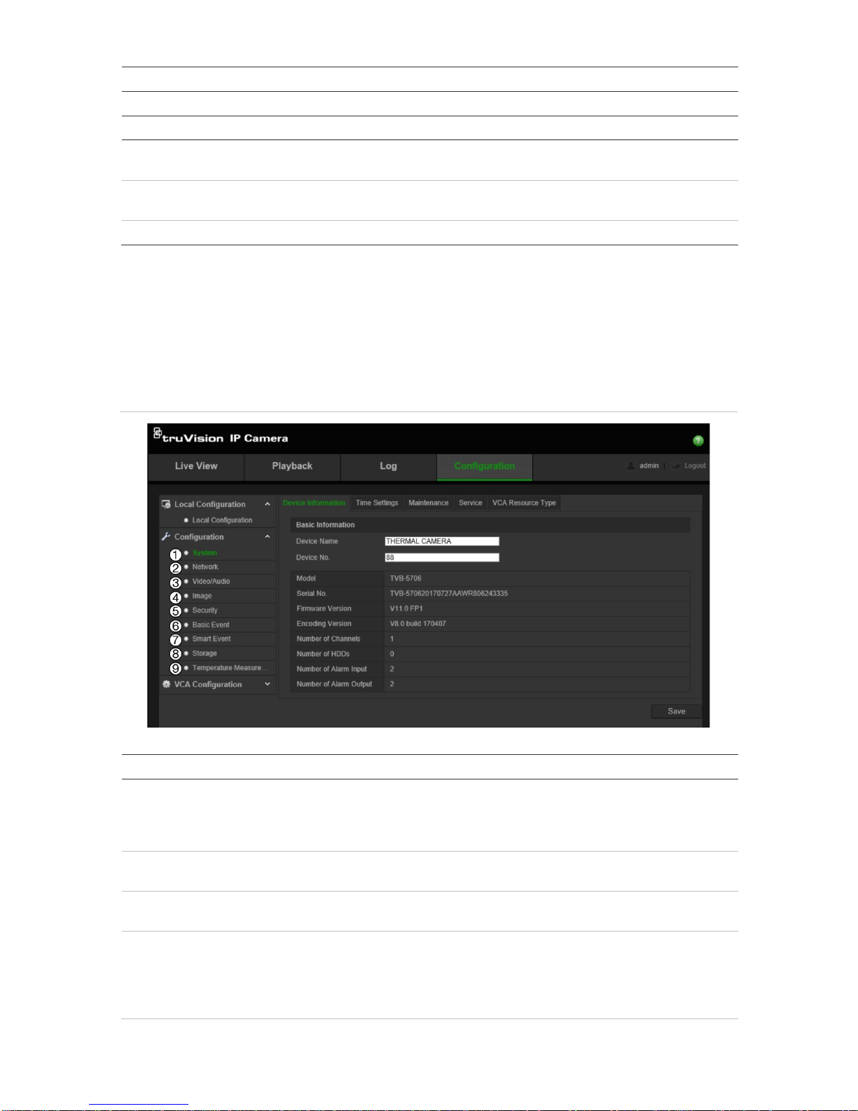
Figure 3: Configuration window (‘System > Device Information’ shown)
Configuration menus Description
1.
System
Defines device basic information including SN and the current firmware
version, time settings, maintenance, serial port parameters, and VCA resource
type. See “System time configuration” on page 12 for further information on
time parameters.
2.
Network
Defines the network parameters required to access the camera over the
internet. See “Network configuration” on page 14 for further information.
3.
Video/Audio
Defines recording parameters. See “Video and audio ” on page 22 for further
information.
4.
Image
Defines the image parameters, OSD settings, overlay text, privacy masking,
picture overlay, and defective pixe l correc tio n. See “Image” on page 25, “OSD
”
on page 26, “Overlay text” on page 28, “Privacy mask” on page 29, “Picture
overlay” on page 30, and “Defective pixel correction” on page 30 for further
information.
Page 14

12 TruVision IP Thermal Camera Configuration Manual
Configuration menus Description
5.
Security
Defines who can use the camera, their passwords and access privileges,
RTSP authentication, IP address filter, SSH access, restoring default settings,
firmware upgrade. See “User management” on page 69, “RTSP
authentication” on page 72, “IP address filter” on page 73, “Defining the
security service” on page 73, and “Restore default settings” on page 74 for
further information.
6.
Basic
Event Defines motion detection, video tampering, alarm input/output, and exception.
You can also import/export configuration files. See “Motion detection alarms”
on page 30, “Video tam pering alarms” on page 38, “Alarm inputs and out puts”
on page 39, “Exception alarms” on page 40, and “Import/export a configuration
file” on page 75 for further information.
7.
Smart Event
Defines audio exception detection, scene change detection, and fire source
detection. See “Audio exception detection” on page 41” on page 40, “Scene
change detection” on page 42, and “Fire source detection” on page 43 for
further information.
8.
Storage
Defines recording schedule, storage management, NAS configuration, and
snapshot parameters. See Snapshot parameters” on page 54, “NAS settings”
on page 65, “Storage ” on page 66, and “Recording schedule” on page 67 for
further information.
9.
Temperature
Measurement
Defines temperature measurement and temperature measurement and alarm.
See “Temperature measurement” on page 46 for further information.
VCA configuration menu
Use the VCA Configuration panel to configure how target and rule information is
displayed on a snapshot and in a video stream, the snapshot quality and resolution, as
well as set up the response to suspicious behavior. See “VCA information” on page 54
and “Behavior analysis” on page 56 for more information.
Device information
You can quickly see the information about the camera as well as change the camera
name and device number. See Figure 3 on page 11 for descriptions of the configuration
menus available.
To display the camera device information:
1. From the Configuration panel, click Configuration > System > Device
Information.
2. If desired, you can change the camera name and device number.
3. Click Save to save changes.
Page 15
TruVision IP Thermal Camera Configuration Manual 13
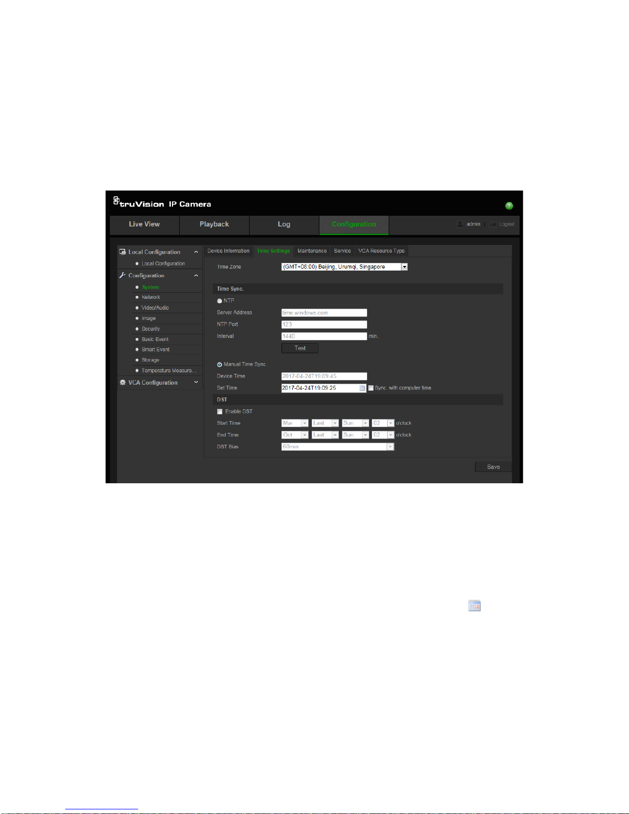
System time configuration
NTP (Network Time Protocol) is a protocol for synchronizing the clocks of network
devices, such as IP cameras and computers. Connecting network devices to a
dedicated NTP time server ensures that they are all synchronized.
To define the system time and date:
1. From the Configuration panel, click Configuration > System > Time Settings.
2. From the Time Zone drop-down menu, select the time zone that is the closest to the
camera’s location.
3. Under Time Sync, select one of the options for setting the ti me and date:
Synchronize with an NTP server: Select the NTP enable box and enter the server
NTP address. The time interval can be set from 1 to 10080 minutes.
- Or Set manually: Enabl e the Manual Time Sync function and then click to set the
system time from the pop-up calendar.
Note: You can also select the Sync with computer time check box to synchronize
the time of the camera with the time of your computer.
4. Select Enable DST to enable the DST (Daylight Savings Time) function, and set the
date of the DST period.
5. Click Save to save changes.
Page 16
14 TruVision IP Thermal Camera Configuration Manual
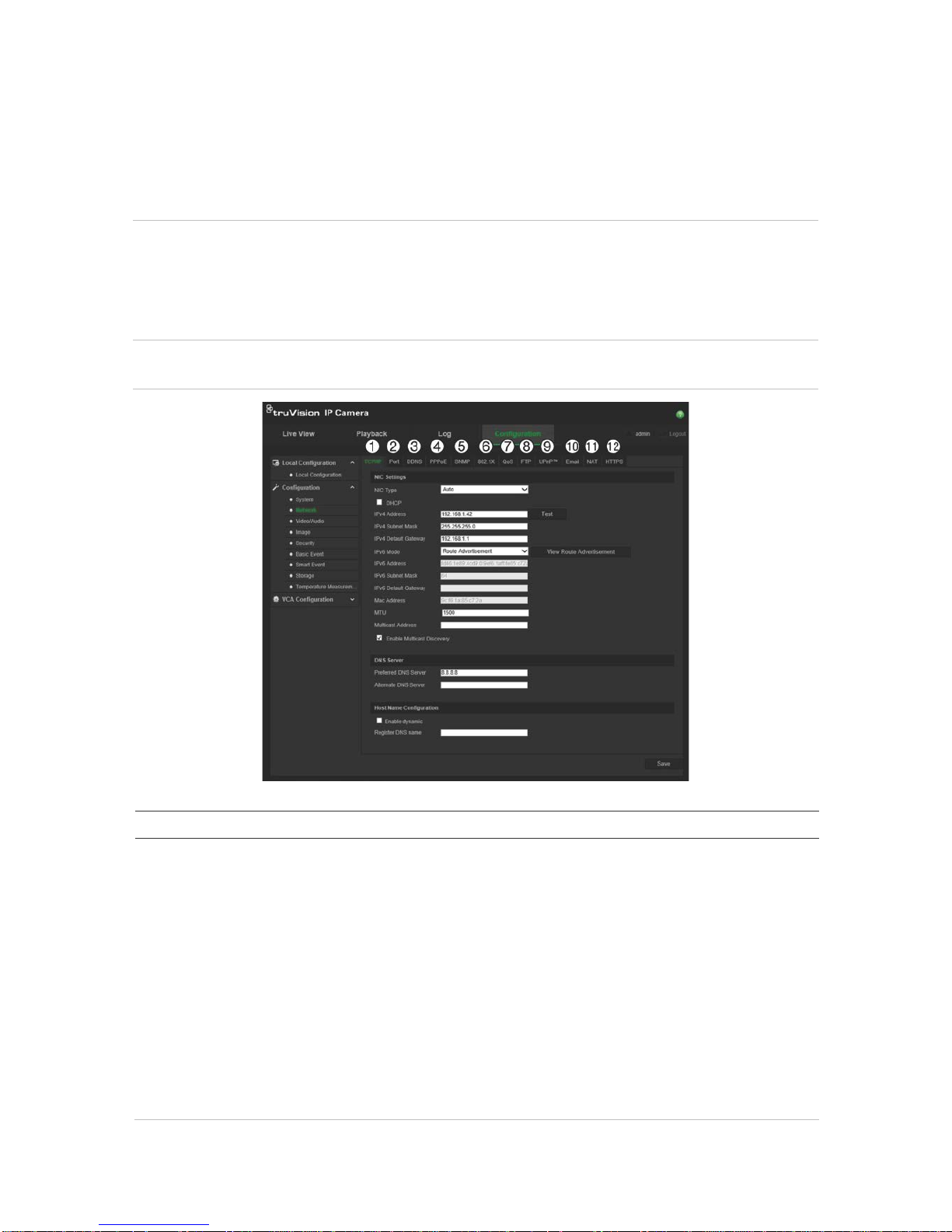
Network configuration
You need to define the network settings to be able to access the camera through a
network. Use the “Network” menu to define the network settings. See Figure 4 below for
further information.
Caution: We strongly recommend that you use a strong password for all functions and
network devices in order to protect your privacy and to protect your system against
security risks. A valid password range must be at least eight characters. You can use a
combination of numbers, lower and upper case letters, and special characters. The
installer and/or end user are responsible for password management.
Figure 4: Network window (TCP/IP tab shown)
Menu tabs Description
1.
TCP/IP
NIC Type: Enter the NIC type. Default is Auto. Other options include: 10M Half-
dup, 10M Full-dup, 100M Half-dup and 100M Full-dup.
DHCP: Enable in order to automatically obtain an IP address and other network
settings from that server.
IPv4 Address: Enter the IPv4 address of the camera.
IPv4 Subnet Mask: Enter the IPv4 subnet mask.
IPv4 Default Gateway: Enter the IPv4 gateway IP address.
IPv6 Mode: Enter the IPv6 mode: Manual, DHC P, or R oute Ad vertisement.
IPv6 Address: Enter the IPv6 address of the camera.
IPv6 Subnet Prefix Length: Enter the IPv6 prefix length.
IPv6 Default Gateway: Enter the IPv6 gateway IP address.
Mac Address: Enter the MAC address of the devices.
MTU: Enter the valid value range of MTU. Default is 1500.
Page 17

TruVision IP Thermal Camera Configuration Manual 15
Menu tabs Description
Multicast Address: Enter a D-class IP address between 224.0.0.0 to
239.255.255.255. Only specify this option if you are using the multicast function.
Some routers prohibit the use of multicast function in case of a network storm.
Enable Multicast Discovery: Select to enable the automatic detection of the
online network camera via private multicast protocol in the LAN.
DNS server: Enter the DNS server address f or your netw ork.
Host Name Configuration: Assign a hostname to rec
order to be used to identify
it over the network. Select “Enable dynamic” and enter your DNS name for the
system. The DNS name must be unique and can contain letters, numbers and
hyphens.
2.
Port
HTTP Port: Use the HTTP port to remotely access the internet bro wser . Enter
the port used for the Internet Explorer (IE) browser. Default value is 80.
RTSP Port: RTSP (Real Time Streaming Protocol) is a network control protocol
designed for use in entertainment and communications systems to control
streaming media servers. Enter the RTSP port value. The default port number is
554.
HTTPS Port: HTTPS (Hyper Text Transfer Protocol Secure) allows video to be
securely viewed when using a browser. Enter the HTTPS port, value. The
default port number is 443.
Server Port: This is used for remote client software access. Enter the server
port value. The default port number is 8000.
Alarm Server IP: Specifies the IP address of the alarm host.
Alarm Server Port: Specifies the port of the alarm host.
See page 17 for setup information.
3.
DDNS
DDNS is a service that maps Internet domain names to IP addresses. It is
designed to support dynamic IP addresses, such as those assigned by a DHCP
server.
Specify DynDNS or ezDDNS.
DynDNS: Use Dynamic DNS to manually create your own host name. You will
first need to create a user account using the hosting web site, DynDDNS.org.
ezDDNS: Activate the DDNS auto-detection function to set up a dynamic IP
address. The server is set up to assign an available host name to your recorder.
See page 17 for setup information.
4.
PPPoE
Retrieves a dynamic IP address. See page 17 for setup information.
5.
SNMP
SNMP is a protocol for managing devices on networks. Enable the SNMP check
box to get camera status and parameter related information. See page 17 for
setup information.
6.
802.1.X
When the feature is enabled, the camera data is secured and user
authentication is needed when connecting the camera to the network. See page
18 for setup information.
7.
QoS
QoS (Quality of Service) can help solve the network delay and network
congestion by configuring the priority of data sending.
Enable the option to solve network delay and network congestion by configuring
the priority of data sending.
See page 18 for setup information.
8.
FTP
Enter the FTP address and folder to which snapshots of the camera can be
uploaded. See page 18 f or s etup inf ormation.
Page 18

16 TruVision IP Thermal Camera Configuration Manual
Menu tabs Description
9.
UPnP
The UPnP (Universal Plug and Play) protocol allows devices to connect
seamlessly and to simplify the implementation of networks in the home and
corporate environments. With the function enabled, you do not need to configure
the port mapping for each port, and the camera is connected to the Wide Area
Network (WAN) via the router.
Enable and set the friendly name detected.
See page 18 for setup information.
10.
Email
Enter the email address to which messages are sent when an alarm occurs.
See
page 18 for setup information.
11.
NAT
A NAT (Network Address Translation) is used for network connection. Select the
port mapping mode: auto or manual. See page 20 for setup inform ation.
12.
HTTPS
Specifies authentication of the web site and its associated web server, which
protects against Man-in-the-middle attacks .
To define the TCP/IP parameters:
1. From the Configuration panel, click Configuration > Network > TCP/IP.
2. Configure the NIC settings, including the NIC Type, IPv4 settings, IPv6 settings,
MTU settings, and Multicast Address.
3. If the DHCP server is available, select DHCP.
4. If the DNS server settings are required for some applications (e.g., sending email),
you should configur e t he Preferred DNS Server or Alternate DNS Server.
5. To be able to automatically detect the network camera by client software, select
Enable Multicast Discovery. This step is optional.
6. Click Save to save changes.
To define the port parameters:
1. From the Configuration panel, click Configuration > Network > Port.
2. Set the HTTP port, RTSP port, HTTPS port and server port of the camera.
HTTP Port: The default port number is 80, and it can be changed to any port No.
which is not occupied.
RTSP Port: The default port number is 554. It can be changed to any port number
in the range from 1 to 65535.
HTTPS Port: The default port number is 443. It can be changed to any port number
that is not occupied.
Server Port: The default server port number is 8000. It can be changed to any port
number in the range from 2000 to 65535.
3. Enter the IP address and port if you want to upload the alarm information to the
remote alarm host. Also select the Notify Alarm Recipient option in the normal
Linkage of each event page.
4. Click Save to save changes.
Page 19

TruVision IP Thermal Camera Configuration Manual 17
To define the DDNS parameters:
If the camera is set up to use PPPoE as its default network connection, you can use
Dynamic DNS (DDNS) for network access. You need to register on the DDNS server
before you can configure the settings.
1. From the Configuration panel, click Configuration > Network > DDNS.
2. Select Enable DDNS to enable this feature.
3. Select the DDNS Type. There are two options available: DynDNS and ezDDNS.
• DynDNS: Enter the DDNS server address, members.ddns.org (which is used to
notify DDNS about changes to your IP address), the host name for your ca mera,
the port number (443 (HTTPS), and your user name and password used to log
into your DDNS account. The domain name displayed under “Host Name” is that
which you created on the DynDNS web site.
• ezDDNS: Enter the desired host name under “Host Name”. The default host
name is utc-serial number. The new host name is registered when you click
Save.
Note: The default server address is www.tvr-ddns.net, which cannot be changed.
4. Click Save to save changes.
To define the PPPoE parameters:
1. From the Configuration panel, click Configuration > Network > PPPoE.
2. Select Enable PPPoE to enable this feature.
3. Enter the user name, password, and confirm the password for PPPoE access.
4. Click Save to save changes.
To define the SNMP parameters:
1. From the Configuration panel, click Configuration > Network > SNMP.
2. Select the corresponding version of SNMP: v1, v2c or v3.
3. Configure the SNMP settings. The configuration of the SNMP software should be
the same as the settings you configure here.
4. Click Save to save changes.
Note: Before setting the SNMP, please download the SNMP software to receive the
camera information via the SNMP port. By setting the trap address, the camera can
send the alarm event and exception messages to the surveillance center. The SNMP
version you select should be the same as that of the SNMP software. The security level
of the software depends on its version. SNMP v1 has no security. SNMP v2 requires a
password for access. SNMP v3 provides encryption. If you use SNMP v3, you must
enable HTTPS.
Page 20

18 TruVision IP Thermal Camera Configuration Manual
To define the 802.1x parameters:
1. From the Configuration panel, click Configuration > Network > 802.1X.
2. Select Enable IEEE 802 .1X to enable the feature.
3. Configure the 802.1X settings, including EAPOL version, user name, and password.
The EAPOL version must be identical with that of the router or the switch.
4. Click Save to save changes.
Note: The switch or router to which the camera is connected must also support the
IEEE 802.1X standard, and a server must be configured. Please apply and register a
user name and password for 802.1X in the server.
To define the QoS parameters:
1. From the Configuration panel, click Configuration > Network > QoS.
2. Configure the QoS settings, including Video / Audio DSCP, Ev ent / Alarm DSCP
and Management DSCP. The valid value range of the DSCP is 0 to 63. The larger
the DSCP value, the higher the priority.
3. Click Save to save changes.
Note: The system needs to be rebooted in order for the changes to take effect.
To define the FTP parameters:
1. From the Configuration panel, click Configuration > Network > FTP.
2. Configure the FTP settings, including server address, port, user name, password,
directory, and upload type.
Anonymous: Select the check box to enable the anonymous access to the FTP
server.
Directory: In the Directory Structure field, select the root directory, main directory
and subdirectory. When the Main directory is selected, select the Device Name,
Device Number or Device IP for the name of the directory. When the S ubdirector y is
selected, select the Camera Name or Camera No. as the name of the directory.
Upload Type: To enable snapshots to be uploaded to the FTP server.
3. Click Save to save changes.
To define the UPnP parameters:
1. Click Configuration > Network > UPnP.
2. Select the check box to enable the UPnP fun ct ion. The name of the detected device
appears under “Friendly name”. It can be edited.
3. Click Save to save changes.
To set up the email parameters:
1. From the Configuration panel, click Configuration > Network > Email.
Page 21
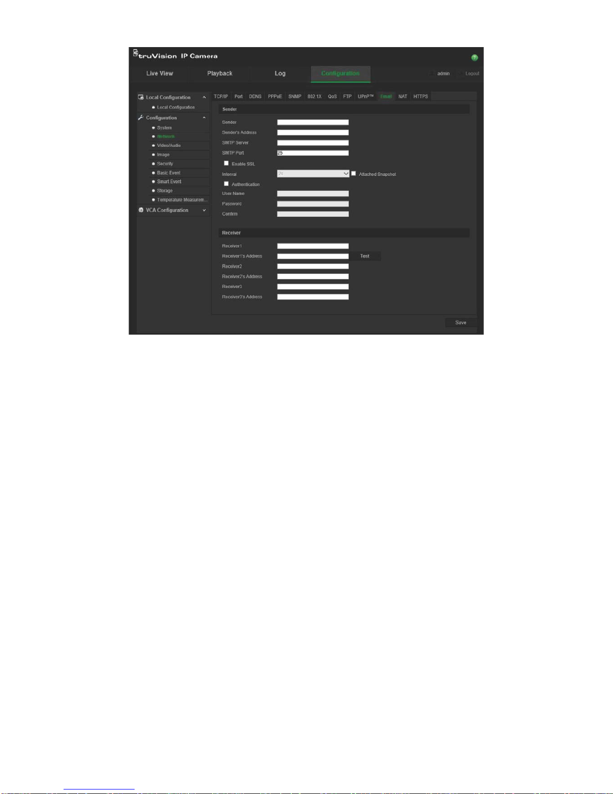
TruVision IP Thermal Camera Configuration Manual 19
2. Configure the following settings:
Sender: The name of the email sender.
Sender’s Address: The email address of the sender.
SMTP Server: The SMTP Server, IP address or host name.
SMTP Port: The SMTP port. The default is 25.
Enable SSL: Select the check box to ena bl e SSL i f it is required by the SMTP
server.
Interval: This is the time between two actions to send attached snapshots.
Attached Snapshot: Select the Attached Snapshot check box if you want to send
emails with attached alarm images.
Authentication: If your email server requires authentication, select this check box
to use authentication to log in to this server. Enter the login user name and
password.
User Name: The user name to log in to the server where the images are uploaded.
Password: Enter the password.
Confirm: Confirm the password.
Receiver1: The name of the first user to be notified.
Receiver’s Address1: The email address of the user to be notified. Click Test to
test the address.
Receiver2: The name of the second user to be noti fied.
Receiver’s Address2: The email address of the user to be notified.
Page 22
20 TruVision IP Thermal Camera Configuration Manual
Receiver3: The name of the third user to be notified.
Receiver’s Address3: The email address of the user to be notified.
3. Click Test to test the email parameters set up.
4. Click Save to save changes.
To set up the NAT parameters:
1. From the Configuration panel, click Configuration > Network > NAT.
2. Select the check box t o enabl e the NAT function.
3. Select Port Mapping Mode to be Auto or Manual. When you select Manual mode,
you can set any desired external port.
4. Click Save to save changes.
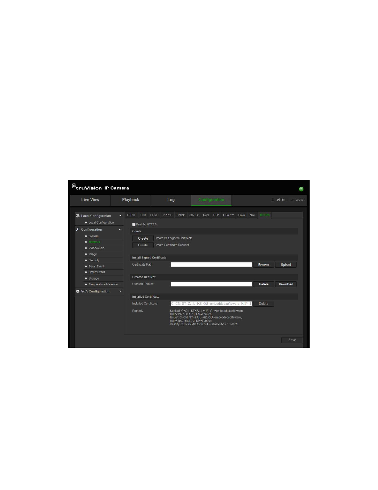
To set up the HTTPS parameters:
1. From the Configuration panel, click Configuration > Network > HTTPS.
2. Create a self-signed cert if icate:
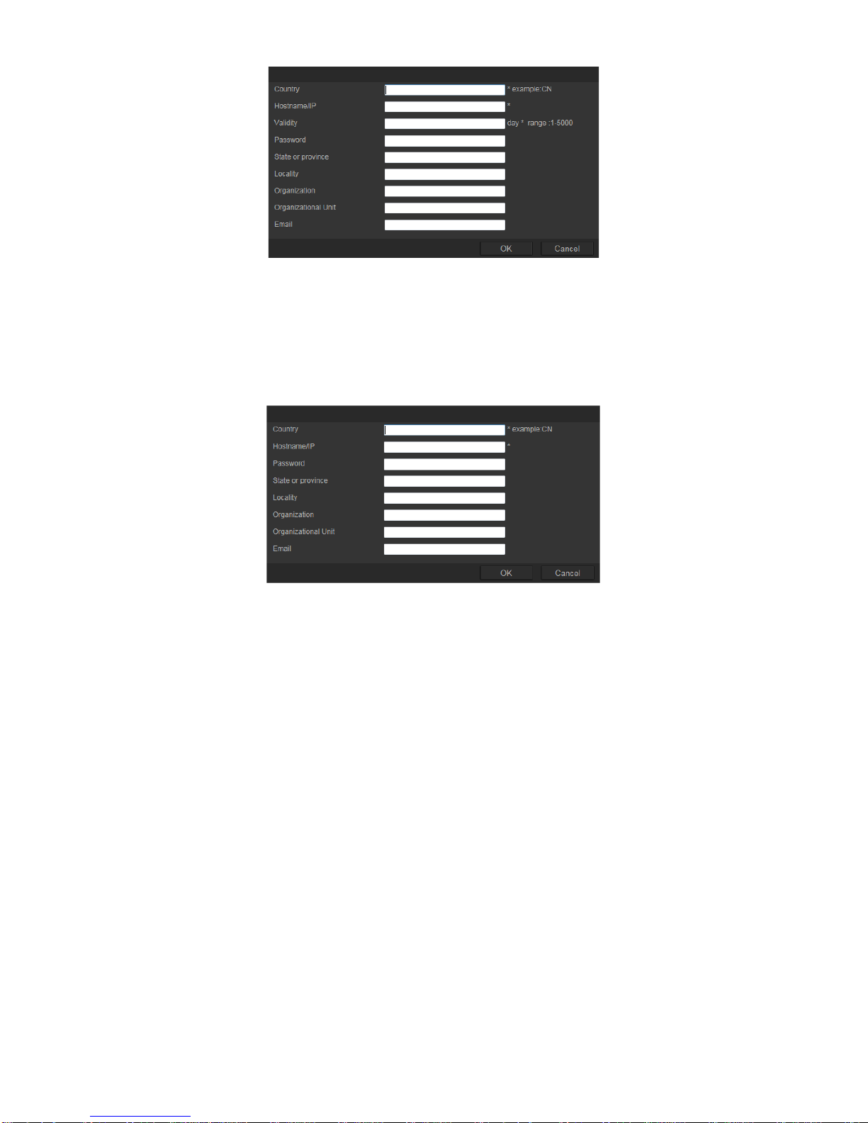
Click the Create button beside “Create Self-signed Certificate”. Enter the country,
host name/IP, validity and the other information requested.
Page 23
TruVision IP Thermal Camera Configuration Manual 21
Click OK to save the settings.
-Or-
Create a certificate request:
Click the Create button beside “Create Certificate Request”. Enter the country, host
name/IP, and the other information requested.
3. Click OK to save the settings. Download the certificate request and submit it to the
trusted certificate authority for signature, such as Symantec or RSA. After receiving
the signed valid certificate, upload the certificate to the device
Page 24
22 TruVision IP Thermal Camera Configuration Manual
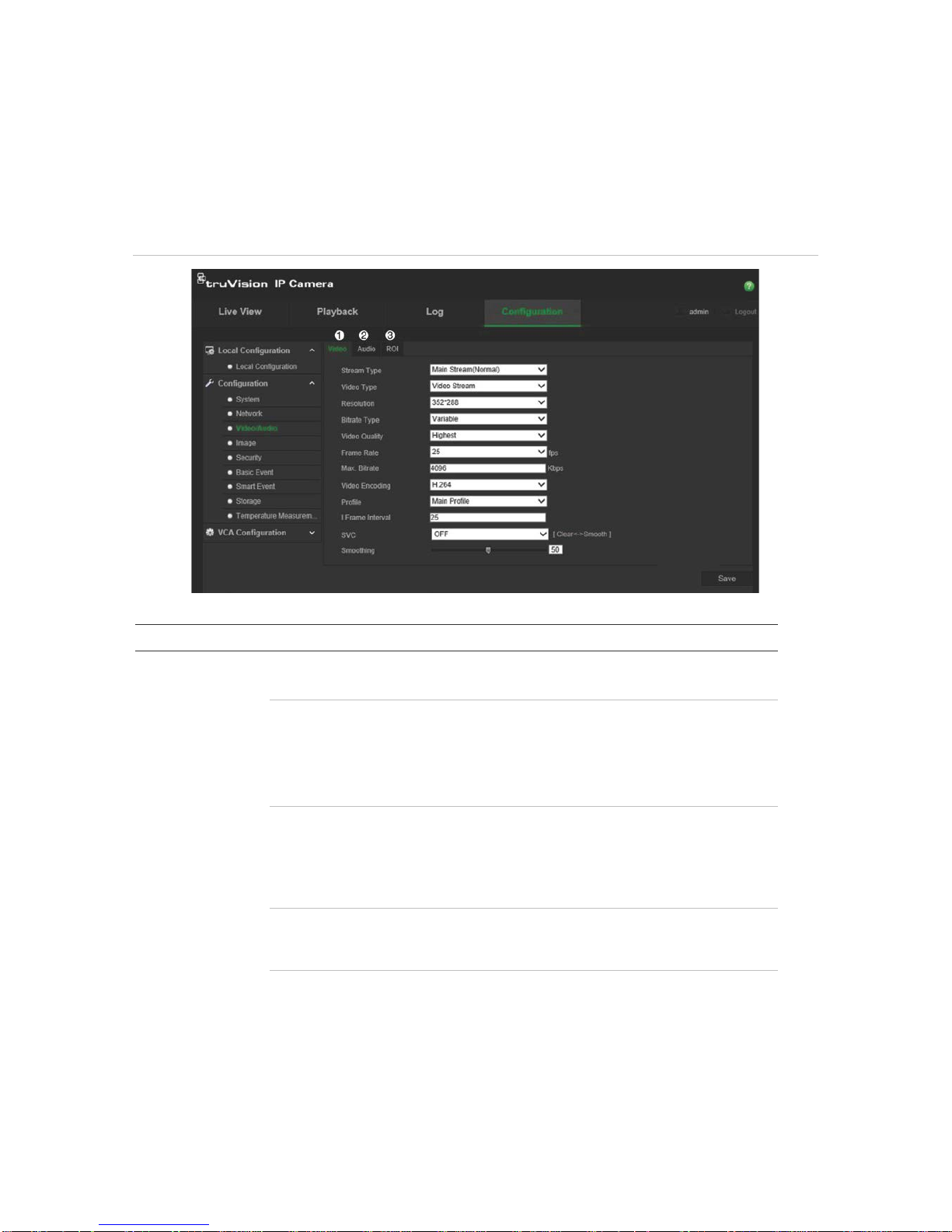
Video and audio configuration
You can adjust the video and audio recording parameters to obtain the picture quality
and file size best suited to your needs. Figure 5 below list the video and audio recording
options you can configure for the camera.
Figure 5: Video/Audio Settings menu (Video tab shown)
Tab Parameter descriptions
1.
Video
Stream Type: Specifies the streaming method used.
Options include: Main Stream (Normal), Substream, and Third stream.
Video Type: Specifies the stream type you wish to record.
Select Video Stream to record video stream only. Select Video&Audio to
record both video and audio streams.
Note: Video&Audio is only available for those camera models that support
audio.
Resolution: Specifies the recording resolution. A higher image resolution
provides a higher image quality but also requires a higher bit rate. The
resolution options listed depend on the type of camera and on whether main
or sub stream is being used.
Note: Resolutions can vary depending on the camera model.
Bitrate Type: Specifies whether variab le or fixed bit rate is used. Variable
produces higher quality results suitable for video downloads and streaming.
Default is Constant.
Video Quality: Specifies the quality level of the image. It can be set when
variable bit rate is selected. Options include: Lowest, Lower, Medium, Higher,
and Highest.
Page 25

TruVision IP Thermal Camera Configuration Manual 23
Tab Parameter descriptions
Frame Rate: Specifies the frame rate for the selected resolution.
The frame rate is the number of video frames that are shown or sent per
second.
Note: The maximum frame rate depends on the camera model and selected
resolution. Please select the camera specifications in its datasheet.
Max bit rate: Specifies the maximum allowed bit rate. A high image
resolution requires that a high bit rate must also be selected.
Video Encoding: Specifies the video encoder used.
Profile: Different profile indicates different tools and technologies used in
compression. Options include: High Profile, Main Profile, and Basic Profile.
I-Frame Interval: A video compression method. It is strongly recommended
not to change the default value 50.
SVC: The scalable video coding feature standardizes the encoding of a high-
quality video bit stream that contains one or more subset bit streams. Select
On, Off, or Auto.
Smoothing: Adjust the smoothness of the stream.
2.
Audio
Audio Encoding: G.722.1, G.711ulaw, G.711alaw, MP2L2, G.726, and PCM
are optional.
Audio Input: Only “Linein” is available for the pickup microphone.
Input Volume: Specifies the volume from 0 to 100.
Environmental Noise Filter:
Set it as OFF or ON. When you set the function
on the noise detected can be filtered.
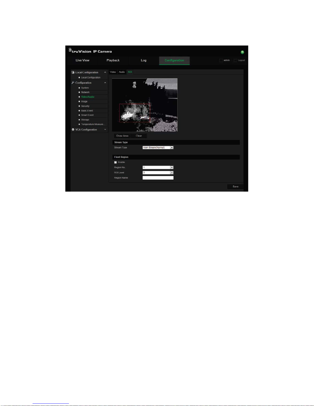
3.
ROI
This function lets you assign more encoding resources to the region of
interest (RoI) in order to increase the image quality of the RoI compared to
that of background. The RoI image then appears more focused than that of
the background. See page 24 for setup information
Page 26
24 TruVision IP Thermal Camera Configuration Manual
To configure RoI settings:
1. From the Configuration panel, click Configuration > Video/Audio > ROI.
2. Select the desired channel fro m the drop-down list.
3. Draw the region of interest on the image. Up to four regions can be drawn.
4. Choose the stream type to set the RoI encoding.
5. Enable Fixed Region to manually configure the area.
Region No.: Select the region.
ROI Level: Choose the image quality enhancing level.
Region Name: Set the desired region name.
6. Enable Dynamic Region for face detection.
ROI Level: Choose the image quality enhancing level.
7. Click Save to save changes.
Page 27
TruVision IP Thermal Camera Configuration Manual 25
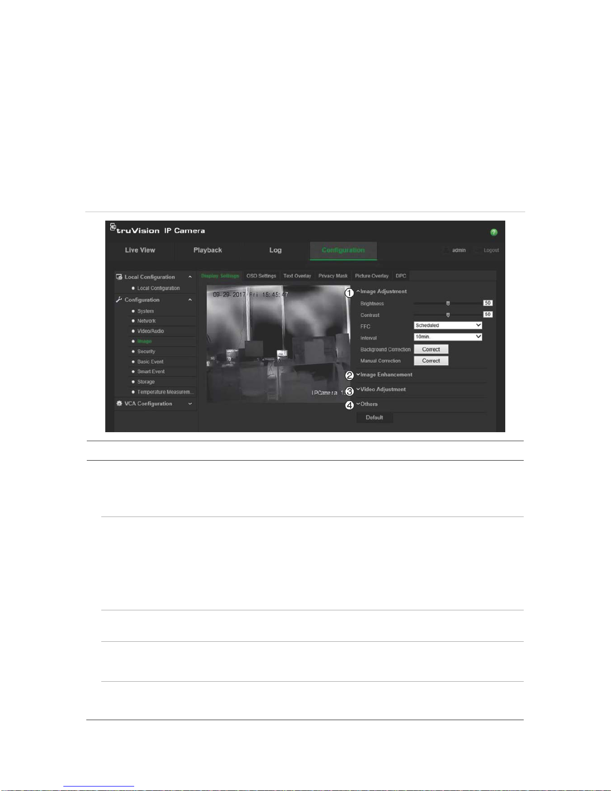
Image display configuration
You may need to adjust the camera image depending on the camera model or location
background to get the best image quality. You can adjust the brightness, contrast,
saturation, hue, and sharpness. See Figure 6 below.
Use this menu to also adjust camera behavior parameters such as exposure time, iris
mode, video standard, day/night mode, image flip, WDR, digital noise reduction, white
balance, and indoor/outdoor mode. All changes are automatically saved.
Figure 6: Image > Display Settings window
Parameter Description
1.
Image Adjustment
Brightness
,
Contrast
Modifies the different elements of the picture quality by adjusting the position of
the values for each of parameter.
F
FC (Flat Field
Correction)
This improves the quality of the digit a l image. It removes non-uniformities in the
image caused by different sensitivities of the pixels and by distortions caused by
optics. Select Scheduled, Temperature, or OFF.
Scheduled: Select the refresh interval to remove non-uniformities: 10, 20, 30, 40,
50, 60, 120, 180, or 240 minutes.
Temperature: Camera adjusts the live vi e w image according to its temperature.
OFF: Disable this function.
Interval
Specifies the interval time between checking live vie w images.
Select one of the options: 10, 20, 30, 40, 50, 60, 120, 180, or 240 minutes.
Background
Correction
Fully cover the lens with an object (a lens cover is recommended) and click the
“Correct” button. The camera then adjusts the image according to the current
environment.
Manual
Correction
Click the “Correct” button. The camera then adjusts the image according to the
temperature of the camera itself.
Page 28

26 TruVision IP Thermal Camera Configuration Manual
Parameter Description
2.
Image Enhancement
Digita
l Noise
Reduction
Digital noise reduction (DNR) reduces noise, especially in low light conditions, to
improve image performance.
Select Normal Mode, Expert Mode, or OFF. Default is Normal Mode.
Noise Reduction
Level
Only available when DNR is set to Normal Mode.
Set the level of noise reduction in
Normal Mode. The higher v alue, the stronger the noise reduction. Default is 50.
Palettes
Select the desired colors for the thermal view. Select White Hot, Black Hot, Fusion
1, Rainbow, Fusion 2, Ironbow 1, Ironbow 2, Sepia, Color 1, Color 2, Ice Fire
, Rain,
Red Hot, Green Hot, or Dark Blue. Default is White Hot.
DDE DDE (Digital Detail Enhancement) optimizes the image contrast. Select OFF or
Normal Mode.
DDE Level
When DDE is set to Norma l Mode, adjust the level between 1 and 100. Default is
50.
3.
Video Adjustment
Mirror
It mirrors the image so you can see it inversed. Select Center or OFF. Default is
OFF.
Video Standard
Select the video standard: 50 Hz or 60 Hz. 50 Hz for PAL standard and 60 Hz for
NTSC standard.
Capture Mode
Set the desired frame rate to meet the different demands of field of view and
resolution. A higher frame rate may be required in a location with a lot of
movement (such as a money depot).
Digital Zoom
Set t he dig ita l zoom ratio. Select 2x, 4x, or OFF. Default is OFF.
4.
Other
Local Output
Select ON or OFF to enable or disable the BNC output. Default is ON.
Note: Click the Default button to return all the image settings to default.
OSD
Use the onscreen display (OSD) function to display the camera name as well as the
system date and time on screen. You can also define how the text appears on screen.
Page 29

TruVision IP Thermal Camera Configuration Manual 27
To position the date/time and name on screen:
1. From the Configuration panel, click Configuration > Image > OSD Settings.
2. Select the Display Name box to display the camera’s name on screen.
3. Select the Display Date box to display the date/time on screen.
4. Select the Display Week box to include the day of the week in the on-screen
display.
5. In the Camera Name box, enter the camera name.
6. Select the time and date formats from the Time format and Date format list boxes.
7. Select a display mode for the camera from the Display Mode list box. Display
modes include:
• Tr ansparent & Not flashing. The image appears through the text.
• Tr ansparent & Flashing. The image appears through the text. The text flashes
on and off.
• Not transparent & Not flashing. The image is behind the text. This is default.
• Not transparent & Flashing. The image is behind the text. The text flashes on
and off.
8. Select the desired OSD size.
9. Select the desired font color: Black&White Self-adaptive or Custom. The Custom
option lets you select a specific color from the palette displayed (see the figur e
above). Default is Black&White Self-adaptive.
10. Use the mouse to click and drag the camera time/date and name frames in the live
view window to the desired positions.
11. Click Save to save changes.
Note: If you set the display mode as transparent, the text varies according the
background. With some backgrounds, the text may be not easily readable.
Page 30

28 TruVision IP Thermal Camera Configuration Manual
Overlay text
You can add up to four lines of text on screen. This option can be used, for example, to
display emergency contact details. Each text line can be positioned anywhere on
screen. See Figure 7 below.
Figure 7: Text overlay menu
To add on-screen text:
1. From the Configuration panel, click Configuration > Image > Text Ov erlay.
2. Select the box for the first li ne of tex t.
3. Enter the text in the text box.
4. Use the mouse to click and drag the red text frame in the live view window to the
desired position.
5. Repeat steps 2 to 4 for each extra line of text.
Note: Remove an overlay text on the OSD by deselecting its text line.
6. Click Save to save changes.
Page 31

TruVision IP Thermal Camera Configuration Manual 29
Privacy mask
Privacy masks let you conceal sensitive areas (such as neighboring windows) to protect
them from being viewed in live view and in recorded video. The masking appears as a
blank area on screen. You can create up to four privacy masks per camer a.
Note: There may be a small difference in size of the privacy mask area depending on
whether local output or the web browser is used.
To add privacy mask area:
1. From the Configuration panel, click Configuration > Image > Privacy Mask.
2. Select the Enable Privacy Mask box.
3. Click Draw Area.
4. Click and drag the mouse in the live video window to draw the area to mask.
Note: You can draw up to four areas on the s ame im ag e.
5. Click Stop Drawing to finish drawing, or click Clear All to clear all of the areas you
set without saving them.
6. Click Save to save changes.
Page 32

30 TruVision IP Thermal Camera Configuration Manual
Picture overlay
This function lets you overlay a picture on the image, such as a company logo for
example. The picture must be in RGB 24 bm p for mat an d th e max i mu m permitted size
is 128*128.
To add a picture:
1. From the Configuration panel, click Configuration > Image > Picture Overlay.
2. Under “Upload Picture”, click Browse to select a picture file and Upload to upload
it.
3. Select Enable Picture Overlay check box to enable the function.
Note: The X and Y coordinate values show the location of the picture on the image.
Picture width and height shows the size of the picture.
Defective pixel correction
A CCD or CMOS image sensor in a digital camera may have defective pixels, which
can fail to sense light levels correctly. The DPC (Defective Pixel Correction) function
allows the camera to correct defective pixels.
Note: This function is only available for certai n ca mera mo del s.
Page 33

TruVision IP Thermal Camera Configuration Manual 31
To set DPC:
1. From the Configuration panel, click Configuration > Image > DPC.
i
2. Click the desired area of the image to select the defective pixel. The cursor on the
image will move to the clicked position. If required, click ① to slightly adjust the
cursor position.
3. Click ② to start the correction.
4. If required, click ③ to cancel the correction.
Page 34

32 TruVision IP Thermal Camera Configuration Manual
Alarm configuration
You can configure the camera to identify many different types of alarm events, such as
motion detection, video tampering, alarm inputs and outputs, audio exception, intrusion
detection, and fire source detection.
Motion detection alarms
A motion detection alarm refers to an alarm triggered when the camera detects motion.
However, the motion alarm is only triggered if it occurs during a programmed time
schedule.
Select the level of sensitivity to motion as well as the target size so that only objects
that could be of interest can trigger a motion recording. For example, the motion
recording is triggered by the movement of a person but not that of a cat.
You can define the area on screen where the motion is detected, the level of sensitivity
to motion, the schedule when the camera is sensitive to detecting motion as well as
which methods are used to alert you to a motion detection alarm.
You can also enable dynamic analysis for motion. When there is motion, the area will
be highlighted as green frames.
Normal and expert configuration
There are two types of motion detection configuration. This allows you to set the motion
detection parameters depending on the motion detection environment and thereby help
to reduce false alarms.
Normal configuration mode allows you to set the sensitivity level of the motion
detection. It applies to both day and night mode.
Expert configuration mode gives you much more control over how motion is detected. It
lets you set the sensitivity level as well as to define the percentage of the motion
detection area that the object must occupy in the image, select day or night mode, and
set up eight differently config ur ed defined areas. See Figure 8, item 1.
Page 35

TruVision IP Thermal Camera Configuration Manual 33
Figure 8: Motion detection window with a motion sen sitive grid shown
Defining a motion detection alarm requires the following tasks to be done:
Area settings: Define the on-screen area that can trigger a motion detection alarm
and the detection sensitivity level (see Figure 8, item 1).
Arming schedule: Define the schedule during which the system detects motion
(see Figure 8, item 2).
Recording schedule: Define the schedule during which motion detection can be
recorded. See “Recording schedule” on page 67 for further information.
Linkage: Specify the method of response to the alarm (see Figure 8, item 3).
Page 36

34 TruVision IP Thermal Camera Configuration Manual
To set up motion detection in normal mode:
1. From the Configuration panel, click Configuration > Basic Event > Motion
Detection.
2. Set the motion detection area .
a) Select the Enable Motion Detection box. Select Enable Dynamic Analysis for
Motion if you want to see real-time motion events.
Note: Select Disable under Rules in the Local Configuration menu if you do not
want the detected object displayed in green frames.
b) Select Normal mode from the drop-down menu.
c) Click Draw Area. Click and drag the mouse on the live video image to draw an
area sensitive to motion detection.
d) Click Stop Drawing to finish drawing. Click Clear All to delete all areas marked
and restart drawing .
e) Move the Sensitivity slider to set the sensitivity of the detection. All areas will
have the same sensitivity level.
3. Set the arming schedule.
a) Click Edit to edit the arming schedule. The “Edit Schedule Time” pop-up window
appears.
b) Select the day of the week and click to set the detailed time period. You can
copy the schedule to other days of the week by selecting the check boxes for the
desired days of the week and clicking Copy.
c) Click OK to save changes and to return to the motion detection window.
4. Specify the linkage method for when an event occurs.
Select one or more response methods for the system when a motion detection
alarm is triggered.
Page 37

TruVision IP Thermal Camera Configuration Manual 35
Notify
Surveillance Center Send an exception or alarm signal to remote management software
when an event occurs.
Send
Email Sends an email to a specified address when there is a motion
detection alarm.
Note: You must configure email settings before enabling this option.
See “To set up the email parameters” on page 18 for further
information. If you want to send the event snapshot together with the
email, select the Attached Snapshot option.
Upload
to FTP Captures the image when an alarm is triggered and uploads the
snapshot to an FTP server.
Note: To upload the snapshot to an FTP, you must first configure the
FTP settings. See “To define the FTP parameters” on page 18 for
further information. Enable the Upload Type option.
To upload the snapshot to FTP when motion detection or an alarm
input is triggered, you must also select the Enable Event-triggered
Snapshot check box in the snapshot parameters. See “Snapshot
parameters” on page 54 for further information.
Trigger Channel
Triggers the recording to start in the camera.
Trigger Alarm Output
Trigger external alarm outputs when an event occurs. Select “Select
All” or individual alarm outputs.
Note: This option is only supported by cameras that support alarm
output.
5. Click Save to save changes.
To set up motion detection in expert mode:
1. From the Configuration panel, click Configuration > Basic Event > Motion
Detection.
2. Set the motion detection area .
a) Select the Enable Motion Detection box. Select Enable Dynamic Analysis for
Motion if you want to see real-time motion events.
Note: Select Disable under Rules in the “Local Configuration” menu if you do
not want the detected object displayed in green frames.
b) Select Expert mode fr om the dr op-down menu.
Page 38

36 TruVision IP Thermal Camera Configuration Manual
c) Under Switch Day and Night Settings, select OFF, Auto-switch, or Scheduled-
switch. Default is OFF.
OFF No day/night switching.
Auto-switch Defines the different settings for day and night.
Scheduled switch Defines the different settings for day and night as well as when
day/night starts and ends.
d) Under Area, select the desired area number and then click Dra w Area. Click
and drag the mouse on the live video image to draw an area sensitive to motion
detection.
Note: You can draw up to eight motion detection areas on the same live view
image.
e) Set the sensitivity of the selected area to motion detection.
Move the Sensitivity slider to set the sensitivity of the detection for the selected
area.
f) Set the proportion of the object that must be in the selected area to trigger an
alarm.
If OFF selected: Move the Proportion of Object on Area slider to set the
proportion of the object that must occupy the defined area to trigger an alarm.
– Or –
If Auto-Switch: Move the Proportion of Object on Area slider to set the
proportion of the object that must occupy the defined area to trigger an alarm.
– Or –
If Scheduled Switch selected: Move the Proportion of Object on Area slider to
set the proportion of the object that must occupy the defined area t o trigger an
alarm. Also set when the day starts and ends.
g) Click Stop Drawing to finish drawing. Click Clear All to dele te al l areas mark ed
and restart drawing .
h) Click Save to save the changes for that area.
i) Repeat steps (d) to (h) for each area to be defined.
3. Set the arming schedule.
a) Click Edit to edit the arming schedule. The “Edit Schedul e Tim e” window
appears.
Page 39

TruVision IP Thermal Camera Configuration Manual 37
b) Select the day and click to set the detailed ti me peri od .
c) Click OK to save changes.
4. Specify the linkage method for when an event occurs.
Select one or more response methods for the system when a motion detection
alarm is triggered.
Notify
Surveillance Center Send an exception or alarm signal to remote management software
when an event occurs.
Send Email
Sends an email to a specified address when there is a motion
detection alarm.
Note: You must configure email settings before enabling this option.
See “To set up the email parameters” on page 18 for further
information. If you want to send the event snapshot together with the
email, select the “Attached Snapshot” option.
Upload
to FTP Captures the image when an alarm is triggered and uploads the
snapshot to an FTP server.
Note: To upload the snapshot to an FTP, you must first configure the
FTP settings. See “To define the FTP parameters” on page 18 for
further information. Enable the Upload Type option.
To upload the snapshot to FTP when motion detection or an alarm
input is triggered, you must also select the Enable Event-triggered
Snapshot check box in the snapshot parameters. See “Snapshot
parameters” on page 54 for further information.
Trigger Channel
Triggers the recording to start in the camera.
5. If required, select another day of the week to set a different schedule, or copy the
same schedule to other days of the week.
6. Click Save to save changes.
Page 40

38 TruVision IP Thermal Camera Configuration Manual
Video tampering alarms
You can configure the camera to trigger an alarm when the lens is covered and to take
an alarm response action.
Figure 9: Tamper-proof alarm window
To set up video tampering alarms:
1. From the Configuration panel, click Configuration > Basic Event > Video
Tampering.
2. Select the Enable Video Tampering check box.
3. Move the Sensitivity slider to set the detection sensitivity. The sensitivity applies to
the whole screen.
4. Click Edit to edit the arming schedule. The arming schedule configuration is the
same as that for motion detection. See “Set the arming schedule” on page 36 for
more information.
5. Specify the linkage method when an event occurs. Select one or more response
methods for the system when a tamper-proof alarm is triggered.
Notify
Surveillance Center Send an exception or alarm signal to remote management software
when an event occurs.
Page 41

TruVision IP Thermal Camera Configuration Manual 39
Send Email
Sends an email to a specified address when there is an alarm
triggered.
Note: You must configure email settings before enabling this option.
See “To set up the email parameters” on page 18 for further
information. If you want to send the event snapshot together with the
email, select the Att ac hed Snaps hot opt ion .
Trigger Alar
m Output Trigger external alarm outputs when an event occurs. Select “Select
All” or individual alarm outputs.
Note: This option is only supported by cameras that support alarm
output.
6. Click Save to save changes.
Alarm inputs and outputs
To define the external alarm input:
1. From the Configuration panel, click Configuration > Basic Event > Alarm Input.
2. Choose the Alarm Input No. and the Alarm Type. The alarm type can be NO
(Normally Open) or NC (Normally Closed). Enter a name for the alarm input, if
desired.
3. Click Edit to set the arming schedule for the alarm input. The arming schedule
configuration is th e sa me as that for motion detection. See “Set the arming
schedule” on page 36 for more information.
4. Specify the linkage method. Select one or more response methods for the system
when an alarm input is triggered.
Notify
Surveillance Center Send an exception or alarm signal to remote management software
when an event occurs.
Send Email
Sends an email to a specified address when there is an alarm input
or output alarm.
Note: You must configure email settings before enabling this option.
See “To set up the email parameters” on page 18 for further
information. If you want to send the event snapshot together with the
email, select the Attached Snapshot option.
Trigger Alarm Output
Trigger external alarm outputs when an event occurs. Select “Select
All” or individual alarm outputs.
Note: This option is only supported by cameras that support alarm
output.
5. Click Save to save changes.
To define alarm output:
1. From the Configuration panel, click Configuration > Basic Event > Alarm Output.
2. Select one alarm output channel from the Alarm Output drop-down list. You can
also set a name for the alarm output.
3. The delay time can be set to 5 s, 10 s, 30 s, 1 min, 2 min, 5 min, or 10 min. The
delay time refers to the time duration that the alarm output remains in effect after the
alarm occurs.
Page 42

40 TruVision IP Thermal Camera Configuration Manual
4. Click Edit to set the arming schedule. The arming schedule configuration is the
same as that for motion detection. See “Set the arming schedule” on page 36 for
more information.
5. If required, select another day of the week to set a different schedule for alarm
outputs, or copy the same schedule to other days of the week.
6. Click Save to save changes.
Exception alarms
You can set up the camera to notify you when unexpected events occur and how you
should be notified. These exception alarms include:
• HDD Full: All recording space on the NAS is full.
• HDD Error: Errors occurred while files were being written to the storage, no storage
or storage had failed to init ial i ze.
• Network Disconnected: Disconnected network cable.
• IP Address Conflicted: Conflict in IP address setting.
• Illegal Login: Wrong user ID or password used to login to the cameras.
To define exception alarms:
1. From the Configuration panel, click Configuration > Basic Event > Exception.
2. Under Exception Type, select an exception type from the drop-down list.
3. Specify the linkage method for when an event occurs. Select one or more res ponse
methods for the system when an exception alarm is triggered.
Notify Surveillance Center
Send an exception or alarm signal to remote management software
when an event occurs.
Send Email
Sends an email to a specified address when there is an exception
alarm.
Note: You must configure email settings before enabling this option.
See “To set up the email parameters” on page 18 for further
information. If you want to send the event snapshot together with the
email, select the Att ac hed Snaps hot opt ion .
Trigger Alarm Output
Trigger external alarm outputs when an event occurs. Check “Select
All” or individual alarm outputs.
Note: This option is only supported by cameras that support alarm
output.
4. Click Save to save changes.
Page 43

TruVision IP Thermal Camera Configuration Manual 41
Audio exception detection
The “Audio Exception Detection” function detects sounds that are above a selected
threshold.
Figure 10: Audio exception detection window
To define audio exception detection:
1. From the Configuration panel, click Configuration > Smart Event > Audio
Exception Detection.
2. Select Audio Loss Exception to activate the function.
3. Select Sudden Increase of Sound Intensity Detection to detect if there is a sudden
increase in sound in the surveillance scene. Also set the detection sensiti v i ty and
threshold for sudden increases in sound.
Sensitivity: The smaller the value, the larger the change required to trigger
detection. The range is between 1 and 100.
Sound Intensity Threshold: This option filters the sound in the environment. The
louder the environment al sound, the higher the value. Adjust it according to the
actual environment. The range is between 1 and 100.
4. Select the check box of Sudden Decrease of Sound Intensity Detection to detect the
sound sudden drop in sound in the surveillance scene. You can set the detection
sensitivity and threshold for sudden decreases in sound.
Sensitivity: The smaller the value, the larger the change should be to trigger the
detection. The range is between 1 and 100 .
Sound Intensity Threshold: This option filters the sound in the environment. The
louder the environment al sound, the higher the value. Adjust it according to the
actual environment. The range is between 1 and 100.
5. Click Edit to set the arming schedule. The arming schedule configuration is the
same as that for motion detection. See “Set the arming schedule” on page 36 for
more information.
Page 44

42 TruVision IP Thermal Camera Configuration Manual
6. Specify the linkage method. Select one or more response methods for the system
when an audio exception alarm is triggered.
Notify
Surveillance Center Send an exception or alarm signal to remote management
software when an event occurs .
Send Email
Sends an email to a specified address when there is a motion
detection alarm.
Note: You must configure email settings before enabling this
option. See “To set up the email parameters” on page 18 for
further information. If you want to send the event snapshot
together with the email, select the Att ached Sn aps ho t opti on.
Trigger Channel
Triggers the recording to start in the camera.
Trigger Alarm Output
Trigger external alarm outputs when an event occurs. Select
“Select All” or individual alarm outputs.
Note: This option is only supported by cameras that support
alarm output.
7. Click Save to save changes.
Scene change detection
You can configure the camera to trigger an alarm when the c am er a detects a change in
the scene caused by an intentional rotation of the camera.
Figure 11: Scene change detection window
Page 45

TruVision IP Thermal Camera Configuration Manual 43
To define scene change detection:
1. From the Configuration panel, click Configuration > Smart Event > Sc ene Change
Detection.
2. Select the Enable Scene Change Detection check box to enable the function.
3. Configure the sensitivity ranging from 1 to 100. The higher the sensitivity, the easier
the change of scene can trigger an alarm.
3. Click Edit to set the arming schedule for the alarm input. See “Set the arming
schedule” on page 36 for more information.
4. Specify the linkage for method when an event occurs. Select one or more response
methods for the system when a scene change detection alarm is triggered.
Notify
Surveillance Center Sends an exception or alarm signal to remote management software
when an event occurs.
Send Email
Sends an email to a specified address when there is a scene change
detection alarm.
Note: You must configure email settings before enabling this option.
See “To set up the email parameters” on page 17 for further
information. If you want to send the event snapshot together with the
email, select the Attached Snapshot option
Upload
to FTP Captures the image when an alarm is triggered and uploads the
snapshot to an FTP server.
Note: To upload the snapshot to an FTP, you must first configure the
FTP settings. See “To define the FTP parameters” on page 18 for
further information. Enable the Upload Type option.
To upload the snapshot to FTP when motion detection or an alarm
input is triggered, you must also select the Enable Event-triggered
Snapshot check box in the snapshot parameters. See “Snapshot
parameters” on page 54 for further information.
Trigger Channel
Triggers the recording to start in the camera.
Trigger Alarm
Output Triggers external alarm outputs when an event occurs. Select Select
All or individual alarm outputs.
Note: This option is only supported by cameras that support alarm
output.
5. Click Save to save changes.
Fire source detection
You can configure the camera to trigger an alarm when the c am er a detects a fire
source.
IMPORTANT NOTICE: This fire detection feature is not a substitute for a
certified fire detection s ystem.
Page 46

44 TruVision IP Thermal Camera Configuration Manual
Note: This function is only available when Fire Source Detection has been enabled
under the menu Configuration > System > VCA Resource Type. See “VCA resource
type” on page 54 for more information.
To define the fire source detection:
1. From the Configuration panel, click Configuration > Smart Event > Fire Source
Detection.
2. Select the Enable Fire Source Detection check box to enable the f unct ion. When a
fire source is detected, a red frame appears around the source in the live view
image.
Note: When Enable Fire Source Detection is enabled, an extra function appears
under the Local Configuration window that allows you to enable how the fire
information is displayed on the camera. See the instructi ons on page 18 for further
information.
3. Slide the sensitivity cursor to adjust the sensitivity level of the fire source detection
from 1 to 100. The larger the number, the higher the detection sensitivity level.
Default is 50.
4. Set the arming schedule.
a) Click Edit to edit the arming schedule. The “Edit Schedule Time” window
appears.
Page 47

TruVision IP Thermal Camera Configuration Manual 45
b) Select the desired day and click to set the detailed time period. You c an copy
the schedule to other d ays. Default is one period of 24 hours per day.
c) Click OK to save changes.
5. Specify the linkage method when an event occurs. Select one or more response
methods for the system when a fire source detection alarm is triggered.
No
tify Surveillance Center Sends an exception or alarm signal to remote management
software when an event occurs .
Send Email
Sends an email to a specified address when there is a scene
change detection alarm.
Note: You must configure email settings before
enabling this option.
See “To set up the email parameters” on page 17 for further
information. If you want to send the event snapshot together with
the email, select the “Attached Snapshot” option
Upload to FTP
Captures the image when an alarm is triggered and uploads the
snapshot to an FTP server.
Note: To upload the snapshot to an FTP, you must first configure
the FTP settings. See “To define the FTP parameters” on page 18
for further information. Enable the Upload Type option.
To upload the snapshot to FTP when motion detection or an alarm
input is triggered, you must also select the Enable Event-
triggered
Snapshot check box in the snapshot parameters. See “Snapshot
parameters” on page 54 for further information.
Trigger Channel
Triggers the recording to start in the camera.
Trigger Alarm Output
Triggers external alarm outputs when an event occurs. Select
“Select All” or individual alarm outputs.
Note: This option is only supported by cameras that support alarm
output.
6. Click Save to save changes.
To display fire source information in live view:
1. From the Configuration panel, click Local Configuration.
2. Under Fire Point, select one or more options on how to display the fire information.
Page 48

46 TruVision IP Thermal Camera Configuration Manual
Display Highest
Temperature Displa y the highest temperature.
Locate Highest Temperature
Point
Specify where the fire is located.
Frame Fire
Point Display a red frame around the fire source during video streaming
when a fire is detected.
The option is disabled by default.
3. Click Save to save changes.
Temperature measurement
The camera can measure the actual temperature of a point/line/frame being monitored.
The camera triggers an alarm when the temperature exceeds the defined temperature
threshold value.
Notes:
This function is only available when Temperature Measurement + Behavior
Analysis + Standard VCA Functions has been enabled under the menu
Configuration > System > VCA Resource Type. See “VCA resource type” on
page 54 for more informati o n.
When Temperature Measurement + Behavior Analysis + Standard VCA
Functions is enabled, an extra function appears in the “Local Configuration”
window that allows you to select if the fire information is displayed on the live view
image.
To set the temperature measurement:
1. From the Configuration panel, click Configuration > Temperature Measurement >
Temperature Measurement Configuration.
Page 49

TruVision IP Thermal Camera Configuration Manual 47
2. Select the check boxes of the interface to set the temperature measurement
configurations.
Enable Temperature M easur em en t : Select the check box to enable
temperature measure men t func ti o n.
Display Temperature Info. on Stream: Select the check box to display
temperature information in live view.
Add Original Data on Capture: Select the check box to add original data on
capture.
Add Original Data on Stream: Select the check box to add original data on
stream.
Data Refresh Interval: Select the data refresh interval from 1s to 5s.
Unit: Display temperature in Degree Celsius, Degree Fahrenheit, or Degree
Kelvin.
Temperature Range: Select the temperature range: -20 to 150 °C, -4 to 302 °F,
or 253 to 423 K.
Emissivity: Set the emissivity (ability to emit infrared energy) of your target.
Values range from 0 (completely reflective target) to 1 (object emitting no
infrared energy) .
Note: The emissivity of each object is different.
Distance: Manually enter the straight-line distance between the target and the
device.
3. Click Save to save the settings.
4. From the Local Configuration panel, click Local Configuration and enable Display
Temperature Info. on Camera. The option is disabled by default.
Page 50

48 TruVision IP Thermal Camera Configuration Manual
Click Save to save the setting.
Note: This option is not available if Temperature Measurement + Behavior
Analysis + Standard VCA Functions is disabled in the Configuration > System >
VCA Resource Type menu.
To set the temperature measurement and alarm:
Use this function to measure the temperature of the selected point/line/frame. The
device compares temperature of selected regions and alarms.
1. From the Configuration panel, click Configuration > Temperature Measurement >
Temperature Measurement and Alarm.
2. Draw the desired point, line or frame where you want to monitor a loc ati on on the
live view image. Each point, line, and frame must be created individually and the
rules associated with it configured before you can create the next point/line/frame.
Click the Point icon and then click the spot on the image where you want to monitor a
specific point.
Page 51

TruVision IP Thermal Camera Configuration Manual 49
Click the Line icon and then left- click where you want the line to start and end on the
image. Right-click to finish drawing the area.
Click the Frame icon and then left- click where you want the line to start and end on the
image. Right-click to finish drawing the area.
Delete all points, lines, and frames on the image.
Note: You can draw up to a total of 10 points, 1 line, and 10 frames.
3. Set the temperature measurement rules for the point/line/frame just created.
Select the check box of the first rule and enter the following information about this
rule. You can set up to up to 21 rules (10 points, 1 line, and 10 frames).
Name: Enter the desired name for the rule.
Type: Select Point, Line, or Frame as the rule type.
Point: This is the temperature of the point you inserted in the live view image.
Line: This is the temperature of the line you drew in the live view image.
Frame: This is the temperature of the area you drew in the live view image.
Emissivity: Set the emissivity (ability to emit infrared energy) of your target.
Values range from 0 (completely reflective target) to 1 (object emitting no
infrared energy) .
Distance (m): Enter the straight-line distance between the target and the
device.
Reflective Temperature: If there are any targets with high emissivity in the
scene, select the check box and set the reflective temperature to correct the
temperature. Default is unchecked.
Page 52

50 TruVision IP Thermal Camera Configuration Manual
4. Set the alarm rules for the point/line/frame just created.
Point rule:
a) Click to display the “Alarm Rule” setup window.
b) From the drop-down list, select one of the “Alarm Rule” options: Average
Temperature is Higher than, or Average Temperature is Lower than.
For example, select “Alarm Rule” as Average Temperature is Higher than, and
set the “Alarm Temperature” to 50 °C (122 F°). The device triggers a n alarm
when its average temperature is higher than 50 °C.
c) Enter the temperature values of the Alarm Pre-Alarm Temperature, Alarm
Temperature, and Tolerance Temperature.
For “Tolerance Temperature”, the triggered alarm stops when the device
temperature/temperature difference is less than the rule temperature by the set
tolerance temperature. For example, set the tolerance temperature to 3 °C
(37.4 °F), set alarm temperature to 55 °C (131 °F), and set pre-alarm
temperature to 50 °C (122 F°). The device sends a pre-alarm when its
temperature reaches 5 0 °C (122 °F) and it triggers an alarm when its
temperature reaches 5 5 °C (131 °F). Only when the device temperature is lower
than 52 °C will the alarm be cancelled.
d) Click OK to save the changes.
Line rule:
a) Click to show the Alarm Rule setup window.
b) Set the alarm rule. Select one of the six options:
Max. temperature is higher than, Max. temperature is lower than, Min.
temperature is higher than, Min. temperature is lower than, Average temperature
is higher than, or Average temperature is lower than.
c) Enter the values of the Alarm Pre-Alarm Temperature, Alarm Temperature, and
Tolerance Temperature.
Page 53

TruVision IP Thermal Camera Configuration Manual 51
For example, for “Alarm Rule” select Min. Temperature is Lower than, and set
the “Alarm Temperatur e” to 40 °C (104 F°). The device triggers an alarm when
the minimum temperature is lower than 40 °C.
d) Click OK to save the changes.
Frame rule:
Single frame
a) Click to show the Alarm Rule setup window.
b) Set the alarm rule. Select one of the options from the dr op-down list:
Max. temperature is higher than, Max. temperature is lower than, Min.
temperature is higher than, Min. temperature is lower than, Average temperature
is higher than, Average temperature is lower than, Temperature difference is
higher than, or Temperature difference is lower than.
c) Enter the temperature values of the Alarm Pre-Alarm Temperature, Alarm
Temperature, and Tolerance Temperature.
For example, select “Alarm Rule” as Temperature Difference is Higher than,
and set the “Alarm Temperature” to 10 °C (50 F°). The device triggers an alarm
when the difference between the minimum temperature and the maximum
temperature of the region is higher than 10 °C.
d) Click OK to save the changes.
- Or -
Two or more frames
When using two or more alarm frames, set the alarm for the region temperature
difference between two frames.
a) In the Temperature Measurement and Ala rm widow, enable the frames alarm
rules that you want to include in the region temperature difference.
b) Click the Region Temperature Difference Alarm button to display the “Region
Temperature Difference Alarm” window.
Page 54

52 TruVision IP Thermal Camera Configuration Manual
c) Select the Rule 1 check box and select two frame rules from the drop-down lists
to compare the saved regions.
d) Set the alarm rules and the temperature.
For example, for Rule 1 select Temperature Difference is Higher than, and
enter 10 °C (50 F°). An alarm is triggered when the difference between the
minimum and the maximum region temperatures is greater than 10 °C.
Note: The Region Temperature Difference Alarm only applies to the targets
set by the frames.
e) To compare other pairs of frame rules, click the next rule check box and repeat
the instructions described in steps c and d.
f) Click OK to save the changes.
5. Set the alarm linkage.
Click the Alarm Linkage button to enter the alarm linkage window and select the
desired linkage methods. The linkage methods selected apply to all regi on
temperature difference alarms.
Notify
Surveillance
Center
Send an exception or alarm signal to remote management software
when an event occurs.
Send Email
Send an email to a specified address when there is an alarm input or
output alarm.
Note: You must configure email settings before enabling this option.
See “To set up the email parameters” on page 18 for further
information. If you want to send the event snapshot together with the
email, select the Attached Snapshot option.
Page 55

TruVision IP Thermal Camera Configuration Manual 53
Upload
to FTP Capture the image when an alarm is triggered and upload the
snapshot to an FTP server.
Note: To upload the snapshot to an FTP, you must first configure the
FTP settings. See “To define the FTP parameters” on page 18 for
further information. Enable the Upload Type option.
To upload the snapshot to an FTP when motion detection or an alarm
input is triggered, you must also select the Enable Event-triggered
Snapshot check box in the snapshot parameters. See “Snapshot
parameters” on page 45 for further information.
Trigger Channel
Triggers the recording to start in the camera.
Trigger Ala
rm Output Trigger external alarm outputs when an event occurs. Select Select
All or each individual alarm output.
Note: This option is only supported by cameras that support an
alarm
output.
Click OK to save the changes.
6. If required, create another new point, line, or frame and set up the rules associated
with it. Repeat steps 2 to 5.
7. Click Save to save the settings.
Page 56

54 TruVision IP Thermal Camera Configuration Manual
VCA configuration
The camera can do video content analysis (VCA) and send the video analytics results
(metadata) to an NVR or other platforms to generate a VCA alarm.
VCA resource type
You need to specify which type of VCA resource is to be used.
To select the VCA resource type:
1. From the Configuration panel, click Configuration > System > VCA Resource
Type.
2. Select one of the options:
Measurement + Behavior Analysis + Standard VCA Functions: When enabled,
this lets you configure the parameters to measure temperature, display VCA
information and behavioral analysis. See “VCA information” below and “Behavior
analysis” on page 56 for more information.
Fire Source Detection: When enabled, this lets you configure the parameters to
configure the parameters to trigger an alarm when the camera detects a fire source.
See “Fire source detection” on page 43 for further information.
3. Click Save to save the settings.
VCA information
You can set up the camera to display information on the target and alarm rules in the
video image. You can also configure the quality and resolution of snapshots and
streamed images. This function also displays the version of the algorithm library used.
Note: This function is only available when Temperature Measurement + Behavior
Analysis + Standard VCA Functions has been enabled under the menu
Configuration > System > VCA Resource Type. See the section “VCA res ourc e type”
above.
To set up VCA information:
1. From the Configuration panel, click VCA Configuration > V CA Info
2. Select the check boxes for the desired display information and snapshot settings.
Page 57

TruVision IP Thermal Camera Configuration Manual 55
Behavior Analysis Version
Displays the version of the algorithms library.
Display I
nformation Displays the target infor mation on the alarm snapshot and video
stream. Select the check boxes to enable the desired display
method.
Display Target info. on Alarm Snapshot: When enabled, a frame
of the target information is displayed on the uploaded alarm
snapshot.
Display Rule info. on Alarm Snapshot:
When enabled, a frame of
the information about the captured target and the configured area
is displayed on the uploaded alarm snapshot.
Display VCA info. on Stream: A green frame is displayed on the
target when in live view or playback.
Note: “Rules” must be enabled in your local settings. Go to
Configuration > Local Configuration > R u les to enable the
option.
Snapshot Settings
Set the quality and resolution for the captured snapshot.
Upload JPEG Image to Center: Select the check box
to upload the
captured image to the surveillance center when a VCA alarm
occurs.
Snapshot Quality: Select High, Medium, or Low from the dropdown list.
3. Click Save to save the settings.
Page 58

56 TruVision IP Thermal Camera Configuration Manual
Behavior analysis
The camera can analyze video data from real-time behavior and smart filters to help
detect unwanted event s. When an alarm is triggered, pre-defined linkage methods are
then activated.
Note: This function is only available when Temperature Measurement + Behavior
Analysis + Standard VCA Functions has been enabled under the menu
Configuration > System > VCA Resource Type.
To set up behavior analysis:
1. From the VCA Configuration panel, click VCA Configuration > VCA Info and
enable the display information and snapshot settings (see “VCA information” on
page 54).
2. Set the camera calibration values to calculate the size of every target in the live view
image. The VCA detection will be more accurate if you configure the camera
calibration.
a) From the Configuration panel, click VCA Configuration > Camera Calibration.
b) Select the Camera Calibration check box to enabl e this function.
Note: The measurements made by the camera are only approximations and are
not 100% accurate.
Draw on Live
View Video:
Click Horizontal Line or Vertical Line to draw a horizontal/vertical line on
the live view image. Using the mouse, adjust the length of the line, if
required. Enter the actual length in meters of each drawn line in the Real
Length field. Lines can be up to 100 m long.
You must draw at least four verification lines and enter their lengths. Each
line is automatically numbered so it is easy to identify which specified length
applies to which line by clicking on a line.
Using these drawn reference lines and their actual lengths, the camera can
then measure the length of other objects that appear in live view.
Click Delete to delete all drawn lines.
Page 59

TruVision IP Thermal Camera Configuration Manual 57
c) Select the Enable Verification of Camera Calibration check box. Click the
Horizontal Verify/Vertical Verify button to draw a horizontal/vertical line in live
view. Then click the Calibrate button to calculate the line length. Compare the
calculated line length to the actual length to verify the calibration information you
set. If they do not match, you need to recalibrate the camera by drawing new
lines. This step is optional.
d) Click Save to save the settings.
Note: If live view stops, you cannot calibrate the camera.
3. Draw the shield region.
The shield region is a specified region in the live view image where behavior
analysis will not be carried out. You can set up to four shield regions.
a) From the Configuration panel, click VCA Configuration > VCA Configuration
> Shield Region.
b) Click Draw Area. In the live view window, draw the desired area by left-clicking
the end-points. Right-click the mouse to finish drawing the area.
Notes:
You can draw a polygon area with up to 10 sides.
Click Delete to delete all drawn areas.
If live view stops, you cannot draw a shield region.
c) Click Save to save the settings.
4. Set the rules.
You can set rules to identify different behavioral types, including cross line detection,
intrusion detection, region entry detection, and region exit detection, as well as to
filter objects that fit within a defined size.
Note: The rule types available depend on the camera model.
a) From the Configuration panel, click Configuration > VCA Configuration > Rule.
b) Click to add a new rule. Click to delete a rule.
c) Select the check box of the desired rule to enable behavior analysis.
d) Enter the name of the rule.
e) Select the rule type. The rule types are:
None. The rule is ignored.
Cross Line detects people, vehicles, or other objects that cross a pre-
defined virtual line. When enabled, you must select the crossing direction
before drawing a line. Select bidirectional, A-to-B, or B-to-A.
Intrusion detects people, vehicles, or other objects that enter and loiter in a
pre-defined virtual area. When enabled, you must set the dur a ti on ti me for
intrusion. The duration range is from 1 to 100 s.
Page 60

58 TruVision IP Thermal Camera Configuration Manual
Region Entrance detects people, vehicles, or other objects that enter a pre-
defined virtual area.
Region Exit detects people, vehicles, or other objects that exit a pre-defined
virtual area.
f) Select the filter type. You can set the system to detect an object that is within a
defined size range.
Under “Filter by”, select Actual Size or Pixel.
Actual Size: Enter the length and width in meter s of both the max i m um and
minimum sizes. Only a target whose size is between the minimum and maximum
values will trigger an alarm. If you select the actual size option, you must
configure the camera calibration.
Pixel: Click the Min. Size button and draw a minimum size rectangle on the live
view image. Click the Max. Size button and draw a maximum size rectangle on
the live view image. A target that is smaller than the minimum size or larger than
the maximum size will be filtered. To delete the minimum and maximum size
filter, click the buttons again.
Note: The drawn area is converted into pixels by the background algorithm.
Pixel filter type example:
The minimum and
maximum filter sizes for
the “Test2” rule.
Note: The drawn area is converted into pixels by the background algorithm.
The maximum length and width sizes must be greater than the mini mu m
length and width sizes.
If live view stops, you cannot draw the detection area/line nor set any rules.
If an object fits within the defined size range but it then changes size while
in the area so that it then becomes larger than the maximum size or smaller
than the minimum size (for example, a person in the area extends their
Page 61

TruVision IP Thermal Camera Configuration Manual 59
arms so that they are now larger than the maximum size), an alarm will not
be triggered.
g) Draw the line/area on the live video image.
For cross line detection, draw a line and select the crossing direction, which is
bidirectional, A-to-B, or B-to-A.
For other events such as intrusion, region entrance, and region exiting, left-click
the live video image to set the end points of the area and right-click to finish the
area drawing. Click Draw Ar ea /D raw Line again to delete the drawn area/line.
Note: If live view stops, you cannot draw the detection area/line nor set any
rules.
h) Click Save to save the settings.
5. Set the arming schedule.
Click the Arming Schedule tab. Click Edit to set the schedule time for each alarm
rule. Click Save to save the settings.
6. Set the alarm linkage.
Click the Alarm Linkage tab. Select the check box of the desired linkage methods
for each rule. Click Save to save the settings. See page 34 for further information on
linkage methods.
7. Set the VCA parameters.
From the Configuration panel, click VCA Configuration > Advanced
Configuration > Parameters.
Enter the desired parameter s :
Parameter Description
1. Detection Sensiti v it y [0~4] This is the camera’s sensitivity to detect a target. The higher the
value, the easier a target is to recognize and the higher the
misinformation. Default va l ue is 3.
2. Background Update Rate
[0~4]
This is the speed at which a new scene replaces the previous
scene. Default value is 2.
Page 62

60 TruVision IP Thermal Camera Configuration Manual
Parameter Description
3. Single Alarm If this is selected, the target in the configured area will trigger the
alarm only once. If it is not checked, the same target will cause a
continuous alarm in the same configured area.
4. Leaves Interference
Suppression
Select this check box to stop the interference caused by leaves in
the configured area.
5. Output Type When the camera detects an object that triggers the rule, a
rectangular frame will surround the object. Select the position of
the frame on the object. Select Target Center, Bottom Center, or
Top Center. For example, the target will be in the center of the
frame if “Target Center” is selected.
6. Restore Default Click to restore the configured parameters to default.
7. Restart VCA Restart the algorithms library of the behavior analysis.
8. Set a global size filter. This step is optional.
An individual rule lets you filter for an object whose size is smaller than the minimum
size or larger than the maximum size. However, the global size filter applies to all
rules. You do not need to set individual size filters for each rule.
a) From the Configuration panel, click VCA Configuration > Advanced
Configuration > Global Size Filter.
b) Select the Global Size Filter check box to enable the option.
Note: You can delete a defined global size filter by deselecting this check box.
c) Select the type of rule filter. Under “Filter by”, select Actual Size or Pixel.
Actual Size: Enter the length and width in meters of both the maximum and
minimum sizes. Only a target whose size is between the minimum and maximum
values will trigger an alarm.
Page 63

TruVision IP Thermal Camera Configuration Manual 61
Notes:
If you select the actual size option, you must configure the camera
calibration.
The maximum length and width sizes must be greater than the minimu m
length and width sizes.
Pixel: Click the Min. Size button and draw a minimum size rectangle on the live
view image. Click the Max. Size button and draw a maximum size rectangle on
the live view image. A target that is smaller than the minimum size or larger than
the maximum size will be filtered. To delete the minimum and maximum size
filter, click the buttons again.
Notes:
The drawn area is converted into pixels by the background algorithm.
If live view stops, you cannot configure the global size filter.
The maximum length and width sizes must be greater than the minimu m
length and width sizes.
9. Click Save to save the settings.
Page 64

62 TruVision IP Thermal Camera Configuration Manual
Storage configuration
Use the storage mana g ement window to display the capacity, free space available, and
the working status of the HDD of the NAS and the SD card in the camera. You can also
format these storage devices. The storage devices must be added to the system befor e
they can be managed.
Before formatting a storage device, stop all recording. Once formatting is completed,
reboot the camera as otherwise the device will not function properly.
If Overwrite is enabled, the oldest files are overwritten when the storage device
becomes full.
Snapshot parameters
You can configure continuous snapshots and event-triggered snapshots. The captured
snapshots can be stored in the SD card (if supported) or on a NAS. You can also
upload the snapshots to an FTP server.
You can set up the format, resolution, and quality of the snapshots.
Page 65

TruVision IP Thermal Camera Configuration Manual 63
To set up continuous snapshots:
1. From the Configuration panel, click Configuration > Storage > Snapshot.
2. Select the Enable Timing Snapshot check box to enable continuous snapshots.
3. Select the desired for mat of the snapshot, such as JPEG.
4. Select the desired r esolution and quality of the snapshot. The quality can be low,
medium, or high.
5. Enter the time interval between two snapshots. Select the unit of time from the dropdown list: millisecon ds , secon ds , minutes, hour, or day.
6. Set the schedule for when you want snapshots to be taken. Click Edit and enter the
desired schedule for each day of the week.
7. Click Save to save changes.
To set up event-triggered snapshots:
1. From the Configuration panel, click Configuration > Storage > Snapshot.
2. Select the Enable Event-triggered Snapshot check box to enable event-triggered
snapshots.
Page 66

64 TruVision IP Thermal Camera Configuration Manual
3. Select the desired for mat of the snapshot, such as JPEG.
4. Select the desired resolution and quality of the snapshot.
5. Enter the time interval between two snapshots. Select the unit of time from the dropdown list: milliseconds or seconds.
6. Under Capture Number, enter the total number of snapshots that can be taken.
7. Click Save to save changes.
To upload snapshots to an FTP:
1. From the Configuration panel, click Configuration > Network > FTP.
2. Configure the FTP settings and select Upload Type. See page 18 for further
information. Click Save to save changes.
3. To upload continuous snaps hots to an FTP:
From the Configuration panel, click Configuration > Storage > Snapshot. Enable
the option Enable Timing Snapshot if you want continuous snapshots to be
uploaded to the FTP. Click Save to save changes.
4. To upload event-triggered snapshots to an FTP:
a) Motion detection event: From the Configuration panel, click Configuration >
Basic Event > Motion Detection. Specify the linkage method as Load to FTP.
See page 34 or 35 for further information.
Scene change detection event: From the Configuration panel, click
Configuration > Smart Event > Scene Change Detection. Speci fy the li nk age
method as Load to FTP. See page 42 for further information.
Fire detection event: From the Configuration panel, click Configuration >
Smart Event > Fire Source Detection. Specify the linkage method as Load to
FTP. See page 43 for further information.
Temperature measurement event: From the Configuration panel, click
Configuration > Temperature Measurement > Temperature Measurement
Configuration. Specify the linkage meth od a s Load to FTP. See page 46 for
further information.
b) From the Configuration panel, click Configuration > Storage > Snapshot.
Enable the option Enable Event-Triggered Snapshot. Click Save to save
changes.
Page 67

TruVision IP Thermal Camera Configuration Manual 65
NAS settings
You can use a network storage system (NAS) to remotely store recordings.
To configure recording settings, ensure that you have the network storage device set
up within the network. The NAS disk should be available within the network and
correctly configured to store the recorded files, log files, etc.
Notes:
Up to eight NAS disks can be connected to a camera.
The recomm ended capac ity of NAS is between 9G and 2T as otherwi se it may
cause formatting failure.
After inserting the SC card into the camera, follow the initialization instructions as for
NAS below.
Caution: We strongly recommend that you use a strong password for all functions and
network devices in order to protect your privacy and to protect your system against
security risks. A valid password range must be at least eight characters. You can use a
combination of numbers, lower and upper case letters, and special characters. The
installer and/or end user are responsible for password management.
To set up a NAS system:
1. Add the network disk.
a) From the Configuration panel, click Configuration > Storage > NAS.
b) Enter the server address of the network disk and the NAS file path for each NAS
to be configured.
c) Select the mounting type: NFS or SMB/CIFS. If SMB/CIFS is selected, set the
user name and password to ensure security.
Page 68

66 TruVision IP Thermal Camera Configuration Manual
Note: Please refer to the NAS user manual for information on setting the file path.
d) Click Save to add the disk.
2. Initialize the disk that has been added.
a) From the Configuration panel, click Configuration > Storage > Storage
Management. See page 17 below for further information.
Storage management
Use the “Storage Management” window to display the capacity, free space available,
and the working status of the HDD of the NAS and the SD card in the camera. You can
also format these storage devices. The storage devices must be added to the system
before they can be managed.
Before formatting a storage device, stop all recording. Once formatting is completed,
reboot the camera as otherwise the device will not function properly.
If Overwrite has been enabled, the oldest files are overwritten when the storage device
becomes full.
To format a storage device:
1. From the Configuration panel, click Configuration > Storage > Storage
Management.
2. Select the HDD No. check box of the desired storage device.
Select the check box of the uninitialized disk and click the Format button to start
initialization. When completed, the status changes to “Normal”.
Page 69

TruVision IP Thermal Camera Configuration Manual 67
3. Enter the quota percen tag e for sn apshots and recordings. Modify the values for
each in Percentage of Snapshot and Percentage of Record.
4. Enter the quota percentage for snapshots and recording to allocate the storage
capacities to the camera.
5. Click Save to save changes.
Recording schedule
You can define a recording schedule for the camera in the “Rec or d Sc hed ul e” wi ndow.
The recording is saved on the SD card in th e camera or on a NAS. The camera’s SD
card provides a backup in case of network failure. The SD card is not provided with the
camera.
The recording schedule applies to all alarm types.
Pre-record time
The pre-record time is set to start recording before the scheduled time or event. For
example, if an alarm triggers recording at 10:00, and the pre-record ti me is set as 5
seconds, the camera starts to record at 9:59:55. The pre-record time can be configured
as No Pre-record, 5 s, 10 s, 15 s, 20 s, 25 s, 30 s, or Not Limited.
Post-record time
The post-record time is set to stop recording after the scheduled time or the event. For
example, if an alarm triggered recording ends at 11:00, and the post-record time is set
as 5 seconds, the camera records until 11: 00:05. The post-record time can be
configured as 5 s, 10 s, 30 s, 1 min, 2 min, 5 min, or 10 min.
To set up a recording schedule:
1. From the Configuration panel, click Configuration > Storage > Record Schedule.
2. Click the Enable Record Schedule box to enable recording.
Note: To disable recording, deselect the option.
3. Click Edit to edit the recording schedule. The following window appears:
Page 70

68 TruVision IP Thermal Camera Configuration Manual
4. Select whether the recording will be for the whole week (All Day recording) or for
specific days of the week.
If you have selected “All Day”, select one of the record types to record from the
drop-down list box:
• Continuous: This is continuous recording.
• Motion detection: Video is recorded when the motion is detected.
• Alarm: Video is recorded when the alarm is triggered via the external alarm
input.
• Motion | Ala rm: Video is recorded when the external alarm is triggered or
motion is detected.
• Motion & Al a rm: Video is recorded when motion and alarms are triggered at the
same time.
• Audio Exception Detection: Video is recorded when audio exception is
triggered.
• Scene Change detection: Video is recorded when a change in the camera
scene is detected. See “Scene change detection” on page 42 for more
information.
• VCA Recording: Video is recorded when a VCA event is triggered.
• Fi r e Source Detection: Video is recorded when a file source is detected.
• Temperature Measurement Alarm: Video is recorded when the temperature
measurement alarm is triggered.
• Temperature Measurement Pre-alarm: Video is recorded when the
temperature measure men t pre-alarm is triggered.
• Temperature Difference Alarm: Video is recorded when the temperature
difference alarm is triggered.
• All Events: Video is recorded when any of the above-mentioned events
happens.
5. If you enable “Customize”, click the day of the week required. For period 1, set the
start and end times during which you want the camera to begin and end recording.
From the drop-down list box, select one of the record types to record (see the list
above).
Repeat for additional periods in the day. Up to eight time periods can be selected.
Note: The eight time periods cannot overlap.
6. Set the recording periods for the other days of the week if required.
Click Copy to copy the recording periods to another day of the week.
7. Click OK and Save to save changes.
Note: If you set the record type to “Motion detection” or “Alarm”, you must also define
the arming schedule to trigger motion detection or alarm input recording.
Page 71

TruVision IP Thermal Camera Configuration Manual 69
Camera management
This chapter describes how to use the camera once it is installed and configured. The
camera is accessed through a web browser.
User management
This section describes how to manage users. You can:
Add or delete users
Modify permission
Modify passwords
Only the administrator can manage users. The administrator can create up to 31
individual users for the cameras listed in this manual.
When new users are added to the list, the administrator can modify permissions and
password of each user . See Figure 12 below.
Figure 12: User management window
Passwords limit access to the camera and the same password can be used by several
users. When creating a new user, you must give the user a password. There is no
default password provided for all users. Users can modify their passwords.
Note: Keep the admin password in a safe place. If you forget it, please contact
technical support.
Types of users
A user’s access privileges to the system are automatically defined by their user type.
There are three types of user:
Page 72

70 TruVision IP Thermal Camera Configuration Manual
Admin: This is the system administrator. The administrator can configure all
settings. Only the administrator can create and delete user accounts. Admin cannot
be deleted.
Operator: This user can only change the configuration of his/her own account. An
operator cannot create or delete other users.
Viewer: This user has the permission of live view, playback and log search.
However, they cannot change any configuration settings.
Add and delete users
The administrator can cr eate up to 31 users. Only the system administrator can create
or delete users.
To add a user:
1. From the Configuration panel, click Configuration > Security > User.
2. Select the Add button. The user management window appears.
3. Enter a user name.
4. Assign the user a password. Passwords can have up to 16 alphanumeric
characters.
5. Select the type of user fro m the dr op-down list. The options are Viewer and
Operator.
6. Assign permissions to the user. Select the desired options:
Basic Permissions Camera Configuration
Remote: Parameters Settings Remote: Live View
Remote: Log Search/Interrogate Working
Status
Remote: PTZ Control
Remote: Upgrade/Format Remote: Manual Record
Remote: Bidirectional Audio Remote: Playback
Page 73

TruVision IP Thermal Camera Configuration Manual 71
Basic Permissions Camera Configuration
Remote: Shutdown/Reboot
Remote: Notify Alarm Recipient/Trigger
Alarm Output
Remote: Video Output Control
Remote: Serial Port Control
7. Click OK to save the settings.
To delete a user:
1. Select the desired user in the User tab.
2. Click the Delete button. A message box appears.
Note: Only the administrator can delete a user.
3. Click Save to save the changes.
Modify user information
You can easily change the information about a user such as their name, password and
permissions.
To modify user information:
1. Select the desired user in the User tab.
2. Click the Modify button. The user management window appears
3. Change the information required.
Note: The user “Admin” can only be changed by entering the admin password.
4. Click Save to save the changes.
Page 74

72 TruVision IP Thermal Camera Configuration Manual
RTSP authentication
You can specifically secure the stream data of live view.
To define RTSP authentication:
1. From the Configuration panel, click Configuration > Security > RTSP
Authentication.
2. Select the Authentication type Enable or Disable in the drop-down list to enable or
disable the RTSP authentication.
3. Click Save to save the changes.
Page 75

TruVision IP Thermal Camera Configuration Manual 73
IP address filter
This function allows you to give or deny access rights to defined IP addresses. For
example, the camera is configured so that only the IP address of the server hosting the
video management software is allowed to be accessed.
To define IP Address Filter:
1. From the Configuration panel, click Configuration > Security > IP Address Filter.
2. Select the check box of Enable IP Address Filter.
3. Select the type of IP Address Filter in the drop-down list: Forbidden or Allowed.
4. Click Add to add an IP address.
5. Click Modify or Delete to modify or delete the selected IP address.
6. Click Clear to delete all the IP addresses.
7. Click Save to save the changes.
Defining the security service
This function enables SSH (Secure Shell), which is a cryptographic net work protocol.
You can define its password. It is only used by Technical Support.
You can also set up the system so that the camera is locked if someone incorrectly
enters the user name or passwor d after five consecutive attempts. When the IP
address is locked, you must wait ten minutes to log into the camera again.
Page 76

74 TruVision IP Thermal Camera Configuration Manual
To enable the illegal login lock:
1. From the Configuration panel, click Configuration > Security > Security Service.
2. Select the Enable Illegal Login Lock check box.
3. Click Save to save the changes.
To define SSH:
1. From the Configuration panel, click Configuration > Security > Security Service.
2. Select the Enable SSH check box.
3. Click Save to save the changes.
To lock the system against illegal logins:
1. From the Configuration panel, click Configuration > Security > Security Service.
2. Select the Enable Illegal Login Lock check box.
3. Click Save to save the changes.
Restore default settings
Use the Default menu to restore default settings to the camera. There are two options
available:
Restore: Restore all the parameters, except the IP parameters, to the default
settings.
Default: Restore all the parameters to the default settings.
Note: If the video standard is changed, it will not be restored to its original setting when
Restore or Default is used.
To restore default settings:
1. From the Configuration panel, click Configuration > Security > Maintenance.
2. Click either Restore or Default. A window showing user authentication appears.
Page 77

TruVision IP Thermal Camera Configuration Manual 75
3. Enter the admin password and click OK.
4. Click OK in the pop-up message box to confirm restoring operation.
Import/export a configuration file
The administrator can export and import configuration settings from the camera. This is
useful if you want to copy the configuration settings to another camera, or if you want to
make a backup of the settings.
Note: Only the administrator can import/export configuration files.
To import/export configuration file:
1. From the Configuration p anel, click Configuration > Security > Maintenance.
2. Click Browse to select the local configuration file and then click Import to start
importing configuration file.
3. Click Export and set the saving path to save the configuration file.
Upgrade firmware
The camera firmware is stored in the flash memory. Use the upgrade function to write
the firmware file into the flash memor y.
You need to upgrade firmware when it has become outdated. When you upgrade the
firmware, all existing settings are unchanged. Only the new features are added with
their default settings.
The camera will select the corresponding firmware file automatically. Cookies and data
in the web browser are automatically deleted when the firmware is updated.
To upgrade the firmware version:
1. Download on to your computer the latest firmware from our web site.
2. When the firmware file is downloaded to your computer, extract the file to the
desired destination.
Note: Do not save the file on your desktop.
3. From the Configuration panel, click Configuration > Security > Maintenance.
Select the Firmware or Firmware Directory option. Then click the Browse button to
locate latest firmwar e file on your computer.
• Firmware directory – Locate the upgrading folder of Firmware files. The camera
will choose the corresponding firmware file automatically.
• Firmware – Locate the firmware file manually for the camera.
Note: Please select Interlogix_Gen_3_ipc.dav for camera models listed in the
“Introduction” on page 3.
4. Click Update. You will receive a prompt asking you to reboot the camera.
5. When the upgrade is finished, the device will reboot automatically. The browser will
also be refreshed.
Page 78

76 TruVision IP Thermal Camera Configuration Manual
To upgrade the firmware via TruVision Device Manager:
1. In the FW upgrader panel, select a device or hold the Ctrl or Shift key to select
multiple devices for simultaneous upgrading.
2. Click the browse button to locate the firmware file to use.
If you want the device to automatically reboot after the upgrade, select the Reboot
the device after upgrading check box. When enabled, it will also display Restore
default settings option. Check it if you want to restore all parameters.
3. Click Upgrade.
4. When the upgrading is completed, the updated version information on the devices is
listed.
Reboot the camera
The camera can be easily rebooted remotely.
To reboot the camera through the web browser:
1. From the Configuration panel, click Configuration > System > Maintenance.
2. Click the Reboot button to reboot the device.
Page 79

TruVision IP Thermal Camera Configuration Manual 77
3. Click OK in the pop-up message box to confirm reboot operation.
Page 80

78 TruVision IP Thermal Camera Configuration Manual
Camera operation
This chapter describes how to use the camera once it is installed and configured.
Logging on and off
You can easily log out of the camera browser window by clicking the Logout button on
the Configurati on panel. You will be asked each time to enter your user name and
password when logging in.
You can change the language of the interface from the drop-down menu in the top right
corner of the window.
Live view mode
Once logged in, click “Live View” on the Configuration panel to access live view mode.
See Figure 1 on page 7 for the description of the interface.
Start/stop live view: You can stop and start live view by clicking the
Start/stop live view button on the bottom of the window.
Record: You can record live video and stored it in the directory you
have configured. In the live view window, click the Record button at the
bottom of the window. To stop recording, click the button again.
Take a snapshot: You can take a snapshot of a scene when in live
view. Simply click the Capture button located at the bottom of the
window to save an image. The image is in JPEG format. Snapshots ar e
saved on the hard drive.
Playing back recorde d video
You can easily search and play back recorded video in the playback interface.
Note: You must configure the NAS or insert an SD card in the dome camera to be able
to use the playback functions. See ““Storage management” on page 66 for more
information.
To search recorded video stored on the camera’s storage device for playback, click
Playback on the Configuration panel. The Playback window appears. See Figure 13 on
page 79.
Page 81

TruVision IP Thermal Camera Configuration Manual 79
Figure 13: Playback window
Name
Description
1
. Playback button Click to open the Playback window.
2
. Search calendar Click the day required to search.
3
. Search Start search.
4
. Set playback time Input the time and click to locate the playback point.
5
. Download functions
Download video files.
Download captured images.
6
. Archive functions Click these buttons for the following archive actions:
Enable digital zoom.
Capture a snapshot image of the playback video.
Start/Stop clipping video files.
7
. Recording type The color code displays the recording type. Recording types are
schedule recording (blue), alarms recording (red), and manual
recording.
The recording type name is also displayed in the current status
window.
8
. Time moment Vertical bar shows where you are in the playback recording. The
current time and date are also displayed.
Page 82

80 TruVision IP Thermal Camera Configuration Manual
Name
Description
9
. Timeline bar The timeline bar displays the 24-hour period of the day being
played back. It moves left (oldest) to right (newest). The bar is
color-coded to display the type of recording.
Click a location on the timeline to move the cursor to where you
want playback to start. The timeline can also be scrolled to
earlier or later periods for play back.
Click to zoom out/in the timeline bar.
10
. Audio control Control level of audio.
11
. Control playback Click to control how the selected file is played back: Play, Stop,
Slow, and Fast Forward.
To play back recorded video:
1. Select the date and click the Search button. The searched video is displayed in the
timeline.
2. Click Play to start playback. While playing back a video, the timeline bar displays
the type and time of the recording. The timeline can be manually scrolled using the
mouse.
Note: You must have playback permission to play back recorded images. See
“Modify user information” on page 71 for more information.
3. Select the date and click the Search button to search for the required recorded file.
4. Click to search the video file.
5. In the pop-up window, select the check box of the video file and click Download to
download the video files.
To archive a recorded video segment during playback:
1. While playing back a recorded file, click to start clipping. Click it again to stop
clipping. A video segment is created.
2. Repeat step 1 to create additional segments. The video segments are saved on
your computer.
Page 83

TruVision IP Thermal Camera Configuration Manual 81
To archive recorded snapshots:
1. Click to open the snapshots search window.
2. Select the snapshot type as well as the start and end time.
3. Click Search to search for the snapshots.
4. Select the desired snapshots, and click Download to download them.
Searching event logs
You must configure NAS or insert a SD card in the dome camera to be able to use the
log functions.
The number of event logs that can be stored on NAS or SD card depends on the
capacity of the storage devices. When this capacity is reached, the system starts
deleting older logs. To view logs stored on storage devices, click Log on the
Configuration panel. The Log window appears. See Figure 14 on page 82.
Note: You must have view log access rights to search and view logs. See “Modify user
information” on page 71 for more i n formation.
Page 84

82 TruVision IP Thermal Camera Configuration Manual
Figure 14: Log window
1.
Major Type
2.
Minor Type
3. Start and end search time
4. Start search
5. Save searched logs
You can search for recorded logs by the following criteria:
Major type: T here are four types of logs: All Types, Alarm, Exception, and Operation.
See Table 1 below for their descriptions.
Minor type: Each major type log has some minor types. See Table 1 below for their
descriptions.
Date and Time: Logs can be searched by start and end recording time.
Table 1: Types of logs
Main l
og type Minor log types: Description of events included
Alarm
Alarm Input, Alarm output, Start Motion Detection, Stop Motion Detection, Start
Tamper-proof, Stop Tamper-proof, Face Detection Started, Face Detection
Stopped, Cross Line Detection Started, Cross Line Detection Stopped, Intrusion
Detection Started, Intrusion Detection stopped, Defocus Detection Started,
Defocus Detection stopped, Audio input Exception, Sudden change of sound
Intensity Detection.
Ex
ception Invalid Login, HDD Full, HDD Error, Network Disconnected and IP Address
Conflicted
Page 85

TruVision IP Thermal Camera Configuration Manual 83
Main l
og type Minor log types: Description of events included
Operation
Power On, Abnormal Shutdown, Remote Reboot, Remote Login, Remote
Logout, Remote Configure parameters, Remote Start Record, Remote Stop
Record, Remote PTZ Control, Remote Initialize HDD, Remote Playback by File,
Remote Playback by Time, Remote Export Config file, Remote import config file,
Remote Get Parameters, Remote Get Working Status, Establish Transparent
Channel, Disconnect Transparent Channel, Start Bidirectional Audio, Stop
Bidirectional Audio, Remote Alarm Arming, Remote Alarm Disarming
To search logs:
1. Click Log in the Configuration panel to display the Log window.
2. In the Major Type and Minor Type drop-down list, select the desired option.
3. Select start and end time of the log.
4. Click Search to start your search. The results appear in the left window.
Operating PTZ control
In the live view interface, you can use the PTZ control buttons to control pan/tilt/zoom
and other functions of the camera.
PTZ control panel
In live view, click / to display/hide the PTZ control panel.
Figure 15: PTZ control panel
Table 2: Description of the PTZ control panel
Description
1
.
Directional buttons: Controls the movements and directions of the PTZ. Center button is
used to start auto-pan by the PTZ dome camera.
2
. Zoom, focus and iris: Adjusts zoom , focus and iris.
3
. PTZ movement: Adjusts the speed of PTZ movement.
4
. Turns on/off the light. This function is supported by cameras with a RS-485 port.
5
. Turns on/off camera wiper. This function is supported by cameras with a RS-485 port.
6
. Auto focus
7
. Initializes the lens
Page 86

84 TruVision IP Thermal Camera Configuration Manual
Note:
1. To do pan/tilt movement using the direction buttons, the camera connected to the
network must support RS-485 and a pan/tilt unit must be installed in the camera.
Please properly set the PTZ parameters on RS-485 Settings page referring to
Defining RS-485 settings
2. To control the lens, such as zoom or focus, the camera must support auto focus.
To set a preset:
1. Select a preset number from the preset list.
2. Use the PTZ directional buttons to move the camera to the desired position.
3. Click to finish the setting of the current preset.
4. You can click to delete the preset.
To call a preset:
1. Select a defined preset from the list.
2. Click to call the preset.
Using preset tours
A preset tour is a memorized series of preset functions. The camera stays at a step for
a set dwell time before moving on to the next step. The steps are defined by presets. A
preset tour can be configured with up to 32 presets.
You can configure up to eight preset tours.
To set a preset tour:
1. In the PTZ control panel, click to enter the tour settings interface.
2. Select a preset tour number fro m t he dr op-down list.
3. Click to enter the adding interface of preset.
Page 87

TruVision IP Thermal Camera Configuration Manual 85
4. Configure the preset number, preset tour time and preset tour speed.
Preset Tour Duration
:
The dwell time. The length of time in seconds for which a
camera stays at a preset before moving to the next preset.
Preset Tour Spee
d: The speed the camera moves from one preset to another.
5. Click OK to save a preset into the preset tour.
6. Repeat the steps from 3 to 5 to add more presets.
7. Click to save all the preset tour settings.
To call a preset tour:
In the PTZ control panel, select a defined preset tour from the drop-down list and click
to call the preset tour .
Page 88

86 TruVision IP Thermal Camera Configuration Manual
Index
8
802.1x
set up, 18
A
Alarm detection
linking methods, 37, 39
Alarm inputs
set up, 39
Alarm outputs
set up, 39
Alarm types
motion detection, 32
Archive files
recorded files, 80
snapshots, 80
Archived files
play back, 80
Archivefiles
set up default directories, 11
Archiving files
set up default directories, 9
Audio parameters, 22
B
Behavious analysis
filter size type, 58
rule types, 57
set up, 56
shield region, 57
C
Camera image
configuring, 25
Camera name
display, 26
Configuration file
import/export, 75
D
Date format set up, 26
DDNS
set up, 17
Default settings
restore, 74
Defective pixel correction, 30
Detection
audio exception, 41
camera scene change, 42
fire source, 43
Device information, 12
Display information on-screen
set up, 26
DPC, 30
E
Email
link to alarm inout/output, 52
set up, 19
Events
search logs, 81
Exception alarms
types, 40
F
Fire source information
display, 45
Firmware upgrade, 75
FTP
set up, 18
H
HDD error alarm, 40
HDD full alarm, 40
HTTPS
set up, 20
I
Illegal login alarm, 40
IP address
access rights, 73
find IP address of camera, 5
IP address conflicted alarm, 40
L
Language
change, 78
Live view
manual recording, 78
snapshots, 78
start/stop, 78
Log on and off, 78
Logs
information type, 82
search logs, 81
view logs, 81
M
Motion detection
advanced configuration, 32
normal configuration, 32
Page 89

TruVision IP Thermal Camera Configuration Manual 87
N
NAS settings, 65
NAT
set up, 20
Network, 40
Network protocol
setup, 9, 11
Network settings
overview of local camera parameters, 9, 11
set up, 14
NTP synchronization, 13
P
Passwords
modify, 71
Picture overlay, 30
Playback
play back recorded files, 80
search recorded video, 78
Port parameters
set up, 16
PPPoE
set up, 17
Preset tours
call, 85
set, 84
Presets
call, 84
set, 84
Privacy masks, 29
PTZ control, 83
Q
QoS
set up, 18
R
Reboot camera, 76
Recording
manual recording, 78
parameters, 22
play back, 78
recoding schedule, 67
snapshots, 78
RTSP authentification, 72
S
SD card
formatting, 66
Snapshot, 62
Snapshots
archive snapshots, 80
save, 78
SNMP
set up, 17
Storage
capacity, 66
formatting, 66
Streaming
main/sub setup, 9, 11
System time
set up, 13
T
Tamper-proof alarms
set up, 38
Temperature measurement
set up, 46
Text
add extra lines of text on screen, 28
Text display on screen
appearance, 26
Time format set up, 26
U
UPnP
set up, 18
User settings, 69
Users
add new user, 70
delete user, 71
modify password, 71
types of users, 69
V
VCA
display information, 54
resource type, 54
snapshot quality and resolutionn, 54
Video parameters, 22
Video quality, 25
Video tampering alarms
set up, 38
W
Web browser
access the camera, 5
interface overview, 7
Web browser security level
checking, 4
 Loading...