

Page 1

TruVision NVR 20 User
Manual
P/N 1070712 • REV 01.00 • ISS 18MAY11
Page 2

Copyright © 2011 UTC Fire & Security Company. All rights reserved.
r
Trademarks and
patents
Interlogix and the TruVision Brand and logo are trademarks of
UTC Fire & Security.
Other trade names used in this document may be trademarks or registered
trademarks of the manufacturers or vendors of the respective products.
Manufacture
UTC Fire & Security Americas Corporation, Inc.
2955 Red Hill Avenue, Costa Mesa, CA 92626-5923, USA
Authorized EU manufacturing representative:
UTC Fire & Security B.V.
Kelvinstraat 7, 6003 DH Weert, Netherlands
Authorized Australia and New Zealand manufacturing representative:
UTC Fire & Security Australia Pty Ltd
Unit 3, 310 Ferntree Gully Road, Notting Hill, VIC, 3168, Australia
Certification
N0000
FCC compliance Class A: This equipment has been tested and found to comply with the limits
for a Class A digital device, pursuant to part 15 of the FCC Rules. These limits
are designed to provide reasonable protection against harmful interference
when the equipment is operated in a commercial environment. This equipment
generates, uses, and can radiate radio frequency energy and, if not installed
and used in accordance with the instruction manual, may cause harmful
interference to radio communications. Operation of this equipment in a
residential area is likely to cause harmful interference in which case the user
will be required to correct the interference at his own expense.
ACMA compliance Notice! This is a Class A product. In a domestic environment this product may
cause radio interference in which case the user may be required to take
adequate measures.
European Union
directives
2004/108/EC (EMC directive): Hereby, UTC Fire & Security declares that this
device is in compliance with the essential requirements and other relevant
provisions of Directive 2004/108/EC
2002/96/EC (WEEE directive): Products marked with this symbol cannot be
disposed of as unsorted municipal waste in the European Union. For prope r
recycling, return this product to your local supplier upon the purchase of
equivalent new equipment, or dispose of it at designated collection points. For
more information see: www.recyclethis.info.
Contact information
www.utcfireandsecurity.co
Customer support www.interlogix.com/customer-support
m or www.interlogix.com
ii TruVision NVR 20 User Manual
Page 3

Content
Chapter 1 NVR 20 - System Basics 1
Introduction 1
Package Contents 1
Installation Environment 2
The NV
The NV
Setting up the NVR 20 5
Physical Installation of the NVR 20 6
Setting up the NVR 20 - Introduction 6
Minimum PC
IP Devic
Und
Configuring the NVR 20 13
Step 1: Set the IP Address for the NVR 20 13
Step 2: Set Video Format for the NVR 20 14
Step 3: Set Daylight Savings Time a
Step 4: Adding IP Camera
Step 5: Configure IP Cam
Step 6: Configurin
Step 7: Settin
Step 8: Settin
Step 9: Final Steps for Recordin
R 20 – Front Panel 3
R 20 – Rear Panel 4
requirements for the Browser 8
e Auto-Discovery Tools 8
erstanding the NVR 20 Browser 9
g IP Camera - Resolution Settings 25
g Up Recording Schedules - Introduction 28
g Up Recording Schedules - Sample Configuration 30
s 19
era - Device Settings 21
g Schedules – Motion Detection Trigger 35
nd NTP Server Settings 17
Alarm Inputs 41
Select the desired Alarm Input 41
Additional System Elements - Overview 46
Remote Firmware Update 48
RS-232 and RS-485 Ports 48
Integration
Local Browser PC Settings 50
Live Viewing and Playback Viewing from the Browser 51
The Live Viewing Browser Page 51
Playback Browser Page 53
TruVision NVR 20 User Manual iii
with Interlogix’s TruVision Navigator Software 48
Page 4

Searching for Video 54
Chapter 2 NVR 20 - Advanced Topics 56
HDD Configuration & Management 56
Hard Drive Groups 56
Account Management (Users) 64
Introduction 64
Adding Users 66
Managi
Advanced Camera Settings 70
Video Tamper 70
Video Masking 75
IP Camera
Config
Managi
Email 91
ng User Rights 67
Digital Alarm Input & Output Actions 77
uring Digital Alarm Inputs (from the IP Camera) 77
ng Alarm Outputs (NVR 20 and IP Camera) 84
Exception Parameters – System Health Monitoring 93
Video Loss 96
Remote Record & Video Download 100
Local Config Page Settings 100
Additional Network Settings 107
Multicast 107
Device Port & HTTP Settings 108
PPPoE & DDNS Settings 109
To view or
change the PPPoE settings: 111
Remote Update 112
Serial Port Settings – RS-232 & RS-485 114
RS-232 Port 114
Log Files 116
Appendix A Troubleshooting 120
Appendix B NVR 20 Specifications 123
Peripheral Connections 125
iv TruVision NVR 20 User Manual
Page 5

Appendix C NVR 20 IP Camera Capacities 128
Possible Camera Configurations: Using Mixed Camera Types 129
Budgeting Unit Capacity 130
Appendix D NVR 20 Supported IP Cameras 131
List of Current Known User Name and Passwords for Supported IP Camera s 132
Resolution Table: Guide to System Settings 132
Appendix E NVR 20 USB Archive Options 133
Local USB Archive via COPY Button 134
Local USB Archive via NVR 20 Browser 135
Appendix F TruVision Device Finder 139
TruVision Device Finder Installation 139
Using the TruVision Device Finder 144
Appendix G Glossary of Terms 147
Appendix H Warranty and Support 149
Warranty information 149
Contacting support 149
TruVision NVR 20 User Manual v
Page 6

Page 7

Chapter 1
NVR 20 System Basics
Introduction
The TruVision NVR 20 is a network video recorder capable of recording video
from up to 16 IP cameras (depending on the specific model). The TruVision NVR
20 can be configured with one, two, four, or eight SATA disks (storing 2 TB
each).
This manual is divided into two primary sections:
• NVR 20 System Basics
• NVR 20 Advanced Topics
System Basics identifies the most common operational elements needed to
properly set up the unit for everyday needs.
Advanced Topics provides additional detail on system features not covered in
detail under System Basics.
Package Contents
The package contains:
• The TruVision NVR 20
• Separately packaged Hard Drives
Note: Depending on the model, there may be 1, 2, 4, or 8 hard drives
configured on your system.
• AC Power Cord (USA: USA Power Cord; EMEA: Europe Main and UK Power
Cords)
• Plastic Bag with Terminal Blocks for alarm input/output connectors
• Plastic Bag with Rack Ears and Screws
TruVision NVR 20 User Manual 1
Page 8

• Quick Start Guide
• IP Camera Compatibility Document
• WEE Compliance Declaration
• Battery Declaration Document
• TruVision NVR 20 Product Documentation CD which contains:
• Capacity and Storage Calculator
• IP Camera Compatibility Document
• TruVision Device Finder
• TruVision Navigator Version 4.x Software CD
Installation Environment
Refer to the user manual for detailed information, but observe these important
requirements:
1. Place the NVR 20 in a secure location.
2. Ensure that the NVR 20 is in a well-ventilated area.
3. Do not expose the unit to rain or moisture.
The normal expectation is that this will be mounted in a 19” equipment rack as
users cannot access the unit directly to view live or playback video. Rack ears
are provided and are suitable to mount the unit without any additional support.
2 TruVision NVR 20 User Manual
Page 9
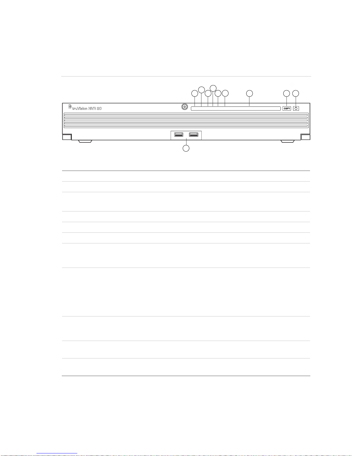
The NVR 20 – Front Panel
Figure 1: The NVR front panel
4
2
1
3 5
6
7 8 9
POWER ALARM TX/R/X HDD READY ARCHIVE
10
1 2 3 4 5 6 7 8 9 10 11 12 13 14 15 16
Table 1: Front Panel Elements
No Element Description LED Status Light
1 Po wer LED Shows that unit is powered Color = Normal
2 Alarm LED Shows if there are any alerts RED = Fault
OFF = Normal
3 T X/RX LED Shows unit is communicating across the network Blue Flashing
4 HDD LED Show read/write activity to the HDDs Red Flashing
5 READY Shows that the unit is full ready to function Blue = Normal
6 ARCHIVE Shows the status of the archive to USB operation. A
buzzer alarm will sound if an incompatible USB
device is detected.
7 Channel LEDs Shows the connected status of IP cameras to the
NVR 20, also provides indication of the record mode
of channel
Blue = Archiving
View or Scheduled Record
(No Event) = Blue
Event + View (no record) =
Red
View or Event + Record =
Purple
8 COPY Button When a USB Drive is connected to the USB Port on
the front of unit, pressing the COPY button initiates
archiving the most recent video to the USB drive
9 POWER Button Pressing this button for 3 seconds allows for a
controlled shutdown of the unit
10 USB 2.0 Ports
(2)
Used by the Copy button or via Remote Backup
managed through the Browser
TruVision NVR 20 User Manual 3
Archive LED glows BLUE
during operation
N/A
N/A
Page 10

The NVR 20 – Rear Panel
Figure 2: The NVR rear panel
Table 2: Rear Panel Elements
No Element Description
1 Reset Resets unit to factory defaults
2 RS-232 Used for connecting PC for troubleshooting
3 LAN 10/100/1000Mbps UTP Ethernet interface
4 eSATA For Future Use
5 RS-485 Switch For Future Use
6 RS-485
Connectors
7 Alarm In 16 alarm inputs (NO/NC)
8 Alarm Out 4 Relay outputs
9 GND Grounding point
10 POWER Plug Connection for power cord
11 Power Switch Power On/Off (use the Power Button on front of unit to turn power off to the
For Future Use
unit.)
4 TruVision NVR 20 User Manual
Page 11

Setting up the NVR 20
Installing the Hard Drives
Caution: Do not insert or remove drives with the NVR 20 powered on.
Note: This unit contains electrostatic-sensitive components. Before
handling the hard drives, make sure you are properly grounded to avoid
ESD damage.
1. Unpack the NVR 20 box.
2. Unpack the NVR 20 HDD box.
Note: HDDs in the shipping box are pre-mounted with their rail kits/caddy.
3. Use the key provided in the accessoies box to unlock the front panel.
4. Press the latches on both sides of the front panel to open it.
Figure 3: Opening the NVR 20
5. Install the hard drives per the schematic below. The first drive in position
number 1, the second in position number 2, and so on. Continue to install all
the hard drives in numerical order.
TruVision NVR 20 User Manual 5
Page 12
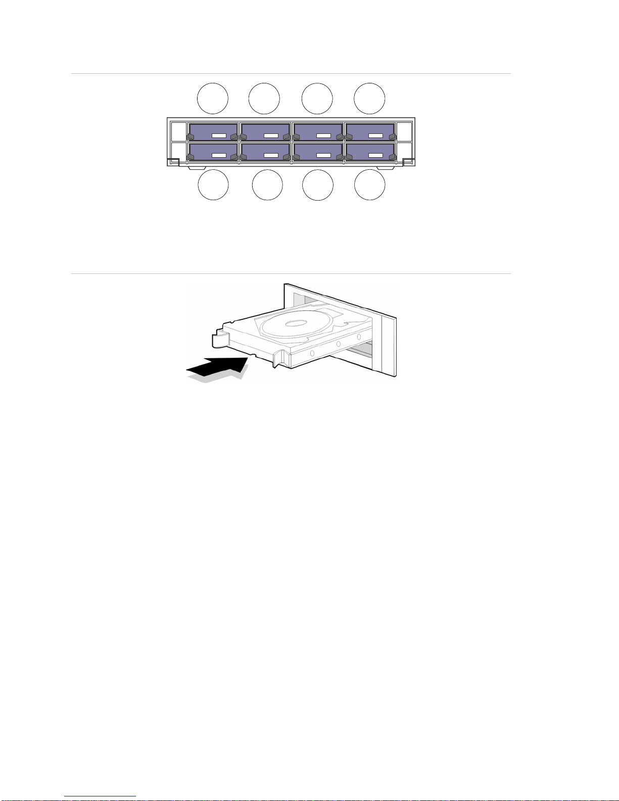
Figure 4: Hard Drive locations
1
2
6. Insert a Hard Drive into one of the hard drive bays until it has fully seated into
position. Repeat with the rest of the hard drives.
Figure 5: Insert the hard drive
3
4
5
6
7
8
7. Close and re-lock the front panel.
Note: The Hard Drives must be installed BEFORE powering on the unit. The
drives are defaulted to a single HDD group that is automatically ready to record
once IP cameras are added and configured with recording schedules.
Physical Installation of the NVR 20
1. Mount the unit on a shelf or in a 19” Rack (with attached rack ears) in a
suitably ventilated temperature controlled environment.
2. Connect the NVR 20 to your network with an Ethernet cable.
3. Connect the power cord and turn the power on.
Setting up the NVR 20 - Introduction
The NVR 20’s initial configuration should be completed using the NVR 20
Browser. This manual will show you the steps necessary to quickly configure a
fully operational recording solution.
Configuring a NVR 20 system requires:
1. Giving the NVR 20 an appropriate IP address with the TruVision Device
Finder tool.
6 TruVision NVR 20 User Manual
Page 13

2. Adding IP Cameras to the unit.
3. Configure the IP cameras.
• Depending on the model of IP camera, some IP Cameras may be
rd
fully configured by the NVR Browser or in the case of 3
Party IP
cameras it may be necessary to access the IP Cameras internal
web page.
• The majority of Interlogix brand cameras allow the unit to set video
streaming parameters of the IP Cameras.
4. Define the recording schedule for the IP Cameras. The recording modes
supported on the unit are:
• Schedule Recording
• Motion Recording (IP Camera’s internal activity detection)
• Alarm Input Recording
• The unit has 16 alarm inputs that can be used to trigger
recording of one or more connected IP Cameras.
• Some IP Camera models allow the IP Cameras internal
alarm input to trigger recording on the NVR 20.(Please
refer to the IP Camera Compatibility Document for a
complete listing of what capabilities are supported for
each IP Camera type).
5. Define any alarm output behaviors, local unit audible alerts, local-unit relay
outputs (4) as well as notifications to Interlogix’s TruVision Navigator video
management software.
6. All hard drives are pre-configured into a single recording group and allow
all connected cameras to record the same duration of video across all
cameras (i.e., all cameras will record for the same number of days)
• The browser allows for configuring specialized recording behaviors
such as duplicate IP Camera recording (Redundancy). Please see
the HDD Configuration & Management section for additional
information.
Configuration of the NVR 20 is optimized for out of the box operation. All IP
cameras added are defaulted to record continuously. All system events HDD
failure, video loss etc. are set to report to the TruVision Navigator software once
the address of the TruVision Navigator server is configured.
TruVision NVR 20 User Manual 7
Page 14

Minimum PC requirements for the Browser
The minimum hardware requirements for the Browser are:
Basic User Operation
• Live view in 9-Up w ith
4CIF/VGA Camera
OR
• Live view in 4-Up with up to 2.0 MpX Camera
• Intel E6550 Dual Core class Processor at 2.33
Ghz (4MB Cache)
• 1GB RAM
• HD Video Card with 256 MB
Minimum 1.5GB HDD Space for any saved video files
Keyboard, Monitor, Mouse
Windows XP, Windows 2000, Windows Vista, Windows 7
Internet Explorer 6.0, 7.0, 8.0
Power User Operation
• Live view in 9-Up
or higher with MpX Cameras
• Intel Core I5 750 Quad Core class
Processor at 2.66 Ghz (8MB Cache)
• 4GB RAM
• HD Video Card with 1GB
The NVR 20 has specific capabilities with respect to the number and mix of IP
Camera types. The camera types are:
• 4CIF/VGA resolution capable IP Cameras
• 1.3 MegaPixel resolution capable IP Cameras
• 2.0 MegaPixel resolution capable IP Cameras
• 3.0 MegaPixel resolution capable IP Cameras
• 5.0 MegaPixel resolution capable IP Cameras
In addition, the NVR 20 supports a variety of IP Cameras from different
manufacturers.
Important Note: Not all IP Cameras will have the same level of feature support.
These limitations often are limited by the different IP cameras and the protocol
they support.
The appendices at the end of this manual includes specific information on NVR
20 technical specifications as well as specific information concerning the unit’s IP
camera capacities and IP camera feature capabilities.
IP Device Auto-Discovery Tools
The NVR 20 can automatically “discover” a number of IP Cameras (different
makes and models) on a network. The NVR 20 can only discover devices that
are on the same network as the NVR 20.
For example, if the NVR 20 is on a network with an IP address of 192.168.1.82
with a subnet mask of 255.255.255.0, then the only IP cameras it can find will be
in the range of 1- 255 of the last octet.
8 TruVision NVR 20 User Manual
Page 15

Interlogix and other IP camera manufacturer’s provide auto-discovery tools that
make it easy to change the default IP address to conform to your network
addressing needs. It is strongly recommended you use these tools to quickly
identify and modify your IP device address needs.
Interlogix devices that support auto-discovery can be identified on the network
using the TruVision Device Finder. This simple tool allows you to view and
modify the IP address of any TruVision supported devices. This tool is included
on the NVR 20 Resource Disk included with your product. An introduction to the
tool is available in the Appendix.
Understanding the NVR 20 Browser
The NVR 20 browser page utilizes Windows Active-X controls on the Client PC
and delivers expected performance using Windows Internet Explorer 6.0 and
above.
Figure 6: The NVR 20 Browser Interface
When you launch Internet Explorer, you will be prompted to install Active X
controls. Please accept all prompts to load these drivers to ensure proper
behavior and operation of the web pages supporting the NVR 20. Once installed
you may login.
Default Login Username and Password
• User Name = admin
• Password = 1234
TruVision NVR 20 User Manual 9
Page 16

Initial Connection Page
From this page you can:
• View live video
• View playback video
• Save snapshots of images to your local PC
• Download video clips to your local PC
• Launch the Configuration pages that allow you to configure the device,
connection to IP cameras and event response behaviors (from alarm events
or device system alerts).
• Open NVR 20 searchable system and event logs.
Figure 7: Initial connection page
Alternatively, using Interlogix’s TruVision Navigator video management software
the user can view and respond to events from multiple NVR 20s or a mixture of
Interlogix TruVision DVRs and NVRs.
Note: PTZ and Brightness/Contrast controls are only available on specific
TruVision models of IP cameras.
Initial Config Tab Window
From this page you can quickly add IP cameras, configure recording schedules,
enable motion only recording modes as well as define the behavior of various
alarm inputs and outputs on the box. Additionally the browser allows
customization of system events affecting hard drive status, video loss, and more.
10 TruVision NVR 20 User Manual
Page 17

Configuration on the NVR 20 is optimized for quick connection to Interlogix’s
TruVision Navigator video management software.
There are two main configuration elements:
Remote Config – is the primary area where all IP camera functions are
scheduled and managed.
Local Config – this controls how users who only use the NVR 20 browser for
system operation may define where snapshots, video download and local
recording on the Browser’s PC are managed.
Figure 8: Initial Config tab window
The default view is the Remote Config view providing immediate access to
configure your IP cameras into the TVN 20.
This view shows the connected IP cameras connected to the unit. If this is the
first time, no cameras are populated.
Window features:
• Connected Camera summary detail
• D1-D16 are the available IP video channels which can be used with
supported IP cameras and supported encoders (depending on the model
ordered).
• The IP Addresses and port numbers of the connected cameras.
TruVision NVR 20 User Manual 11
Page 18

• Select the actual D1-D16 label to view additional detail on the camera in
the panel on the right. You can also click on this label to manually add an
IP Camera.
• Once cameras are added, by clicking in the main line of the camera, you
will launch the web page of the specific IP camera.
• The panel on the right is used to view the details of a selected camera from
the main list or for selecting an IP Camera channel in order to add manually a
specific camera.
• Quick Add is a button that will automatically find and allow the user to add in
the desired IP cameras with default settings. This works for camera models
that support Auto-Discovery.
• Configuration parameters is the path to customizing system recording,
event management and health monitoring behaviors.
12 TruVision NVR 20 User Manual
Page 19

Configuring the NVR 20
Using a PC running Windows Internet Explorer Version 6.0 or above, enter the
unit’s default IP address into the address bar and load the web page. The unit’s
default IP address is: 192.168.1.82. Login using the default username and
password.
• Default User Name = admin
• Default Password = 1234
Step 1: Set the IP Address for the NVR 20
Note: Before configuring the Network Settings, please contact your IT
Administrator to confirm the desired settings for your network.
• Select Config along the top feature bar.
• Select Configuration parameters from the lower right side of the screen.
• From the folder menu under Network Parameters select Network Settings.
Figure 9: Network Settings
• The NIC Type should be defaulted 10M/100M/1000M Auto.
• Under Device IP Address enter the desired IP address.
• The NVR 20 default Device Port should be set at 8000.
TruVision NVR 20 User Manual 13
Page 20
• Typical Subnet Mask will be 255.255.255.0 (default).
• The Default Gateway IP address usually can be set to the same as the IP
address except for the last device entry which is usually set to 1.
• The HTTP Port should remain at the default setting of 80.
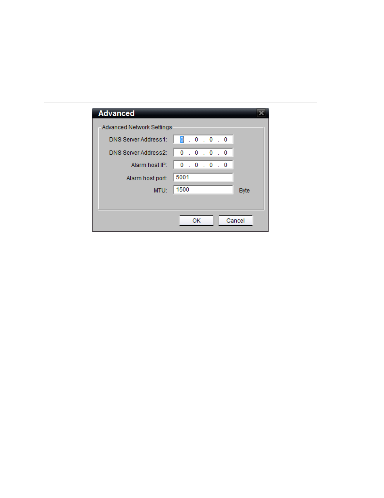
Figure 10: Advanced Network Setting
• Click the Advance button to confirm the following settings:
• MTU is set to 1500
Note: If Interlogix TruVision Navigator software is to be used please make sure
the following entries are completed:
• Alarm Host IP is set to the TruVision Navigator Software Server IP.
• Alarm host port is set to 5001.
• Click OK to return to the main Network Settings page.
• Click SAVE to save and apply these settings. The Browser will notify you that
the NVR 20 needs to reset. Please select OK.
If Multicast, DHCP, DNS Servers or specific MTU packet size are to be utilized
for your network please contact your IT Administrator. These settings can be
accessed via the Advanced button.
Step 2: Set Video Format for the NVR 20
Although we are dealing with IP video, to make sure the browser display delivers
the correct image size it is necessary to set whether the video format for your
region is NTSC or PAL.
14 TruVision NVR 20 User Manual
Page 21

• Click Configuration parameters on the lower right hand side of the
REMOTE CONFIG main page.
• On the left section….select Device Parameters > Device Information
• Go to the Video Format field and select either NTSC or PAL.
• Click Save.
Figure 11: Device Information
On the left section….select Device Parameters > Device Information
• Overwrite determines that recording will be circular and overwrite older video
with newer video. The setting should remain Yes for most users.
TruVision NVR 20 User Manual 15
Page 22

• HDD Number indicates the number of HDDs installed within the unit.
• Alarm Input Number indicates the total number of alarm inputs built into the
unit that are available.
• Alarm Output Number indicates the total number of alarm outputs built into
the unit that are available.
• Device Serial No. is the unit’s serial number.
• eSATA identifies an output connection that allows for connecting an external
eSATA storage device. At this time this feature is not available and will be
released in a later release of the firmware.
• Automatic IP camera connection should only be checked if you have a
single TVN 20 in your system. The feature will automatically detect all
discoverable IP cameras and upon logging out and then back in, available
cameras will be added until all available channels on the unit are occupied.
DO NOT use this feature if you have more than one TVN 20 on the same
network as you will risk having the same camera connected to two or more
TVN 20 units.
• Sync to PC time will perform a time-synch between the PC of the connected
Browser and the TVN 20 using the PC’s time. The time synchronization only
takes place when the button is pushed. The NVR 20 will automatically
perform a time synchronization to the IP camera every 5 minutes.
To save the changes you have made, press the Save button.
Note: Pressing the Default button restores Factory Defaults for the NVR 20.
Pressing the Reboot button immediately reboots the box while keeping the
network settings. Under normal conditions the only reason to reboot the unit is:
• Changing the IP Address, DHCP, PPPoE, Device Port of the NVR 20.
• Changing the Alarm Inputs state (NO/NC).
• Pushing a firmware update to the NVR 20.
• Restoring default settings.
• Importing a configuration from the external software like TruVision
Navigator.
A typical reboot can take between 45 to 75 seconds before full functionality is
restored.
16 TruVision NVR 20 User Manual
Page 23

Step 3: Set Daylight Savings Time and NTP Server
Settings
Daylight Savings Time
This is important for correct video recording.
• From the Device Parameters > DST Settings, to enable automatic daylight
savings adjustment click the checkbox Enable DST (the default behavior is
NOT enabled)
• Enter the correct dates and times for the time changes.
Figure 12: DST Settings
Note: DST Bias is a specific field for certain areas around the world where
daylight savings time adjustments are more than one hour. This setting allows
the system to adjust to these regions.
NTP
Time synchronization between IP devices is critical for effective and accurate
video recording. Many IP Cameras look for an NTP server or some other device
to synchronize their time to. Network Video Recorders like the NVR 20 are
interacting not only with other NVR 20’s but the many IP cameras that each is
carrying its own time. It is vital that all of these devices share a single common
time.
The NTP Server can be as simple as the Client/Server PC in an Interlogix’s
TruVision Navigator installation, or it may be a specific NTP server on the
network tasked with maintaining a unified network system time.
TruVision NVR 20 User Manual 17
Page 24

• From the Device Parameters Folder select NTP Settings element, in order to
enable and point the NVR 20 to the appropriate time server.
• Select the Enable NTP checkbox to establish an NTP server that the NVR 20
will point to. (Default setting is NOT checked)
• Enter the Server Address for the NTP Server; this may be an IP address or a
Domain Name.
• Enter the NTP Port address; most NTP Servers use the default port of 123.
• Set the frequency of time synchronization for the NVR 20 with the NTP
Server, the default is every 60 minutes.
• From the drop down list select the time zone where the NVR 20 resides, the
default is (GMT+00:00) Dublin, Edinburgh, London.
Figure 13: NTP Settings
• Sync to PC time will perform a time-synch between the PC of the connected
Browser and the TVN 20 using the PC’s time. The time synchronization is
only when the button is pushed. This should only be used if NTP is not
18 TruVision NVR 20 User Manual
Page 25

enabled. The NVR 20 will automatically perform a time synchronization to the
IP camera every 5 minutes.
Step 4: Adding IP Cameras
Adding IP cameras to the NVR 20 is at the heart and soul of the system. There
are two methods for adding IP cameras:
• Automatically via Auto-Discovery (using Quick Add function)
• Manually
Auto-Discovery automatically locates the IP address of IP cameras and inputs
the default connection parameters (User Name, Password, and Port Number). If
a camera does not support Auto-Discovery, the User can manually add cameras
without loss of capability.
Using the Quick Add function
Use the Quick Add button to locate Auto-Discovery compatible IP camera
devices. The unit will scan the local network and list all discoverable camera
devices. Use the check box to select those devices you wish to add to the
connected NVR 20.
Quick Add will only detect cameras that are on the same LAN. It is not able to
detect cameras that are on a VLAN. If Quick Add does not detect your cameras,
please follow the procedures listed under Alternative Add - Manual Process.
TruVision NVR 20 User Manual 19
Page 26
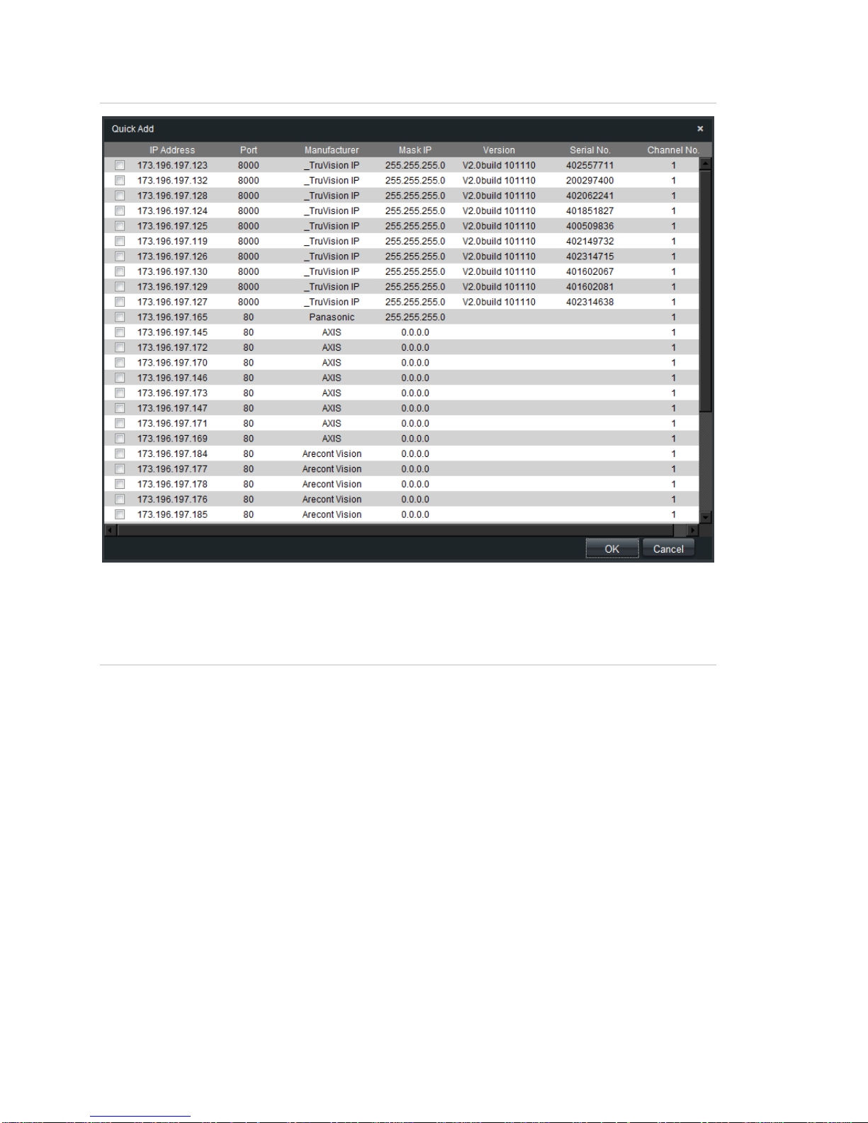
Figure 14: Quick Add Window
Select the devices you wish to add and Click OK. The system will return you to
the previous window this time populated with the selected cameras.
Figure 15: Populated Config Window
20 TruVision NVR 20 User Manual
Page 27

Clicking on the Channel No. for each line, the IP Camera Config panel on the
right will display additional details about the configured camera.
Please Note: The Online/Offline status will not automatically refresh its status
and may take a few minutes before its status will be available. Press F5 to
refresh the page.
Alternative Add – Manual Process
Should the desired IP camera not support Auto-Discovery or if other network
issues inhibit auto-discovery, the user can manually add cameras.
• Select the channel number (D1, D2, D3…..); this will allow the USER to
populate the IP Camera Config panel (on the right of the screen).
• Login Mode = IP (or Domain)
• Manually input the IP Address or Dormain.
• Select the IP camera/encoder manufacturer from the drop down list.
• Select the communication port used by the camera (per the IP camera
manufacturer’s specifications usually port 8000 or 80).
• Enter the IP Camera’s User Name and Password.
• Channel No. only applies if the device connected is a multi-channel encoder,
the default value of 1 should be sufficient for most installations.
• Press Modify to add the camera.
• The camera will show up in the list if the setup parameters are correct.
Step 5: Configure IP Camera - Device Settings
Depending on the IP Camera model, the IP Camera titles, on-screen display
(OSD), frame rate resolution and activity detection may be configured within the
NVR 20 Browser. In the cases where functionality within the browser does not
support configuration, the User can link to the IP camera web page and
configured the desired parameters.
There is a chart at the end of this guide that shows the current list of supported
cameras and their capabilities. Please check with your Interlogix’s representative
for the latest list of supported cameras.
TruVision NVR 20 User Manual 21
Page 28

Configuring Cameras via the NVR 20 – On Screen Time/Date/Titling
Fully Configurable Cameras
Figure 16: Display settings for fully configurable cameras
• Select Channel No:
• Click Show Name if you want the camera title to be overlayed on the video.
• Enter the desired camera name.
• Click Show Date and select the time format 12/24 Hour, Date Format and
also select Display Week if you want the Day of the Week to be displayed.
• Select the type of OSD display – the default Non Transparent & Non Flashing
is recommended.
• OSD Position allows the User to independently position the Time/Date/Day
display distinctly from the Camera Title. Press OSD Position > Settings to
bring up the OSD window. Simply click on the time/date or camera title
elements, click and drag each of them using your mouse, to the desired
placement within the image.
22 TruVision NVR 20 User Manual
Page 29

• The Copy button allows you to duplicate these settings to another camera to
speed configuration.
• Click Save to save these settings.
TruVision NVR 20 User Manual 23
Page 30

Configurable Cameras Only by the IP Cameras Web Page
Figure 17: Display settings by the IP cameras web page
IP Cameras (IPC) that do not support full OSD configuration will allow the User to
define a local (internal) camera title for easier identification of the camera. IP
Cameras that do not allow setting of OSD display, even though the TVN 20
allows identifying a camera title, this title is for user identification of the camera
but is not included as part of an On-Screen-Display (OSD) from the camera.
Note: Please enable the IP Cameras Time/Date and Title on-screen displays
from the Manufacturers Web Page. This is strongly recommended for evidence
collection purposes.
24 TruVision NVR 20 User Manual
Page 31

Step 6: Configuring IP Camera - Resolution Settings
Important Detail about Available Resolutions and their Matching Frame
Rates
Most IP Cameras have limitations on the available frame rates they can support
at different resolutions. Keeping track of this can be very complicated. We have
chosen in the Frame Rate field to list the Resolutions that support the various
frame rates.
Figure 18: Frame Rate Field
]
The example here shows a selection of UXGA (Resolution 1600x1200). The
Frame Rate dropdown shows
• Full frame rate is available for VGA, XGA and SXGA resolutions
• At frame rates 24(all) and below ALL resolutions are supported including the
UXGA resolution.
In this instance, if the desired resolution is UXGA, then the maximum available
frame rate is 24 images per second.
The above image also shows that when you select Customize for the Max
Bitrate, an additional field is available to manual set a target bitrate in Kbps.
TruVision NVR 20 User Manual 25
Page 32

Configuring Cameras via the NVR 20 – Video Streaming (Encoding)
Parameters
Fully Configurable Cameras
Figure 19: Encoding Parameters for fully configurable cameras
Under Encoding Parameters some cameras support more than one video profile
that may be used for normal, event and (low-bandwidth), sub-stream for live
streaming.
Figure 20: Encoding Parameters menu
When more than one encoding profile is available, it is necessary to select each
profile and set the configuration parameters below. Press Save after configuring
each profile before selecting another profile to configure. Repeat the steps below
for each configured encoding profile.
1. Select Channel No:
2. Under Encoding Parameters Select the stream you wish to configure.
3. Select the Stream Type - Video is the default, some cameras will support
both Video and Audio.
4. Select the desired Resolution from the drop down list.
5. Select the desired BitRate. The default is Variable.
26 TruVision NVR 20 User Manual
Page 33

6. Select the Max Bitrate for the camera from the available settings in the
drop down menu.
7. Select the desired Frame Rate from the drop down list box for the
camera.
8. Select the desired Video Quality from the available entries in the drop
down list box.
9. Press Save after all entries for the selected encoding profile have been
completed.
Remember to repeat these steps for each Encoding Parameter available.
Partially Configurable Cameras
Figure 21: Encoding parameters for partially configurable cameras
Cameras without full configurability will show the parameters reflecting the key
functionality of that manufacturers’ camera. Not all features of some
manufacturer’s camera are supported in the NVR 20.
If the NVR 20 supports multiple encoding parameters, follow the same steps for a
fully configurable camera.
Follow the steps for Fully Configurable Cameras based upon the options enabled
and choices available in the drop down lists.
Additional Information Bitrate Types
Variable Bitrates
• Select this method if you desire to optimize recording as the data rate
varies based upon the scene complexity.
• Use this especially for cameras where the background or scene activity
may be less intense.
TruVision NVR 20 User Manual 27
Page 34

• Any bitrate target set for these cameras is only a target and the effective
bandwidth can be 10-20% above the target and depends on the IP
Camera manufacturer and the amount of scene activity.
Constant Bitrates
• Use this when it is important for predictable network performance and
limiting the impact of video on the network.
• Under CBR, the data rate does not exceed the set limit.
Troubleshooting
What do I do if the selected IP camera is not fully configurable from the NVR 20?
As stated previously not all cameras that can connect to the NVR 20 support full
configuration from the NVR 20. On-Screen Display (OSD), some frame rate and
encoding parameters and video motion detection may only be configurable using
the IP Camera Manufacturer’s web page.
From the main Config page (REMOTE), in the listing of the IP camera, the user
can directly launch the IP Camera Manufacturer’s web page by clicking on the IP
address.
Figure 22: IP camera information page
You can now finish configuring the desired elements not available in the NVR 20.
Note: If a feature is configurable in the NVR 20, then configure it from the NVR
20. The setting in the NVR 20 will overwrite any changes made directly to the IP
Camera via the Manufacturer’s browser.
Step 7: Setting Up Recording Schedules - Introduction
The NVR 20 supports a robust set of scheduling capabilities which include
normal and event recording with up to 8 time periods per day. Recording
schedules can be copied across every day of the week and to multiple cameras
for fast entry. Recording schedules interact with the available encoding profiles.
28 TruVision NVR 20 User Manual
Page 35

Note: By default every camera added to the system is automatically enabled for
7x24 continuous recording.
The NVR 20 uses a maximum of two recording profiles (independent frame rate,
resolution, and bandwidth) with recording schedules. Not all listed IP cameras
support two recording profiles. Where the camera supports, the two possible
profiles are (check the IP Compatibility Chart for specifics):
• Main (Normal) - associated with Scheduled/Time-Lapse Recording
• Main (Event) – associated with Motion and Alarm Recording
• SubStream – available only for live view in multi-camera display through
the browser and Interlogix TruVision Navigator software (if supported by
the camera)
Table 3: IP Compatibility Chart
Record Mode Description
Time-Lapse or Continuous
Schedule Record
Motion Detection
Alarm Recording
Motion Detection
/ Alarm
Recording Main - Normal Main - Normal
Event recording triggered
by IP Camera motion
detection
Event recording triggered
by any of the NVR 20’s onboard analog alarm inputs.
With some cameras, the
digital alarm inputs from
the IP Camera may be
used
Recording is triggered
either if there is a motion
detection OR an alarm
input is triggered (ORGating)
Multiple Profile IP
Cameras (used
Profile)
Main - Event Main - Normal Main - Event
Main - Event Main - Normal Main - Event
Main - Event Main - Normal Main - Event
Single Profile
IP Cameras
Live Stream*
Main – Normal
(Substream if
available)
Recording is triggered only
Motion Detection
& Alarm
* If the IP Camera supports only a single encoding parameter in the NVR 20, only that stream is available for
Live Streaming
if there is motion detection
AND an alarm input (AndGating)
TruVision NVR 20 User Manual 29
Main - Event Main - Normal Main - Event
Page 36

Scheduled Recording Configuration
Follow the steps below to setup scheduled recording:
1. Configure Time-Lapse Recording (Schedule Recording).
2. Configure Motion Activated/Alarm Input Recording Schedules.
Figure 23: Scheduled Record window
The color bands show the enabled recording mode for the camera.
Scheduled = Blue Motion = Yell ow Alarm Input Only = Red
Motion OR Alarm = Purple Motion AND Alarm = Light
Blue
Command = Future Use
Step 8: Setting Up Recording Schedules - Sample
Configuration
Completing this sample configuration will familiarize you with the essential skills
needed to configure any camera for recording.
Camera 1 shall be record as follows:
30 TruVision NVR 20 User Manual
Page 37

• 00:00:00 to 06:45:00 hours in Motion Detection mode (Midnight to
6:45AM).
• 06:45:00 to 17:00:00 hours in Schedule Recording mode (Time-Lapse
from 6:45AM to 5:00PM).
• 17:00:00 to 24:00:00 hours in Motion Detection mode (5:00PM to
Midnight).
• This daily schedule will be applied for every day of the week.
• Copy this schedule to Cameras 1, 2, 3 and 4.
Begin Configuration
1. Select Scheduled Recording folder from the navigation window.
2. Select Camera 1.
3. Make sure the Enabled Recording option is checked.
4. Click on Settings button associated with the Record Time field.
Figure 24: Schedule Record window
5. Make sure All Day Recording is NOT checked.
6. Any day of the week may be selected in the Weekday drop down (we will
copy this to every day of the week later.
7. Click on Period1.
8. Enter 0:0 for the start time and 6:45 for the end time (you can enter the values
directly or use the selection buttons).
TruVision NVR 20 User Manual 31
Page 38

9. From the Recording mode drop down list, select Motion Detection.
Figure 25: Motion Detection selection
10. Select Period2.
11. Enter 6:45 for the start time and 17:0 for the end time.
12. From the Recoding mode drop down list, select Scheduled Recording.
Figure 26: Schedule Recording selection
13. Select Period3.
14. Enter 17:0 for the start time and 24:0 for the end time.
15. From the Recoding mode drop down list, select Motion Detection.
32 TruVision NVR 20 User Manual
Page 39

Figure 27: Motion Detection selection
16. At the bottom of the page from the Copy to: drop down list, select Whole
Week.
17. Press the Copy button to copy these settings to all days.
18. Click OK to complete this page and return to the Schedule Record Window.
Figure 28: Recording Schedule window
TruVision NVR 20 User Manual 33
Page 40

19. Observe the updated schedule.
20. Select the Copy to… button at the bottom of the page to copy these settings
to the desired additional cameras.
Figure 29: Schedule Record window
21. Pressing the Copy to… button opens a dialog box.
22. Select the checkbox for the desired cameras to receive the same schedule
(in this case 1-4).
23. Click OK the dialog box will close and return you to the Schedule Record
page.
34 TruVision NVR 20 User Manual
Page 41

24. To verify that the schedule was applied to the other cameras, select them
from the Camera selection box at the top of the page and observe the schedules.
25. Click Save to assign this schedule to the cameras.
Figure 30: The Copy to… dialog box
Step 9: Final Steps for Recording Schedules – Motion
Detection Trigger
In order for Motion Recording to be possible, motion detection must be enabled
on the desired cameras.
This is a simple two-step process:
1. Enable Motion Detection on the IP Camera.
2. Define the activation schedule for the IP Camera motion detection trigger.
For select IP Cameras, the NVR 20 can configure motion detection areas
(regions of interest) within the NVR Browser. For the other IP cameras, the NVR
20 incorporates a link to the IP camera’s web page to enable configuring motion
detection directly on the IP Camera.
TruVision NVR 20 User Manual 35
Page 42

Figure 31: Motion Detection window
1. Select Motion Detection folder from the navigation window.
2. Select Camera 1.
3. Make sure the Enable Motion Detection option is checked.
4. Click on the Area settings button (this button is available if the IP Camera
selected is supported in the NVR 20 for motion area definition). A settings
dialog box opens.
If the IP Camera does not support this function within the NVR 20, then the
Settings button will not be accessible. The user will need to access the IP
camera’s web page to configure Motion Detection Regions of Interest (ROI).
36 TruVision NVR 20 User Manual
Page 43

Figure 32: Area Settings window
6. Select the Start Draw check box.
7. Using the mouse, click and drag up to 4 areas.
8. Click on the desired Sensitivity setting.
9. Click OK to accept the settings.
10. The display will return to the Motion Detection page.
TruVision NVR 20 User Manual 37
Page 44

Figure 33: The Arm Schedule window
11. Select Settings from the Arm Schedule to define a schedule for motion
events.
12. The default setting is motion detection is enabled 7 x 24.
13. The User can define a specific schedule for when motion detection streams
are available to the system.
14. Up to 8 Enabled periods may be defined with an On time and an Off time.
15. The daily schedule can be copied to other days or the entire week using the
Copy button.
16. Click OK, the browser will return to the Motion Detection page.
Note: These settings are available regardless of how motion detection areas are
defined in the camera (by the NVR 20 or at the Camera).
Configuration Note: If a Recording schedule with Motion Detection periods is
defined, is it necessary to have the motion activation schedule match the
Schedule Recording settings?
Matching the schedules provides for more precision in how video may be
recorded and viewed when two recording streams are supported. Normally,
Schedule Recording (Time-Lapse) will be at a lower frame rate and perhaps
38 TruVision NVR 20 User Manual
Page 45

lower image resolution than Motion Event recording which is typically at higher
frame rates and resolution settings.
The default setting when motion is activated for a camera with the event
schedule set at 7x24 hours will increase the amount of storage on the system
during periods when Schedule Recording (Time-Lapse) occurs without motion
detection set to the same schedule.
Recording Mode Motion Detection Set 7x24 Motion Detection Not Active
during Schedule Recording
Periods
Scheduled (Time-Lapse) During motion detection –
cameras will be recorded at
the Main (Event) rate
Motion/Event Recording Mode Recording at Motion/Event
Record Rate
Live Viewing Live viewing during an event
will be at the Motion/Event
settings
Recording will be at the timelapse rate
Recording will be at the timelapse rates
Live viewing if motion/event not
active during Scheduled
Recording (Time-Lapse)
periods will be a the time-lapse
rate
17. From the main Motion Detection page select Linkage: Settings to define the
NVR 20’s response to a Motion Event.
Figure 34: The Alarm Trigger Mode tab
18. Under the Alarm Trigger Mode tab select Audio Warning to trigger a local
box audible upon an event.
TruVision NVR 20 User Manual 39
Page 46

19. Upload to Center should be checked for Interlogix TruVision Navigator
notification.
20. Trigger Alarm Output to fire one or more of the NVR 20’s alarm outputs.
21. Email Linkage if you want the event to send off an email.
22. If Trigger Alarm Output is enabled, the user can switch one or more of the
Alarm Outputs under the Analog Alarm Output tabs (A->1 thru A->4).
Figure 35: The Trigger Recording tab
23. In order to enable recording for this event, select the Trigger Recording tab
to define which camera(s) will be recorded.
24. When satisfied, click OK to return to the main Motion Detection window.
25. Make sure SAVE is pressed to save these settings.
26. Make sure you press SAVE after each camera is configured.
40 TruVision NVR 20 User Manual
Page 47

Alarm Inputs
The NVR 20 includes 16 alarm inputs that may be used to trigger specific camera
recording, activate local NVR 20 relays and audible notifications, as well as send
remote event notifications via email or to video software management programs
like Interlogix’s TruVision Navigator software.
From the main Configuration page select Alarm Parameters folder and the
Alarm Input Settings option to define the NVR 20’s 16 alarm input’s behaviors.
There are two types of alarm inputs that are configurable.
• The 16 on-board inputs.
• For select IP cameras, the unit can also respond to the inputs on-board to
the camera (Please see the Advanced Alarm Input & Output Settings
section of this manual for additional information).
On-Board Alarm Inputs are defined as: A->1 to A->16.
Select the desired Alarm Input
1. If desired give the Alarm Input a local name within the NVR 20.
2. Select the electrical connectivity of the input as a Normally Open (NO) or
Normally Closed (NC).
3. To enable the alarm input, select the checkbox Alarm Handle.
TruVision NVR 20 User Manual 41
Page 48

Figure 36: Alarm Input Settings
The default enabled (Arm) schedule is 7x24 for every day of the week.
Follow the same procedure as for Motion Detection schedules to set specific On
and Off periods for the alarm input.
You may copy the schedule to specific days via the Copy to… drop down.
Once you have finished the schedule, press OK to return to the main alarm input
window.
42 TruVision NVR 20 User Manual
Page 49

Figure 37: Arm Schedule
Press the Linkage Method Settings button to configure the behavior of the
alarm input when triggered.
Figure 38: Alarm Trigger Mode tab
Under the Alarm Trigger Mode tab select:
TruVision NVR 20 User Manual 43
Page 50

• Audio Warning to trigger a local box audible upon an alarm.
• Upload to Center should be checked for Interlogix TruVision Navigator
notification.
• Trigger Alarm Output to fire one or more of the NVR 20’s alarm outputs.
• Email Linkage if you want the event to send off an email.
• If Trigger Alarm Output is enabled, the user can switch one or more of the
Alarm Outputs under the Analog Alarm Output tabs (A->1 thru A->4).
In order to enable recording for this event, select the Trigger Recording tab to
define which camera(s) will be recorded for this event.
Figure 39: Trigger Recording tab
When satisfied, click OK to return to the main Alarm Input Settings window or
select the PTZ Linkages tab if you wish to enable PTZ preset, pattern or patrol
behavior for PTZ cameras.
IMPORTANT NOTE: PTZ Linkage behaviors are not supported in the current
product version. Please see the release notes associated with any firmware
updates for announcement when the features will be supported.
If you select the PTZ linkage tab, you can define for each specific PTZ camera a
pre-programmed PTZ camera Preset, Patrol or Pattern.
Note: The setting of presets, patrols and patterns are a function of the specific IP
camera manufacturer’s web page.
44 TruVision NVR 20 User Manual
Page 51

Once you have completed your desired entries, select OK to return to the main
alarm input settings page.
Make sure SAVE is pressed to save and apply these settings.
Make sure you press SAVE after each alarm input is configured.
Figure 40: PTZ Linkage tab
TruVision NVR 20 User Manual 45
Page 52

Additional System Elements - Overview
Please see Chapter 2 - Advanced Topics section of this manual for additional
information on the following NVR 20 capabiltities:
Video Lost
Every camera that is added to the system will by default be set for video lost
detection. Video loss detection reporting may also be scheduled.
Video Tamper
This feature is available on specific camera models and provides notification in
the event if a camera is repositioned, the video is obscured or if the camera is
being blinded by bright lights.
Video Record Masking
This feature is available on specific camera models and allows the recorded
video to include a blacked out areas necessary to maintain privacy when
cameras are subject to local regulations concerning cameras located in public
places.
Exception Parameters
Please see the Exception Parameters - System Health Monitoring section on
page 84 of this manual for additional information.
System capabilities include the detection and notification of various system
health elements designed to protect the proper operation of the unit. These
events can trigger local audible on the NVR 20 unit; they can trigger the local
alarm outputs on the unit and can be sent to video management software such
as Interlogix’s TruVision Navigator software.
The type of events includes:
• HDD Fault/Failure
• IP Address Conflicts
• IP Camera Off-Line Notification
• HDD Read/Write Failures
• Network Fault
Account Management /User Rights
Please see the Account Management (Users) section on page 62 of this
manual for additional information.
46 TruVision NVR 20 User Manual
Page 53

The Browser supports three types of Users on the system. One administrative
user with full rights to the entire system and two additional levels of User that can
be custom configured to determine what rights the user has to access specific
cameras for live video, recorded video, manually recording video and more.
Note: If you change the default password for the Administrative User, this
password must be used in Interlogix TruVision Navigator software if TruVision
Navigator is to connect and manage the NVR 20.
Additional Network Settings: DDNS, DNS, PPPoE and Email
Please see the Additional Network Settings section on page 100 of this
manual for additional information.
DHCP and DNS
• The system supports DHCP for dynamic IP addressing
• DNS Servers for Domain Name resolution
DDNS and PPPoE Services
These services allow connectivity via the Internet, enabling the unit to be
accessed remotely across the Internet.
Email
The unit can send event and system health notifications via email including
support for authentication and SSL security. Up to 3 recipients may be defined
for email notification
HDD Configuration and Management
Please see the HDD Configuration & Management section on page 54 of this
manual for additional information.
The NVR 20’s hard drives are fully configured and ready to record upon turning
on and adding IP cameras. The default setting for the unit’s hard drives will
provide the same duration of storage for all connected cameras. Cameras are
recoded on a first-in, first out basis. All hard drives are configured in a single
HDD group. Failure of a hard drive does not prevent all of the remaining hard
drives to continue to record and retain the desired video.
The system supports advanced hard drive behaviors such as the ability to:
• Set up cameras for redundant recording. Unlike hard drive mirroring this
enables one or more drives to specifically duplicate the recording of
priority cameras.
TruVision NVR 20 User Manual 47
Page 54

• Hard Drive Groups where the benefit is that if some cameras need longer
storage than others, distinct hard drive groupings may be created with
specific cameras assigned to those groups.
Remote Firmware Update
Please see the Remote Update section on page 108 of this manual for
additional information.
The NVR 20 is remotely upgradable to the latest firmware versions. Future
firmware versions will provide enhanced capability especially in the support of
newer models of IP cameras in addition to enhanced features and bug fixes.
Please check with your Interlogix representative or business partner regarding
software/firmware service agreements that will keep your system up-to-date.
RS-232 and RS-485 Ports
The unit includes both RS-232 and RS-485 ports.
• Currently, the RS-232 ports are only available for advanced unit
troubleshooting. Additional feature capability is expected in the near
future.
• The on-board RS-485 ports are for future use.
IP Camera Alarm Inputs/Outputs Control
The unit, via specific IP Camera models, has the ability to respond to alarm
inputs, to trigger alarm outputs and to control RS-485 ports that may be resident
on the IP camera. This allows an alarm input on any connected camera to
trigger an output on another IP camera.
Integration with Interlogix’s TruVision Navigator
Software
Many of the default settings in the NVR 20 are designed to speed the units’ setup
with TruVision Navigator software. By way of example, all health monitor events,
any enabled alarm input event, motion event are defaulted to report to TruVision
Navigator. The default connection ports are already set in the NVR 20 to support
TruVision Navigator. It is necessary to configure via the Network Parameters >
Network Settings > Advance button, the specific IP address of the TruVision
Navigator Server for live, playback, event monitoring and remote configuration of
the NVR 20 from TruVision Navigator.
If Interlogix TruVision Navigator software is to be used please make sure the
following entries are completed:
48 TruVision NVR 20 User Manual
Page 55

• Alarm Host IP is set to the TruVision Navigator Software Server IP
• Alarm host port is set to 5001
• Click OK to return to the main Network Settings page
• Click SAVE to save and apply these settings. The Browser will notify you
that the NVR 20 needs to reset. Please select OK.
Figure 41: The Advanced Network Setting window
Note: Although a majority of the key elements of the NVR 20 can be configured
from TruVision Navigator, some key elements such as IP Camera AutoDiscovery, Hard Drive Groups and IP Camera input behaviors can only be
configured on the NVR 20 at this time.
TruVision NVR 20 User Manual 49
Page 56

Local Browser PC Settings
From the Config tab the user can configure the main settings for IP cameras
listed under Remote Config as well as set the behaviors for the Client PC that is
connecting to the unit via the browser.
The settings on the Local Config page ONLY apply to the browser connection via
that specific client PC (local to that PC). The default settings should be
acceptable for most normal usage. Please refer to the section Remote Record
& Video Download in the NVR 20 Advanced topics area of this manual.
The settings of specific interest may be the default file paths for saving recorded
files (manual recording), capture snapshots live (preview), capture snapshots
from playback, and downloading video clips wherein the User may wish to
change the default storage locations. Please note, the ability of users to
download and take snapshots is managed under the Account Management
settings (Remote Config).
Figure 42: The Config tab
50 TruVision NVR 20 User Manual
Page 57

Live Viewing and Playback Viewing from the
Browser
The Live Viewing Browser Page
Figure 43: Live Viewing Browser Page
10
1
2 3 4 5 6 7 8
Table 4: Live Viewing Features
Item Name Description
1. Connection
Tree
The left hand panel shows the configured IP cameras on the NVR 20.
Clicking on an individual camera’s arrow icon will load it into the current
display window. Depending on the image size and mega pixel rating of the
camera, loading the camera may take several moments.
2. Live Display
modes
The user can display cameras live in a 1-Up, 4-Up and 9-Up View. In a
multi-screen mode, the user can simply click the NVR 20 device icon at the
top of the camera list to automatically load as many cameras in the display
(4 in 4-Up, and 9 in 9-Up).
To load a camera into a specific tile of a multi-up display, the user just
highlights the tile and then clicks the desired camera in the list.
11
12
9
3. Stop
Stops all streaming
Streaming
4. Capture Takes a snapshot of the currently highlight camera an d saves it to the local
browser PC.
5. Start
Allows local PC recording of all cameras active in the display.
Recording
TruVision NVR 20 User Manual 51
Page 58

Item Name Description
6. Stops
Stops manual recording of the displayed streams.
Recording
7. Previous
Page
8. Next Page
Allow the user to sequence through the available cameras. If the display is
in 1-Up mode the cameras are sequenced in order with each click of Next
and Previous Page elements. If the first camera loaded was Camera 5,
pressing the Next Page button will advance back to Camera 1 and then
each successive Next Page button click will advance to Camera 2, 3, 4 etc.
If the display is in a multi-up display, pressing next will sequence through
numerical groupings (in 4-Up, Cameras 1-4, 5-8 etc.)
9. Audio If the camera is capable of supporting audio and audio is enabled for that
camera on the NVR 20, the user can turn on audio.
Clicking the arrow key brings up the audio volume control
10. Full-screen The display can be expanded to screen by pressing the Expand button in
the upper right hand corner of the display.
11. PTZ
Controls
The current version of the NVR 20 does not support PTZ control. This will
become available in a subsequent firmware release. Please check with
your Interlogix representative or business partner for the latest firmware
capabilities.
12. Picture
Controls
These camera controls are only available for select IP Cameras, Please see
the IP Compatibility Chart for the listing of cameras that support this feature.
52 TruVision NVR 20 User Manual
Page 59

Playback Browser Page
Figure 44: Playback Browser Page
7
13
1
2
3
Table 5: Playback Browser features
item Name Description
1. Connection
Tree
The left hand panel shows the configured IP cameras on the NVR 20.
Clicking on an individual camera’s arrow icon will load it into the current
display window.
2. Playback
Play/Pause, Stop, Frame Reverse, Frame Advance, Fast Forward
Controls
3. Video
A graphical display of the selected video
Timeline
4 5 6
12
11
10
9
8
4. Snapshot Takes a snapshot of the currently highlig ht camera and saves it to the local
browser PC.
5. Save Saved the selected video to the HDD.
6. Audio Displays a Volume control slider if audio is available.
7. Expand
Screen
8. Recording
Mode LEDs
TruVision NVR 20 User Manual 53
The display can be expanded to screen by pressing the Expand button in
the upper right hand corner of the display.
Indicates a Scheduled Recording of Alarm Recording. Schedule Recording
(Time-lapse) video is in blue and Motion or Alarm Input recording is in Red.
Page 60

item Name Description
9. BackUp
Button
10. Down
Button
11. Go to
Button
12. Day and
Time
Search
13. Channel
Status
This button allows the User to backup video segments on the NVR 20 to a
USB 2.0 and above memory stick that can be plugged directly into the NVR
20. The BackUp process can include downloading a copy of the NVR 20
Mini-Player.
This button allows the User to copy video segments from the NVR 20 to the
local PC.
Click the Go To button to enter a specific time to go to for playback.
Day Search: Select the Date to view video from and press the Search icon.
Day and Time Search: Select the Date to view video from and click the Go
To button to enter a specific time to go to for playback.
During playback, the status display shows the current playback IP camera
channel, the date and time of the video in the display and also the playback
speed.
Searching for Video
The process for searching for video is:
• Select the camera that you wish to search for video on. Only one camera
may be played back at a time.
• Select the day you wish to view video (Day-Search) from OR for the specific
day enter a specific time (Time-Search) to localize the search.
• Press Search (or GO to, if time range search). The video is loaded in the
timeline below the video display window. Schedule Recording (Time-lapse)
video is in blue and Motion or Alarm Input recording is in Red.
• The User controls the display via the Playback controls. The available
controls are:
• Play/Pause
• Stop
• Fast Forward (multiple steps …2x, 4x, 8x)
• Frame Advance
Note: Rewind is not supported in the browser.
• The User can also control where playback time is by placing their mouse in
the time bar and dragging the time display to the desired placement in the
vertical pointer. As the time bar is move across the vertical pointer, the time
updates so the user can see the current time under the vertical pointer.
Day Search
Select the Date to view video from and press the Search icon.
54 TruVision NVR 20 User Manual
Page 61

Day and Time Search
Select the Date to view video from and click the symbol to enter a specific time to
go to for playback.
After entering the desired time, press the Go to button.
TruVision NVR 20 User Manual 55
Page 62

Chapter 2
NVR Advanced Topics
Summary
The following sections contain additional detailed information on the NVR 20.
HDD Configuration & Management
The NVR 20 offers a robust set of configuration options for video storage. Core
to this robustness is the ability to partition the hard drives into one or more
independent Hard Drive Groups consisting of one or more of the available hard
drives. The storage combinations include:
Recording Type Description
1 Normal HDD Recording
(Unit Default Configuration)
2 Redundant Camera Recording Allows specific cameras to be recorded on two different
3 Independent Hard Drive Recording
Groups
All recording methods have the advantage that if a drive fails, only that drive’s
data is potential at risk. The unit will continue to record to the other drives
without user intervention in the event of one or more hard drive failures.
All cameras share the full available hard drive storage
on the unit
Hard Drive Groups
Specific cameras can be assigned to specific Hard
Drive Groups typically in the case where some cameras
may need to be stored for different periods of time.
Hard Drive Groups
Normally, all hard drives in a system are associated into a single volume or hard
drive group. The NVR 20 allows the user to sub-divide the available hard drives
into more than one grouping. Any number of hard drives may be configured in
each group to the maximum allowed by the device. This allows for specialized
recording behaviors as detailed below.
56 TruVision NVR 20 User Manual
Page 63

Normal HDD Recording
This is the default configuration for storage on the NVR 20. All recorded video is
stored on a first-in, first-out basis and all drives record video sequentially on the
drives. It is important to note that all cameras are stored for the same number of
days regardless of the data rate configured for the cameras.
Redundant Camera Recording
This is a specialized configuration of the hard drives and utilizes the creation of
an additional Hard Drive Group. Unlike typical redundancy that duplicates data
on the hard drive, the NVR 20 provides camera specific redundancy. In this
case, the user defines the specific cameras where the need is to duplicate
recording on independent hard drive groups. For example: the system has 16
cameras, but 5 cameras it is desired to provide redundant recording – recording
for these specific 5 cameras is duplicated on different Hard Drive Groups.
Independent Hard Drive Groups
Another specialized configuration of the hard drives supported by the NVR 20 is
completely independent hard drive groups. In this instance, for example, in a 16
camera unit:
• Cameras 1-10 are in a hard drive group 1 (HDD Group 1)
• Cameras 11-16 are in hard drive group 2 (HDD Group 2)
Cameras 1-10, for example, only require 14 day storage. However, Cameras 1116 require 30 days storage. By sizing the number of hard drives in each group to
meet the desired storage duration the user can easily meet the recording
objective.
Normal Recording Steps
The default setting for the unit is with all available hard drives configured in a
single group shared by all connected cameras. No additional action is needed by
the User.
Understanding the HDD Settings options:
Field Title Description
HDD No.
Capacity (MB) Shows the capacity of the hard drive
Free Space (MB)
The row identifies the capabilities, status and options for this specific hard
drive
If the drive has not been filled yet, it will show available free space in MB. “0”
Free Space means the drive is in Overwrite mode (provided overwrite was
specified for system recording)
TruVision NVR 20 User Manual 57
Page 64

Normal or Standby.
Status
Type All hard drives are Local within the box. A future release may support
Normal means data is being read/written to the drive.
Standby means the drive is spun down to save energy since no data is being
read/written to the drive.
attached eSata drive extension to the box.
HDD Group
Attribute The available settings are: Read-Write, Redundant, Read. Normal operation
Figure 45: HDD Settings
Shows which hard drive group the drive is associated with. Up to eight (8)
Hard Drive Groups may be defined. Default setting is HDD Group 1
for a drive is Read-Write.
Use the Redundant setting if the drive is the destination for duplicate camera
recording.
Read designates the drive as read-only. This setting is only used if there is
data on the drive that you do not want to be overwritten or you are setting up a
record-till-full and stop operation.
TIP: The HDD Group and Attribute fields are not normally viewable in the
Window unless the scrollbar is moved to the right to expose the fields.
Additionally, to view the settings in these fields better, the User will want to
expand the field by placing their cursor at the field title left border and dragging to
review more data in the field. This is similar to what is done inside of typical
spreadsheets.
Please note: If you have changed the default hard drive configuration and wish to
restore the normal hard drive configuration, press the Default button and this will
return your unit to the factory defaults for all settings including the HDD Group
configuration. None of your existing video data will be lost.
58 TruVision NVR 20 User Manual
Page 65

Redundant Camera Recording Steps
1. Navigate to the HDD Settings page from Main Browser Page: Click
Config > under Remote Config area, select Configuration parameters
and then select the HDD Settings option in the Navigation window
Figure 46: Remote Setting
2. Click on the checkbox for the desired Hard Drive that you want to make
the redundant drive.
3. Select the HDD Group field and select a new HDD Group number from
the one defined for the normal drive (typically HDD Group 02).
TruVision NVR 20 User Manual 59
Page 66

Figure 47: HDD Settings with drop-down menu
4.
SelecttheAttributefieldandfromthedropdownandselectRedundant.
5. Press the HDD Group attribute button near the bottom of the page this will
open a dialog box where you can define which cameras will be
redundantly recorded on the selected drive group.
60 TruVision NVR 20 User Manual
Page 67

6. Select the Redundant Hard Drive Group number (HDD Group 02).
Select the checkbox for each of the cameras to be redundantly recorded.
HDD Group 02 Redundant Drive(s)View
(Cameras D2, D3, D4, D8, D9 are checked for
redundant recording)
HDD Group 01 View
(Make sure that the same cameras (D2, D3, D4,
D8, D9) are also checked for recording)
NOTE:Make sure the same cameras are also checked for HDD Group 01.
7. Press Ok which will return you to the previous screen.
8. Press Save to save your settings.
Independent Hard Drive Group Steps
1. Navigate to the HDD Settings page from Main Browser Page: Click
Config > under Remote Config area, select Configuration parameters
and then select the HDD Settings option in the Navigation window.
2. Click on the checkbox for the first hard drive that you want to make an
independent storage group from the main HDD Group 1.
3. Select the HDD Group field and select a new HDD Group number from
the one defined for the normal drive (typically HDD Group 02).
4. Make sure the Attribute field for the selected and from the drop down is
set to Read-Write.
5. Repeat this process (Steps 2-4) for each additional hard drive that you
want to assign to this group.
TruVision NVR 20 User Manual 61
Page 68

6. Press the HDD Group attribute button near the bottom of the page
this will open a dialog box where you can define which cameras will be
assigned to this independent recording hard drive group.
7. Select HDD Group 01 from the drop-down and check the cameras
required to be recorded by this group.
HDD Group 1 View
(Cameras D1-D9 are checked for recording to
HDD Group 1)
HDD Group 2 View
(Cameras D10-D14 are checked for recording to
HDD Group 2)
Select HDD Group 02 from the drop-down and check the cameras to be
recorded in this group.
Note: Whenever you add a camera by default it is included with HDD
Group 1.
8. Press Ok which will return you to the previous screen.
9. Press Save to save your settings.
10. Repeat steps 2-10 for each additional Hard Drive Group you wish to
create.
Read Only Attribute
By changing the hard drive attribute to Read only, the specified drive can no
longer be written to and the video stored there will remain until the drive is
formatted or the Read-Write attributed is applied.
62 TruVision NVR 20 User Manual
Page 69

Formatting Drives
Typically the only reason to format a drive is when you want to erase all video on
the drive or as part of a troubleshooting tip to verify if a drive is faulty.
From the HDD Settings page select the checkbox for each drive that you wish to
format or the Select All checkbox if you wish to reformat all drives. Then press
the Format button. The HDD formatting status area will show the status of the
reformatting process. Once the process is complete a notification window will be
displayed.
Drive Replacement
If a drive needs to be replaced, the replacement part number is:
TVN-20XX-HDD-2T.
This part number includes the drive and the drive caddy. The delivered drive is
formatted and ready to be inserted into the unit.
WARNING: Make sure that the NVR 20 is powered OFF, BEFORE removing or
replacing drives.
TruVision NVR 20 User Manual 63
Page 70

Account Management (Users)
Introduction
The Browser supports three types of Users on the system. One administrative
User with full rights to the entire system and two additional levels of Users with
specific rights to camera and system features. The two additional user
categories are:
• Guest
• Operator
These two user groups have a default set of capabilities; however, these can be
modified to fit your needs. These capabilities will apply to all users you assign to
these user groups. There is only one (1) admin user assigned to a system.
The default Admin login is:
User Name: admin
Password: 1234
Caution: You can change the default admin user’s password. However, if you
are using TruVision Navigator software, the device login user and password is
the admin account defined on the NVR 20. If you change the default password
on the NVR 20, you must make sure TruVision Navigator also uses the same
password.
Account Management is found under CONFIG>Remote Config>Configuration
parameters>Account Management.
64 TruVision NVR 20 User Manual
Page 71

Figure 48: Remote setting window
The created users are found displayed in the top window of the display:
TruVision NVR 20 User Manual 65
Page 72

The lower section shows the rights established for the highlighted user:
Adding Users
To Add a new user:
Press the Add button which will bring up the User Information window
1. Enter the new users name at the User Name field.
66 TruVision NVR 20 User Manual
Page 73

2. Enter and confirm the Password assigned to that user.
3. Define the Priority (user group), the available choices are Guest or
Operator.
4. Optional security feature allows the user account to be bound to either a
specific IP address and or a specific computer based upon MAC address.
If an IP address is entered, the user can only sign on from a computer with
that specific IP address. If the user account is bound to the MAC address,
the user can only sign on from a computer with that specific MAC address.
Press OK to return to the main Account Management page.
5. For each User group define what privileges and system capabilities they
can access via the Privileges section (for more detail on these options,
please see below)
6. After making the desired selections press Save.
User Name and Password are case sensitive.
The Modify button brings up the User Information page for the specific user
should any of the individuals entries need to be updated.
To delete a User, click on the User’s row and press Delete. Important Note: The
admin user cannot be deleted.
Managing User Rights
The Administrator account has full access to all unit capabilities. There is no
ability to restrict the Administrators rights.
For the two types of User groups, the system provides default settings that you
can accept or modify as desired to meet your operational goals. The basic
difference in the default settings is the Operator can view live (preview) and
playback, while Guest can only playback.
TruVision NVR 20 User Manual 67
Page 74

OPERATOR GUEST
These capabilities are completely modifiable.
Detail View of User Privileges
“Remote” means that the browser is able to access and control the selected
function.
Privilege Name Description
Remote Playback Ability for User to conduct video playback from the Browser
Remote Preview Ability for User to view live video from the Browser
Remote Manual Recording Ability for User to manually initiate recording on the PC using the Browser
Remote Log Queries Ability for User to view and inspect the NVR 20’s event/system logs from the
Browser
Remote Shutdown/Reboot Ability for User to activate the REBOOT command from the Browser
Remote Configuration Ability for User to make setting changes under the Configuration parameters
area:
• Device Parameters
• Alarm Parameters
• Exception Parameters
• Account Management
• Network Settings
In addition, the ability to add, modify or reset IP cameras is controlled under
this option (Remote Config Page).
Remote Advanced Management Allows User the ability to remotely format the hard drives and configure HDD
groups.
Remote Channel Management Ability for a User to add, delete, change or modify IP camera settings from
Remote Alarm Control Future Use
Remote PTZ Control Control PTZ from the Browser page
68 TruVision NVR 20 User Manual
the main Remote Config page and from the Config Parameters pages.
Page 75

The expand button associated with some of the entries expands to show the
individual camera’s configurable under the option.
For each User group you can individually for each user option what cameras may
be accessed.
TruVision NVR 20 User Manual 69
Page 76

Advanced Camera Settings
In addition to common IP camera capabilities such as motion detection,
depending on the support camera some additional features may be available. If
they are available for your particular connected camera, these additional options
will be available.
• Video Tamper
• Video Live and Record Masking
• Alarm Input from Camera Event Trigger
• Alarm Input from Camera to Camera Alarm Output
These additional capabilities are explained below:
Video Tamper
This feature provides means for notification under the following conditions:
• Attempts to shroud, block or obscure the video by means of placing
something in front of the camera lens.
• Attempts to “blind” the camera by shining a bright light into the lens.
The feature is engaged by defining the area that will detect attempts to inhibit the
video. In addition, the feature can be scheduled for when it is active via a weekly
schedule, as well as the type of notification response when an incident is
detected. These response actions include triggering local audible on the NVR
20, local alarm outputs on the NVR 20, Email notification, Notification to Interlogix
Navigator software and in special cases activating camera alarm outputs.
The steps to utilize this feature:
1. Select the Video Tamper selection from the navigation area
70 TruVision NVR 20 User Manual
Page 77

2. Select the desired camera to configure from the Channel No drop down
list.
3. Click the Enable Video Tampering checkbox.
4. Select the Settings button from the Area settings box.
TruVision NVR 20 User Manual 71
Page 78

5. Click the Start Draw checkbox and using your mouse select a single area
that is in the area of concern for video tamper. The feature will only allow
creating a single detection area.
• If you are not satisfied with the drawn area, please press the Clear
All button and start over.
6. Select the desired sensitivity level from the Sensitivity control by clicking
your mouse at the desired point on the slider bar. The standard setting is
Medium.
7. Click OK to return to the main configuration page for Video Tamper.
8. The default enabled schedule for Video Tamper is 7/24. If you want to
enable the feature based upon a specific schedule press the Settings
button from the Arm Schedule area.
72 TruVision NVR 20 User Manual
Page 79

9. Follow the same procedure as instructed for setting up schedules for
Video Motion detection which includes:
• Selecting the Day.
• Establish up to 8 time periods per day for when detection is
enabled.
• Copy the days schedule to other days or to the full week or
weekend.
• Clicking OK once you have the settings you wish and return to the
main area for Video Tamper setup.
10. Determine what notification steps are to occur upon event trigger by
selecting Settings button from the Linkage area on the main Video
Tamper page.
TruVision NVR 20 User Manual 73
Page 80

11. Under the Linkage window select the actions you want taken in response
to detection (multiple actions may be selected):
• Audio Warning to trigger a local box audible upon an event.
• Upload to Center should be checked for Interlogix Navigator
notification (uncheck if you do not wish this event reported to
Navigator).
• Trigger Alarm Ouput to fire one or more of the on-the-box alarm
outputs.
• Email Linkage if you want the event to send off an email based
upon your email settings.
• If Trigger Alarm Output is enabled, the user can switch one or
more of the alarm outputs (on-the-box) under the Analog Alarm
Outputs tab (A->1 thru A->4).
12. For special configurations, some of the supported cameras allow any
video tamper event from any enabled camera to trigger a camera’s built-in
alarm output. If your cameras support this capability and you need to use
the alarm outputs, press the IP camera Alarm Output tab.
74 TruVision NVR 20 User Manual
Page 81

• The available camera alarm outputs will be listed where “D1” is
the channel number of the IP camera connected to this NVR 20
and “->1” is the specific alarm output for that IP camera.
Multiple outputs on different cameras may be enabled.
Note: Mapping an event to camera alarm outputs is only
available for IP cameras connect to that specific NVR 20.
13. Once all desired event actions have been configured press OK to return to
the main video tamper configuration page.
14. To Save your settings press the Save button
15. Repeat this process for each additional camera you wish to configure.
Video Masking
This feature creates a blocked out area within the camera field of view that can
be masked off and will not be viewable either during live or recorded views. This
feature is used where privacy considerations are necessary especially when
cameras are deployed in public settings. Up to four areas per camera may be
selected to block viewing of the areas inside of those blocks.
TruVision NVR 20 User Manual 75
Page 82

The steps to utilize this feature:
1. Select the Video Mask selection from the navigation area
2. Select the desired camera to configure from the Channel No drop down
list
3. If the Enabled Video Mask option is accessible, then the camera
supports the feature within the NVR 20. Click the Enable Video Mask
checkbox
4. Select the Settings button from the Area settings box
5. Click on the Start Draw checkbox to enable setting the video mask area.
76 TruVision NVR 20 User Manual
Page 83

6. Using your mouse, click and drag a box for the area to be masked.
Release the mouse when you have completed your masking region.
Repeat this process for each additional area in the camera’s field of view.
7. When you have completed defining your mask areas, Press OK to return
to the main page for video masking.
8. From the main Video Mask area, click Save at the bottom of the page to
save your settings.
9. Repeat this process for each additional camera you wish to configure with
video masking.
IP Camera Digital Alarm Input & Output Actions
Many IP Cameras have on-board alarm inputs and output. The NVR 20,
depending on the Make and Model of the IP camera supports the ability for:
• An IP Camera digital alarm input activation or motion event trigger on one
camera to trigger an alarm output on a different IP camera
• NVR 20’s alarm inputs on NVR 20 to activate outputs on an IP camera
• Digital IP Camera alarm input activation can initiate PTZ camera presets,
patterns and patrols
For a listing of IP Cameras that support these capabilities please see the section
in the Appendix for the current listing at the time of this manual printing. We
recommend that you visit http://gesecurity.com/videoupgrades for the latest
listing based upon the latest firmware available in the unit.
Configuring Digital Alarm Inputs (from the IP Camera)
To configure digital alarm inputs from supported IP cameras via the NVR 20
browser; navigate to Config > Configuration parameters> Alarm Input
Settings (under Alarm Parameters folder). The default view shows the on-thebox (analog alarm inputs) view.
TruVision NVR 20 User Manual 77
Page 84

1. Click on the text “Please switch to digital alarm” to change the view to IP
camera digital inputs.
78 TruVision NVR 20 User Manual
Page 85

Please note that the text now shows “Please switch to analog alarm” and
that Alarm Input field shows an entry such as “D2 – A->1” which identifies
that it is a digital input (D) on IP Channel (2) and that the element is an
alarm input (A) and it is IP camera input (1).
2. From the Alarm Input field, select from the drop-down the IP camera input
you wish to configure.
3. Optionally, in the Alarm Name field you can name the alarm input. This
name is used for the logs and is captured by the Interlogix TruVision
Navigator software.
4. Select the Alarm Handle checkbox to enable the selected input for
configuring event response behaviors.
5. In the Arm Schedule area select Settings to configure the day or weekly
schedule for enabling the digital alarm input. By default when the digital
TruVision NVR 20 User Manual 79
Page 86

input is enabled (Alarm Handle Checked), the digital input is automatically
enabled 24x7 (24 hours a day, every day).
6. Similar to setting recording schedules, the Arm Schedule page allows
you to designate a specific schedule for one day and Copy it to a Whole
Week or to other days of the week. The steps are:
a. Define one or more On/Off periods using the Period rows. Up to 8
On/Off periods can be defined for a single day.
b. Use the Copy to drop-down to select the Whole Week or another
day of the week.
c. Pressing the Copy button completes the copy function for the
On/Off periods defined above.
d. Repeat steps 6a-6c for each additional day to copy the schedule to
unless Whole Week copy was used.
80 TruVision NVR 20 User Manual
Page 87

7. When you have the schedule complete select Ok to return to the main
Alarm Inputs page.
8. If you want the NVR 20 to take specific actions in response to a IP camera
digital input, select the Settings button in the Linkage area to customize
the event notification.
9. The User can select what type of event action from the available options:
• Audio Warning to trigger a local unit audible on the NVR 20 upon an
event (Unchecked by Default)
• Upload to Center should be checked for Interlogix TruVision
Navigator notification (Checked by Default)
• Trigger Alarm Output to fire one or more of the on-the-box alarm
outputs (Unchecked by Default) or digital alarm outputs available on
specific IP camera models
TruVision NVR 20 User Manual 81
Page 88

• Email Linkage if you want the event to send off an email in response
to an event.
If you select the PTZ linkage tab, you can define for each specific PTZ
camera a pre-programmed PTZ camera Preset, Patrol or Pattern.
Note: The setting of presets, patrols and patterns are a function of the
specific IP camera manufacturer’s web page.
10. To activate an analog alarm output (on the NVR 20) select the desired
alarm output in the Analog Alarm Output tab.
11. If there are no other settings you wish to configure click Ok to return to the
main Alarm Input Settings page.
12. To activate an available IP Camera Digital Alarm Output, select the IP
Camera Alarm Output tab.
82 TruVision NVR 20 User Manual
Page 89

13. The display will show all available IP camera outputs from supported IP
Cameras, select one or more of the outputs needed to meet the project
requirements.
14. To trigger recording based upon activation of the IP Camera Digital Input,
select the Trigger Recording tab at the top of the window
15. The display will show all available IP cameras for recording, select one or
more of the cameras to be recorded upon the event trigger.
16. If supported PTZ cameras are included, the digital alarm input can also
activate a camera preset
17. Click Ok to return to the main Linkage page
18. To configure an PTZ camera response, click on the PTZ Linkage tab at
the top of the page
TruVision NVR 20 User Manual 83
Page 90

19. Select the PTZ IP Camera from the drop down list and enable the preset,
patrol or pattern defined via the Manufacturer’s IP PTZ web page.
20. Click Ok to return to the main Alarm Input Settings page
21. Repeat steps 1-20 for each additional Digital Alarm Input from the IP
Camera to set.
22. After all Digital Inputs are programmed, from the main Alarm Inputs page
click Save (at the bottom) to update the NVR 20.
Managing Alarm Outputs (NVR 20 and IP Camera)
The NVR 20 provides several useful configuration options that allow flexibility in
managing when and how alarm outputs behave. There are two types of outputs
configurable within the NVR 20:
• Four (4) built-in alarm outputs on the NVR 20 unit
84 TruVision NVR 20 User Manual
Page 91

• Any IP Camera Alarm Outputs residing on the IP Camera where the IP
camera outputs are compatible with the NVR 40
For a listing of compatible IP cameras, please refer to the section in the Appendix
or http://gesecurity.com/videoupgrades for the latest updates.
These elements include:
1. The ability to schedule when an alarm output can be activated on the
basis of a daily or weekly schedule.
2. Define how long the alarm output is triggered during a valid event.
This capability applies to the four analog alarm outputs on the NVR 20 box and to
any compatible IP camera’s built-in alarm outputs.
The default setting for any enabled alarm output is:
1. 5 second trigger time.
2. Any alarm output is enabled 24x7.
Important Note: An alarm output is enabled whenever an output action is
requested for an alarm input or system event. This section of the NVR 20 only
addresses how the alarm output behaves when activated.
To change or modify alarm output behavior, navigate to the Alarm Output
Settings area from the home page of NVR 20 > Config > Configuration
parameters > Alarm Output Settings selection (under the Alarm Parameters
folder)
Similar to the alarm inputs the default display shows the four (4) analog outputs
on the NVR 20 unit.
TruVision NVR 20 User Manual 85
Page 92

To access the settings for the digital alarm outputs on the IP camera click on the
text “Please switch to digital alarm”.
86 TruVision NVR 20 User Manual
Page 93

Analog Alarm Output options Digital Alarm Output options
Digital (IP Camera) Alarm Outputs are
shown as:
Analog Outputs are shown as:
A = Analog
-> 1 = NVR 20 Alarm Input #1
D = Digital
# = IP Camera Channel Number on the
NVR 20
- A-> 1 = Camera Alarm Output #1
IP Address field will be Local for on the
unit outputs
IP Address field will show the IP address for
the selected digital alarm output
The Delay field identifies how long the output will be triggered following an activating
event. The available values, regardless if the alarm output is analog or digital area, are:
TruVision NVR 20 User Manual 87
Page 94

If the alarm output needs to follow a specific enabled/disabled schedule, from the
Arm Schedule area click settings to configure a specific schedule of up to eight
(8) enabled/disabled periods per day.
This scheduling follows the same patterns as what was explained under
Scheduled Recording. The User can define a unique schedule per day or use
the Copy to function to select a specific day or the Whole Week then press
Copy to duplicate the settings for that period. To return to the main Alarm
Output Settings page click Ok.
To save time the NVR 20 allow the User to copy the alarm output settings to
more than one output using the Copy to function.
From the main Alarm Output Settings page, after you have configured one
camera or output setting press Copy to.
88 TruVision NVR 20 User Manual
Page 95

A window will be presented that allows you to select one or more of all available
analog or digital alarm outputs that you wish to share the same settings.
TruVision NVR 20 User Manual 89
Page 96

Once you have completed your selections, press Ok to return to the main Alarm
Output Settings page.
To commit the changes to the NVR 20 press the Save button.
90 TruVision NVR 20 User Manual
Page 97

Email
The NVR 20 can be configured to send an email in response to motion events,
alarm input events, any system health monitoring event. The system will allow
sending messages to as many as three addresses. The address can even be a
distribution list if you mail server supports that ability.
Configuration steps depends on if your mail server requires user authentication
(Server Authentication).
TruVision NVR 20 User Manual 91
Page 98

If your mail server requires “Server Authentication”:
1. Check the Server Authentication check box (Server Authentication is not
enabled by default).
2. Enter your User Name and Password as required by your mail server.
You are expected to Confirm Password.
3. Under the Sender line, click in the User Name cell and enter the individual
who is to receive the notification along with that individual’s Email
Address by clicking in that cell and entering the correct email address.
This may be the same User Name and Password used to access the mail
server.
4. You may send notification messages to up to three recipients. Click on
each individual cell for User Name and Email Address for that each
individual who is to receive notification.
5. Enter the SMTP (Mail Server) address in the SMTP field and enter the
SMTP Port used for that mail server. Most mail servers are defaulted to
the value 25 (this is the default value).
6. If your mail server uses SSL security, please click the Enable SSL
checkbox.
7. Click Save.
8. You can send a test message by pressing the Test Message button.
9. Finally, if you need to delete a recipient, simply click on the row for
receiver you wish to remove from notification and press Delete.
Below is a sample message. The message will include the name of the sender
along with identification of which NVR 20 is reporting the message and the
specific notification event (Motion Alarm, Alarm Input, Exception Event etc)
From: tvn20 <user.utcfs@gmail.com
Date: 2011/3/22
Subject: TVN 20: Motion Detected On Channel D5
To: user <
This is an automatically generated e-mail from your TVN 20.
EVENT TYPE: Motion Detected
EVENT TIME: 2011-03-22,18:16:24
TVN 20 NAME: TVN 20
TVN 20 S/N: 1620110120BBRR000522806WCVU
CAMERA NAME(NUM): IPCamera 05(D5)
user.utcfs@gmail.com
>
>
92 TruVision NVR 20 User Manual
Page 99

Exception Parameters – System Health
Monitoring
System capabilities include the detection and notification of various system
health elements designed to protect the proper operation of the unit. These
events can trigger local audible on the NVR 20 unit; they can trigger the local
alarm outputs on the unit and can be sent to video management software such
as Interlogix’s TruVision Navigator software.
The type of events includes:
Health Status Item Description
HDD Full Reports HDD Full if OVERWRITE is NOT selected for recording. In
this case the drives are set to fill up and stop recording when full.
HDD Fault Reports if there is a health issue with a specific HDD including
S.M.A.R.T HDD notifications this can include failure of the drive itself.
Network Broken Connectivity to the network is disrupted.
IP Address Conflict Reports an error if when adding this NVR 20 in the system if there is
another device using the same IP Address. (Please note: This only
identifies an IP address of the NVR 20 and not any conflicts with IP
camera addresses)
Illegal Access Under Account Management settings if a User provides the wrong
login credentials or when IP Address Combine or MAC Address
Combine login validation is violated, then this event will be triggered
Record Exception Reports when a HDD that is expected to be available in the system is
no longer available or the drive is no longer able to be written to.
This could be a case where a drive has been removed or reinstalled
but was not properly recognized by the system.
System responses when these events are configured include:
• Audio Warning to trigger a local unit audible on the NVR 20 upon an
event (Unchecked by Default).
• Upload to Center should be checked for Interlogix TruVision Navigator
notification (Checked by Default).
• Trigger Alarm Output to fire one or more of the on-the-box alarm outputs
(Unchecked by Default).
• Email Linkage if you want the event to send off an email in response to
an event.
TruVision NVR 20 User Manual 93
Page 100

To configure the system responses to these events, please follow the steps
below to configure:
1. Navigate to the Exceptions Parameters page from Main Browser Page:
Click Config > under Remote Config area, select Configuration
parameters and then select the Exceptions Parameters option in the
Navigation window.
2.
From the Exception Type drop-down list select the desired system event
you wish to configure.
3.
From the Alarm Handling Method area, please select the notification
options desired (Audio Warning etc.)
94 TruVision NVR 20 User Manual
 Loading...