

Page 1
D D
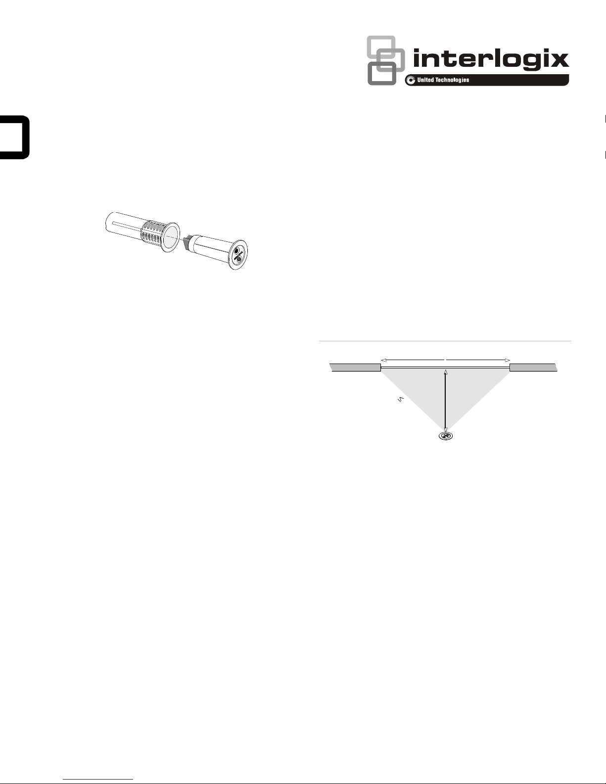
Optimum
detection
zone
D is distance from glass.
The optimum performance zone
is distance D in either direction
on the glass.
ShatterPro
D
2
5
f
t.
ShatterPro II Advanced Acoustic Sensor with
Pattern Recognition Technology Installation
Instructions
The mounting location can affect sensor detection ability. To
ensure optimum performance, the coverage zone width should
be no greater than two times the distance from the sensor to
the closest point of glass. For instance, if a sensor is mounted
SEE PAGE 4 FOR IMPORTANT WARNINGS, DISCLAIMERS,
AND PRODUCT/SAFETY INFORMATION.
10 ft. (3 m) from the glass, its optimum performance zone will
be 10 ft. (3 m) in either direction of the midpoint. You can
mount the sensors from 3.3 to 25 ft. (1 to 7.6 m) from the
farthest point of the glass. Figure 1 below shows the coverage
zone with D being the distance from the glass.
Introduction
This is the 5820A-W and 5825A-W ShatterPro II Advanced
Acoustic Sensor Installation Instructions. The ShatterPro II
sensor is designed to detect breaking glass from framed
windows in the perimeter of a building.
Install the sensors on a perimeter loop armed whenever the
door and window contacts are armed. To prevent false alarms,
avoid applications where glassbreak sensors are configured to
be active in all arming levels.
The sensor false alarm immunity technology functions best in
rooms with only moderate noise. Some sounds can duplicate
the points on the glassbreak pattern the sensors detect.
The sensors may not consistently detect cracks in glass or
bullets that break through the glass. Always complement
glassbreak sensors with interior protection.
Connect the sensors to a UL Listed control panel, or a power
supply that provides at least four hours of standby power.
Mounting location
You can mount the sensors on the ceiling or on a wall.
Wall mount
The best wall-mount location is on the wall opposite to the
glass to be protected, assuming this glass is within the sensor
range and line of sight. You can also use the adjoining wall.
Figure 1: Coverage zone
Use the following guidelines to determine the best mounting
location:
• Mount the sensors at least 3.3 ft. (1 m) from the windows
being protected and at least 4 ft. (1.2 m) from noise
sources such as TV’s, speakers, sinks and doors.
• Mount the sensors in the direct line of sight of the glass to
be protected.
• Avoid rooms smaller than 10 by 10 ft. (3 m by 3 m).
• Avoid locations where lined, insulating, or sound
deadening drapes or closed wooden shutters are used.
• Mount the sensors in a suitable environment: temperature
between 0 and 120°F (−18 and 50°C); and humidity
between 10 and 90% noncondensing. Do not install the
sensors in humid rooms. Excess moisture on the circuit
boards can eventually cause a short and a false alarm.
Ceiling mount
Mount the sensors in a location that is in direct line of sight of
the glass to be protected. However, since sound travels out
from a broken window, a position 8 ft. (2.4 m) into the room
provides better detection.
© 2017 UTC Fire & Security Americas Corporation, Inc. 1 / 6 P/N 466-2934 • REV A • ISS 26MAY17
• Mount the sensors on a stable surface up to 25 ft. (7.6 m)
from the farthest point on the glass surface.
Page 2
25 ft. (7.5 m)
2
5
f
t
.
(
7
.
5
m
)
Hold tester so that the speaker is
within 1 inch of sensor microphone.
In test mode the sensor LED will light
solid for about 4 seconds,
then blink for about a minute.
1 inch
• Avoid locations that expose the sensors to possible false
alarm sources such as:
- Glass airlocks and vestibule areas
- Kitchens
- Corner mountings
- Residential car garages
- Small utility rooms
- Stairwells
- Bathrooms
- Small acoustically live rooms
Coverage range
The sensors are omnidirectional, providing 360° coverage.
Coverage is measured from a sensor to the point on the glass
farthest from the sensor. The sensors can be mounted as
close as 3.3 ft. (1 m) from the glass. The maximum range
depends on the type of glass being protected:
Armor-coated glass
Mount the sensors no more than 12 ft. (3.65 m) from the glass.
Plate, tempered, laminated, and wired glass
When the sensors are mounted on the ceiling or the opposite
or adjoining wall, (Figure 2 below) maximum range is 25 ft.
(7.5 m).
Figure 2: Maximum coverage range
test mode, the LED will blink continuously. To extend test
time, activate the tester at least once a minute.
When the system is armed and the sensor trips to an alarm
condition, the LED will light solid for four seconds and then
revert back to a one minute test mode. At the end of one
minute, the LED will extinguish if it is in set up LED mode, or
the LED will light if it is in latching LED mode.
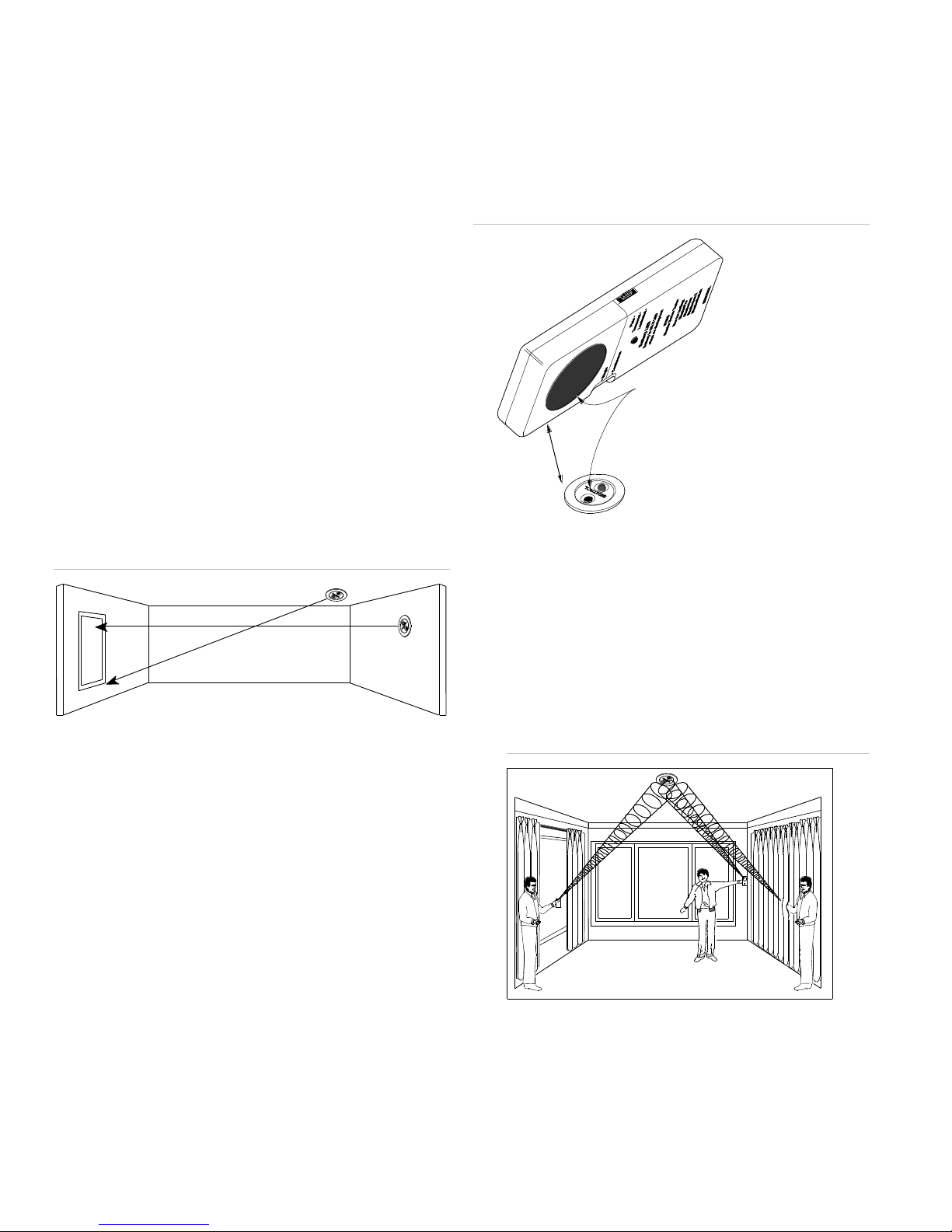
Figure 3: Activating test mode
Sensor test
Before you can test the sensors, they must be in test mode
(blinking). To test the sensors, do the following:
1. Choose the laminated setting on the tester.
Testing
Test the sensor upon installation and if the window glass-type
is changed.
The sensors are designed to detect the breaking of framed
glass mounted in an outside wall. Testing the sensors with
unframed glass, broken bottles, etc., may not trip the sensors.
The sensors typically do not trip to glass breaking in the middle
of the room. To verify sensor range and operation, you need to
use the UTC Fire & Security 5709C hand-held tester.
Test mode
To put the sensors in test mode, do the following:
1. Connect a 9-volt battery to the sensor for pretesting.
2. Temporarily mount sensor in the desired location.
3. Use the 5709C hand-held tester to put the sensor into test
mode. Set the tester to tempered glass and hold the tester
on top of the sensor (Figure 3 below). Activate the tester,
this will trip the sensor into test mode for one minute. In
2. Hold the tester near the surface of the glass to be
protected and aim the speaker at the sensor. Be sure the
tester is at the point on the glass farthest from the sensor.
If closed drapes or curtains are present, hold the tester
behind them (Figure 4 below).
Figure 4: Testing behind curtains
3. Press the test button on the tester. The LED on the sensor
should stay on for four seconds to indicate the glass is
within detection range of the sensor. If the LED does not
stay on for four seconds, move the sensor and retest.
For latching LED, provide a power reset by removing power
and resetting the LED.
2 / 6 P/N 466-2934 • REV A • ISS 26MAY17
Page 3

Voltage
9 to 16 VDC
Current:
Typical
Maximum
15 mA
25 mA
Relay output:
On resistance
Off resistance
Normally closed, open 4 seconds upon alarm
10 Ω −5 +10
> 1 MΩ
Maximum loop rating
16 VDC, 50 mA (relay)
Detection range
3.3 to 25 ft. (1 to 7.5 m) , 360°
Minimum glass size
12 by 24 in. (0.3 by 0.6 m)
Recommended glass
thickness:
Plate
Tempered
Wired
Laminated
3/32 to 1/4 in. (2.4 to 6.4 mm)
1/8 to 1/4 in. (3.2 to 6.4 mm)
1/4 in. (6.4 mm)
1/8 to 1/4 in. (3.2 to 6.4 mm)
Operating temperature
0 to 120°F (−18 to 50°C)
Relative humidity
10 to 90% noncondensing
Microphone
Omnidirectional electret
Color
White
Wiring terminals
14-22 AWG
Manufacturer
UTC Fire & Security Americas Corporation, Inc.
3211 Progress Drive, Lincolnton, NC, 28092, USA
AUTHORIZED EU REPRESENTATIVE:
UTC Fire & Security B.V.
Kelvinstraat 7, 6003 DH Weert, Netherlands
FCC/IC
This equipment has been tested and found to comply
with the limits for a Class B digital device, pursuant to
Part 15 of the FCC Rules. These limits are designed
to provide reasonable protection against harmful
interference in a residential installation.
This equipment generates, uses, and can radiate radio
frequency energy and, if not installed and used in
accordance with the instructions, may cause harmful
interference to radio communications. However, there
is no guarantee that interference will not occur in a
particular installation.
If this equipment does cause harmful interference to
radio or television reception, which can be determined
by turning the equipment off and on, the user is
encouraged to try to correct the interference by one or
more of the following measures:
- Reorient or relocate the receiving antenna.
- Increase the separation between the equipment
and receiver.
- Connect the equipment into an outlet on a circuit
5825A Single Gang Box
ShatterPro™ II
2.53 in. diameter (6.43 cm)
1 in. diameter hole (2.54 cm)
5829A Single Gang Box Plate
4.5 in.
(11.43 cm)
2.75 in.
(6.99 cm)
(Back box
not included)
Cut for
latching LED
Installation
All wiring must conform to the National Electric Code (NEC)
and/or local codes having jurisdiction.
Do not install sensors in rooms with ultrasonic sensors.
To mount the sensor on a wall or ceiling, do the following:
1. Drill a 1 in. (2.5 cm) hole. For hard woods, drill a 1 1/16 in.
(2.7 cm) hole. For a cleaner hole, use a spade bit rather
than a twist bit.
2. Run wires through the hole and the sleeve to the sensor.
3. Connect wires to the wire terminals as shown in “Wiring”
below.
4. Insert the sleeve into the mounting hole and insert the
sensor into the sleeve, matching the ribs on the sensor
with the grooves on the sleeve.
To mount the Single-gang Box ShatterPro II model (5825A-W)
in a single-gang box, see Figure 5 below and do the following:
1. Mount the adaptor bracket to the single-gang box (not
included) and mount the adaptor plate to the bracket.
2. Run wires through the wire entry hole and sleeve to the
sensor.
3. Connect wires to the wire terminals as shown in “Wiring”
below.
Maintenance
When installed and used properly, minimal maintenance is
required. You should test the sensors annually to ensure
proper operation.
Clean the covers with a damp (water) cloth as needed to keep
it free of dust and dirt. Always test the sensors after cleaning
them.
Specifications
4. Insert the sleeve into the adaptor plate and insert the
sensor into the sleeve, matching the ribs on the sensor
with the grooves in the sleeve.
Figure 5: Recessed mounting in a single gang box
Wiring
Strip back the outer jacket on your wiring cable. This allows
wires to flex in the case. Make sure the cable is slack in the
wall to avoid stressing the wires at their connections.
Figure 6 below shows the wiring terminals for ShatterPro II.
Figure 6: ShatterPro II wiring terminals
P/N 466-2934 • REV A • ISS 26MAY17 3 / 6
Regulatory information
Page 4

different from that to which the receiver is
connected.
- Consult the dealer or an experienced radio/TV
technician for help.
Changes or modifications not expressly approved by
UTC Fire and Security could void the user’s authority
to operate the equipment.
This device complies with Industry Canada licenseexempt RSS standard(s). Operation is subject to the
following two conditions: (1) this device may not cause
interference, and (2) this device must accept any
interference, including interference that may cause
undesired operation of the device.
Cet appareil est conforme avec Industrie Canada
exempts de licence standard RSS (s). Son
fonctionnement est soumis aux deux conditions
suivantes: (1) cet appareil ne doit pas provoquer
d'interférences et (2) cet appareil doit accepter toute
interférence, y compris celles pouvant causer un
mauvais fonctionnement de l'appareil.
Copyright
Copyright © 2017 United Technologies Corporation.
All rights reserved.
Trademarks
Interlogix is a registered trademark of United
Technologies Corporation. Interlogix is part of UTC
Climate, Controls & Security, a unit of United
Technologies Corporation.
Product
warnings
THESE PRODUCTS ARE INTENDED FOR SALE TO
AND INSTALLATION BY AN EXPERIENCED
SECURITY PROFESSIONAL. UTC FIRE &
SECURITY AMERICAS CORPORATION, INC.
("INTERLOGIX") CANNOT PROVIDE ANY
ASSURANCE THAT ANY PERSON OR ENTITY
BUYING ITS PRODUCTS, INCLUDING ANY
“AUTHORIZED DEALER”, IS PROPERLY TRAINED
OR EXPERIENCED TO CORRECTLY INSTALL
SECURITY RELATED PRODUCTS.
A PROPERLY INSTALLED AND MAINTAINED
ALARM/SECURITY SYSTEM MAY ONLY REDUCE
THE RISK OF EVENTS SUCH AS BREAK-INS,
BURGLARY, ROBBERY OR FIRE; IT IS NOT
INSURANCE OR A GUARANTEE THAT SUCH
EVENTS WILL NOT OCCUR, THAT ADEQUATE
WARNING OR PROTECTION WILL BE PROVIDED,
OR THAT THERE WILL BE NO DEATH, PERSONAL
INJURY, AND/OR PROPERTY DAMAGE AS A
RESULT.
WHILE INTERLOGIX MAKES REASONABLE
EFFORTS TO REDUCE THE PROBABILITY THAT A
THIRD PARTY MAY HACK, COMPROMISE OR
CIRCUMVENT ITS SECURITY PRODUCTS,
RELATED SOFTWARE OR CLOUD SERVERS, ANY
SECURITY PRODUCT, SOFTWARE OR CLOUD
SERVER MANUFACTURED, SOLD AND/OR
LICENSED BY INTERLOGIX, MAY STILL BE
HACKED, COMPROMISED AND/OR
CIRCUMVENTED.
CERTAIN PRODUCTS OR SOFTWARE
MANUFACTURED, SOLD OR LICENSED BY
INTERLOGIX CONNECT TO THE INTERNET TO
SEND AND/OR RECEIVE DATA (“INTERNET OF
THINGS” OR “IOT” PRODUCTS). ANY CONTINUED
USE OF AN IOT PRODUCT AFTER INTERLOGIX
HAS CEASED SUPPORTING THAT IOT PRODUCT
(E.G., THROUGH NOTICE THAT INTERLOGIX NO
LONGER PROVIDES FIRMWARE UPDATES OR
BUG FIXES) MAY RESULT IN REDUCED
PERFORMANCE, MALFUNCTION, AND/OR
INCREASED VULNERABILITY TO HACKING,
COMPROMISE AND/OR CIRCUMVENTION.
INTERLOGIX DOES NOT ENCRYPT
COMMUNICATIONS BETWEEN ITS ALARM OR
SECURITY PANELS AND THEIR OUTPUTS/INPUTS
INCLUDING, BUT NOT LIMITED TO, SENSORS OR
DETECTORS UNLESS REQUIRED BY APPLICABLE
LAW. AS A RESULT THESE COMMUNICATIONS
MAY BE INTERCEPTED AND COULD BE USED TO
CIRCUMVENT YOUR ALARM/SECURITY SYSTEM.
THE ABILITY OF INTERLOGIX PRODUCTS AND
SOFTWARE TO WORK PROPERLY DEPENDS ON
A NUMBER OF PRODUCTS AND SERVICES MADE
AVAILABLE BY THIRD PARTIES OVER WHICH
INTERLOGIX HAS NO CONTROL INCLUDING, BUT
NOT LIMITED TO, INTERNET, CELLULAR AND
LANDLINE CONNECTIVITY; MOBILE DEVICE AND
OPERATING SYSTEM COMPATIBILITY; AND
PROPER INSTALLATION AND MAINTENANCE.
INTERLOGIX SHALL NOT BE LIABLE FOR ANY
DAMAGES CAUSED BY ACTIONS OR OMISSIONS
OF THIRD PARTIES.
BATTERY OPERATED SENSORS, DETECTORS,
KEYFOBS, PANIC DEVICES AND OTHER PANEL
ACCESSORIES HAVE A LIMITED BATTERY LIFE.
WHILE THESE PRODUCTS MAY BE DESIGNED TO
PROVIDE SOME WARNING OF IMMINENT
BATTERY DEPLETION, THE ABILITY TO DELIVER
SUCH WARNINGS IS LIMITED AND SUCH
WARNINGS MAY NOT BE PROVIDED IN ALL
CIRCUMSTANCES. PERIODIC TESTING OF THE
SYSTEM IN ACCORDANCE WITH PRODUCT
DOCUMENTATION IS THE ONLY WAY TO
DETERMINE IF ALL SENSORS, DETECTORS,
KEYFOBS, PANIC DEVICES AND OTHER PANEL
ACCESSORIES ARE FUNCTIONING PROPERLY.
CERTAIN SENSORS, PANIC DEVICES AND OTHER
PANEL ACCESSORIES MAY BE PROGRAMMED
INTO AN ALARM PANEL AS “SUPERVISORY” SO
THAT THE ALARM PANEL WILL INDICATE IF IT
DOES NOT RECEIVE A REGULAR SIGNAL FROM
THE DEVICE WITHIN A CERTAIN PERIOD OF TIME.
CERTAIN DEVICES CANNOT BE PROGRAMMED
AS SUPERVISORY. DEVICES CAPABLE OF BEING
PROGRAMMED AS SUPERVISORY MAY NOT BE
PROPERLY PROGRAMMED AT INSTALLATION,
RESULTING IN A FAILURE TO REPORT TROUBLE
WHICH COULD RESULT IN DEATH, SERIOUS
INJURY AND/OR PROPERTY DAMAGE.
SIRENS/SOUNDERS, INCLUDING INTERNAL
SIRENS/SOUNDERS IN PANELS, ARE DESIGNED
TO EMIT VERY LOUD SOUNDS. THESE SOUNDS
CAN CAUSE HEARING DAMAGE TO PERSONS
EITHER IN CLOSE PROXIMITY TO THE
SIREN/SOUNDER WHEN ACTIVATED OR
EXPOSED TO SUCH SOUNDS OVER LONGER
PERIODS OF TIME.
Warranty
disclaimers
and other
disclaimers
INTERLOGIX HEREBY DISCLAIMS ALL
WARRANTIES AND REPRESENTATIONS,
WHETHER EXPRESS, IMPLIED, STATUTORY OR
OTHERWISE INCLUDING (BUT NOT LIMITED TO)
ANY WARRANTIES OF MERCHANTABILITY OR
FITNESS FOR A PARTICULAR PURPOSE WITH
RESPECT TO ITS SECURITY PRODUCTS AND
RELATED SOFTWARE. INTERLOGIX FURTHER
DISCLAIMS ANY OTHER IMPLIED WARRANTY
UNDER THE UNIFORM COMPUTER INFORMATION
4 / 6 P/N 466-2934 • REV A • ISS 26MAY17
Page 5

TRANSACTIONS ACT OR SIMILAR LAW AS
ENACTED BY ANY COUNTRY.
(USA ONLY) SOME STATES DO NOT ALLOW THE
EXCLUSION OF IMPLIED WARRANTIES, SO THE
ABOVE EXCLUSION MAY NOT APPLY TO YOU.
THIS WARRANTY GIVES YOU SPECIFIC LEGAL
RIGHTS AND YOU MAY ALSO HAVE OTHER
LEGAL RIGHTS THAT VARY FROM STATE TO
STATE.
INTERLOGIX MAKES NO REPRESENTATION,
WARRANTY, COVENANT OR PROMISE THAT ITS
SECURITY PRODUCTS AND/OR RELATED
SOFTWARE (I) WILL NOT BE HACKED,
COMPROMISED AND/OR CIRCUMVENTED; (II)
WILL PREVENT, OR PROVIDE ADEQUATE
WARNING OR PROTECTION FROM, BREAK-INS,
BURGLARY, ROBBERY, FIRE; OR (III) WILL WORK
PROPERLY IN ALL ENVIRONMENTS AND
APPLICATIONS.
INTERLOGIX WILL NOT BE LIABLE FOR
UNAUTHORIZED ACCESS (I.E., HACKING) INTO
THE CLOUD SERVERS OR YOUR TRANSMISSION
FACILITIES, PREMISES OR EQUIPMENT, OR FOR
UNAUTHORIZED ACCESS TO DATA FILES,
PROGRAMS, PROCEDURES OR INFORMATION
THEREON, UNLESS AND ONLY TO THE EXTENT
THAT THIS DISCLAIMER IS PROHIBITED BY
APPLICABLE LAW.
SYSTEMS SHOULD BE CHECKED BY A QUALIFIED
TECHNICIAN AT LEAST EVERY 3 YEARS UNLESS
OTHERWISE INSTRUCTED IN THE PRODUCT
DOCUMENTATION AND, IF APPLICABLE, THE
BACKUP BATTERY REPLACED AS REQUIRED.
THE INFORMATION IN THIS DOCUMENT IS
SUBJECT TO CHANGE WITHOUT NOTICE.
UPDATED INFORMATION CAN BE FOUND AT
WWW.UTCFSSECURITYPRODUCTS.EU/PRODUCT
WARNING/. INTERLOGIX ASSUMES NO
RESPONSIBILITY FOR INACCURACIES OR
OMISSIONS AND SPECIFICALLY DISCLAIMS ANY
LIABILITIES, LOSSES, OR RISKS, PERSONAL OR
OTHERWISE, INCURRED AS A CONSEQUENCE,
DIRECTLY OR INDIRECTLY, OF THE USE OR
APPLICATION OF ANY OF THE CONTENTS OF
THIS DOCUMENT.
THIS PUBLICATION MAY CONTAIN EXAMPLES OF
SCREEN CAPTURES AND REPORTS USED IN
DAILY OPERATIONS. EXAMPLES MAY INCLUDE
FICTITIOUS NAMES OF INDIVIDUALS AND
COMPANIES. ANY SIMILARITY TO NAMES AND
ADDRESSES OF ACTUAL BUSINESSES OR
PERSONS IS ENTIRELY COINCIDENTAL.
REFER TO THE DATA SHEET AND USER
DOCUMENTATION FOR INFORMATION ON USE.
FOR THE LATEST PRODUCT INFORMATION,
CONTACT YOUR SUPPLIER OR VISIT
WWW.INTERLOGIX.COM.
2012/19/EU (WEEE directive): Products marked with
this symbol cannot be disposed of as unsorted
municipal waste in the European Union. For proper
recycling, return this product to your local supplier
upon the purchase of equivalent new equipment, or
dispose of it at designated collection points. For more
information see:
www.utcfssecurityproducts.eu/recycle/
Product
Description
5820A-W
Recessed ShatterPro II, latch or nonlatch LED
5825A-W
Single-gang Box ShatterPro II
Accessories
5709C-W
Glassbreak hand-held tester
P/N 466-2934 • REV A • ISS 26MAY17 5 / 6
Product ordering
Contact information
www.interlogix.com
For customer support, see www.interlogix.com/customer-
support
Page 6

6 / 6 P/N 466-2934 • REV A • ISS 26MAY17
 Loading...